WO2013080487A1 - 円筒状ガスケット及びその製造方法並びに該円筒状ガスケットを使用した差し込み型排気管継手 - Google Patents
円筒状ガスケット及びその製造方法並びに該円筒状ガスケットを使用した差し込み型排気管継手 Download PDFInfo
- Publication number
- WO2013080487A1 WO2013080487A1 PCT/JP2012/007444 JP2012007444W WO2013080487A1 WO 2013080487 A1 WO2013080487 A1 WO 2013080487A1 JP 2012007444 W JP2012007444 W JP 2012007444W WO 2013080487 A1 WO2013080487 A1 WO 2013080487A1
- Authority
- WO
- WIPO (PCT)
- Prior art keywords
- cylindrical
- acid
- graphite powder
- heat
- peripheral surface
- Prior art date
- Legal status (The legal status is an assumption and is not a legal conclusion. Google has not performed a legal analysis and makes no representation as to the accuracy of the status listed.)
- Ceased
Links
Images


Classifications
-
- F—MECHANICAL ENGINEERING; LIGHTING; HEATING; WEAPONS; BLASTING
- F16—ENGINEERING ELEMENTS AND UNITS; GENERAL MEASURES FOR PRODUCING AND MAINTAINING EFFECTIVE FUNCTIONING OF MACHINES OR INSTALLATIONS; THERMAL INSULATION IN GENERAL
- F16J—PISTONS; CYLINDERS; SEALINGS
- F16J15/00—Sealings
- F16J15/02—Sealings between relatively-stationary surfaces
- F16J15/06—Sealings between relatively-stationary surfaces with solid packing compressed between sealing surfaces
- F16J15/10—Sealings between relatively-stationary surfaces with solid packing compressed between sealing surfaces with non-metallic packing
- F16J15/104—Sealings between relatively-stationary surfaces with solid packing compressed between sealing surfaces with non-metallic packing characterised by structure
-
- F—MECHANICAL ENGINEERING; LIGHTING; HEATING; WEAPONS; BLASTING
- F16—ENGINEERING ELEMENTS AND UNITS; GENERAL MEASURES FOR PRODUCING AND MAINTAINING EFFECTIVE FUNCTIONING OF MACHINES OR INSTALLATIONS; THERMAL INSULATION IN GENERAL
- F16J—PISTONS; CYLINDERS; SEALINGS
- F16J15/00—Sealings
- F16J15/02—Sealings between relatively-stationary surfaces
- F16J15/06—Sealings between relatively-stationary surfaces with solid packing compressed between sealing surfaces
- F16J15/10—Sealings between relatively-stationary surfaces with solid packing compressed between sealing surfaces with non-metallic packing
- F16J15/12—Sealings between relatively-stationary surfaces with solid packing compressed between sealing surfaces with non-metallic packing with metal reinforcement or covering
- F16J15/121—Sealings between relatively-stationary surfaces with solid packing compressed between sealing surfaces with non-metallic packing with metal reinforcement or covering with metal reinforcement
- F16J15/126—Sealings between relatively-stationary surfaces with solid packing compressed between sealing surfaces with non-metallic packing with metal reinforcement or covering with metal reinforcement consisting of additions, e.g. metallic fibres, metallic powders, randomly dispersed in the packing
-
- B—PERFORMING OPERATIONS; TRANSPORTING
- B29—WORKING OF PLASTICS; WORKING OF SUBSTANCES IN A PLASTIC STATE IN GENERAL
- B29C—SHAPING OR JOINING OF PLASTICS; SHAPING OF MATERIAL IN A PLASTIC STATE, NOT OTHERWISE PROVIDED FOR; AFTER-TREATMENT OF THE SHAPED PRODUCTS, e.g. REPAIRING
- B29C43/00—Compression moulding, i.e. applying external pressure to flow the moulding material; Apparatus therefor
- B29C43/003—Compression moulding, i.e. applying external pressure to flow the moulding material; Apparatus therefor characterised by the choice of material
-
- B—PERFORMING OPERATIONS; TRANSPORTING
- B29—WORKING OF PLASTICS; WORKING OF SUBSTANCES IN A PLASTIC STATE IN GENERAL
- B29C—SHAPING OR JOINING OF PLASTICS; SHAPING OF MATERIAL IN A PLASTIC STATE, NOT OTHERWISE PROVIDED FOR; AFTER-TREATMENT OF THE SHAPED PRODUCTS, e.g. REPAIRING
- B29C43/00—Compression moulding, i.e. applying external pressure to flow the moulding material; Apparatus therefor
- B29C43/02—Compression moulding, i.e. applying external pressure to flow the moulding material; Apparatus therefor of articles of definite length, i.e. discrete articles
- B29C43/18—Compression moulding, i.e. applying external pressure to flow the moulding material; Apparatus therefor of articles of definite length, i.e. discrete articles incorporating preformed parts or layers, e.g. compression moulding around inserts or for coating articles
-
- F—MECHANICAL ENGINEERING; LIGHTING; HEATING; WEAPONS; BLASTING
- F01—MACHINES OR ENGINES IN GENERAL; ENGINE PLANTS IN GENERAL; STEAM ENGINES
- F01N—GAS-FLOW SILENCERS OR EXHAUST APPARATUS FOR MACHINES OR ENGINES IN GENERAL; GAS-FLOW SILENCERS OR EXHAUST APPARATUS FOR INTERNAL-COMBUSTION ENGINES
- F01N13/00—Exhaust or silencing apparatus characterised by constructional features
- F01N13/08—Other arrangements or adaptations of exhaust conduits
-
- F—MECHANICAL ENGINEERING; LIGHTING; HEATING; WEAPONS; BLASTING
- F01—MACHINES OR ENGINES IN GENERAL; ENGINE PLANTS IN GENERAL; STEAM ENGINES
- F01N—GAS-FLOW SILENCERS OR EXHAUST APPARATUS FOR MACHINES OR ENGINES IN GENERAL; GAS-FLOW SILENCERS OR EXHAUST APPARATUS FOR INTERNAL-COMBUSTION ENGINES
- F01N13/00—Exhaust or silencing apparatus characterised by constructional features
- F01N13/18—Construction facilitating manufacture, assembly, or disassembly
- F01N13/1805—Fixing exhaust manifolds, exhaust pipes or pipe sections to each other, to engine or to vehicle body
- F01N13/1827—Sealings specially adapted for exhaust systems
-
- F—MECHANICAL ENGINEERING; LIGHTING; HEATING; WEAPONS; BLASTING
- F01—MACHINES OR ENGINES IN GENERAL; ENGINE PLANTS IN GENERAL; STEAM ENGINES
- F01N—GAS-FLOW SILENCERS OR EXHAUST APPARATUS FOR MACHINES OR ENGINES IN GENERAL; GAS-FLOW SILENCERS OR EXHAUST APPARATUS FOR INTERNAL-COMBUSTION ENGINES
- F01N13/00—Exhaust or silencing apparatus characterised by constructional features
- F01N13/18—Construction facilitating manufacture, assembly, or disassembly
- F01N13/1838—Construction facilitating manufacture, assembly, or disassembly characterised by the type of connection between parts of exhaust or silencing apparatus, e.g. between housing and tubes, between tubes and baffles
- F01N13/1844—Mechanical joints
- F01N13/185—Mechanical joints the connection being realised by deforming housing, tube, baffle, plate, or parts thereof
-
- F—MECHANICAL ENGINEERING; LIGHTING; HEATING; WEAPONS; BLASTING
- F16—ENGINEERING ELEMENTS AND UNITS; GENERAL MEASURES FOR PRODUCING AND MAINTAINING EFFECTIVE FUNCTIONING OF MACHINES OR INSTALLATIONS; THERMAL INSULATION IN GENERAL
- F16J—PISTONS; CYLINDERS; SEALINGS
- F16J15/00—Sealings
- F16J15/02—Sealings between relatively-stationary surfaces
- F16J15/06—Sealings between relatively-stationary surfaces with solid packing compressed between sealing surfaces
- F16J15/10—Sealings between relatively-stationary surfaces with solid packing compressed between sealing surfaces with non-metallic packing
- F16J15/12—Sealings between relatively-stationary surfaces with solid packing compressed between sealing surfaces with non-metallic packing with metal reinforcement or covering
- F16J15/121—Sealings between relatively-stationary surfaces with solid packing compressed between sealing surfaces with non-metallic packing with metal reinforcement or covering with metal reinforcement
-
- F—MECHANICAL ENGINEERING; LIGHTING; HEATING; WEAPONS; BLASTING
- F16—ENGINEERING ELEMENTS AND UNITS; GENERAL MEASURES FOR PRODUCING AND MAINTAINING EFFECTIVE FUNCTIONING OF MACHINES OR INSTALLATIONS; THERMAL INSULATION IN GENERAL
- F16L—PIPES; JOINTS OR FITTINGS FOR PIPES; SUPPORTS FOR PIPES, CABLES OR PROTECTIVE TUBING; MEANS FOR THERMAL INSULATION IN GENERAL
- F16L21/00—Joints with sleeve or socket
- F16L21/06—Joints with sleeve or socket with a divided sleeve or ring clamping around the pipe ends
- F16L21/065—Joints with sleeve or socket with a divided sleeve or ring clamping around the pipe ends tightened by tangentially-arranged threaded pins
-
- B—PERFORMING OPERATIONS; TRANSPORTING
- B29—WORKING OF PLASTICS; WORKING OF SUBSTANCES IN A PLASTIC STATE IN GENERAL
- B29L—INDEXING SCHEME ASSOCIATED WITH SUBCLASS B29C, RELATING TO PARTICULAR ARTICLES
- B29L2031/00—Other particular articles
- B29L2031/26—Sealing devices, e.g. packaging for pistons or pipe joints
- B29L2031/265—Packings, Gaskets
-
- F—MECHANICAL ENGINEERING; LIGHTING; HEATING; WEAPONS; BLASTING
- F01—MACHINES OR ENGINES IN GENERAL; ENGINE PLANTS IN GENERAL; STEAM ENGINES
- F01N—GAS-FLOW SILENCERS OR EXHAUST APPARATUS FOR MACHINES OR ENGINES IN GENERAL; GAS-FLOW SILENCERS OR EXHAUST APPARATUS FOR INTERNAL-COMBUSTION ENGINES
- F01N2470/00—Structure or shape of exhaust gas passages, pipes or tubes
- F01N2470/24—Concentric tubes or tubes being concentric to housing, e.g. telescopically assembled
Definitions
- the present invention relates to a cylindrical gasket suitable for use in a plug-in type exhaust pipe joint used in vehicles such as ATV (All Terrain Vehicle), snowmobiles, two-wheeled vehicles, etc., a manufacturing method thereof, and the cylindrical gasket
- ATV All Terrain Vehicle
- snowmobiles snowmobiles
- two-wheeled vehicles etc.
- a manufacturing method thereof and the cylindrical gasket
- the present invention relates to a plug-in type exhaust pipe joint.
- the plug-in type exhaust pipe joint has an inner pipe and an outer pipe having an inner diameter substantially the same as the outer diameter of the inner pipe, and the outer pipe has an enlarged diameter portion at the end of the pipe.
- the inner tube has a tube end portion that passes through the diameter-enlarged portion of the outer tube and is fitted to the tube end portion of the outer tube at one end, and the tube end portion of the inner tube and the diameter-enlarged portion of the outer tube A gasket is fitted in an annular gap between the inner and outer pipes, and a gap between the inner and outer pipes is sealed by a fastening band disposed on the outer peripheral surface of the outer pipe (Patent Document 1). Patent Document 2 and Patent Document 3).
- an expanded graphite sheet is cut into a strip having a certain width and length, and on the strip, the length of the expanded graphite sheet is approximately the same.
- a metal mesh cut into equal lengths is placed on top of each other and wound around a cylindrical core bar with the wire mesh inside to produce a cylindrical body.
- the cylindrical body is placed in a mold and its axial direction.
- a gasket in which a metal mesh or expanded graphite is exposed on the inner peripheral surface, and both end surfaces and the outer peripheral surface thereof are covered with expanded graphite (see Patent Document 1 and Patent Document 3).
- a gasket main body surrounded by a metal mesh material is provided on the entire surface of the expanded graphite sheet.
- the gasket main body is annularly bent and compressed by a press to integrally fix the expanded graphite and the mesh material.
- An annular gasket has also been proposed (see Patent Document 4).
- the gasket made of expanded graphite and wire mesh disposed between the inner pipe of the exhaust pipe joint and the enlarged diameter part of the outer pipe expands in volume by the heat of the exhaust gas flowing in the inner pipe and is flexible and flexible. Therefore, it can adapt well to the gap between the inner tube and the outer tube, and can improve the sealing performance between the inner tube and the outer tube (see Patent Document 1). ).
- JP-A 61-244815 Japanese Utility Model Publication No. 6-36273 JP-A-6-146875 Japanese Utility Model Publication No. 5-47620
- the exhaust pipe has become larger as a countermeasure against noise, and a catalyst device has been mounted on the exhaust pipe as a countermeasure against exhaust gas, and an excessive load has been applied to the plug-in type exhaust pipe joint. ing.
- vibration load, bending torque, and twisting between the inner and outer pipes are repeatedly generated at the joint part.
- the gasket With respect to the vibration load, bending torque and twist that are repeatedly generated as described above, the gasket has the flexibility required for exerting hermeticity and the rigidity for receiving the tightening force without causing settling when tightening with the tightening band. Is required.
- the above-described conventional gaskets are specialized in either flexibility or rigidity, and it is difficult to achieve both performances.
- gaskets specialized in rigidity As a result, gaskets specialized in rigidity.
- the sealing performance of the gap between the inner and outer pipes is reduced due to loosening of the tightening band caused by the gasket settling or the like. May cause problems.
- the present invention has been made in view of the above-mentioned points, and an object of the present invention is to provide a cylindrical gasket suitable for use in a plug-in type exhaust pipe joint, which has both sealing performance and rigidity, a manufacturing method thereof, and the It is an object of the present invention to provide a plug-in type exhaust pipe joint using a cylindrical gasket.
- the cylindrical gasket used in the plug-in type exhaust pipe joint of the present invention includes a reinforcing material made of a compressed wire mesh, and graphite, acid-treated graphite and an inorganic binder that are filled and compressed in the mesh of the wire mesh of the reinforcing material And a reinforcing material and pores distributed in the heat-resistant material, the reinforcing material and the heat-resistant material are intertwined with each other and have structural integrity,
- the material is densely contained in the radial direction from the cylindrical inner peripheral surface to the cylindrical outer peripheral surface.
- the reinforcing material has a volume of 32 to 60% of the entire volume of the cylindrical gasket, and the heat resistant material. Is characterized by occupying a volume of 5 to 58% and pores occupying a volume of 10 to 35%.
- the content ratios of the reinforcing material and the heat-resistant material are 32 to 60% and 5 to 58%, respectively, by volume, and the reinforcing material is formed from the cylindrical inner peripheral surface to the cylindrical outer periphery.
- the reinforcing material made mainly of the metal mesh bears the load caused by the tightening force and vibration by the fastening band, so that it is difficult for the settling to occur, and the mesh of the reinforcement mesh It is filled with heat-resistant material and has a pore content of 10-35% by volume. Therefore, it has excellent sealing performance. Therefore, it has both sealing performance and rigidity. It can be used to provide a suitable cylindrical gasket.
- the acid-treated graphite contained in the heat-resistant material has undergone volume expansion due to the heat of the exhaust gas flowing in the exhaust pipe of the exhaust pipe joint in which the cylindrical gasket is incorporated, It expand
- the cylindrical gasket of the present invention the heat of the exhaust gas flowing in the exhaust pipe of the exhaust pipe joint in which the cylindrical gasket is incorporated, the condensation by heat dehydration and high temperature on the inorganic binder contained in the heat-resistant material. Curing bondability is manifested by the transition of crystals by heating, etc., thereby further increasing the rigidity of the cylindrical gasket.
- the graphite contained in the heat-resistant material is preferably artificial graphite made of natural graphite, quiche graphite, or pyrolytic graphite made of scale-like graphite, earthy graphite, scale-like graphite, and massive graphite. And at least one selected from expanded graphite.
- the acid-treated graphite contained in the heat-resistant material is subjected to the above-mentioned natural graphite or artificial graphite powder with inorganic acid such as concentrated sulfuric acid, nitric acid, selenic acid, concentrated nitric acid, perchlorine.
- inorganic acid such as concentrated sulfuric acid, nitric acid, selenic acid, concentrated nitric acid, perchlorine.
- strong oxidizing agents such as acid, perchlorate, permanganate, dichromate, hydrogen peroxide, etc.
- an inorganic acid is inserted between the graphite layers, and the carbon obtained by acid treatment
- a crystalline compound maintaining a layered structure is preferably used.
- the inorganic binder contained in the heat-resistant material includes aluminum dihydrogen phosphate (primary aluminum phosphate) [Al (H 2 PO 4 ) 3 ], aluminum hydrogen phosphate (second aluminum phosphate) [ Al 2 (HPO 4 ) 3 ], magnesium dihydrogen phosphate (primary magnesium phosphate) [Mg (H 2 PO 4 ) 2 ], magnesium hydrogen phosphate (secondary magnesium phosphate) (MgHPO 4 ), calcium dihydrogen phosphate (first At least one of calcium monophosphate (Ca (H 2 PO 4 ) 2 ), calcium hydrogen phosphate (CaHPO 4 ) and phosphoric acid (H 3 PO 4 ) may be selected and used.
- inorganic binders are used for joining graphite contained in a heat-resistant material, joining graphite and acid-treated graphite, joining a heat-resistant reinforcing material to a wire mesh, and an exhaust pipe in which a cylindrical gasket is incorporated.
- the effect of the heat of the exhaust gas flowing in the exhaust pipe of the joint exerts the effect of increasing the rigidity of the cylindrical gasket by exhibiting hardened bonds due to condensation by heating dehydration and crystal transition by high temperature heating.
- the mass ratio of graphite and acid-treated graphite contained in the heat-resistant material is preferably 1: 0.01 to 0.5, and the mass of graphite, acid-treated graphite and inorganic binder The ratio is preferably 1: 0.1 to 1.
- the volume expansion ratio of the acid-treated graphite is small due to the heat of the exhaust gas flowing in the exhaust pipe, and as a result, the volume expansion of the cylindrical gasket results.
- the action of sealing the gap between the inner pipe and the outer pipe of the exhaust pipe may be reduced, and if the mass ratio of acid-treated graphite exceeds 0.5 with respect to graphite 1, it will flow in the exhaust pipe.
- the volumetric expansion ratio of the acid-treated graphite is excessively increased by the action of the heat of the exhaust gas, and the rigidity of the cylindrical gasket is lowered.
- the mass of the inorganic binder is less than 0.1 with respect to the mass 1 of graphite and acid-treated graphite, the action of the inorganic binder as a binder is poor, and the heat-resistant material tends to fall off from the mesh of the reinforcing material.
- the mass of the inorganic binder exceeds 1 with respect to 1 of the mass of graphite and acid-treated graphite, in addition to the action of the inorganic binder as a binder, the inorganic binder condenses by heat dehydration and cures by crystal transition by high temperature heating, etc. Due to the manifestation of the bonding property, the rigidity of the cylindrical gasket may be excessively increased and the sealing performance may be reduced.
- a reinforcing material composed of a compressed wire mesh, a heat-resistant material containing compressed graphite, acid-treated graphite and an inorganic binder, and a reinforcing material and heat-resistant material filled in the mesh of the reinforcing wire-like wire mesh
- the reinforcing material and the heat-resistant material are intertwined with each other to have structural integrity, and the reinforcing material is radially extending from the cylindrical inner peripheral surface to the cylindrical outer peripheral surface.
- the reinforcing material has a volume of 32 to 60%
- the heat-resistant material has a volume of 5 to 58%
- the pores have a volume of 10 to 35% with respect to the total volume of the cylindrical gasket.
- the manufacturing method of the cylindrical gasket of the present invention used for plug-in type exhaust pipe joints is as follows: (1) Mixing graphite powder, acid-treated graphite powder, inorganic binder, and distilled water at a predetermined ratio And knead these together And a step of producing a mixture containing graphite powder, acid-treated graphite powder and an inorganic binder, and (2) a cylindrical wire mesh obtained by knitting a fine metal wire passed between a pair of rollers in the radial direction (3) supplying the mixture to both sides of the belt metal mesh and rolling the mixture between rollers to fill the mesh of the belt metal mesh, and then filling the mesh of the belt metal mesh; Drying the filled mixture to remove the water in the mixture, and producing a composite strip in which the mixture is filled and held in the mesh of the strip metal mesh; (4) the composite strip around the cylindrical core (5) inserting the cylindrical base material into the cylindrical hollow portion of the mold and at the same time forming the cylindrical base material in the mold. And a step of compression molding in the
- the cylindrical gasket of the present invention comprising a reinforcing material comprising a compressed wire mesh, and a heat resistant material that is filled and compressed with the mesh of the reinforcing wire mesh,
- the reinforcing material and the heat-resistant material are intertwined with each other to have structural integrity, and the reinforcing material is densely contained in the radial direction from the cylindrical inner peripheral surface to the cylindrical outer peripheral surface. It is possible to obtain a cylindrical gasket having both sealing properties and rigidity with a content ratio of pores of 32 to 60% reinforcing material, 5 to 58% heat-resistant material and 10 to 35% pores, respectively.
- the graphite powder is selected from at least one of natural graphite powder, artificial graphite powder and expanded graphite powder, and the expanded graphite powder is formed by cutting and pulverizing an expanded graphite sheet.
- the acid-treated graphite powder may be an acid-treated graphite powder before expansion treatment
- the inorganic binder may be aluminum dihydrogen phosphate, aluminum hydrogen phosphate, magnesium dihydrogen phosphate, magnesium hydrogen phosphate.
- Calcium dihydrogen phosphate, calcium hydrogen phosphate and phosphoric acid may be selected.
- the mass ratio of the graphite powder and the acid-treated graphite powder contained in the wettable mixture is 1: 0.01 to 0.5, and the mass ratio of the graphite powder and the acid-treated graphite powder to the inorganic binder is 1: 0.1 to 1.
- the plug-in type exhaust pipe joint of the present invention includes a pipe end, a diameter-enlarging cylindrical part provided with an enlarged diameter at the pipe end via an annular shoulder, and one end in the axial direction of the diameter-enlarging cylindrical part.
- An opening end provided on the outer peripheral surface of the opening end, a flange portion extending radially outward from the opening end portion, the enlarged cylindrical portion and the flange portion along the axial direction from the annular end surface of the opening end And it passes through the inside of the diameter-enlarged cylindrical part of the outer pipe provided with a plurality of slits provided equally in the circumferential direction, and is fitted to the pipe end of the outer pipe at one end.
- An inner pipe provided with a flange erected on the outer peripheral surface of the other end of the pipe end, a cylindrical outer surface of the pipe end of the inner pipe, and a cylindrical inner surface of the expanded cylindrical part of the outer pipe And the cylindrical inner surface of the enlarged cylindrical portion of the outer tube by fastening the cylindrical gasket fitted in the annular gap between A fastening band disposed on the cylindrical outer surface of the enlarged-diameter cylindrical portion of the outer tube so that the cylindrical inner peripheral surface of the cylindrical gasket is pressed against the cylindrical outer surface of the inner tube through the pressing.
- the cylindrical gasket in which the annular end surface of one end portion in the axial direction is disposed in contact with the flange of the inner tube in the annular gap is formed by acid-treated graphite contained in the heat-resistant material. Is expanded by the heat of the exhaust gas flowing in the inner tube, and the gap between the cylindrical outer peripheral surface and the cylindrical inner peripheral surface of the enlarged cylindrical portion of the outer tube and the cylindrical shape Is formed by sealing one end surface of the inner pipe and the cylindrical outer surface of the pipe end of the inner pipe, and by forming one end face of the inner pipe, the pipe end of the inner pipe, and the annular shoulder of the enlarged diameter part of the outer pipe. The space is sealed.
- the cylindrical gasket fitted in the annular gap between the outer peripheral surface of the pipe end portion of the inner tube and the cylindrical inner surface of the expanded cylindrical portion of the outer tube is a reinforcing material.
- the volume content is 32 to 60% of the reinforcing material, 5 to 58% of the heat resistant material, and 10 to 35% of the pores, respectively.
- the cylindrical gasket is volume-expanded by the heat of the exhaust gas in which the acid-treated graphite contained in the heat-resistant material flows in the inner pipe, and the cylindrical outer peripheral surface of the outer pipe has a cylindrical shape.
- the inner peripheral surface In close contact with the inner peripheral surface, and in close contact with the outer peripheral surface of the inner tube at its cylindrical inner peripheral surface to seal the gap between the two, and at one end surface of the tube end of the inner tube Since the space formed by the annular shoulder portion of the outer tube and the diameter expansion portion of the outer tube is sealed, the sealing performance of the gap between the inner tube and the outer tube can be further improved.
- the dimensional tolerance of the cylindrical gasket is minus the tolerance of the inner peripheral surface of the enlarged diameter part of the outer pipe. Therefore, the insertion workability of the cylindrical gasket can be improved.
- the cylindrical gasket exhibits heat-bonding properties due to the heat of the exhaust gas flowing in the exhaust pipe, due to condensation by heat dehydration and crystal transition by high-temperature heating, etc. to the inorganic binder contained in the heat-resistant material. Therefore, the rigidity can be further increased, so that the rigidity can be maintained for a long time without causing problems such as settling.
- the content ratio of the reinforcing material, the heat-resistant material, and the pores is 32 to 60% reinforcing material, 5 to 58% heat-resistant material, and 10 to 35% pores, respectively.
- a manufacturing method thereof, and by incorporating the cylindrical gasket, an exhaust gas in which acid-treated graphite contained in the heat-resistant material of the cylindrical gasket flows in the inner pipe It is possible to provide a plug-in type exhaust pipe joint that can be expanded in volume by the heat of the gas, improve the sealing performance of the gap between the inner pipe and the outer pipe, and prevent leakage of exhaust gas from the gap as much as possible.
- FIG. 1 is a perspective explanatory view of a cylindrical gasket manufactured in an example of an embodiment of the present invention.
- 2 is a schematic explanatory view taken along the line II-II in FIG.
- FIG. 3 is a perspective explanatory view of a reinforcing material forming method in the manufacturing process of the cylindrical gasket of the present invention.
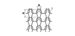
- FIG. 4 is an explanatory plan view of a mesh of reinforcing material.
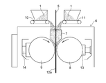
- FIG. 5 is a cross-sectional explanatory view of a method for forming a composite strip in the manufacturing process of the cylindrical gasket of the present invention.
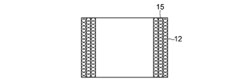
- FIG. 6 is a plan view of the cylindrical base material in the manufacturing process of the cylindrical gasket of the present invention.
- FIG. 7 is a cross-sectional explanatory view taken along the line VII-VII of the cylindrical base material shown in FIG.
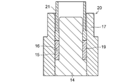
- FIG. 8 is an explanatory cross-sectional view showing a state in which a cylindrical base material is inserted into a mold in the manufacturing process of the cylindrical gasket of the present invention.
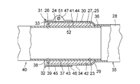
- FIG. 9 is a longitudinal cross-sectional explanatory view of a plug-in type exhaust pipe joint incorporating an example of the cylindrical gasket of the present invention.
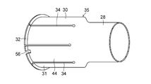
- FIG. 10 is a perspective explanatory view of the inner pipe of the plug-in type exhaust pipe joint.
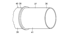
- FIG. 11 is an explanatory perspective view of the outer pipe of the plug-in type exhaust pipe joint.
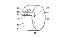
- FIG. 12 is a perspective explanatory view of a fastening band of the plug-in type exhaust pipe joint.
- the acid-treated graphite powder used for heat-resistant materials is natural graphite or artificial graphite powder, inorganic acid such as concentrated sulfuric acid, nitric acid, selenic acid and concentrated nitric acid, perchloric acid, perchlorate, permanganate, dichromic acid It is a crystalline compound that maintains a carbon layer structure obtained by acid treatment by inserting an inorganic acid between graphite layers using a strong oxidizing agent such as salt and hydrogen peroxide.
- the graphite powder used for the heat-resistant material is natural graphite powder made of at least one of scale-like graphite, earthy graphite and scale-like graphite, artificial graphite powder made of at least one of quiche graphite and pyrolytic graphite, and expanded graphite. It is selected from at least one of the powders.
- the expanded graphite powder is the above-mentioned acid-treated graphite powder heated (expanded) at a temperature of 950 to 1200 ° C. for 1 to 10 seconds to generate a decomposition gas, and the graphite layer is expanded by the gas pressure. Expanded expanded graphite powder (expansion magnification of 240 to 300 times).
- the expanded graphite powder can be used as a heat-resistant material in the present invention, but the expanded graphite powder has a bulk density as low as 0.05 g / cm 2 and is difficult to handle.
- the expanded graphite powder is supplied to a twin roll apparatus adjusted to a desired roll gap and roll-molded to produce an expanded graphite sheet having a desired thickness, and the expanded graphite sheet is cut.
- expanded graphite pulverized powder obtained by pulverization with a pulverizer as expanded graphite powder.
- end material By using the expanded graphite sheet, for example, an extra piece generated when the expanded graphite sheet is cut out along a desired mold, so-called end material, can be used effectively, thereby reducing the material cost of the expanded graphite powder. Reduction can be achieved, and as a result, the cost of the cylindrical gasket itself can be reduced.
- a mixed metal powder of graphite powder and acid-treated graphite powder serves as a reinforcing metal strip and an inorganic binder that acts as a bonding agent for holding the mesh is aluminum dihydrogen phosphate, aluminum hydrogen phosphate
- magnesium dihydrogen phosphate, magnesium hydrogen phosphate, calcium dihydrogen phosphate, calcium hydrogen phosphate and phosphoric acid is selected and used.
- the reinforcing wire mesh is made of stainless steel wire such as austenitic SUS304, SUS310S, SUS316, ferrite SUS430, iron wire (JISG3532) or galvanized iron wire (JISG3547), or copper-copper-nickel alloy (white copper).
- the fine metal wire forming the wire mesh has a wire diameter of about 0.05 to 0.50 mm.
- the wire mesh for reinforcing material knitted with the fine metal wire of the wire diameter has a mesh width (braided).
- a wire net (see FIG. 4) having a length of about 1.5 to 6.0 mm and a width of about 1.0 to 5.0 mm is preferably used.
- Natural graphite artificial graphite, natural graphite powder obtained by pulverizing expanded graphite sheet, graphite powder selected from at least one of artificial graphite powder and expanded graphite powder, and acid-treated graphite powder, aluminum dihydrogen phosphate, A predetermined ratio of at least one inorganic binder selected from aluminum hydrogen phosphate, magnesium dihydrogen phosphate, magnesium hydrogen phosphate, calcium dihydrogen phosphate, calcium hydrogen phosphate, and phosphoric acid, acid-treated graphite powder, and distilled water And kneaded to prepare a mixture 1 having wettability.
- the mass ratio of the graphite powder and the acid-treated graphite powder contained in the wettable mixture 1 is 1: 0.01 to 0.5, and the mass ratio of the inorganic binder is the mass 1 of the graphite and the acid-treated graphite. Is preferably 0.1 to 1.
- the mesh width obtained by continuously knitting a fine metal wire having a wire diameter of 0.05 to 0.50 mm with a knitting machine has a length of 1.5 to 6.0 mm and a width of A cylindrical wire mesh 2 formed of a cylindrical braided wire mesh having a thickness of about 1.0 to 5.0 mm (see FIG. 4) is passed between the pair of rollers 3 and 4 to produce a belt-like wire mesh 5 having a desired width.
- the belt-like wire mesh 5 is inserted into the hopper 7 in the rolling device 6, and the insertion end of the belt-like wire mesh 5 is passed between the pair of rollers 8 and 9.
- the mixture 1 having wettability is fed to the conveyors 10 and 11.
- the mixture 1 supplied to the hopper 7 is supplied to the band metal mesh 5 between the rollers 8 and 9, the mixture 1 is rolled between the rollers 8 and 9, and the mixture 1 is filled in the mesh of the band metal mesh 5.
- 5 and the band-like metal mesh 5 and the mixture 1 held in the mesh are produced as a single piece, and the composite band-like material 12a is wound into a roll.
- reference numeral 13 denotes a load cell arranged on one roller 8 side
- reference numeral 14 denotes a fluid cylinder arranged on the other roller 9 side.
- the composite strip-shaped material 12a wound up in a roll is dried in a drying furnace, and after removing the moisture from the mixture 1 in the composite strip-shaped material 12a by evaporating away, the composite strip-shaped material 12a is cut into a desired length, As shown in FIGS. 6 and 7, the composite strip-like material 12 obtained by cutting is wound into a spiral shape around at least two turns around a core bar (not shown), and three turns in the embodiment. A base material 15 is produced.
- a mold 20 shown in FIG. 8 having a hollow cylindrical portion 19 formed therein is prepared by fitting a stepped core 18 into the through hole 16 of the cavity 17 having the through hole 16 therein.
- the cylindrical base material 15 is inserted into the stepped core 18.
- the cylindrical base material 15 inserted into the hollow cylindrical portion 19 of the mold 20 is compression-molded with a punch 21 in the core axial direction at a pressure of 98 to 294 N / mm 2 (1 to 3 tons / cm 2 ), and FIG.
- a cylindrical gasket 27 having a cylindrical inner peripheral surface 23 that defines the through-hole 22, a cylindrical outer peripheral surface 24, and annular end surfaces 25 and 26 is produced.
- a cylindrical gasket 27 produced by compression molding of the cylindrical base material 15 includes a reinforcing material 70 made of a compressed band-shaped metal mesh 5, and a compressed acid filled in the mesh of the band-shaped metal mesh 5 of the reinforcing material 70.
- a heat-resistant material 71 made of a treated graphite powder, a mixture 1 of graphite powder and an inorganic binder, and a reinforcing material 70 and pores distributed in the heat-resistant material 71 are provided.
- the reinforcing members 70 are intertwined with each other and have structural integrity.
- the reinforcing member 70 is densely contained in the radial direction from the cylindrical inner peripheral surface 23 to the cylindrical outer peripheral surface 24, and the inner periphery of the cylindrical gasket 27.
- the surface 23, the outer peripheral surface 24, and the annular end surfaces 25 and 26 are smooth surfaces in which the heat-resistant material 71 and the reinforcing material 70 are mixed.
- the amount of the pore content contained in the cylindrical gasket 27 is related to the sealing performance of the cylindrical gasket 27.
- the pore content is less than 10% by volume, the cylindrical gasket 27 itself.
- the initial conformability with the inner peripheral surface of the exhaust pipe is poor, and as a result, the sealing performance may be lowered.
- the content ratio of the pores contained in the cylindrical gasket 27 is preferably 10 to 35%, more preferably 15 to 30% in volume ratio.
- the cylindrical gasket 27 is used by being incorporated in a plug-in type exhaust pipe joint shown in FIG.
- the plug-in type exhaust pipe joint shown in FIG. 9 includes a pipe end portion 28, an enlarged diameter cylindrical portion 30 formed by expanding the diameter of the pipe end portion 28 via a tapered annular shoulder portion 29, An opening end 31 formed at one end in the axial direction, a flange 32 formed on the outer peripheral surface of the opening end 31 and extending radially outward, and an opening end at the enlarged-diameter cylindrical portion 30 and the flange 32 An outer tube 35 (see FIGS.
- a fastening band 45 having a pair of ears 47 and 48 integrally projecting radially outward from the cylindrical body 46
- the diameter of the cylindrical body 46 is reduced by tightening a fastener 51 such as a bolt inserted into the through holes 49 and 50 of the ear portions 47 and 48, and the diameter-enlarged cylinder of the outer tube 35 is passed through the inner peripheral surface 52 of the cylindrical body 46.
- the cylindrical inner surface 42 of the cylindrical gasket 27 is pressed against the cylindrical outer peripheral surface 24 of the cylindrical gasket 27, and the cylindrical inner peripheral surface 23 of the cylindrical gasket 27 is pressed against the cylindrical outer surface of the tube end 37 of the inner tube 40.
- the cylindrical gasket 27 is disposed in the annular space 43 such that one end face 26 in the axial direction is in contact with the flange 39 of the inner tube 40.
- the annular space 43 between the tube 40 and the outer tube 35 is sealed to prevent the exhaust gas from leaking from the annular space 43.
- one end 53 of the end portions 53 and 54 in the axial direction of the fastening band 45 is provided with a hook portion 55 projecting radially inward
- the hook portion 55 having a cross section similar to the notch portion 56 formed in the flange portion 32 of the enlarged diameter cylindrical portion 30 of the outer tube 35 has a fastening band 45 of the enlarged diameter cylindrical portion 30 of the outer tube 35.
- the outer tube 35 is engaged with the fastening band 45 in the flange portion 32 in the axial direction, so that the inner tube 40 and the outer tube 35 are subjected to inner force even if a force acting in the axial direction is applied to the inner tube 40 and the outer tube 35.
- the tube 40 and the outer tube 35 are not separated.
- the cylindrical gasket 27 used by being incorporated in the plug-in type exhaust pipe joint is volume-expanded by the heat of the exhaust gas flowing in the inner pipe 40 of the exhaust pipe joint, and the cylindrical outer peripheral surface 24 of the cylindrical gasket 27 and The cylindrical inner surface 42 of the enlarged diameter cylindrical portion 30 of the outer tube 35 is in close contact, and the cylindrical inner peripheral surface 23 of the cylindrical gasket 27 and the cylindrical outer surface 41 of the tube end 37 of the inner tube 40 are in close contact.
- the cylindrical gasket 27 with increased rigidity does not cause settling or the like due to a large tightening force by the fastening band 45, and the fastening force is loosened due to a decrease in the tightening force on the fastening band 45. Therefore, the hook portion 55 formed in the fastening band 45 and the notch portion 56 formed in the flange portion 32 of the outer tube 35 are not necessarily provided.
- Example 1 As acid-treated graphite powder, a 60% aqueous solution of hydrogen peroxide as a strong oxidant is added while stirring concentrated sulfuric acid having a concentration of 98% to make a reaction solution, and the reaction solution is cooled and maintained at a temperature of 10 ° C. Then, a scale-like natural graphite powder having a particle size of 30 to 80 mesh is added to the reaction liquid and reacted for 30 minutes, followed by suction filtration to separate the acid-treated graphite powder.
- a 60% aqueous solution of hydrogen peroxide as a strong oxidant is added while stirring concentrated sulfuric acid having a concentration of 98% to make a reaction solution, and the reaction solution is cooled and maintained at a temperature of 10 ° C. Then, a scale-like natural graphite powder having a particle size of 30 to 80 mesh is added to the reaction liquid and reacted for 30 minutes, followed by suction filtration to separate the acid-treated graphite powder.
- the washing operation of stirring for a minute and suction filtration was repeated twice, and the sulfuric acid content was sufficiently removed from the acid-treated graphite, and the acid-treated graphite powder from which sulfuric acid had been sufficiently removed was dried for 3 hours in a drying furnace maintained at a temperature of 110 ° C.
- the acid-treated graphite powder obtained above was used.
- an expanded graphite powder obtained by cutting and pulverizing an expanded graphite sheet having a density of 1.12 Mg / m 3 and a thickness of 0.4 mm was used.
- magnesium hydrogen phosphate (secondary magnesium phosphate) was used as the inorganic binder.
- the expanded graphite powder and the acid-treated graphite powder are mixed at a mass ratio of 1: 0.01, and magnesium hydrogen phosphate and distilled water are added to 0.25 with respect to the mass 1 of the expanded graphite powder and the acid-treated graphite powder. : Blended at a mass ratio of 0.75, and kneaded these to prepare a mixture having wettability.
- a cylindrical braided wire net having a mesh width of about 2.0 mm and a width of about 1.5 mm is prepared using seven austenitic stainless steel wires (SUS304) having a wire diameter of 0.15 mm as thin metal wires. This was passed between a pair of rollers to form a band metal mesh for reinforcing material.
- SUS304 austenitic stainless steel wires
- a strip metal mesh is inserted into the hopper of the rolling device, the insertion end of the strip metal mesh is passed between a pair of rolling rollers, and the hopper divided into two by the strip metal mesh is used.
- a mixture having wettability is supplied from a conveyor, and the mixture supplied in the hopper is supplied to both sides of the belt-like wire mesh.
- the mixture is fed between the rolling rollers, and the mixture is rolled between the rolling rollers.
- a composite belt-like material in which the mixture filled and held in the mesh was integrated.
- the composite strip material is dried in a drying oven to evaporate and dissipate the water contained in the mixture, and then the dried composite strip material is cut to a composite strip material having a width of about 63 mm and a length of about 175 mm (composite strip shape)
- the mass of the material 32.7 g
- the mass of the strip metal mesh in the composite strip material 27.2 g
- the expanded graphite powder 4.36 g
- the acid-treated graphite powder 0.04 g
- magnesium hydrogen phosphate 1.1 g The mass of the material: 32.7 g
- the mass of the strip metal mesh in the composite strip material 27.2 g
- the expanded graphite powder 4.36 g
- the acid-treated graphite powder 0.04 g
- magnesium hydrogen phosphate 1.1 g The mass of the material: 32.7 g
- the mass of the strip metal mesh in the composite strip material 27.2 g
- the expanded graphite powder 4.36 g
- the acid-treated graphite powder 0.04 g
- This cylindrical strip was wound twice around the outer peripheral surface of a cylindrical core bar in a spiral manner to produce a cylindrical base material.
- the cylindrical base material was inserted into the stepped core of the mold shown in FIG. 8 in which the hollow cylindrical portion was formed by fitting the stepped core into the through hole of the cavity having the through hole on the inner surface.
- the cylindrical base material arranged in the hollow cylindrical part of the mold is compression-molded with a pressure of 196 N / mm 2 (2 ton / cm 2 ) in the core axial direction, and the cylindrical inner peripheral surface defining the through hole and the cylindrical shape
- a cylindrical gasket having an inner diameter of 22.1 mm, an outer diameter of 29.35 mm, and a length of 25 mm was prepared.
- the content ratios of the reinforcing material, the heat-resistant material, and the pores were 46.9%, 34.4%, and 18.7% in volume ratio, respectively.
- Example 2 As the acid-treated graphite powder, the same acid-treated graphite powder as in Example 1 is used, as the graphite powder, the expanded graphite powder as in Example 1 is used, and as the inorganic binder, as in Example 1 above. Magnesium hydrogen phosphate was used.
- the expanded graphite powder and the acid-treated graphite powder are blended at a mass ratio of 1: 0.05, and magnesium hydrogen phosphate and distilled water are added at 0.18: 0 to the mass 1 of the expanded graphite powder and the acid-treated graphite powder.
- the mixture was blended at a mass ratio of .82 and kneaded to prepare a mixture having wettability.
- band metal mesh for the reinforcing material the same band metal mesh as in Example 1 was used.
- a composite strip material was prepared in the same manner as in Example 1 using a wettable mixture and a strip wire mesh.
- the composite strip material is dried in a drying oven to evaporate and dissipate the water contained in the mixture, and then the dried composite strip material is cut to a composite strip material having a width of about 63 mm and a length of about 175 mm (composite strip shape)
- the mass of the material 31.92 g
- the mass of the strip metal mesh in the composite strip material 27.2 g
- the expanded graphite powder 3.81 g
- the acid-treated graphite powder 0.19 g
- magnesium hydrogen phosphate 0.72 g The mass of the material: 31.92 g, the mass of the strip metal mesh in the composite strip material: 27.2 g, the expanded graphite powder: 3.81 g, the acid-treated graphite powder: 0.19 g, and the magnesium hydrogen phosphate 0.72 g).
- a cylindrical base material is produced by winding the composite strip material in a spiral manner around the outer peripheral surface of a cylindrical metal core to produce a cylindrical base material, and defining a through hole in the same manner as in the first embodiment.
- a cylindrical gasket having an inner diameter of 22.1 mm, an outer diameter of 29.35 mm, and a length of 25 mm, having a surface, a cylindrical outer peripheral surface, and an annular end surface was produced.
- the contents of the reinforcing material, the heat-resistant material, and the pores were 46.9%, 29.4%, and 23.7%, respectively, in volume ratio.
- Example 3 As the acid-treated graphite powder, the same acid-treated graphite powder as in Example 1 was used. As the graphite powder, the same expanded graphite powder as in Example 1 was used. As the inorganic binder, aluminum dihydrogen phosphate was used. .
- the expanded graphite powder and the acid-treated graphite powder are blended at a mass ratio of 1: 0.1, and aluminum dihydrogen phosphate and distilled water are added to the mass 1 of the expanded graphite powder and the acid-treated graphite powder at 0.25:
- the mixture was blended at a mass ratio of 0.75, and these were kneaded to prepare a mixture having wettability.
- band metal mesh for the reinforcing material the same band metal mesh as in Example 1 was used.
- a composite strip material was prepared in the same manner as in Example 1 using a wettable mixture and a strip wire mesh.
- the composite strip material is dried in a drying furnace to evaporate and dissipate the moisture contained in the mixture, and then the composite strip material is cut to obtain a composite strip material having a width of about 63 mm and a length of about 175 mm (the mass of the composite strip material). 32.2 g, the mass of the strip wire mesh in the composite strip material: 27.2 g, the expanded graphite powder: 3.64 g, the acid-treated graphite powder: 0.36 g, and the aluminum dihydrogen phosphate: 1 g).
- a cylindrical base material is produced by winding the composite strip material in a spiral manner around the outer peripheral surface of a cylindrical metal core to produce a cylindrical base material, and defining a through hole in the same manner as in the first embodiment.
- a cylindrical gasket having an inner diameter of 22.1 mm, an outer diameter of 29.35 mm, and a length of 25 mm, having a surface, a cylindrical outer peripheral surface, and an annular end surface was produced.
- the content ratios of the reinforcing material, the heat-resistant material, and the pores were 46.9%, 33.9%, and 19.2% in volume ratio, respectively.
- Example 4 As the acid-treated graphite powder, the same acid-treated graphite powder as in Example 1 was used. As the graphite powder, the same expanded graphite powder as in Example 1 was used. As the inorganic binder, aluminum dihydrogen phosphate (1st Aluminum phosphate) was used.
- the expanded graphite powder and the acid-treated graphite powder are blended at a mass ratio of 1: 0.3, and the mass of the expanded graphite powder and the acid-treated graphite powder is 0.25:
- the mixture was blended at a mass ratio of 0.75, and these were kneaded to prepare a mixture having wettability.
- band metal mesh for the reinforcing material the same band metal mesh as in Example 1 was used.
- a composite strip material was prepared in the same manner as in Example 1 using a wettable mixture and a strip wire mesh.
- the composite strip material is dried in a drying furnace to evaporate and dissipate the moisture contained in the mixture, and then the composite strip material is cut to obtain a composite strip material having a width of about 63 mm and a length of about 175 mm (the mass of the composite strip material). 32.7 g, the mass of the strip wire mesh in the composite strip material: 27.2 g, the expanded graphite powder: 3.38 g, the acid-treated graphite powder: 1.02 g, and the aluminum dihydrogen phosphate: 1.1 g).
- a cylindrical base material is produced by winding the composite strip material in a spiral manner around the outer peripheral surface of a cylindrical metal core to produce a cylindrical base material, and defining a through hole in the same manner as in the first embodiment.
- a cylindrical gasket having an inner diameter of 22.1 mm, an outer diameter of 29.35 mm, and a length of 25 mm, having a surface, a cylindrical outer peripheral surface, and an annular end surface was produced.
- the content ratios of the reinforcing material, the heat-resistant material, and the pores were 46.9%, 34.8%, and 18.3% by volume ratio, respectively.
- Example 5 As the acid-treated graphite powder, the same acid-treated graphite powder as in Example 1 is used, as the graphite powder, the expanded graphite powder as in Example 1 is used, and as the inorganic binder, calcium dihydrogen phosphate (first Calcium phosphate) was used.
- first Calcium phosphate first Calcium phosphate
- the expanded graphite powder and the acid-treated graphite powder are blended at a mass ratio of 1: 0.2, and calcium dihydrogen phosphate and distilled water are added to the mass 1 of the expanded graphite powder and the acid-treated graphite powder at 0.25:
- the mixture was blended at a mass ratio of 0.75, and these were kneaded to prepare a mixture having wettability.
- band metal mesh for the reinforcing material the same band metal mesh as in Example 1 was used.
- a composite strip material was prepared in the same manner as in Example 1 using a wettable mixture and a strip wire mesh.
- the composite strip material is dried in a drying furnace to evaporate and dissipate the moisture contained in the mixture, and then the composite strip material is cut to obtain a composite strip material having a width of about 63 mm and a length of about 175 mm (the mass of the composite strip material). 32.7 g, mass of the strip wire mesh in the composite strip material: 27.2 g, expanded graphite powder: 3.67 g, acid-treated graphite powder: 0.73 g, calcium dihydrogen phosphate: 1.1 g).
- a cylindrical base material is produced by winding the composite strip material in a spiral manner around the outer peripheral surface of a cylindrical metal core to produce a cylindrical base material, and defining a through hole in the same manner as in the first embodiment.
- a cylindrical gasket having an inner diameter of 22.1 mm, an outer diameter of 29.35 mm, and a length of 25 mm, having a surface, a cylindrical outer peripheral surface, and an annular end surface was produced.
- the content ratios of the reinforcing material, the heat-resistant material, and the pores were 46.9%, 34.0%, and 19.1% in volume ratio, respectively.
- Example 6 As the acid-treated graphite powder, the same acid-treated graphite powder as in Example 1 was used. As the graphite powder, the same expanded graphite powder as in Example 1 was used. As the inorganic binder, calcium hydrogen phosphate (second phosphoric acid) was used. Calcium) was used.
- the expanded graphite powder and the acid-treated graphite powder are blended in a mass ratio of 1: 0.1, and calcium hydrogen phosphate and distilled water are added in an amount of 0.2:
- the mixture was blended at a mass ratio of 0.8 and kneaded to prepare a mixture having wettability.
- band metal mesh for the reinforcing material the same band metal mesh as in Example 1 was used.
- a composite strip material was prepared in the same manner as in Example 1 using a wettable mixture and a strip wire mesh.
- the composite strip material is dried in a drying furnace to evaporate and dissipate the moisture contained in the mixture, and then the composite strip material is cut to obtain a composite strip material having a width of about 63 mm and a length of about 175 mm (the mass of the composite strip material). 32.0 g, the mass of the strip wire mesh in the composite strip material: 27.2 g, expanded graphite powder: 3.64 g, acid-treated graphite powder: 0.36 g, calcium hydrogen phosphate: 0.8 g).
- a cylindrical base material is produced by winding the composite strip material in a spiral manner around the outer peripheral surface of a cylindrical metal core to produce a cylindrical base material, and defining a through hole in the same manner as in the first embodiment.
- a cylindrical gasket having an inner diameter of 22.1 mm, an outer diameter of 29.35 mm, and a length of 25 mm, having a surface, a cylindrical outer peripheral surface, and an annular end surface was produced.
- the content ratios of the reinforcing material, the heat-resistant material, and the pores were 46.9%, 29.4%, and 23.7%, respectively, in volume ratio.
- Example 7 As the acid-treated graphite powder, the same acid-treated graphite powder as in Example 1 was used. As the graphite powder, the same expanded graphite powder as in Example 1 was used. As the inorganic binder, phosphoric acid (H 3 PO 4 : 75% aqueous solution) was used.
- phosphoric acid H 3 PO 4 : 75% aqueous solution
- the expanded graphite powder and the acid-treated graphite powder are blended at a mass ratio of 1: 0.3, and phosphoric acid is blended at a mass ratio of 0.25 to the mass 1 of the expanded graphite powder and the acid-treated graphite powder. These were kneaded to prepare a wettable mixture.
- band metal mesh for the reinforcing material the same band metal mesh as in Example 1 was used.
- a composite strip material was prepared in the same manner as in Example 1 using a wettable mixture and a strip wire mesh.
- the composite strip material is dried in a drying furnace to evaporate and dissipate the moisture contained in the mixture, and then the composite strip material is cut to obtain a composite strip material having a width of about 63 mm and a length of about 175 mm (the mass of the composite strip material). 32.2 g, the mass of the strip wire mesh in the composite strip material: 27.2 g, the expanded graphite powder: 3.1 g, the acid-treated graphite powder: 0.9 g, and the phosphoric acid: 1 g).
- a cylindrical base material is produced by winding the composite strip material in a spiral manner around the outer peripheral surface of a cylindrical metal core to produce a cylindrical base material, and defining a through hole in the same manner as in the first embodiment.
- a cylindrical gasket having an inner diameter of 22.1 mm, an outer diameter of 29.35 mm, and a length of 25 mm, having a surface, a cylindrical outer peripheral surface, and an annular end surface was produced.
- the content ratios of the reinforcing material, the heat-resistant material, and the pores were 46.9%, 32.4%, and 20.7% in volume ratio, respectively.
- Example 8 As the acid-treated graphite powder, the same acid-treated graphite powder as in Example 1 is used, as the graphite powder, the expanded graphite powder as in Example 1 is used, and as the inorganic binder, as in Example 1 above. Magnesium hydrogen phosphate was used.
- the expanded graphite powder and the acid-treated graphite powder are blended at a mass ratio of 1: 0.5, and magnesium hydrogen phosphate and distilled water are added in an amount of 0.25 with respect to the mass 1 of the expanded graphite powder and the acid-treated graphite powder. : Blended at a mass ratio of 0.75, and kneaded these to prepare a mixture having wettability.
- band metal mesh for the reinforcing material the same band metal mesh as in Example 1 was used.
- a composite strip material was prepared in the same manner as in Example 1 using a wettable mixture and a strip wire mesh.
- the composite strip material is dried in a drying furnace to evaporate and dissipate the moisture contained in the mixture, and then the composite strip material is cut to obtain a composite strip material having a width of about 63 mm and a length of about 175 mm (the mass of the composite strip material).
- mass of the strip wire mesh in the composite strip material 27.2 g
- expanded graphite powder 2.67 g
- acid-treated graphite powder 1.33 g
- magnesium hydrogen phosphate 1.0 g).
- a cylindrical base material is produced by winding the composite strip material in a spiral manner around the outer peripheral surface of a cylindrical metal core to produce a cylindrical base material, and defining a through hole in the same manner as in the first embodiment.
- a cylindrical gasket having an inner diameter of 22.1 mm, an outer diameter of 29.35 mm, and a length of 25 mm, having a surface, a cylindrical outer peripheral surface, and an annular end surface was produced.
- the contents of the reinforcing material, the heat-resistant material, and the pores were 46.9%, 31.3%, and 21.8%, respectively, in volume ratio.
- Comparative Example 1 An expanded graphite sheet piece for a strip-shaped heat-resistant material having a density of 1.2 Mg / m 3 and a thickness of 0.4 mm cut to a width of 75 mm and a length of 257 mm was prepared.
- a cylindrical braided wire mesh having a mesh width of about 4.00 mm and a width of about 3.0 mm is prepared.
- a continuous strip metal mesh having a width of 68 mm was passed through a pair of rollers, and the strip metal mesh was cut into a length of 257 mm, which was used as a reinforcing strip metal mesh.
- the expanded graphite sheet piece protrudes in the width direction from both end edges in the width direction of the band metal mesh for reinforcing material which becomes the annular end face of the cylindrical gasket, and one end edge in the length direction of the expanded graphite sheet piece and the end
- the expanded graphite sheet piece corresponding to the end edge was matched with the edge in the length direction to produce a polymer in which the expanded graphite sheet piece and the belt-shaped wire mesh were overlapped with each other.
- the polymer On the outer peripheral surface of the cylindrical metal core, the polymer is spirally wound with the expanded graphite sheet piece on the inner side, and the expanded graphite sheet piece is wound one turn, and the inner peripheral surface side and the outer peripheral surface side.
- a cylindrical base material with an expanded graphite sheet piece exposed on both was prepared. In this cylindrical base material, both end portions of the expanded graphite sheet piece in the width direction protrude (extrude) in the width direction of the belt-shaped wire mesh.
- a mold shown in FIG. 8 having a hollow cylindrical portion formed therein by fitting a stepped core into the through hole of the cavity having a through hole on the inner surface is prepared, and the stepped core of the mold has a cylindrical shape Inserted the base material.
- the cylindrical base material arranged in the hollow cylindrical part of the mold is compression-molded with a pressure of 196 N / mm 2 (2 ton / cm 2 ) in the core axial direction, and the cylindrical inner peripheral surface defining the through hole and the cylindrical shape
- a cylindrical gasket having an inner diameter of 22.1 mm, an outer diameter of 29.4 mm, and a length of 25 mm was prepared.
- the content of the heat-resistant material and the pores made of the expanded graphite sheet piece compressed in the same manner as the reinforcing material made of the compressed strip-shaped wire mesh is 9.8% of the reinforcing material by volume ratio, and the heat-resistant material 49 0.6% and 40.5% porosity.
- Comparative Example 2 The same expanded graphite sheet piece for heat-resistant materials as in Comparative Example 1 was prepared.
- a cylindrical gasket having an inner diameter of 22.1 mm, an outer diameter of 29.4 mm, and a length of 25 mm was produced in the same manner as in Comparative Example 1.
- the volume ratio of the reinforcing material, the heat-resistant material, and the pores was 43.4% for the reinforcing material, 15.1% for the heat-resistant material, and 41.5% for the pores, respectively.
- ⁇ Test method for gas leakage> The temperature is raised to 500 ° C. over 1 hour while continuing the rocking motion of ⁇ 0.5 ° at an excitation frequency of 50 Hz at room temperature (25 ° C.), and the rocking motion is performed while maintaining the temperature for 22 hours. After 22 hours, the temperature was lowered to room temperature in 1 hour, and the amount of gas leakage at room temperature (before starting the test) and the amount of gas leakage after 24 hours of test time were measured.
- ⁇ Measurement method of gas leakage> The opening of the outer pipe of the plug-in type exhaust pipe joint shown in FIG. 9 is closed, and dry air flows in from the inner pipe side at a pressure of 30 kPa, from the joint part (the gap between the inner pipe and the outer pipe). The amount of gas leakage was measured twice with a flow meter (1) at the beginning of the test (immediately after the start of the test) and (2) after 24 hours.
- the cylindrical gaskets of Examples 1 to 8 are more than the cylindrical gaskets of Comparative Example 1 and Comparative Example 2 in terms of gas leakage and tightening torque reduction rate. It turns out that it is excellent.
- the amount of gas leakage of the cylindrical gasket of each example tended to be larger than the amount of gas leakage of the cylindrical gasket of Comparative Example 1 immediately after the start of the test, but the amount of gas leakage of the cylindrical gasket of each example Showed a decreasing tendency with the lapse of the test time, and the gas leakage after 24 hours was extremely low.
- the cylindrical gasket made of Comparative Example 1 showed a tendency for the amount of gas leakage to increase with the lapse of the test time. This was because the decrease rate of the tightening torque decreased to less than half of the initial value, and the cylindrical gasket This is presumably because the gap between the two was increased due to settling in the gasket. Further, the cylindrical gasket of Comparative Example 2 is a gasket specialized in rigidity, and the decrease rate of the tightening torque was not significantly different from the cylindrical gasket of each Example, but it was 24 immediately after the start of the test. The amount of gas leakage tended to increase throughout the test time after the passage of time.
- the cylindrical gasket of the present invention has a structural integrity because the reinforcing material and the heat-resistant material are intertwined with each other, and the reinforcing material extends in the radial direction from the cylindrical inner peripheral surface to the cylindrical outer peripheral surface. Tightened with a fastening band because the content of the reinforcing material, the heat-resistant material and the pores is 32 to 60%, the heat-resistant material is 5 to 58% and the pores are 10 to 35% by volume.
- the cylindrical gasket of the present invention is incorporated in a plug-in type exhaust pipe joint and does not cause problems such as settling even if it is firmly tightened by a fastening band. Even in the case of repeated twisting between the torque and the inner and outer pipes, gas leakage from the joint part of the exhaust pipe can be prevented as much as possible.
Landscapes
- Engineering & Computer Science (AREA)
- General Engineering & Computer Science (AREA)
- Mechanical Engineering (AREA)
- Chemical & Material Sciences (AREA)
- Combustion & Propulsion (AREA)
- Gasket Seals (AREA)
- Exhaust Silencers (AREA)
- Joints With Sleeves (AREA)
Priority Applications (6)
| Application Number | Priority Date | Filing Date | Title |
|---|---|---|---|
| US14/358,971 US9347562B2 (en) | 2011-11-30 | 2012-11-20 | Cylindrical gasket, method for manufacturing the same, and insertion-type exhaust pipe joint using the cylindrical gasket |
| IN3518CHN2014 IN2014CN03518A (https=) | 2011-11-30 | 2012-11-20 | |
| CN201280058802.7A CN103958847B (zh) | 2011-11-30 | 2012-11-20 | 圆筒形垫圈及其制造方法以及相关的插入型排气管接头 |
| BR112014011086A BR112014011086A2 (pt) | 2011-11-30 | 2012-11-20 | gaxeta cilíndrica, método para fabricar a mesma, e junta de cano de escape do tipo de inserção usando a gaxeta cilíndrica |
| CA2853968A CA2853968C (en) | 2011-11-30 | 2012-11-20 | Cylindrical gasket, method for manufacturing the same, and insertion-type exhaust pipe joint using the cylindrical gasket |
| EP12854412.9A EP2787188A4 (en) | 2011-11-30 | 2012-11-20 | CYLINDRICAL SEAL, MANUFACTURING METHOD AND SEPARATE EXHAUST PIPE CONNECTOR WITH THE CYLINDRICAL SEAL |
Applications Claiming Priority (2)
| Application Number | Priority Date | Filing Date | Title |
|---|---|---|---|
| JP2011-262740 | 2011-11-30 | ||
| JP2011262740A JP5884447B2 (ja) | 2011-11-30 | 2011-11-30 | 円筒状ガスケット及びその製造方法並びに該円筒状ガスケットを使用した差し込み型排気管継手 |
Publications (1)
| Publication Number | Publication Date |
|---|---|
| WO2013080487A1 true WO2013080487A1 (ja) | 2013-06-06 |
Family
ID=48534984
Family Applications (1)
| Application Number | Title | Priority Date | Filing Date |
|---|---|---|---|
| PCT/JP2012/007444 Ceased WO2013080487A1 (ja) | 2011-11-30 | 2012-11-20 | 円筒状ガスケット及びその製造方法並びに該円筒状ガスケットを使用した差し込み型排気管継手 |
Country Status (8)
| Country | Link |
|---|---|
| US (1) | US9347562B2 (https=) |
| EP (1) | EP2787188A4 (https=) |
| JP (1) | JP5884447B2 (https=) |
| CN (1) | CN103958847B (https=) |
| BR (1) | BR112014011086A2 (https=) |
| CA (1) | CA2853968C (https=) |
| IN (1) | IN2014CN03518A (https=) |
| WO (1) | WO2013080487A1 (https=) |
Families Citing this family (7)
| Publication number | Priority date | Publication date | Assignee | Title |
|---|---|---|---|---|
| JP6003062B2 (ja) * | 2012-01-12 | 2016-10-05 | オイレス工業株式会社 | 排気管球面継手 |
| JP2016196909A (ja) * | 2015-04-02 | 2016-11-24 | オイレス工業株式会社 | 円筒状ガスケット及びそれを使用した差し込み型排気管継手 |
| PL3372293T3 (pl) * | 2017-03-07 | 2021-11-29 | Dipl.-Ing. Erich Fetzer GmbH & Co. KG | Filtr taśmowy |
| JP6954042B2 (ja) * | 2017-11-21 | 2021-10-27 | 株式会社デンソー | 添加弁の取付構造 |
| CN109093118B (zh) * | 2018-07-11 | 2021-04-06 | 林耀军 | 喷射成形快速制造模具的设备及制造模具的方法 |
| US11181004B2 (en) * | 2020-02-07 | 2021-11-23 | Raytheon Technologies Corporation | Confinement of a rope seal about a passage using a backing plate |
| CN117249203B (zh) * | 2022-06-09 | 2026-04-07 | 振锋企业股份有限公司 | 钢索钩 |
Citations (6)
| Publication number | Priority date | Publication date | Assignee | Title |
|---|---|---|---|---|
| JPS61244815A (ja) | 1985-04-22 | 1986-10-31 | Honda Motor Co Ltd | 排気管継手 |
| JPH0547620U (ja) | 1991-11-29 | 1993-06-25 | 有限会社浜松ガスケット製作所 | 環状ガスケット |
| JPH06146875A (ja) | 1992-11-16 | 1994-05-27 | Suzuki Motor Corp | 自動二輪車の排気装置 |
| JPH0636273Y2 (ja) | 1988-02-26 | 1994-09-21 | フタバ産業株式会社 | 排気管継手 |
| JP2003206739A (ja) * | 2002-01-15 | 2003-07-25 | Oiles Ind Co Ltd | 球帯状シール体 |
| JP2004003604A (ja) * | 2002-04-18 | 2004-01-08 | Hamamatsu Gasket Corp | 排気管用ガスケットおよびそれを備えた排気管継手 |
Family Cites Families (25)
| Publication number | Priority date | Publication date | Assignee | Title |
|---|---|---|---|---|
| JPS5313610A (en) * | 1976-07-23 | 1978-02-07 | Nippon Carbon Co Ltd | Compound sheet materials |
| US4516782A (en) * | 1977-11-30 | 1985-05-14 | Metex Corporation | Method of producing high temperature composite seal |
| US4383694A (en) * | 1981-03-09 | 1983-05-17 | Raimondi S.P.A. | Gasket for statically sealing high pressure and temperature fluids |
| US4423544A (en) * | 1981-11-06 | 1984-01-03 | Felt Products Mfg. Co. | Method of making composite gasket |
| DE3234376C1 (de) * | 1982-09-16 | 1984-03-01 | Goetze Ag, 5093 Burscheid | Dichtungsring |
| JPS5983830A (ja) * | 1982-11-05 | 1984-05-15 | Honda Motor Co Ltd | しゆう動体 |
| US4462603A (en) * | 1983-03-16 | 1984-07-31 | Metex Corporation | Knitted wire mesh exhaust coupling seal with refractory metallic oxide impregnant |
| US4514458A (en) * | 1983-11-09 | 1985-04-30 | Lord Corporation | Spring-like material formed of compressed metallic wire |
| US4601476A (en) * | 1984-11-28 | 1986-07-22 | Metex Corporation | Squeak free seal for exhaust couplings |
| DE3512751C2 (de) * | 1985-04-10 | 1987-02-26 | Goetze Ag, 5093 Burscheid | Dichtungsring |
| US4871181A (en) * | 1987-04-09 | 1989-10-03 | Metex Corporation | Reinforced squeak free seal for exhaust couplings |
| JPH07101065B2 (ja) * | 1988-01-19 | 1995-11-01 | オイレス工業株式会社 | 排気管継手用球面シール体の製造方法 |
| US5451064A (en) * | 1992-12-22 | 1995-09-19 | Ucar Carbon Technology Corporation | Exhaust seal ring |
| US6025018A (en) * | 1997-03-25 | 2000-02-15 | Metex Mfg. Corporation | Method and apparatus for making wire mesh preform |
| JP3259903B2 (ja) * | 1997-07-14 | 2002-02-25 | 大同メタル工業株式会社 | 筒形パッキンおよびその製造方法 |
| JP4617521B2 (ja) * | 1999-09-28 | 2011-01-26 | オイレス工業株式会社 | 球帯状シール体ならびにその製造方法 |
| JP2002267019A (ja) * | 2001-03-05 | 2002-09-18 | Honda Motor Co Ltd | 高温継手部用ガスケットおよびその製造方法 |
| JP2003097718A (ja) * | 2001-09-21 | 2003-04-03 | Oiles Ind Co Ltd | 球帯状シール体及びその製造方法 |
| DE10316262A1 (de) * | 2003-04-08 | 2004-11-11 | Sgl Carbon Ag | Dichtung für Flanschverbindungen |
| WO2007018173A1 (ja) * | 2005-08-09 | 2007-02-15 | Best Corporation | 排気管球面継手用環状シール体及びその製造方法 |
| JP5000466B2 (ja) * | 2007-11-28 | 2012-08-15 | イビデン株式会社 | 排気管 |
| EP2216570B1 (en) * | 2007-12-05 | 2015-07-22 | Oiles Corporation | Spherical annular seal and process for production thereof |
| JP2010018831A (ja) * | 2008-07-09 | 2010-01-28 | Ibiden Co Ltd | 受熱部材、及び、排気管放熱システム |
| JP5760364B2 (ja) * | 2010-08-19 | 2015-08-12 | オイレス工業株式会社 | 球帯状シール体 |
| JP5834806B2 (ja) | 2011-11-17 | 2015-12-24 | オイレス工業株式会社 | 円筒状ガスケット及びその製造方法並びに該円筒状ガスケットを使用した差し込み型排気管継手 |
-
2011
- 2011-11-30 JP JP2011262740A patent/JP5884447B2/ja active Active
-
2012
- 2012-11-20 EP EP12854412.9A patent/EP2787188A4/en not_active Withdrawn
- 2012-11-20 IN IN3518CHN2014 patent/IN2014CN03518A/en unknown
- 2012-11-20 US US14/358,971 patent/US9347562B2/en active Active
- 2012-11-20 CN CN201280058802.7A patent/CN103958847B/zh active Active
- 2012-11-20 BR BR112014011086A patent/BR112014011086A2/pt not_active Application Discontinuation
- 2012-11-20 WO PCT/JP2012/007444 patent/WO2013080487A1/ja not_active Ceased
- 2012-11-20 CA CA2853968A patent/CA2853968C/en active Active
Patent Citations (6)
| Publication number | Priority date | Publication date | Assignee | Title |
|---|---|---|---|---|
| JPS61244815A (ja) | 1985-04-22 | 1986-10-31 | Honda Motor Co Ltd | 排気管継手 |
| JPH0636273Y2 (ja) | 1988-02-26 | 1994-09-21 | フタバ産業株式会社 | 排気管継手 |
| JPH0547620U (ja) | 1991-11-29 | 1993-06-25 | 有限会社浜松ガスケット製作所 | 環状ガスケット |
| JPH06146875A (ja) | 1992-11-16 | 1994-05-27 | Suzuki Motor Corp | 自動二輪車の排気装置 |
| JP2003206739A (ja) * | 2002-01-15 | 2003-07-25 | Oiles Ind Co Ltd | 球帯状シール体 |
| JP2004003604A (ja) * | 2002-04-18 | 2004-01-08 | Hamamatsu Gasket Corp | 排気管用ガスケットおよびそれを備えた排気管継手 |
Non-Patent Citations (1)
| Title |
|---|
| See also references of EP2787188A4 |
Also Published As
| Publication number | Publication date |
|---|---|
| EP2787188A4 (en) | 2015-10-07 |
| CA2853968A1 (en) | 2013-06-06 |
| US9347562B2 (en) | 2016-05-24 |
| BR112014011086A2 (pt) | 2017-05-16 |
| JP2013113416A (ja) | 2013-06-10 |
| EP2787188A1 (en) | 2014-10-08 |
| JP5884447B2 (ja) | 2016-03-15 |
| IN2014CN03518A (https=) | 2015-07-03 |
| CN103958847B (zh) | 2016-08-24 |
| CA2853968C (en) | 2015-12-29 |
| US20140312572A1 (en) | 2014-10-23 |
| CN103958847A (zh) | 2014-07-30 |
Similar Documents
| Publication | Publication Date | Title |
|---|---|---|
| JP5884447B2 (ja) | 円筒状ガスケット及びその製造方法並びに該円筒状ガスケットを使用した差し込み型排気管継手 | |
| JP5834806B2 (ja) | 円筒状ガスケット及びその製造方法並びに該円筒状ガスケットを使用した差し込み型排気管継手 | |
| JP5807532B2 (ja) | 球帯状シール体及びその製造方法 | |
| WO2012086130A1 (ja) | 円筒状ガスケット及びその製造方法並びに該円筒状ガスケットを使用した差し込み型排気管継手 | |
| CN104797866B (zh) | 球形环密封件 | |
| CN103946608B (zh) | 圆筒形垫圈及其制造方法以及相应的插入型排气管接头 | |
| JP5760364B2 (ja) | 球帯状シール体 | |
| JP2015111002A (ja) | 円筒状ガスケット及びその製造方法並びに該円筒状ガスケットを使用した差し込み型排気管継手 | |
| JP5724315B2 (ja) | 球帯状シール体 | |
| TWI531743B (zh) | 球帶狀密封體 | |
| WO2016157861A1 (ja) | 円筒状ガスケット及びそれを使用した差し込み型排気管継手 |
Legal Events
| Date | Code | Title | Description |
|---|---|---|---|
| 121 | Ep: the epo has been informed by wipo that ep was designated in this application |
Ref document number: 12854412 Country of ref document: EP Kind code of ref document: A1 |
|
| ENP | Entry into the national phase |
Ref document number: 2853968 Country of ref document: CA |
|
| WWE | Wipo information: entry into national phase |
Ref document number: 14358971 Country of ref document: US |
|
| NENP | Non-entry into the national phase |
Ref country code: DE |
|
| REG | Reference to national code |
Ref country code: BR Ref legal event code: B01A Ref document number: 112014011086 Country of ref document: BR |
|
| ENP | Entry into the national phase |
Ref document number: 112014011086 Country of ref document: BR Kind code of ref document: A2 Effective date: 20140508 |