WO2013073267A1 - 電子機器、充電制御方法、充電システム、並びにデータ転送システム - Google Patents
電子機器、充電制御方法、充電システム、並びにデータ転送システム Download PDFInfo
- Publication number
- WO2013073267A1 WO2013073267A1 PCT/JP2012/072808 JP2012072808W WO2013073267A1 WO 2013073267 A1 WO2013073267 A1 WO 2013073267A1 JP 2012072808 W JP2012072808 W JP 2012072808W WO 2013073267 A1 WO2013073267 A1 WO 2013073267A1
- Authority
- WO
- WIPO (PCT)
- Prior art keywords
- battery
- operation mode
- processing unit
- power
- electronic device
- Prior art date
- Legal status (The legal status is an assumption and is not a legal conclusion. Google has not performed a legal analysis and makes no representation as to the accuracy of the status listed.)
- Ceased
Links
Images





Classifications
-
- H—ELECTRICITY
- H01—ELECTRIC ELEMENTS
- H01M—PROCESSES OR MEANS, e.g. BATTERIES, FOR THE DIRECT CONVERSION OF CHEMICAL ENERGY INTO ELECTRICAL ENERGY
- H01M10/00—Secondary cells; Manufacture thereof
- H01M10/42—Methods or arrangements for servicing or maintenance of secondary cells or secondary half-cells
- H01M10/44—Methods for charging or discharging
-
- G—PHYSICS
- G06—COMPUTING OR CALCULATING; COUNTING
- G06F—ELECTRIC DIGITAL DATA PROCESSING
- G06F1/00—Details not covered by groups G06F3/00 - G06F13/00 and G06F21/00
- G06F1/26—Power supply means, e.g. regulation thereof
- G06F1/28—Supervision thereof, e.g. detecting power-supply failure by out of limits supervision
-
- H—ELECTRICITY
- H02—GENERATION; CONVERSION OR DISTRIBUTION OF ELECTRIC POWER
- H02J—ELECTRIC POWER NETWORKS; CIRCUIT ARRANGEMENTS OR SYSTEMS FOR SUPPLYING OR DISTRIBUTING ELECTRIC POWER; SYSTEMS FOR STORING ELECTRIC ENERGY
- H02J7/00—Circuit arrangements for charging or discharging batteries or for supplying loads from batteries
- H02J7/80—Circuit arrangements for charging or discharging batteries or for supplying loads from batteries including monitoring or indicating arrangements
- H02J7/82—Control of state of charge [SOC]
-
- H—ELECTRICITY
- H02—GENERATION; CONVERSION OR DISTRIBUTION OF ELECTRIC POWER
- H02J—ELECTRIC POWER NETWORKS; CIRCUIT ARRANGEMENTS OR SYSTEMS FOR SUPPLYING OR DISTRIBUTING ELECTRIC POWER; SYSTEMS FOR STORING ELECTRIC ENERGY
- H02J7/00—Circuit arrangements for charging or discharging batteries or for supplying loads from batteries
- H02J7/865—Battery or charger load switching, e.g. concurrent charging and load supply
-
- H—ELECTRICITY
- H04—ELECTRIC COMMUNICATION TECHNIQUE
- H04B—TRANSMISSION
- H04B5/00—Near-field transmission systems, e.g. inductive or capacitive transmission systems
- H04B5/20—Near-field transmission systems, e.g. inductive or capacitive transmission systems characterised by the transmission technique; characterised by the transmission medium
- H04B5/24—Inductive coupling
-
- H—ELECTRICITY
- H04—ELECTRIC COMMUNICATION TECHNIQUE
- H04B—TRANSMISSION
- H04B5/00—Near-field transmission systems, e.g. inductive or capacitive transmission systems
- H04B5/70—Near-field transmission systems, e.g. inductive or capacitive transmission systems specially adapted for specific purposes
- H04B5/79—Near-field transmission systems, e.g. inductive or capacitive transmission systems specially adapted for specific purposes for data transfer in combination with power transfer
-
- H—ELECTRICITY
- H01—ELECTRIC ELEMENTS
- H01M—PROCESSES OR MEANS, e.g. BATTERIES, FOR THE DIRECT CONVERSION OF CHEMICAL ENERGY INTO ELECTRICAL ENERGY
- H01M10/00—Secondary cells; Manufacture thereof
- H01M10/42—Methods or arrangements for servicing or maintenance of secondary cells or secondary half-cells
- H01M10/425—Structural combination with electronic components, e.g. electronic circuits integrated to the outside of the casing
- H01M2010/4278—Systems for data transfer from batteries, e.g. transfer of battery parameters to a controller, data transferred between battery controller and main controller
-
- H—ELECTRICITY
- H02—GENERATION; CONVERSION OR DISTRIBUTION OF ELECTRIC POWER
- H02J—ELECTRIC POWER NETWORKS; CIRCUIT ARRANGEMENTS OR SYSTEMS FOR SUPPLYING OR DISTRIBUTING ELECTRIC POWER; SYSTEMS FOR STORING ELECTRIC ENERGY
- H02J50/00—Circuit arrangements or systems for wireless supply or distribution of electric power
- H02J50/10—Circuit arrangements or systems for wireless supply or distribution of electric power using inductive coupling
-
- H—ELECTRICITY
- H02—GENERATION; CONVERSION OR DISTRIBUTION OF ELECTRIC POWER
- H02J—ELECTRIC POWER NETWORKS; CIRCUIT ARRANGEMENTS OR SYSTEMS FOR SUPPLYING OR DISTRIBUTING ELECTRIC POWER; SYSTEMS FOR STORING ELECTRIC ENERGY
- H02J50/00—Circuit arrangements or systems for wireless supply or distribution of electric power
- H02J50/80—Circuit arrangements or systems for wireless supply or distribution of electric power involving the exchange of data, concerning supply or distribution of electric power, between transmitting devices and receiving devices
-
- H—ELECTRICITY
- H02—GENERATION; CONVERSION OR DISTRIBUTION OF ELECTRIC POWER
- H02J—ELECTRIC POWER NETWORKS; CIRCUIT ARRANGEMENTS OR SYSTEMS FOR SUPPLYING OR DISTRIBUTING ELECTRIC POWER; SYSTEMS FOR STORING ELECTRIC ENERGY
- H02J7/00—Circuit arrangements for charging or discharging batteries or for supplying loads from batteries
-
- H—ELECTRICITY
- H02—GENERATION; CONVERSION OR DISTRIBUTION OF ELECTRIC POWER
- H02J—ELECTRIC POWER NETWORKS; CIRCUIT ARRANGEMENTS OR SYSTEMS FOR SUPPLYING OR DISTRIBUTING ELECTRIC POWER; SYSTEMS FOR STORING ELECTRIC ENERGY
- H02J7/00—Circuit arrangements for charging or discharging batteries or for supplying loads from batteries
- H02J7/40—Circuit arrangements for charging or discharging batteries or for supplying loads from batteries characterised by the exchange of charge or discharge related data
- H02J7/42—Circuit arrangements for charging or discharging batteries or for supplying loads from batteries characterised by the exchange of charge or discharge related data with electronic devices having internal batteries, e.g. mobile phones
-
- H—ELECTRICITY
- H04—ELECTRIC COMMUNICATION TECHNIQUE
- H04B—TRANSMISSION
- H04B5/00—Near-field transmission systems, e.g. inductive or capacitive transmission systems
- H04B5/20—Near-field transmission systems, e.g. inductive or capacitive transmission systems characterised by the transmission technique; characterised by the transmission medium
- H04B5/24—Inductive coupling
- H04B5/26—Inductive coupling using coils
-
- Y—GENERAL TAGGING OF NEW TECHNOLOGICAL DEVELOPMENTS; GENERAL TAGGING OF CROSS-SECTIONAL TECHNOLOGIES SPANNING OVER SEVERAL SECTIONS OF THE IPC; TECHNICAL SUBJECTS COVERED BY FORMER USPC CROSS-REFERENCE ART COLLECTIONS [XRACs] AND DIGESTS
- Y02—TECHNOLOGIES OR APPLICATIONS FOR MITIGATION OR ADAPTATION AGAINST CLIMATE CHANGE
- Y02B—CLIMATE CHANGE MITIGATION TECHNOLOGIES RELATED TO BUILDINGS, e.g. HOUSING, HOUSE APPLIANCES OR RELATED END-USER APPLICATIONS
- Y02B40/00—Technologies aiming at improving the efficiency of home appliances, e.g. induction cooking or efficient technologies for refrigerators, freezers or dish washers
-
- Y—GENERAL TAGGING OF NEW TECHNOLOGICAL DEVELOPMENTS; GENERAL TAGGING OF CROSS-SECTIONAL TECHNOLOGIES SPANNING OVER SEVERAL SECTIONS OF THE IPC; TECHNICAL SUBJECTS COVERED BY FORMER USPC CROSS-REFERENCE ART COLLECTIONS [XRACs] AND DIGESTS
- Y02—TECHNOLOGIES OR APPLICATIONS FOR MITIGATION OR ADAPTATION AGAINST CLIMATE CHANGE
- Y02E—REDUCTION OF GREENHOUSE GAS [GHG] EMISSIONS, RELATED TO ENERGY GENERATION, TRANSMISSION OR DISTRIBUTION
- Y02E60/00—Enabling technologies; Technologies with a potential or indirect contribution to GHG emissions mitigation
- Y02E60/10—Energy storage using batteries
Definitions
- the technology disclosed in the present specification relates to an electronic device capable of operating on a battery, a charge control method, and a data transfer system, and more particularly, to an electronic device that performs device operation and battery charging simultaneously, a charge control method, and The present invention relates to a data transfer system.
- the battery When using a secondary battery, the battery can be used repeatedly by charging. Electric power supplied from a commercial power source or a charger is used for charging the battery. Many battery-operated devices are capable of “operation charging” in which the battery is charged while operating the device body with a commercial power supply or charger connected. During operation charging, generally, surplus power obtained by subtracting power consumption required for device operation from supplied power is used for charging the battery. Also. During operation charging, power necessary for device operation is preferentially used from an external power source such as a commercial power source and is not supplied from a battery.
- USB power feeding for supplying power through a USB (Universal Serial Bus) cable has been increasing.
- an electronic still camera that connects a digital camera and a personal computer with a USB cable and simultaneously transfers image data and charges the battery via the USB cable has been proposed (see, for example, Patent Document 1).
- the maximum current standard may be as low as 500 mA. In such a case, only the amount of current value necessary for device operation can be allocated for charging, so charging efficiency is not good (see, for example, Patent Document 2). That is, the operation charging has a problem that the battery cannot be sufficiently charged due to the power consumption due to the operation of the device.
- some device operations require a corresponding power supply. For example, a shooting operation in a digital camera or an image data transfer operation to an external device such as a personal computer. When the battery is exhausted, the device must be operated only with the supplied power. However, when the maximum current standard is low as in the case of USB power feeding, it may not be possible to obtain a current necessary for the image data transfer operation. In such a case, data transfer can only be started after charging the battery.
- An object of the technology disclosed in this specification is to provide an excellent electronic device that can efficiently charge a battery while continuing device operation using externally supplied power whose maximum current standard is kept low.
- Another object of the present invention is to provide a charging control method and a data transfer system.
- a further object of the technology disclosed in the present specification is to provide an excellent electronic device and charge control method capable of suitably performing device operation while maintaining the charging efficiency of the battery even when the remaining capacity of the battery is reduced. And providing a data transfer system.
- a processing unit for executing device operations Power supply to the processing unit using external power and charging of the battery, and a charge / discharge control unit for controlling power supply from the battery to the processing unit, Comprising
- the processing unit has a first operation mode in which a device operation is performed at or below the external power, and a second operation mode in which a device operation is performed using power exceeding the external power, and the remaining capacity of the battery In response, the processing unit is switched to the first operation mode or the second operation mode to execute device operation. It is an electronic device.
- the charge / discharge control unit of the electronic device according to claim 1 preferentially supplies the external power to the processing unit and uses surplus power to control the battery. It is comprised so that it may charge.
- the charge / discharge control unit is The battery is charged using surplus power of the external power consumed by the processing unit.
- the charge / discharge control unit when the processing unit is executing the device operation in the second operation mode, the charge / discharge control unit is The power exceeding the external power is configured to be supplied from the battery to the processing unit.
- the processing unit executes device operation in the second operation mode, and When the remaining capacity of the battery is small, the processing unit is configured to perform device operation in the first operation mode.
- the processing unit when the remaining capacity of the battery is large, the processing unit performs device operation in the second operation mode, and When the remaining capacity of the battery is small, the processing unit is configured to perform device operation in the first operation mode.
- the electronic device described in claim 1 is a digital camera or other portable device, and the external power is supplied from a cradle connected to a USB host by USB. It is configured.
- the processing unit of the electronic device according to claim 1 is configured to communicate with a communication partner outside the device by the short-range high-speed wireless communication of the weak UWB method. Yes.
- the processing unit of the electronic device according to claim 8 actually transfers data in a time during which short-distance high-speed wireless communication is possible in the first operation mode.
- the duty of the section to perform is made low and the duty is made higher in the second operation mode than in the first operation mode.
- the technique according to claim 10 of the present application is A remaining capacity detecting step for detecting a remaining capacity of a battery in an electronic device to which external power is supplied; When the remaining capacity of the battery is greater than or equal to a first threshold, the electronic device uses the external power and the discharge power of the battery to consume power that exceeds the external power.
- the charge control method of claim 10 is: A charging step of charging the battery using surplus power of the external power when performing the device operation in the first operation mode in the electronic device; The device operation of the electronic device is changed to the second operation in response to the remaining capacity of the battery becoming a second threshold value or more during the device operation in the first operation mode in the electronic device. An operation mode transition step for switching to a mode; It has further.
- the technique according to claim 12 of the present application is An electronic device and a power supply device for supplying electric power to the electronic device;
- the electronic device includes a battery, a first operation mode in which device operation is performed with less than or equal to external power supplied from the power supply device, and a process having a second operation mode in which device operation that consumes power exceeding the external power is performed.
- system here refers to a logical collection of a plurality of devices (or functional modules that realize specific functions), and each device or functional module is in a single housing. It does not matter whether or not (hereinafter the same).
- the technique according to claim 13 of the present application is An electronic device and a cradle for installing the electronic device and connected by USB;
- the cradle transmits electric power obtained via a USB cable to the electronic device by non-contact communication,
- the electronic device performs a data transfer operation with a high duty by consuming power exceeding the external power and a first operation mode for performing a data transfer operation with a low duty less than an external power supplied from the battery and the cradle.
- a short-range communication control unit having a second operation mode, wherein the processing unit is switched to the first operation mode or the second operation mode according to the remaining capacity of the battery to perform a short-distance high-speed wireless communication operation Execute, It is a data transfer system.
- an excellent electronic device that can efficiently charge a battery while continuing device operation using externally supplied power whose maximum current standard is kept low.
- a charging control method, and a data transfer system can be provided.
- an excellent electronic device that can perform device operation that is insufficient with only externally supplied power by using discharged power from the battery, charging A control method and a data transfer system can be provided.
- FIG. 1 is a diagram schematically showing a configuration of a data transfer system 100 to which the technology disclosed in this specification is applied.
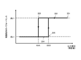
- FIG. 2 is a diagram showing the charge / discharge characteristics of the battery 112 when the device operation is performed by switching the operation mode according to the remaining capacity of the battery 112.
- FIG. 3 is a diagram illustrating a specific configuration example of a data transfer system 300 to which the technology disclosed in this specification is applied.
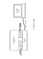
- FIG. 4 is a diagram schematically showing the internal configuration of the digital camera 310, the cradle 320, and the personal computer 330.
- FIG. 5A is a diagram showing power consumption in the digital camera 310 when short-distance high-speed wireless communication is performed with a duty of 100%.
- FIG. 5A is a diagram showing power consumption in the digital camera 310 when short-distance high-speed wireless communication is performed with a duty of 100%.
- FIG. 5B is a diagram showing power consumption in the digital camera 310 when short-distance high-speed wireless communication is performed with a duty of 10%.
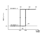
- FIG. 6 is a diagram showing charge / discharge characteristics of the battery 312 when the operation mode of the short-range communication control unit 313 is switched according to the remaining capacity of the battery 312 to perform device operation.
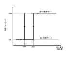
- FIG. 7A is a diagram showing the charge / discharge characteristics of the battery 312 when the operation mode of the short-range communication control unit 313 is switched according to the remaining capacity of the battery 312 (the amount of transfer data is large and the threshold value is set). If raised).
- FIG. 7B is a diagram showing the charge / discharge characteristics of the battery 312 when the operation mode of the short-range communication control unit 313 is switched according to the remaining capacity of the battery 312 (the transfer data is small and the threshold value is set). When lowered).
- FIG. 8 is a flowchart showing a processing procedure when the digital camera 310 performs short-distance high-speed wireless communication.
- FIG. 1 schematically shows a configuration of a data transfer system 100 to which the technology disclosed in this specification is applied.
- the illustrated data transfer system 100 includes an electronic device 110 and a power supply device 120 that supplies power to the electronic device 110 from the outside.
- the power feeding device 120 may obtain power feeding power from a commercial power source or may obtain power feeding from a USB host (not shown) such as a personal computer. Further, it is assumed that power is obtained from a USB host as a USB-connected cradle. When the power supply apparatus 120 obtains power supply from the USB host, the maximum current that can be supplied to the electronic device 110 depends on the connection destination of the USB port, and may flow up to 1.5 A or only 500 mA.
- the electronic device 110 is, for example, a digital camera, a mobile phone, or a portable music player, and the power supply device 120 is a cradle as described above, the electronic device 110 is connected to a USB host (such as a personal computer) via the cradle. It is assumed that communication (synchronization processing or the like) is performed with a device (not shown).
- a USB host such as a personal computer
- the electronic device 110 includes a processing unit 113 that executes device operations, a battery 112, and a charge / discharge control unit 111, as illustrated.
- the charge / discharge control unit 111 controls the supply of external power from the power supply device 120 to the processing unit 113, the charging of the battery 112, and the discharging of the battery 112.
- the charging / discharging control unit 111 basically supplies the external power from the power feeding device 120 with priority to the processing unit 113 and charges the battery 112 using the surplus power.
- the charge / discharge control unit 111 controls the discharge of the battery 112, that is, the power supply from the battery 112 to the processing unit 113 while monitoring the remaining capacity of the battery 112.
- the power supply to the processing unit 113 is insufficient with only the external power from the power supply device 120.
- the power feeding efficiency is as low as about 50%, so that it is assumed that the power necessary for device operation is insufficient with only the external power. Is done.
- the charging / discharging control unit 111 not only connects the power supply device 120 to the electronic device 110 but also external power from the power supply device 120 even when the power supply device 120 is connected to the electronic device 110.
- the power supply to the processing unit 113 is insufficient, the power supply from the battery 112 to the processing unit 113 is performed.
- the charge / discharge control unit 111 can calculate the remaining capacity by measuring the output voltage of the battery 112, for example, but can also calculate the remaining capacity from the integrated value of the charge / discharge current. In the following, for the sake of simplicity of explanation, the remaining capacity of the battery 112 is monitored from the output voltage.
- Device operations performed by the processing unit 113 include communication operations with external devices (including communication operations with a USB host via a cradle), shooting operations, and playback operations of captured images (provided that the electronic device 110 is a digital camera). Display operation (provided that the electronic device 110 includes a display panel). The device operation can be executed when the USB port connection destination can pass a current of 1.5 A, but the device operation may not be executed when only 500 mA can flow.
- the processing unit 113 can perform device operation in a plurality of operation modes with different power consumptions, and is configured to switch the operation mode based on the remaining capacity of the battery 112. That is, the processing unit 113 performs device operation in an operation mode with high performance but high performance when the remaining capacity of the battery 112 is high, but operates with low power consumption while suppressing performance when the remaining capacity of the battery 112 decreases. By shifting to the mode, the remaining capacity can be recovered by allowing the battery 112 to be charged even during operation of the device.
- the processing unit 113 operates in a first operation mode in which only the external power from the power supply apparatus 120 can be operated, and a second operation mode in which power exceeding the external power from the power supply apparatus 120 is used for device operation. It has.
- the processing unit 113 can operate by feeding power from the battery 112 in addition to external power from the feeding device 120.
- the power supply device 120 is a cradle and the connection destination of the USB port can pass a current of 1.5 A
- the device operation can be executed in the second operation mode by the power supplied from the cradle, but the connection destination of the USB port is only 500 mA.
- the device operation may not be executed in the second operation mode only with the power supplied from the cradle.
- the processing unit 113 reduces the power consumption by suppressing the performance of the device operation.
- the battery 112 can be charged with surplus power obtained by subtracting the amount consumed by the processing unit 113 from the external power from the power supply device 120.
- the processing unit 113 can improve the performance of the device operation, but consumes the capacity of the battery 112. In other words, the battery 112 cannot be charged in the second operation mode, and the processing unit 113 cannot continue the device operation in the second operation mode when the remaining capacity of the battery 112 is low.
- the first operation mode corresponds to a transfer operation with reduced performance.
- This operation mode corresponds to a transfer operation with high performance.
- the device operation performed by the processing unit 113 is a wireless communication operation in a wireless network or the like
- the first operation mode corresponds to a communication operation in which transmission power is suppressed
- the second operation mode increases transmission power. This corresponds to the communication operation performed.
- the electronic device 110 is a digital camera, only the reproduction of the captured image is permitted in the first operation mode, and the image capturing operation as well as the image reproduction is permitted in the second operation mode.
- the first operation mode corresponds to a display operation in which the luminance of the display panel is suppressed
- the second operation mode is an operation to display and output the display panel with high luminance.
- the first operation mode is equivalent to allowing the GPS function to be intermittently operated by allowing a decrease in position positioning performance.
- the operation mode corresponds to making the position measurement performance good by fully operating the GPS function.
- the processing unit 113 executes the device operation in the second operation mode when the remaining capacity of the battery 112 is sufficient. However, when the remaining capacity of the battery 112 decreases, the processing unit 113 shifts to the first operation mode and suppresses performance. The device operation continues, but at the same time, the battery 112 is charged to recover the remaining capacity.
- the electronic device 110 can efficiently charge the battery 112 while continuing the device operation even if the maximum current standard of the external power from the power supply device 120 is kept low. In addition, when the remaining capacity of the battery 112 is sufficient, the electronic device 110 can execute a device operation in which the power is insufficient with only the external power from the power supply device 120 by using the discharged power from the battery 112 as well. .
- FIG. 2 shows the charge / discharge characteristics of the battery 112 when the processing unit 113 switches the operation mode in accordance with the remaining capacity of the battery 112 to perform device operation. However, the remaining capacity is measured based on the output voltage of the battery 112.
- the processing unit 113 starts the device operation in the second operation mode (reference number 201).
- the performance of the processing unit 113 is high, but since it operates with power supplied from the battery 112 in addition to external power from the power supply device 120, the remaining capacity of the battery 112 gradually decreases, Along with this, the output voltage also decreases (reference number 202).
- the processing unit 113 Under the second operation mode, the battery 112 cannot be charged. Of course, the processing unit 113 cannot continue the device operation in the second operation mode when the remaining capacity of the battery 112 is small. Therefore, when the output voltage of the battery 112 falls below the first threshold AAA, the processing unit 113 switches from the second operation mode to the first operation mode (reference number 203).
- the processing unit 113 reduces the power consumption by suppressing the performance of the device operation. Since the battery 112 is charged with surplus power obtained by subtracting the amount consumed by the processing unit 113 from the external power from the power supply device 120, the remaining capacity of the battery 112 gradually increases, and the output is accordingly generated. The voltage also increases (reference number 204).
- the processing unit 113 returns to the second operation mode and performs the operation with the original high performance.
- the operation is performed (reference number 205). Further, as the processing unit 113 shifts to the second operation mode, the supply of the charging current of the battery 112 is also stopped.
- the first threshold AAA when the processing unit 113 shifts from the second operation mode to the first operation mode is the same as the first threshold AAA from the first operation mode to the second operation mode. It is smaller than the second threshold BBB at the time of transition (AAA ⁇ BBB).
- the reason why the first threshold AAA and the second threshold BBB are not made the same and has a hysteresis characteristic as shown in the figure is that the operation mode of the processing unit 113 is frequently switched due to the measurement error of the output voltage of the battery 112. This is to prevent the operation from becoming unstable.
- the first threshold AAA may be set to a lower value when it is desired to operate the processing unit 113 in the second operation mode for a longer period of time or when a lower remaining capacity of the battery 112 is allowed. Conversely, when the remaining capacity of the battery 112 is not desired to be too low, the first threshold AAA may be set to a higher value. Further, the second threshold BBB may be set to a higher value when it is desired to restore the battery 112 to a state close to full charge, and the second threshold BBB may be increased if the remaining capacity of the battery 112 is not strictly required. A low value may be set.
- FIG. 3 shows a specific configuration example of the data transfer system 300 to which the technology disclosed in this specification is applied.
- the illustrated data transfer system 300 includes a digital camera 310 corresponding to an electronic device, a personal computer 330 that manages image data captured by the digital camera 310, and a personal computer 330 as a USB host via a USB cable 331. It is comprised with the cradle 320 as a connected electric power feeder.
- the digital camera 310 is connected to the cradle 320 in a non-contact manner. Accordingly, the digital camera 310 installed on the cradle 320 can perform data transfer as a USB device via the USB cable 331 and perform synchronization processing with the personal computer 330. Further, the cradle 320 transmits power supplied via the VBUS terminal of the USB cable 331 to the digital camera 310 in a non-contact manner.
- non-contact communication using an electromagnetic induction method
- short-range high-speed wireless communication using a weak UWB method using a UWB (Ultra Wide Band) low band (4 GHz band).
- UWB Ultra Wide Band
- these communication means are used.
- non-contact communication for example, an RFID standard whose specifications are formulated by NFC (Near Field Communication) can be applied.
- NFC Near Field Communication
- Transfer Jet is used for the short-range high-speed wireless communication of the weak UWB system.
- html (as of November 7, 2011).
- power transmission from the cradle 320 to the digital camera 310 can be performed.
- Data transfer between the digital camera 310 and the cradle 320 (synchronization processing between the digital camera 310 and the personal computer 330 via the cradle 320) can be performed using short-distance high-speed wireless communication.
- the power that can be supplied from the cradle 320 to the digital camera 310 also decreases. For this reason, the external power supplied from the personal computer 330 via the cradle 320 is not sufficient on the digital camera 310 side. There are some device operations of the digital camera 310 where external power from the cradle 320 is not sufficient.
- FIG. 4 schematically shows the internal configuration of the digital camera 310, the cradle 320, and the personal computer 330.
- the illustration mainly focuses on the power supply to the digital camera 310 and the data transfer function between the digital camera 310 and the personal computer 330.
- the cradle 320 includes a USB interface 321, a non-contact communication control unit 322, and a near field communication control unit 323.
- the non-contact communication control unit 322 connects to the digital camera 310 side by using, for example, the NFC method using the electromagnetic induction action of the coil.
- the non-contact communication control unit 322 performs communication for authentication processing and transmits external power received from the USB power supply unit 332 of the personal computer 330 through the USB interface 321 to the digital camera 310.
- the short-range communication control unit 323 performs high-speed data transfer with the digital camera 310 by, for example, a weak UWB method. Data such as an image received by the short-range communication control unit 323 is transmitted from the USB interface 321 to the USB data unit 333 on the personal computer 330 side.
- the maximum current standard that can be passed from the USB power supply unit 332 to the VBUS terminal of the USB cable 331 is as low as 500 mA, and the power that can be supplied from the cradle 320 to the digital camera 310 is also low. Lower. For this reason, the external power supplied from the personal computer 330 via the cradle 320 is not sufficient on the digital camera 310 side.
- the digital camera 310 includes a non-contact communication control unit 314, a short-range communication control unit 313, a charge / discharge control unit 311, a battery 312, and a control unit 315. Note that, for the sake of simplification of the drawings, illustration of a photographing optical system and a processing block of a photographed image is omitted.
- the non-contact communication control unit 314 is connected to the cradle 320 by, for example, the NFC method using the electromagnetic induction action of the coil.
- the non-contact communication control unit 314 performs communication for authentication processing and receives external power from the cradle 320.
- the short-range communication control unit 313 performs short-range high-speed wireless communication with the cradle 320 by, for example, a weak UWB method.
- the charge / discharge control unit 311 controls the supply of external power from the cradle 320 to each unit 313 to 315, the charging of the battery 312, and the discharging of the battery 312 according to an instruction from the control unit 315.
- the external power from the cradle 320 is basically used in preference to power feeding to the units 313 to 315, and the surplus power is used for charging the battery 312.
- the control unit 315 controls the discharge of the battery 312, that is, the power supply from the battery 312 to each of the units 313 to 315 while monitoring the remaining capacity of the battery 312. For example, the control unit 315 can measure the output voltage of the battery 312 and obtain the remaining capacity.
- the short-range communication control unit 313 performs short-distance high-speed wireless communication by the weak UWB method exceeding a predetermined duty
- the communication operation is performed only with the external power supplied from the cradle 320 by non-contact communication. Therefore, the charge / discharge control unit 311 supplies power from the battery 312 to the short-range communication control unit 313 and the like.
- the short-range communication control unit 313 performs short-range high-speed wireless communication by the weak UWB method at a predetermined duty or less, the communication operation is sufficiently performed even with external power supplied from the cradle 320 by non-contact communication. Can do. In this case, the charge / discharge control unit 311 uses surplus power of the external power for charging the battery 312.
- the digital camera 310 defines a plurality of operation modes with different duty ratios for short-distance high-speed wireless communication in the short-range communication control unit 313. Since the power consumption of the entire device varies depending on the duty ratio, switching the operation mode based on the remaining capacity of the battery 312 makes it possible to obtain surplus power during short-distance high-speed wireless communication and to charge the battery 312. Yes.
- a first operation mode in which the short-range communication control unit 313 performs a communication operation with a duty of 10% so that short-distance high-speed wireless communication can be sufficiently performed even with external power supplied from the cradle 320 by non-contact communication.
- a second operation mode is defined in which the short-range communication control unit 313 performs a communication operation with a duty of 100% by feeding from the battery 112.
- the power consumption is reduced by suppressing the performance of the communication operation in the short-range communication control unit 313.
- the charge / discharge control unit 311 can charge the battery 312 with surplus power obtained by subtracting the amount consumed by the short-range communication control unit 313 from the external power supplied from the cradle 320 by non-contact communication.
- FIG. 5A shows the power consumption in the digital camera 310 when short-distance high-speed wireless communication is performed with a duty of 100%.
- the duty 100% means that data is actually transferred in all the sections in which short-distance high-speed wireless communication is possible.
- discharge power from the battery 312 is supplied to the units 313 to 315.
- the performance of the communication operation in the short-range communication control unit 313 can be improved, but the capacity of the battery 312 is consumed.
- the battery 312 cannot be charged in the second operation mode, and the processing unit 113 cannot continue the device operation in the second operation mode when the remaining capacity of the battery 312 is low. .
- FIG. 5B shows power consumption in the digital camera 310 when short-distance high-speed wireless communication is performed with a duty of 10%.
- the duty of 10% means that only 10% of the time during which short-distance high-speed wireless communication is possible is actually transferred, and in the remaining 90%, data is not sent and the sleep state (consumption This means that the electric power is low), and less electric power is consumed when viewed as a steady electronic consideration.
- the battery 312 is charged with external power supplied from the cradle 320 by non-contact communication in a section where the short-distance high-speed wireless communication operation is stopped.
- the control unit 315 operates the short-range communication control unit 313 in the second operation mode when the remaining capacity of the battery 312 is sufficient, but when the remaining capacity of the battery 312 becomes low, the control unit 315 causes the short-range communication control unit 313 to operate.
- the operation mode is switched to continue the short-distance high-speed wireless communication operation while suppressing the performance, but at the same time, the battery 312 is charged to recover the remaining capacity.
- the digital camera 310 can efficiently charge the battery 312 while continuing the short-distance high-speed wireless communication operation even if the maximum current standard of the external power from the cradle 320 is kept low. Further, when the remaining capacity of the battery 312 is sufficient, the digital camera 310 executes a short-distance high-speed wireless communication operation in which the power is not sufficient only from the external power from the cradle 320 by using the discharge power from the battery 112 as well. be able to.
- FIG. 6 shows the charging / discharging characteristics of the battery 312 when the operation mode of the short-range communication control unit 313 is switched according to the remaining capacity of the battery 312 to perform device operation. However, the remaining capacity is measured based on the output voltage of the battery 312.
- the short-range communication control unit 313 starts communication operation with a high duty ratio in the second operation mode (reference number 601).
- the performance of short-distance high-speed wireless communication is high, but the remaining capacity of the battery 312 gradually decreases because the power is supplied from the battery 312 in addition to the external power from the cradle 320. Accordingly, the output voltage also decreases (reference number 602).
- control unit 315 switches short-range communication control unit 313 from the second operation mode to the first operation mode (reference number 603).
- the control unit 315 returns the short-range communication control unit 313 to the second operation mode.
- the communication operation is performed with the original high performance (reference number 605).
- the short-range communication control unit 313 shifts to the second operation mode, the supply of the charging current of the battery 312 is also stopped.
- the first threshold AAA when the short-range communication control unit 313 shifts from the second operation mode to the first operation mode is the short-range communication control unit 313. It is smaller than the second threshold value BBB when shifting from the first operation mode to the second operation mode (AAA ⁇ BBB).
- the reason why the first threshold AAA and the second threshold BBB are not made the same and has a hysteresis characteristic as shown in the figure is that the operation mode of the short-range communication control unit 313 is switched due to the measurement error of the output voltage of the battery 312. This is to prevent the occurrence of frequent occurrences and unstable operation.
- the settings of the first threshold AAA and the second threshold BBB may be changed according to the amount of data transferred by short-distance high-speed wireless communication. For example, when the amount of transfer data is large, as shown in FIG. 7A, the first threshold AAA and the second threshold BBB are raised to reduce the area for short-distance high-speed wireless communication with a duty of 100%. Thus, the remaining capacity of the battery 312 is always kept high while enormous data transfer is performed for a long time. Conversely, when the amount of transferred data is small, as shown in FIG. 7B, the first threshold AAA and the second threshold BBB are lowered to increase the area for performing short-distance high-speed wireless communication with a duty of 100%. As a result, the data transfer is completed in a short period of time, and charging of the battery 312 can be started immediately.
- FIG. 8 shows a processing procedure when the digital camera 310 performs short-distance high-speed wireless communication in the form of a flowchart.
- This processing procedure can be realized, for example, in a form in which a predetermined program code is executed in the control unit 315.
- the charge / discharge control unit 311 detects the power supply power, thereby detecting the cradle 320 (Yes in step S801).
- control unit 315 checks the remaining capacity from the output voltage of the battery 312 (step S802).
- control unit 315 sets the short-range communication control unit 313 to the second operation mode (Ste S804).
- the near field communication control unit 313 executes near field high speed wireless communication with a duty of 100% under the second operation mode. Although the transfer rate between the digital camera 310 and the cradle 320 increases, the power consumption increases, and this is supplemented by the power supply from the battery 312, so the remaining capacity of the battery 312 decreases and the output voltage decreases. Thereafter, the process returns to step S802, and the remaining capacity of the battery 312 is checked again.
- the control unit 315 sets the short-range communication control unit 313 to the first operation mode (Step S803). S805).
- the near field communication control unit 313 performs near field high speed wireless communication with a duty of 10% under the first operation mode. Although the transfer rate between the digital camera 310 and the cradle 320 is reduced, the power consumption is reduced, so that the battery 312 can be charged using surplus power out of the external power from the cradle 320. As a result, the remaining capacity of the battery 312 increases and the output voltage increases.
- control unit 315 sets the short-range communication control unit 313 to the second operation mode. (Step S804).
- the near field communication control unit 313 executes near field high speed wireless communication with a duty of 100% under the second operation mode. Although the transfer rate between the digital camera 310 and the cradle 320 increases, the power consumption increases, and this is supplemented by the power supply from the battery 312, so the remaining capacity of the battery 312 decreases and the output voltage decreases. Thereafter, the process returns to step S802, and the remaining capacity of the battery 312 is checked again (same as above).
- the control unit 315 keeps the short-range communication control unit 313 in the second operation mode setting. (Step S805). Accordingly, the near field communication control unit 313 continues to perform near field high speed wireless communication with a duty of 10%. Although the transfer rate between the digital camera 310 and the cradle 320 remains low, charging of the battery 312 continues using surplus power out of the external power from the cradle 320, so that the remaining capacity of the battery 312 further increases and the output is increased. The voltage increases.
- the digital camera 310 performs the data transfer operation according to the processing procedure shown in FIG. 8, so that the cradle 320 can be connected by short-distance high-speed wireless communication while maintaining the battery charging efficiency even when the remaining battery capacity is reduced. And data transfer can be performed.
- the digital camera 310 can execute short-distance high-speed wireless communication with a high duty that is not sufficient with only the external power supplied from the cradle 320 by using the discharge power from the battery.
- a battery a processing unit that performs device operation
- a charge / discharge control unit that controls power supply to the processing unit, charging of the battery, and power supply from the battery to the processing unit using external power
- the processing unit has a first operation mode in which device operation is performed below the external power, and a second operation mode in which device operation is performed using power exceeding the external power
- An electronic device that performs device operation by switching the processing unit to the first operation mode or the second operation mode in accordance with a remaining battery capacity.
- the charge / discharge control unit preferentially supplies the external power to the processing unit and charges the battery using surplus power.
- the charge / discharge control unit charges the battery using surplus power of the external power consumed by the processing unit.
- the electronic device according to (1) which is performed.
- the charge / discharge control unit supplies power exceeding the external power from the battery to the processing unit.
- the electronic device as described in 1).
- the processing unit performs device operation in the second operation mode, and when the remaining capacity of the battery is small, the processing unit operates in the first operation mode.
- the electronic device according to (1) wherein the electronic device executes an operation.
- the processing unit shifts to the first operation mode and surplus power of the external power
- the battery is charged using the first and the processing unit is performing device operation in the first operation mode, and the remaining capacity of the battery becomes equal to or higher than a second threshold value that is higher than the first threshold value.
- the electronic device according to (1) wherein the electronic device shifts to the second operation mode.
- the electronic device is a digital camera or other portable device, and the external power is supplied from a cradle that is USB-connected to a USB host.
- a charge control method comprising: a first device operation step of executing a device operation in a first operation mode that consumes power equal to or less than the external power in the electronic device.
- the charge control method further comprising: (12) An electronic device and a power supply device that supplies power to the electronic device are provided, the electronic device including a battery and a first operation mode in which the device operates with less than external power supplied from the power supply device.
- a charging system that switches to and executes device operations.
- An electronic device and a cradle for installing the electronic device and connected by USB are provided, and the cradle transmits electric power obtained via a USB cable to the electronic device by non-contact communication.
- a short-distance high-speed wireless communication operation by switching the processing unit to the first operation mode or the second operation mode according to the remaining capacity of the battery. Transfer system.
- the digital camera has been described mainly with respect to an embodiment applied to a system in which a digital camera performs contactless communication using a USB-connected cradle and charges a battery in the digital camera.
- the other various electronic devices can be applied when charging at the same time as the device operation.
- the technology disclosed in this specification can be similarly applied to various electronic devices using a battery such as an emergency power source.
- DESCRIPTION OF SYMBOLS 100 ... Data transfer system 110 ... Electronic device 111 ... Charge / discharge control part 112 ... Battery 113 ... Processing part 120 ... Power supply apparatus 300 ... Data transfer system 310 ... Digital camera 311 ... Charge / discharge control part 312 ... Battery 313 ... Near field communication control 314: Non-contact communication control unit 315 ... Control unit 320 ... Cradle 321 ... USB interface 322 ... Non-contact communication control unit 323 ... Short-range communication control unit 330 ... Personal computer 331 ... USB cable 332 ... USB power supply unit 333 ... USB Data section
Landscapes
- Engineering & Computer Science (AREA)
- Power Engineering (AREA)
- Computer Networks & Wireless Communication (AREA)
- Signal Processing (AREA)
- Theoretical Computer Science (AREA)
- General Chemical & Material Sciences (AREA)
- Manufacturing & Machinery (AREA)
- Chemical & Material Sciences (AREA)
- Chemical Kinetics & Catalysis (AREA)
- Electrochemistry (AREA)
- General Physics & Mathematics (AREA)
- General Engineering & Computer Science (AREA)
- Physics & Mathematics (AREA)
- Charge And Discharge Circuits For Batteries Or The Like (AREA)
- Secondary Cells (AREA)
- Near-Field Transmission Systems (AREA)
Priority Applications (3)
| Application Number | Priority Date | Filing Date | Title |
|---|---|---|---|
| US14/348,934 US10122197B2 (en) | 2011-11-18 | 2012-09-06 | Controlling a display based on different modes of operation |
| CN201280055040.5A CN103918157B (zh) | 2011-11-18 | 2012-09-06 | 电子设备、充电控制方法、充电系统和数据传输系统 |
| EP12850579.9A EP2782211A4 (en) | 2011-11-18 | 2012-09-06 | ELECTRONIC DEVICE, CHARGING CONTROL METHOD, CHARGING SYSTEM AND DATA TRANSMISSION SYSTEM |
Applications Claiming Priority (2)
| Application Number | Priority Date | Filing Date | Title |
|---|---|---|---|
| JP2011-252829 | 2011-11-18 | ||
| JP2011252829A JP5790434B2 (ja) | 2011-11-18 | 2011-11-18 | 電子機器、充電制御方法、充電システム、並びにデータ転送システム |
Publications (1)
| Publication Number | Publication Date |
|---|---|
| WO2013073267A1 true WO2013073267A1 (ja) | 2013-05-23 |
Family
ID=48429341
Family Applications (1)
| Application Number | Title | Priority Date | Filing Date |
|---|---|---|---|
| PCT/JP2012/072808 Ceased WO2013073267A1 (ja) | 2011-11-18 | 2012-09-06 | 電子機器、充電制御方法、充電システム、並びにデータ転送システム |
Country Status (5)
| Country | Link |
|---|---|
| US (1) | US10122197B2 (https=) |
| EP (1) | EP2782211A4 (https=) |
| JP (1) | JP5790434B2 (https=) |
| CN (1) | CN103918157B (https=) |
| WO (1) | WO2013073267A1 (https=) |
Cited By (1)
| Publication number | Priority date | Publication date | Assignee | Title |
|---|---|---|---|---|
| EP2882067A3 (en) * | 2013-11-04 | 2015-07-22 | Samsung Electronics Co., Ltd | Battery-charging apparatus and method of electronic device |
Families Citing this family (219)
| Publication number | Priority date | Publication date | Assignee | Title |
|---|---|---|---|---|
| US10090662B2 (en) * | 2011-01-31 | 2018-10-02 | Electronic Systems Protection, Inc. | Power monitoring and management with remote access |
| US9037877B2 (en) * | 2012-01-20 | 2015-05-19 | Dell Products L.P. | System and method for operating a plurality of components according to first or second operating characteristics in response to a detected first or second power input characteristic associated with a first or second power input respectively |
| US9490648B2 (en) * | 2012-04-30 | 2016-11-08 | Hewlett-Packard Development Company, L.P. | Alternating current direct current adapter with wireless charging |
| US9825674B1 (en) | 2014-05-23 | 2017-11-21 | Energous Corporation | Enhanced transmitter that selects configurations of antenna elements for performing wireless power transmission and receiving functions |
| US10075008B1 (en) | 2014-07-14 | 2018-09-11 | Energous Corporation | Systems and methods for manually adjusting when receiving electronic devices are scheduled to receive wirelessly delivered power from a wireless power transmitter in a wireless power network |
| US9906065B2 (en) | 2012-07-06 | 2018-02-27 | Energous Corporation | Systems and methods of transmitting power transmission waves based on signals received at first and second subsets of a transmitter's antenna array |
| US10205239B1 (en) | 2014-05-07 | 2019-02-12 | Energous Corporation | Compact PIFA antenna |
| US10038337B1 (en) | 2013-09-16 | 2018-07-31 | Energous Corporation | Wireless power supply for rescue devices |
| US10128699B2 (en) | 2014-07-14 | 2018-11-13 | Energous Corporation | Systems and methods of providing wireless power using receiver device sensor inputs |
| US9991741B1 (en) | 2014-07-14 | 2018-06-05 | Energous Corporation | System for tracking and reporting status and usage information in a wireless power management system |
| US9876394B1 (en) | 2014-05-07 | 2018-01-23 | Energous Corporation | Boost-charger-boost system for enhanced power delivery |
| US10199835B2 (en) | 2015-12-29 | 2019-02-05 | Energous Corporation | Radar motion detection using stepped frequency in wireless power transmission system |
| US9859756B2 (en) | 2012-07-06 | 2018-01-02 | Energous Corporation | Transmittersand methods for adjusting wireless power transmission based on information from receivers |
| US11502551B2 (en) | 2012-07-06 | 2022-11-15 | Energous Corporation | Wirelessly charging multiple wireless-power receivers using different subsets of an antenna array to focus energy at different locations |
| US10206185B2 (en) | 2013-05-10 | 2019-02-12 | Energous Corporation | System and methods for wireless power transmission to an electronic device in accordance with user-defined restrictions |
| US9871398B1 (en) | 2013-07-01 | 2018-01-16 | Energous Corporation | Hybrid charging method for wireless power transmission based on pocket-forming |
| US10148097B1 (en) | 2013-11-08 | 2018-12-04 | Energous Corporation | Systems and methods for using a predetermined number of communication channels of a wireless power transmitter to communicate with different wireless power receivers |
| US9876379B1 (en) | 2013-07-11 | 2018-01-23 | Energous Corporation | Wireless charging and powering of electronic devices in a vehicle |
| US10193396B1 (en) | 2014-05-07 | 2019-01-29 | Energous Corporation | Cluster management of transmitters in a wireless power transmission system |
| US9923386B1 (en) | 2012-07-06 | 2018-03-20 | Energous Corporation | Systems and methods for wireless power transmission by modifying a number of antenna elements used to transmit power waves to a receiver |
| US9859757B1 (en) | 2013-07-25 | 2018-01-02 | Energous Corporation | Antenna tile arrangements in electronic device enclosures |
| US9893555B1 (en) | 2013-10-10 | 2018-02-13 | Energous Corporation | Wireless charging of tools using a toolbox transmitter |
| US9438045B1 (en) | 2013-05-10 | 2016-09-06 | Energous Corporation | Methods and systems for maximum power point transfer in receivers |
| US10211680B2 (en) | 2013-07-19 | 2019-02-19 | Energous Corporation | Method for 3 dimensional pocket-forming |
| US10063105B2 (en) | 2013-07-11 | 2018-08-28 | Energous Corporation | Proximity transmitters for wireless power charging systems |
| US9806564B2 (en) | 2014-05-07 | 2017-10-31 | Energous Corporation | Integrated rectifier and boost converter for wireless power transmission |
| US20150326070A1 (en) | 2014-05-07 | 2015-11-12 | Energous Corporation | Methods and Systems for Maximum Power Point Transfer in Receivers |
| US10312715B2 (en) | 2015-09-16 | 2019-06-04 | Energous Corporation | Systems and methods for wireless power charging |
| US9941747B2 (en) | 2014-07-14 | 2018-04-10 | Energous Corporation | System and method for manually selecting and deselecting devices to charge in a wireless power network |
| US9793758B2 (en) | 2014-05-23 | 2017-10-17 | Energous Corporation | Enhanced transmitter using frequency control for wireless power transmission |
| US10243414B1 (en) | 2014-05-07 | 2019-03-26 | Energous Corporation | Wearable device with wireless power and payload receiver |
| US10270261B2 (en) | 2015-09-16 | 2019-04-23 | Energous Corporation | Systems and methods of object detection in wireless power charging systems |
| US9812890B1 (en) | 2013-07-11 | 2017-11-07 | Energous Corporation | Portable wireless charging pad |
| US9912199B2 (en) | 2012-07-06 | 2018-03-06 | Energous Corporation | Receivers for wireless power transmission |
| US9948135B2 (en) | 2015-09-22 | 2018-04-17 | Energous Corporation | Systems and methods for identifying sensitive objects in a wireless charging transmission field |
| US10211682B2 (en) | 2014-05-07 | 2019-02-19 | Energous Corporation | Systems and methods for controlling operation of a transmitter of a wireless power network based on user instructions received from an authenticated computing device powered or charged by a receiver of the wireless power network |
| US10103582B2 (en) | 2012-07-06 | 2018-10-16 | Energous Corporation | Transmitters for wireless power transmission |
| US9867062B1 (en) | 2014-07-21 | 2018-01-09 | Energous Corporation | System and methods for using a remote server to authorize a receiving device that has requested wireless power and to determine whether another receiving device should request wireless power in a wireless power transmission system |
| US10381880B2 (en) | 2014-07-21 | 2019-08-13 | Energous Corporation | Integrated antenna structure arrays for wireless power transmission |
| US9941707B1 (en) | 2013-07-19 | 2018-04-10 | Energous Corporation | Home base station for multiple room coverage with multiple transmitters |
| US10063064B1 (en) | 2014-05-23 | 2018-08-28 | Energous Corporation | System and method for generating a power receiver identifier in a wireless power network |
| US10224982B1 (en) | 2013-07-11 | 2019-03-05 | Energous Corporation | Wireless power transmitters for transmitting wireless power and tracking whether wireless power receivers are within authorized locations |
| US10008889B2 (en) | 2014-08-21 | 2018-06-26 | Energous Corporation | Method for automatically testing the operational status of a wireless power receiver in a wireless power transmission system |
| US20140008993A1 (en) | 2012-07-06 | 2014-01-09 | DvineWave Inc. | Methodology for pocket-forming |
| US10128693B2 (en) | 2014-07-14 | 2018-11-13 | Energous Corporation | System and method for providing health safety in a wireless power transmission system |
| US10230266B1 (en) | 2014-02-06 | 2019-03-12 | Energous Corporation | Wireless power receivers that communicate status data indicating wireless power transmission effectiveness with a transmitter using a built-in communications component of a mobile device, and methods of use thereof |
| US9893554B2 (en) | 2014-07-14 | 2018-02-13 | Energous Corporation | System and method for providing health safety in a wireless power transmission system |
| US10992187B2 (en) | 2012-07-06 | 2021-04-27 | Energous Corporation | System and methods of using electromagnetic waves to wirelessly deliver power to electronic devices |
| US9899861B1 (en) | 2013-10-10 | 2018-02-20 | Energous Corporation | Wireless charging methods and systems for game controllers, based on pocket-forming |
| US10263432B1 (en) | 2013-06-25 | 2019-04-16 | Energous Corporation | Multi-mode transmitter with an antenna array for delivering wireless power and providing Wi-Fi access |
| US10439448B2 (en) | 2014-08-21 | 2019-10-08 | Energous Corporation | Systems and methods for automatically testing the communication between wireless power transmitter and wireless power receiver |
| US9941754B2 (en) | 2012-07-06 | 2018-04-10 | Energous Corporation | Wireless power transmission with selective range |
| US9887739B2 (en) | 2012-07-06 | 2018-02-06 | Energous Corporation | Systems and methods for wireless power transmission by comparing voltage levels associated with power waves transmitted by antennas of a plurality of antennas of a transmitter to determine appropriate phase adjustments for the power waves |
| US9882430B1 (en) | 2014-05-07 | 2018-01-30 | Energous Corporation | Cluster management of transmitters in a wireless power transmission system |
| US9847677B1 (en) | 2013-10-10 | 2017-12-19 | Energous Corporation | Wireless charging and powering of healthcare gadgets and sensors |
| US10291055B1 (en) | 2014-12-29 | 2019-05-14 | Energous Corporation | Systems and methods for controlling far-field wireless power transmission based on battery power levels of a receiving device |
| US9887584B1 (en) | 2014-08-21 | 2018-02-06 | Energous Corporation | Systems and methods for a configuration web service to provide configuration of a wireless power transmitter within a wireless power transmission system |
| US10256657B2 (en) | 2015-12-24 | 2019-04-09 | Energous Corporation | Antenna having coaxial structure for near field wireless power charging |
| US9966765B1 (en) | 2013-06-25 | 2018-05-08 | Energous Corporation | Multi-mode transmitter |
| US10090699B1 (en) | 2013-11-01 | 2018-10-02 | Energous Corporation | Wireless powered house |
| US9124125B2 (en) | 2013-05-10 | 2015-09-01 | Energous Corporation | Wireless power transmission with selective range |
| US9847679B2 (en) | 2014-05-07 | 2017-12-19 | Energous Corporation | System and method for controlling communication between wireless power transmitter managers |
| US10291066B1 (en) | 2014-05-07 | 2019-05-14 | Energous Corporation | Power transmission control systems and methods |
| US10965164B2 (en) | 2012-07-06 | 2021-03-30 | Energous Corporation | Systems and methods of wirelessly delivering power to a receiver device |
| US9252628B2 (en) | 2013-05-10 | 2016-02-02 | Energous Corporation | Laptop computer as a transmitter for wireless charging |
| US9973021B2 (en) | 2012-07-06 | 2018-05-15 | Energous Corporation | Receivers for wireless power transmission |
| US10223717B1 (en) | 2014-05-23 | 2019-03-05 | Energous Corporation | Systems and methods for payment-based authorization of wireless power transmission service |
| US9876648B2 (en) | 2014-08-21 | 2018-01-23 | Energous Corporation | System and method to control a wireless power transmission system by configuration of wireless power transmission control parameters |
| US9853458B1 (en) | 2014-05-07 | 2017-12-26 | Energous Corporation | Systems and methods for device and power receiver pairing |
| US10141791B2 (en) | 2014-05-07 | 2018-11-27 | Energous Corporation | Systems and methods for controlling communications during wireless transmission of power using application programming interfaces |
| US9838083B2 (en) | 2014-07-21 | 2017-12-05 | Energous Corporation | Systems and methods for communication with remote management systems |
| US9900057B2 (en) | 2012-07-06 | 2018-02-20 | Energous Corporation | Systems and methods for assigning groups of antenas of a wireless power transmitter to different wireless power receivers, and determining effective phases to use for wirelessly transmitting power using the assigned groups of antennas |
| US9368020B1 (en) | 2013-05-10 | 2016-06-14 | Energous Corporation | Off-premises alert system and method for wireless power receivers in a wireless power network |
| US10063106B2 (en) | 2014-05-23 | 2018-08-28 | Energous Corporation | System and method for a self-system analysis in a wireless power transmission network |
| US10050462B1 (en) | 2013-08-06 | 2018-08-14 | Energous Corporation | Social power sharing for mobile devices based on pocket-forming |
| US9882427B2 (en) | 2013-05-10 | 2018-01-30 | Energous Corporation | Wireless power delivery using a base station to control operations of a plurality of wireless power transmitters |
| US9843213B2 (en) | 2013-08-06 | 2017-12-12 | Energous Corporation | Social power sharing for mobile devices based on pocket-forming |
| US9853692B1 (en) | 2014-05-23 | 2017-12-26 | Energous Corporation | Systems and methods for wireless power transmission |
| US9954374B1 (en) | 2014-05-23 | 2018-04-24 | Energous Corporation | System and method for self-system analysis for detecting a fault in a wireless power transmission Network |
| US10992185B2 (en) | 2012-07-06 | 2021-04-27 | Energous Corporation | Systems and methods of using electromagnetic waves to wirelessly deliver power to game controllers |
| US10186913B2 (en) | 2012-07-06 | 2019-01-22 | Energous Corporation | System and methods for pocket-forming based on constructive and destructive interferences to power one or more wireless power receivers using a wireless power transmitter including a plurality of antennas |
| US10124754B1 (en) | 2013-07-19 | 2018-11-13 | Energous Corporation | Wireless charging and powering of electronic sensors in a vehicle |
| US9939864B1 (en) | 2014-08-21 | 2018-04-10 | Energous Corporation | System and method to control a wireless power transmission system by configuration of wireless power transmission control parameters |
| US10224758B2 (en) | 2013-05-10 | 2019-03-05 | Energous Corporation | Wireless powering of electronic devices with selective delivery range |
| US9859797B1 (en) | 2014-05-07 | 2018-01-02 | Energous Corporation | Synchronous rectifier design for wireless power receiver |
| US12057715B2 (en) | 2012-07-06 | 2024-08-06 | Energous Corporation | Systems and methods of wirelessly delivering power to a wireless-power receiver device in response to a change of orientation of the wireless-power receiver device |
| US9143000B2 (en) | 2012-07-06 | 2015-09-22 | Energous Corporation | Portable wireless charging pad |
| US9891669B2 (en) | 2014-08-21 | 2018-02-13 | Energous Corporation | Systems and methods for a configuration web service to provide configuration of a wireless power transmitter within a wireless power transmission system |
| US9893768B2 (en) | 2012-07-06 | 2018-02-13 | Energous Corporation | Methodology for multiple pocket-forming |
| US10199849B1 (en) | 2014-08-21 | 2019-02-05 | Energous Corporation | Method for automatically testing the operational status of a wireless power receiver in a wireless power transmission system |
| US10211674B1 (en) | 2013-06-12 | 2019-02-19 | Energous Corporation | Wireless charging using selected reflectors |
| US10141768B2 (en) | 2013-06-03 | 2018-11-27 | Energous Corporation | Systems and methods for maximizing wireless power transfer efficiency by instructing a user to change a receiver device's position |
| US9843201B1 (en) | 2012-07-06 | 2017-12-12 | Energous Corporation | Wireless power transmitter that selects antenna sets for transmitting wireless power to a receiver based on location of the receiver, and methods of use thereof |
| US10090886B1 (en) | 2014-07-14 | 2018-10-02 | Energous Corporation | System and method for enabling automatic charging schedules in a wireless power network to one or more devices |
| US9787103B1 (en) | 2013-08-06 | 2017-10-10 | Energous Corporation | Systems and methods for wirelessly delivering power to electronic devices that are unable to communicate with a transmitter |
| US9899873B2 (en) | 2014-05-23 | 2018-02-20 | Energous Corporation | System and method for generating a power receiver identifier in a wireless power network |
| US10218227B2 (en) | 2014-05-07 | 2019-02-26 | Energous Corporation | Compact PIFA antenna |
| US9831718B2 (en) | 2013-07-25 | 2017-11-28 | Energous Corporation | TV with integrated wireless power transmitter |
| US9824815B2 (en) | 2013-05-10 | 2017-11-21 | Energous Corporation | Wireless charging and powering of healthcare gadgets and sensors |
| US9866279B2 (en) | 2013-05-10 | 2018-01-09 | Energous Corporation | Systems and methods for selecting which power transmitter should deliver wireless power to a receiving device in a wireless power delivery network |
| US9537357B2 (en) | 2013-05-10 | 2017-01-03 | Energous Corporation | Wireless sound charging methods and systems for game controllers, based on pocket-forming |
| US9538382B2 (en) | 2013-05-10 | 2017-01-03 | Energous Corporation | System and method for smart registration of wireless power receivers in a wireless power network |
| US9819230B2 (en) | 2014-05-07 | 2017-11-14 | Energous Corporation | Enhanced receiver for wireless power transmission |
| US9419443B2 (en) | 2013-05-10 | 2016-08-16 | Energous Corporation | Transducer sound arrangement for pocket-forming |
| US10103552B1 (en) | 2013-06-03 | 2018-10-16 | Energous Corporation | Protocols for authenticated wireless power transmission |
| US10003211B1 (en) | 2013-06-17 | 2018-06-19 | Energous Corporation | Battery life of portable electronic devices |
| US10021523B2 (en) * | 2013-07-11 | 2018-07-10 | Energous Corporation | Proximity transmitters for wireless power charging systems |
| US9979440B1 (en) | 2013-07-25 | 2018-05-22 | Energous Corporation | Antenna tile arrangements configured to operate as one functional unit |
| JP6230324B2 (ja) * | 2013-08-05 | 2017-11-15 | キヤノン株式会社 | 受電装置、受電装置の制御方法及びプログラム |
| JP6052804B2 (ja) * | 2013-08-27 | 2016-12-27 | オムロンオートモーティブエレクトロニクス株式会社 | 携帯端末、通報制御方法、及び、通報システム |
| US10075017B2 (en) | 2014-02-06 | 2018-09-11 | Energous Corporation | External or internal wireless power receiver with spaced-apart antenna elements for charging or powering mobile devices using wirelessly delivered power |
| US9935482B1 (en) | 2014-02-06 | 2018-04-03 | Energous Corporation | Wireless power transmitters that transmit at determined times based on power availability and consumption at a receiving mobile device |
| US10158257B2 (en) | 2014-05-01 | 2018-12-18 | Energous Corporation | System and methods for using sound waves to wirelessly deliver power to electronic devices |
| US9966784B2 (en) | 2014-06-03 | 2018-05-08 | Energous Corporation | Systems and methods for extending battery life of portable electronic devices charged by sound |
| US10153653B1 (en) | 2014-05-07 | 2018-12-11 | Energous Corporation | Systems and methods for using application programming interfaces to control communications between a transmitter and a receiver |
| US10170917B1 (en) | 2014-05-07 | 2019-01-01 | Energous Corporation | Systems and methods for managing and controlling a wireless power network by establishing time intervals during which receivers communicate with a transmitter |
| US9800172B1 (en) | 2014-05-07 | 2017-10-24 | Energous Corporation | Integrated rectifier and boost converter for boosting voltage received from wireless power transmission waves |
| US10153645B1 (en) | 2014-05-07 | 2018-12-11 | Energous Corporation | Systems and methods for designating a master power transmitter in a cluster of wireless power transmitters |
| US9973008B1 (en) | 2014-05-07 | 2018-05-15 | Energous Corporation | Wireless power receiver with boost converters directly coupled to a storage element |
| US9876536B1 (en) | 2014-05-23 | 2018-01-23 | Energous Corporation | Systems and methods for assigning groups of antennas to transmit wireless power to different wireless power receivers |
| US10075001B2 (en) | 2014-06-03 | 2018-09-11 | Traxxas, LP | Battery connection method and apparatus |
| US10431992B2 (en) | 2014-06-03 | 2019-10-01 | Traxxas Lp | Battery charger with user interface |
| US10396568B2 (en) | 2014-06-03 | 2019-08-27 | Traxxas Lp | Battery charger with user interface |
| US9871301B2 (en) | 2014-07-21 | 2018-01-16 | Energous Corporation | Integrated miniature PIFA with artificial magnetic conductor metamaterials |
| US10068703B1 (en) | 2014-07-21 | 2018-09-04 | Energous Corporation | Integrated miniature PIFA with artificial magnetic conductor metamaterials |
| US10116143B1 (en) | 2014-07-21 | 2018-10-30 | Energous Corporation | Integrated antenna arrays for wireless power transmission |
| US9917477B1 (en) | 2014-08-21 | 2018-03-13 | Energous Corporation | Systems and methods for automatically testing the communication between power transmitter and wireless receiver |
| US9965009B1 (en) | 2014-08-21 | 2018-05-08 | Energous Corporation | Systems and methods for assigning a power receiver to individual power transmitters based on location of the power receiver |
| KR102336856B1 (ko) * | 2014-11-13 | 2021-12-08 | 삼성전자 주식회사 | 전자 장치 및 그의 배터리 충방전 제어 방법 |
| KR102429819B1 (ko) * | 2014-11-27 | 2022-08-08 | 한국전자통신연구원 | 무선 전력 수신 장치 및 그의 전력 제어 방법, 그리고 무선 전력 시스템 |
| JP6525576B2 (ja) * | 2014-12-17 | 2019-06-05 | キヤノン株式会社 | 制御装置、制御システム、制御方法、医用画像撮影装置、医用画像撮影システム、撮影制御方法およびプログラム |
| US20160181850A1 (en) * | 2014-12-22 | 2016-06-23 | Microsoft Corporation | Wireless charging apparatus |
| US10122415B2 (en) | 2014-12-27 | 2018-11-06 | Energous Corporation | Systems and methods for assigning a set of antennas of a wireless power transmitter to a wireless power receiver based on a location of the wireless power receiver |
| US9893535B2 (en) | 2015-02-13 | 2018-02-13 | Energous Corporation | Systems and methods for determining optimal charging positions to maximize efficiency of power received from wirelessly delivered sound wave energy |
| JP6544977B2 (ja) * | 2015-04-13 | 2019-07-17 | キヤノン株式会社 | 情報処理装置、制御方法及びプログラム |
| KR102295686B1 (ko) * | 2015-04-15 | 2021-08-31 | 삼성전자주식회사 | 외부 전자 장치와 하이브리드 통신을 수행하는 전자 장치 및 방법 |
| CN106208172B (zh) * | 2015-04-30 | 2020-06-16 | 微软技术许可有限责任公司 | 移动客户端设备无线充电、通信及认证技术 |
| US10523033B2 (en) | 2015-09-15 | 2019-12-31 | Energous Corporation | Receiver devices configured to determine location within a transmission field |
| US9906275B2 (en) | 2015-09-15 | 2018-02-27 | Energous Corporation | Identifying receivers in a wireless charging transmission field |
| US12283828B2 (en) | 2015-09-15 | 2025-04-22 | Energous Corporation | Receiver devices configured to determine location within a transmission field |
| US10199850B2 (en) | 2015-09-16 | 2019-02-05 | Energous Corporation | Systems and methods for wirelessly transmitting power from a transmitter to a receiver by determining refined locations of the receiver in a segmented transmission field associated with the transmitter |
| US9871387B1 (en) | 2015-09-16 | 2018-01-16 | Energous Corporation | Systems and methods of object detection using one or more video cameras in wireless power charging systems |
| US9941752B2 (en) | 2015-09-16 | 2018-04-10 | Energous Corporation | Systems and methods of object detection in wireless power charging systems |
| US10211685B2 (en) | 2015-09-16 | 2019-02-19 | Energous Corporation | Systems and methods for real or near real time wireless communications between a wireless power transmitter and a wireless power receiver |
| US10158259B1 (en) | 2015-09-16 | 2018-12-18 | Energous Corporation | Systems and methods for identifying receivers in a transmission field by transmitting exploratory power waves towards different segments of a transmission field |
| US10186893B2 (en) | 2015-09-16 | 2019-01-22 | Energous Corporation | Systems and methods for real time or near real time wireless communications between a wireless power transmitter and a wireless power receiver |
| US10778041B2 (en) | 2015-09-16 | 2020-09-15 | Energous Corporation | Systems and methods for generating power waves in a wireless power transmission system |
| US10008875B1 (en) | 2015-09-16 | 2018-06-26 | Energous Corporation | Wireless power transmitter configured to transmit power waves to a predicted location of a moving wireless power receiver |
| US11710321B2 (en) | 2015-09-16 | 2023-07-25 | Energous Corporation | Systems and methods of object detection in wireless power charging systems |
| US9893538B1 (en) | 2015-09-16 | 2018-02-13 | Energous Corporation | Systems and methods of object detection in wireless power charging systems |
| US10020678B1 (en) | 2015-09-22 | 2018-07-10 | Energous Corporation | Systems and methods for selecting antennas to generate and transmit power transmission waves |
| US10027168B2 (en) | 2015-09-22 | 2018-07-17 | Energous Corporation | Systems and methods for generating and transmitting wireless power transmission waves using antennas having a spacing that is selected by the transmitter |
| US10135295B2 (en) | 2015-09-22 | 2018-11-20 | Energous Corporation | Systems and methods for nullifying energy levels for wireless power transmission waves |
| US10135294B1 (en) | 2015-09-22 | 2018-11-20 | Energous Corporation | Systems and methods for preconfiguring transmission devices for power wave transmissions based on location data of one or more receivers |
| US10128686B1 (en) | 2015-09-22 | 2018-11-13 | Energous Corporation | Systems and methods for identifying receiver locations using sensor technologies |
| US10050470B1 (en) | 2015-09-22 | 2018-08-14 | Energous Corporation | Wireless power transmission device having antennas oriented in three dimensions |
| US10033222B1 (en) | 2015-09-22 | 2018-07-24 | Energous Corporation | Systems and methods for determining and generating a waveform for wireless power transmission waves |
| US10153660B1 (en) | 2015-09-22 | 2018-12-11 | Energous Corporation | Systems and methods for preconfiguring sensor data for wireless charging systems |
| US10333332B1 (en) | 2015-10-13 | 2019-06-25 | Energous Corporation | Cross-polarized dipole antenna |
| US10734717B2 (en) | 2015-10-13 | 2020-08-04 | Energous Corporation | 3D ceramic mold antenna |
| US9899744B1 (en) | 2015-10-28 | 2018-02-20 | Energous Corporation | Antenna for wireless charging systems |
| US9853485B2 (en) | 2015-10-28 | 2017-12-26 | Energous Corporation | Antenna for wireless charging systems |
| US10027180B1 (en) | 2015-11-02 | 2018-07-17 | Energous Corporation | 3D triple linear antenna that acts as heat sink |
| US10135112B1 (en) | 2015-11-02 | 2018-11-20 | Energous Corporation | 3D antenna mount |
| US10063108B1 (en) | 2015-11-02 | 2018-08-28 | Energous Corporation | Stamped three-dimensional antenna |
| CN205355912U (zh) * | 2015-12-11 | 2016-06-29 | 中山大山摄影器材有限公司 | Usb相机连续供电装置 |
| US10038332B1 (en) | 2015-12-24 | 2018-07-31 | Energous Corporation | Systems and methods of wireless power charging through multiple receiving devices |
| US10079515B2 (en) | 2016-12-12 | 2018-09-18 | Energous Corporation | Near-field RF charging pad with multi-band antenna element with adaptive loading to efficiently charge an electronic device at any position on the pad |
| US10027159B2 (en) | 2015-12-24 | 2018-07-17 | Energous Corporation | Antenna for transmitting wireless power signals |
| US10256677B2 (en) | 2016-12-12 | 2019-04-09 | Energous Corporation | Near-field RF charging pad with adaptive loading to efficiently charge an electronic device at any position on the pad |
| US10277054B2 (en) | 2015-12-24 | 2019-04-30 | Energous Corporation | Near-field charging pad for wireless power charging of a receiver device that is temporarily unable to communicate |
| US10320446B2 (en) | 2015-12-24 | 2019-06-11 | Energous Corporation | Miniaturized highly-efficient designs for near-field power transfer system |
| WO2017112923A1 (en) * | 2015-12-24 | 2017-06-29 | Energous Corporation | Proximity transmitters for wireless power charging systems |
| US11863001B2 (en) | 2015-12-24 | 2024-01-02 | Energous Corporation | Near-field antenna for wireless power transmission with antenna elements that follow meandering patterns |
| US10263476B2 (en) | 2015-12-29 | 2019-04-16 | Energous Corporation | Transmitter board allowing for modular antenna configurations in wireless power transmission systems |
| CN108702019B (zh) | 2016-03-29 | 2022-05-03 | 惠普发展公司,有限责任合伙企业 | 一种为计算设备的电池充电的方法和系统 |
| US11025078B2 (en) * | 2016-06-08 | 2021-06-01 | Lenovo (Singapore) Pte. Ltd. | Supplemental batteries for electronic devices |
| US10923954B2 (en) | 2016-11-03 | 2021-02-16 | Energous Corporation | Wireless power receiver with a synchronous rectifier |
| CN106557141A (zh) * | 2016-11-18 | 2017-04-05 | 合肥联宝信息技术有限公司 | 一种电子设备 |
| US10401932B2 (en) * | 2016-12-01 | 2019-09-03 | Dell Products L.P. | Display base wireless charging pad and integrated charger control |
| JP6691273B2 (ja) | 2016-12-12 | 2020-04-28 | エナージャス コーポレイション | 配送される無線電力を最大化するために近接場充電パッドのアンテナ区域を選択的に活性化する方法 |
| US10680319B2 (en) | 2017-01-06 | 2020-06-09 | Energous Corporation | Devices and methods for reducing mutual coupling effects in wireless power transmission systems |
| US10439442B2 (en) | 2017-01-24 | 2019-10-08 | Energous Corporation | Microstrip antennas for wireless power transmitters |
| US10389161B2 (en) | 2017-03-15 | 2019-08-20 | Energous Corporation | Surface mount dielectric antennas for wireless power transmitters |
| WO2018183892A1 (en) | 2017-03-30 | 2018-10-04 | Energous Corporation | Flat antennas having two or more resonant frequencies for use in wireless power transmission systems |
| US10511097B2 (en) | 2017-05-12 | 2019-12-17 | Energous Corporation | Near-field antennas for accumulating energy at a near-field distance with minimal far-field gain |
| US11462949B2 (en) | 2017-05-16 | 2022-10-04 | Wireless electrical Grid LAN, WiGL Inc | Wireless charging method and system |
| US12074452B2 (en) | 2017-05-16 | 2024-08-27 | Wireless Electrical Grid Lan, Wigl Inc. | Networked wireless charging system |
| US12074460B2 (en) | 2017-05-16 | 2024-08-27 | Wireless Electrical Grid Lan, Wigl Inc. | Rechargeable wireless power bank and method of using |
| JP6939093B2 (ja) * | 2017-05-29 | 2021-09-22 | セイコーエプソン株式会社 | 書画カメラ、書画カメラの制御方法、及び、電子機器 |
| US10848853B2 (en) | 2017-06-23 | 2020-11-24 | Energous Corporation | Systems, methods, and devices for utilizing a wire of a sound-producing device as an antenna for receipt of wirelessly delivered power |
| CN107565701B (zh) * | 2017-09-27 | 2021-07-16 | 联想(北京)有限公司 | 一种电子装置及电路控制方法 |
| US10122219B1 (en) | 2017-10-10 | 2018-11-06 | Energous Corporation | Systems, methods, and devices for using a battery as a antenna for receiving wirelessly delivered power from radio frequency power waves |
| US11342798B2 (en) | 2017-10-30 | 2022-05-24 | Energous Corporation | Systems and methods for managing coexistence of wireless-power signals and data signals operating in a same frequency band |
| US10615647B2 (en) | 2018-02-02 | 2020-04-07 | Energous Corporation | Systems and methods for detecting wireless power receivers and other objects at a near-field charging pad |
| US11159057B2 (en) | 2018-03-14 | 2021-10-26 | Energous Corporation | Loop antennas with selectively-activated feeds to control propagation patterns of wireless power signals |
| RU2689401C1 (ru) * | 2018-06-22 | 2019-05-28 | Акционерное общество "Научно-исследовательский институт электромеханики" | Способ обеспечения автономного электропитания |
| US11515732B2 (en) | 2018-06-25 | 2022-11-29 | Energous Corporation | Power wave transmission techniques to focus wirelessly delivered power at a receiving device |
| US11437735B2 (en) | 2018-11-14 | 2022-09-06 | Energous Corporation | Systems for receiving electromagnetic energy using antennas that are minimally affected by the presence of the human body |
| CN111193529B (zh) * | 2018-11-15 | 2022-04-12 | 常州市派腾电子技术服务有限公司 | 数据传输方法和装置 |
| KR20210117283A (ko) | 2019-01-28 | 2021-09-28 | 에너저스 코포레이션 | 무선 전력 전송을 위한 소형 안테나에 대한 시스템들 및 방법들 |
| JP2022519749A (ja) | 2019-02-06 | 2022-03-24 | エナージャス コーポレイション | アンテナアレイ内の個々のアンテナに使用するための最適位相を推定するシステム及び方法 |
| US12155231B2 (en) | 2019-04-09 | 2024-11-26 | Energous Corporation | Asymmetric spiral antennas for wireless power transmission and reception |
| US11594904B2 (en) * | 2019-04-25 | 2023-02-28 | II Richard Brian Murray | Method and apparatus for reducing battery stress |
| US11532950B2 (en) * | 2019-05-08 | 2022-12-20 | Western Digital Technologies, Inc. | Systems and methods for wireless charging and wireless data transfer for multiple devices |
| JP7262046B2 (ja) * | 2019-05-28 | 2023-04-21 | パナソニックIpマネジメント株式会社 | 負荷制御装置、負荷制御方法及びプログラム |
| JP7458015B2 (ja) * | 2019-05-28 | 2024-03-29 | パナソニックIpマネジメント株式会社 | 負荷制御装置、負荷制御方法及びプログラム |
| WO2021055898A1 (en) | 2019-09-20 | 2021-03-25 | Energous Corporation | Systems and methods for machine learning based foreign object detection for wireless power transmission |
| WO2021055901A1 (en) | 2019-09-20 | 2021-03-25 | Energous Corporation | Asymmetric spiral antennas with parasitic elements for wireless power transmission |
| WO2021055900A1 (en) | 2019-09-20 | 2021-03-25 | Energous Corporation | Classifying and detecting foreign objects using a power amplifier controller integrated circuit in wireless power transmission systems |
| US11381118B2 (en) | 2019-09-20 | 2022-07-05 | Energous Corporation | Systems and methods for machine learning based foreign object detection for wireless power transmission |
| US11411441B2 (en) | 2019-09-20 | 2022-08-09 | Energous Corporation | Systems and methods of protecting wireless power receivers using multiple rectifiers and establishing in-band communications using multiple rectifiers |
| US11355966B2 (en) | 2019-12-13 | 2022-06-07 | Energous Corporation | Charging pad with guiding contours to align an electronic device on the charging pad and efficiently transfer near-field radio-frequency energy to the electronic device |
| US10985617B1 (en) | 2019-12-31 | 2021-04-20 | Energous Corporation | System for wirelessly transmitting energy at a near-field distance without using beam-forming control |
| US11799324B2 (en) | 2020-04-13 | 2023-10-24 | Energous Corporation | Wireless-power transmitting device for creating a uniform near-field charging area |
| US11469629B2 (en) | 2020-08-12 | 2022-10-11 | Energous Corporation | Systems and methods for secure wireless transmission of power using unidirectional communication signals from a wireless-power-receiving device |
| US12306285B2 (en) | 2020-12-01 | 2025-05-20 | Energous Corporation | Systems and methods for using one or more sensors to detect and classify objects in a keep-out zone of a wireless-power transmission field, and antennas with integrated sensor arrangements |
| US11916398B2 (en) | 2021-12-29 | 2024-02-27 | Energous Corporation | Small form-factor devices with integrated and modular harvesting receivers, and shelving-mounted wireless-power transmitters for use therewith |
| US12142939B2 (en) | 2022-05-13 | 2024-11-12 | Energous Corporation | Integrated wireless-power-transmission platform designed to operate in multiple bands, and multi-band antennas for use therewith |
Citations (12)
| Publication number | Priority date | Publication date | Assignee | Title |
|---|---|---|---|---|
| JP2000029544A (ja) * | 1998-07-09 | 2000-01-28 | Canon Inc | 電源制御装置、usb装置、及び電源制御方法 |
| JP2002237971A (ja) | 2001-02-13 | 2002-08-23 | Fuji Photo Film Co Ltd | 電子スチルカメラ |
| JP2004151908A (ja) * | 2002-10-30 | 2004-05-27 | Sony Corp | 電源回路 |
| JP2004213392A (ja) * | 2003-01-06 | 2004-07-29 | Ricoh Co Ltd | Usbデバイス及びusbデバイスの制御方法 |
| JP2006042000A (ja) * | 2004-07-28 | 2006-02-09 | Sanyo Electric Co Ltd | デジタルカメラ用クレードルおよびデジタルカメラシステム |
| JP2007214683A (ja) | 2006-02-07 | 2007-08-23 | Sony Corp | 撮像装置及びその充電方法 |
| WO2009041717A1 (ja) * | 2007-09-27 | 2009-04-02 | Yamaha Corporation | 電子機器 |
| JP4345849B2 (ja) | 2006-11-21 | 2009-10-14 | ソニー株式会社 | 通信システム、通信装置、並びに高周波結合器 |
| JP2010130242A (ja) * | 2008-11-26 | 2010-06-10 | Sony Corp | 通信装置及び通信方法、コンピューター・プログラム、並びに通信システム |
| JP2010287115A (ja) * | 2009-06-12 | 2010-12-24 | Nikon Corp | 電子機器 |
| JP2011019369A (ja) | 2009-07-10 | 2011-01-27 | Nikon Corp | 電子機器、電流供給方法及びプログラム |
| JP2011176575A (ja) | 2010-02-24 | 2011-09-08 | Brother Industries Ltd | 無線通信機器及び無線通信システム |
Family Cites Families (17)
| Publication number | Priority date | Publication date | Assignee | Title |
|---|---|---|---|---|
| US6526515B1 (en) * | 1996-11-04 | 2003-02-25 | Mobility Electronics Inc. | Remote pluggable system having bays for attachment of computer peripherals |
| US6011323A (en) * | 1997-09-30 | 2000-01-04 | International Business Machines Corporation | Apparatus, method and article of manufacture providing for auxiliary battery conservation in adapters |
| US6715071B2 (en) | 1998-06-26 | 2004-03-30 | Canon Kabushiki Kaisha | System having devices connected via communication lines |
| US6357011B2 (en) * | 1998-07-15 | 2002-03-12 | Gateway, Inc. | Bus-powered computer peripheral with supplement battery power to overcome bus-power limit |
| JP2000323177A (ja) * | 1999-05-14 | 2000-11-24 | Murata Mfg Co Ltd | 充電制御器 |
| US7065658B1 (en) * | 2001-05-18 | 2006-06-20 | Palm, Incorporated | Method and apparatus for synchronizing and recharging a connector-less portable computer system |
| JP4457805B2 (ja) * | 2004-08-13 | 2010-04-28 | 株式会社ニコン | 電子機器システム及び電子カメラシステム |
| US20060085653A1 (en) * | 2004-10-08 | 2006-04-20 | Apple Computer, Inc. | Method and system for transferring data with respect to a portable electronic device |
| JP4808036B2 (ja) * | 2006-02-15 | 2011-11-02 | 富士通株式会社 | 電子機器 |
| US7573154B2 (en) * | 2007-01-30 | 2009-08-11 | Perception Digital Limited | Battery operated portable electronic device having dual batteries |
| US8234509B2 (en) * | 2008-09-26 | 2012-07-31 | Hewlett-Packard Development Company, L.P. | Portable power supply device for mobile computing devices |
| US20100123435A1 (en) * | 2008-11-18 | 2010-05-20 | International Business Machines Corporation | Reduction of peak current requirements |
| JP5628022B2 (ja) * | 2009-12-28 | 2014-11-19 | パナソニック株式会社 | 電子機器及び給電制御方法 |
| US8909838B2 (en) * | 2010-06-24 | 2014-12-09 | Microsoft Corporation | Detachable computer with variable performance computing environment |
| US20120222092A1 (en) * | 2011-02-25 | 2012-08-30 | Qualcomm Incorporated | Controlling access to media for an electronic device |
| US8793518B2 (en) * | 2012-06-13 | 2014-07-29 | Dell Products Lp | Systems and methods for providing supplemental power to battery powered information handling systems |
| US20140108846A1 (en) * | 2012-10-15 | 2014-04-17 | Dell Products L.P. | Supplemental power system for power excursions |
-
2011
- 2011-11-18 JP JP2011252829A patent/JP5790434B2/ja active Active
-
2012
- 2012-09-06 CN CN201280055040.5A patent/CN103918157B/zh not_active Expired - Fee Related
- 2012-09-06 WO PCT/JP2012/072808 patent/WO2013073267A1/ja not_active Ceased
- 2012-09-06 EP EP12850579.9A patent/EP2782211A4/en not_active Withdrawn
- 2012-09-06 US US14/348,934 patent/US10122197B2/en active Active
Patent Citations (12)
| Publication number | Priority date | Publication date | Assignee | Title |
|---|---|---|---|---|
| JP2000029544A (ja) * | 1998-07-09 | 2000-01-28 | Canon Inc | 電源制御装置、usb装置、及び電源制御方法 |
| JP2002237971A (ja) | 2001-02-13 | 2002-08-23 | Fuji Photo Film Co Ltd | 電子スチルカメラ |
| JP2004151908A (ja) * | 2002-10-30 | 2004-05-27 | Sony Corp | 電源回路 |
| JP2004213392A (ja) * | 2003-01-06 | 2004-07-29 | Ricoh Co Ltd | Usbデバイス及びusbデバイスの制御方法 |
| JP2006042000A (ja) * | 2004-07-28 | 2006-02-09 | Sanyo Electric Co Ltd | デジタルカメラ用クレードルおよびデジタルカメラシステム |
| JP2007214683A (ja) | 2006-02-07 | 2007-08-23 | Sony Corp | 撮像装置及びその充電方法 |
| JP4345849B2 (ja) | 2006-11-21 | 2009-10-14 | ソニー株式会社 | 通信システム、通信装置、並びに高周波結合器 |
| WO2009041717A1 (ja) * | 2007-09-27 | 2009-04-02 | Yamaha Corporation | 電子機器 |
| JP2010130242A (ja) * | 2008-11-26 | 2010-06-10 | Sony Corp | 通信装置及び通信方法、コンピューター・プログラム、並びに通信システム |
| JP2010287115A (ja) * | 2009-06-12 | 2010-12-24 | Nikon Corp | 電子機器 |
| JP2011019369A (ja) | 2009-07-10 | 2011-01-27 | Nikon Corp | 電子機器、電流供給方法及びプログラム |
| JP2011176575A (ja) | 2010-02-24 | 2011-09-08 | Brother Industries Ltd | 無線通信機器及び無線通信システム |
Non-Patent Citations (1)
| Title |
|---|
| See also references of EP2782211A4 |
Cited By (2)
| Publication number | Priority date | Publication date | Assignee | Title |
|---|---|---|---|---|
| EP2882067A3 (en) * | 2013-11-04 | 2015-07-22 | Samsung Electronics Co., Ltd | Battery-charging apparatus and method of electronic device |
| US9509161B2 (en) | 2013-11-04 | 2016-11-29 | Samsung Electronics Co., Ltd. | Battery-charging apparatus and method of electronic device |
Also Published As
| Publication number | Publication date |
|---|---|
| EP2782211A1 (en) | 2014-09-24 |
| CN103918157A (zh) | 2014-07-09 |
| US20140245036A1 (en) | 2014-08-28 |
| JP2013110823A (ja) | 2013-06-06 |
| EP2782211A4 (en) | 2015-07-01 |
| CN103918157B (zh) | 2017-04-26 |
| JP5790434B2 (ja) | 2015-10-07 |
| US10122197B2 (en) | 2018-11-06 |
Similar Documents
| Publication | Publication Date | Title |
|---|---|---|
| JP5790434B2 (ja) | 電子機器、充電制御方法、充電システム、並びにデータ転送システム | |
| EP2736755B1 (en) | A system for monitoring a battery charger | |
| JP5005845B2 (ja) | 電子機器 | |
| US9293940B2 (en) | Apparatus and method for controlling charging current in device using rechargeable battery | |
| US8966295B2 (en) | Apparatus and method for controlling transfer of power between energy storage devices through a converter | |
| JP2013110823A5 (https=) | ||
| KR102648609B1 (ko) | 무선 충전을 제어하는 전자 장치 및 그의 제어 방법 | |
| US20120198250A1 (en) | Portable terminal equipment, a power supply system, and a power supply method and a power supply program for portable terminal equipment | |
| CN102013705A (zh) | 具省电功能的供电系统及供电方法 | |
| CN101546918A (zh) | Usb充电装置及充电方法 | |
| CN108450039A (zh) | 充电装置和电子设备 | |
| KR20210064736A (ko) | 전자 장치 및 이의 충전 방법 | |
| KR100584324B1 (ko) | 복합 단말기의 전원 제어 장치 | |
| CN113708459B (zh) | 充电电路和电子设备 | |
| TW201710831A (zh) | 行動電源裝置及其電源控制方法 | |
| KR101835007B1 (ko) | 휴대용 단말기에서 충전 전류를 제어하기 위한 장치 및 방법 | |
| JP5994945B2 (ja) | 通信システムおよび通信装置 | |
| US8053928B2 (en) | Power conversion circuit for reducing power loss and electronic device having such power conversion circuit | |
| US20150065201A1 (en) | Wireless communication terminal and method for supplying power thereof | |
| JP2009026761A (ja) | ポートを介して双方向に電力を伝達可能な電子機器およびその動作方法 | |
| CN105470598A (zh) | 无线充电处理方法、装置及无线充电器 | |
| US20240243599A1 (en) | Electronic device and charging method thereof | |
| KR102741220B1 (ko) | 저발열 무선 전력 수신 장치 | |
| KR102881301B1 (ko) | 전자 장치 및 전자 장치의 발열 제어 방법 | |
| US20190115782A1 (en) | Wireless charging system |
Legal Events
| Date | Code | Title | Description |
|---|---|---|---|
| 121 | Ep: the epo has been informed by wipo that ep was designated in this application |
Ref document number: 12850579 Country of ref document: EP Kind code of ref document: A1 |
|
| WWE | Wipo information: entry into national phase |
Ref document number: 14348934 Country of ref document: US |
|
| WWE | Wipo information: entry into national phase |
Ref document number: 2012850579 Country of ref document: EP |
|
| NENP | Non-entry into the national phase |
Ref country code: DE |