WO2013069738A1 - 画像送信装置、画像送信方法およびプログラム - Google Patents
画像送信装置、画像送信方法およびプログラム Download PDFInfo
- Publication number
- WO2013069738A1 WO2013069738A1 PCT/JP2012/079002 JP2012079002W WO2013069738A1 WO 2013069738 A1 WO2013069738 A1 WO 2013069738A1 JP 2012079002 W JP2012079002 W JP 2012079002W WO 2013069738 A1 WO2013069738 A1 WO 2013069738A1
- Authority
- WO
- WIPO (PCT)
- Prior art keywords
- display device
- unit
- video
- setting information
- image
- Prior art date
- Legal status (The legal status is an assumption and is not a legal conclusion. Google has not performed a legal analysis and makes no representation as to the accuracy of the status listed.)
- Ceased
Links
Images


Classifications
-
- H—ELECTRICITY
- H04—ELECTRIC COMMUNICATION TECHNIQUE
- H04N—PICTORIAL COMMUNICATION, e.g. TELEVISION
- H04N7/00—Television systems
- H04N7/01—Conversion of standards, e.g. involving analogue television standards or digital television standards processed at pixel level
-
- G—PHYSICS
- G09—EDUCATION; CRYPTOGRAPHY; DISPLAY; ADVERTISING; SEALS
- G09G—ARRANGEMENTS OR CIRCUITS FOR CONTROL OF INDICATING DEVICES USING STATIC MEANS TO PRESENT VARIABLE INFORMATION
- G09G5/00—Control arrangements or circuits for visual indicators common to cathode-ray tube indicators and other visual indicators
-
- H—ELECTRICITY
- H04—ELECTRIC COMMUNICATION TECHNIQUE
- H04N—PICTORIAL COMMUNICATION, e.g. TELEVISION
- H04N21/00—Selective content distribution, e.g. interactive television or video on demand [VOD]
- H04N21/40—Client devices specifically adapted for the reception of or interaction with content, e.g. set-top-box [STB]; Operations thereof
- H04N21/41—Structure of client; Structure of client peripherals
- H04N21/4104—Peripherals receiving signals from specially adapted client devices
- H04N21/4122—Peripherals receiving signals from specially adapted client devices additional display device, e.g. video projector
-
- H—ELECTRICITY
- H04—ELECTRIC COMMUNICATION TECHNIQUE
- H04N—PICTORIAL COMMUNICATION, e.g. TELEVISION
- H04N21/00—Selective content distribution, e.g. interactive television or video on demand [VOD]
- H04N21/40—Client devices specifically adapted for the reception of or interaction with content, e.g. set-top-box [STB]; Operations thereof
- H04N21/43—Processing of content or additional data, e.g. demultiplexing additional data from a digital video stream; Elementary client operations, e.g. monitoring of home network or synchronising decoder's clock; Client middleware
- H04N21/436—Interfacing a local distribution network, e.g. communicating with another STB or one or more peripheral devices inside the home
- H04N21/43615—Interfacing a Home Network, e.g. for connecting the client to a plurality of peripherals
-
- H—ELECTRICITY
- H04—ELECTRIC COMMUNICATION TECHNIQUE
- H04N—PICTORIAL COMMUNICATION, e.g. TELEVISION
- H04N21/00—Selective content distribution, e.g. interactive television or video on demand [VOD]
- H04N21/40—Client devices specifically adapted for the reception of or interaction with content, e.g. set-top-box [STB]; Operations thereof
- H04N21/43—Processing of content or additional data, e.g. demultiplexing additional data from a digital video stream; Elementary client operations, e.g. monitoring of home network or synchronising decoder's clock; Client middleware
- H04N21/436—Interfacing a local distribution network, e.g. communicating with another STB or one or more peripheral devices inside the home
- H04N21/4363—Adapting the video stream to a specific local network, e.g. a Bluetooth® network
- H04N21/43637—Adapting the video stream to a specific local network, e.g. a Bluetooth® network involving a wireless protocol, e.g. Bluetooth, RF or wireless LAN [IEEE 802.11]
-
- H—ELECTRICITY
- H04—ELECTRIC COMMUNICATION TECHNIQUE
- H04N—PICTORIAL COMMUNICATION, e.g. TELEVISION
- H04N21/00—Selective content distribution, e.g. interactive television or video on demand [VOD]
- H04N21/40—Client devices specifically adapted for the reception of or interaction with content, e.g. set-top-box [STB]; Operations thereof
- H04N21/43—Processing of content or additional data, e.g. demultiplexing additional data from a digital video stream; Elementary client operations, e.g. monitoring of home network or synchronising decoder's clock; Client middleware
- H04N21/44—Processing of video elementary streams, e.g. splicing a video clip retrieved from local storage with an incoming video stream or rendering scenes according to encoded video stream scene graphs
- H04N21/4402—Processing of video elementary streams, e.g. splicing a video clip retrieved from local storage with an incoming video stream or rendering scenes according to encoded video stream scene graphs involving reformatting operations of video signals for household redistribution, storage or real-time display
-
- G—PHYSICS
- G09—EDUCATION; CRYPTOGRAPHY; DISPLAY; ADVERTISING; SEALS
- G09G—ARRANGEMENTS OR CIRCUITS FOR CONTROL OF INDICATING DEVICES USING STATIC MEANS TO PRESENT VARIABLE INFORMATION
- G09G2340/00—Aspects of display data processing
- G09G2340/04—Changes in size, position or resolution of an image
- G09G2340/0407—Resolution change, inclusive of the use of different resolutions for different screen areas
-
- G—PHYSICS
- G09—EDUCATION; CRYPTOGRAPHY; DISPLAY; ADVERTISING; SEALS
- G09G—ARRANGEMENTS OR CIRCUITS FOR CONTROL OF INDICATING DEVICES USING STATIC MEANS TO PRESENT VARIABLE INFORMATION
- G09G2370/00—Aspects of data communication
- G09G2370/04—Exchange of auxiliary data, i.e. other than image data, between monitor and graphics controller
- G09G2370/042—Exchange of auxiliary data, i.e. other than image data, between monitor and graphics controller for monitor identification
-
- G—PHYSICS
- G09—EDUCATION; CRYPTOGRAPHY; DISPLAY; ADVERTISING; SEALS
- G09G—ARRANGEMENTS OR CIRCUITS FOR CONTROL OF INDICATING DEVICES USING STATIC MEANS TO PRESENT VARIABLE INFORMATION
- G09G2370/00—Aspects of data communication
- G09G2370/16—Use of wireless transmission of display information
Definitions
- the present invention relates to an image transmission apparatus, an image transmission method, and a program.
- Priority is claimed on Japanese Patent Application No. 2011-244352, filed November 08, 2011, the content of which is incorporated herein by reference.
- a video signal switching device (switcher) is provided between the video receiving device and the video transmitting device as a method of selecting the video transmitted from a plurality of video transmitting devices and displaying it on the video receiving device.
- the video receiving device and the video signal switching device, and the video transmitting device and the video switching device are connected by a cable. Therefore, when the number of video receiving apparatuses and video transmitting apparatuses to be used increases, there is a problem that the wiring of the cable and the configuration of the video signal switching apparatus become complicated. Also, there is a problem that the layout of the video receiving apparatus and the video transmitting apparatus can not be changed quickly.
- HDMI High-Definition Multimedia Interface
- EDID Extended Display Identification Data
- the video transmitting device has video and audio in a format suitable for the capabilities and specifications of the video receiving device You need to send a signal. Therefore, the video reception device reads the EDID from the monitor connected by the HDMI, and transmits the read EDID to the video transmission device according to a predetermined protocol.
- the video transmission apparatus converts the format of the video data to be transmitted into a format that can be displayed by the video reception apparatus based on the received EDID, and then starts transmitting the video data after the format conversion.
- FIG. 9 is a sequence diagram showing the flow of data between a video receiving device and a video transmitting device known in the prior art.
- the video reception device starts connection processing.
- the video reception apparatus having started the connection process transmits a connection request message to the video transmission apparatus.
- Step S 903 The video transmission apparatus having received the connection request message starts connection processing.
- Step S904 The video transmission apparatus that has started the connection process transmits a connection request response message to the video reception apparatus.
- Step S905 The video transmission device transmits an EDID request message to the video reception device.
- Step S906 The video reception device that has received the EDID request message reads the EDID from the monitor connected to the device itself.
- Step S 907 The video reception device transmits the read EDID to the video transmission device.
- Step S 908 The video transmission apparatus converts the format of video data based on the received EDID.
- Step S 909 The video transmission apparatus transmits the video data after format conversion to the video reception apparatus.
- Step S910 After receiving the video data, the video receiving device transmits a disconnection request message to the video transmitting device.
- the processes of steps S911 to S920 are the same as the processes of steps S901 to S910.
- the video receiving apparatus and the video transmitting apparatus transmit and receive the EDID at the time of connection.
- the video receiving device and the video transmitting device transmit and receive the EDID.
- the EDID is stored in a serially connected EEPROM (Electrically Erasable Programmable Read-Only Memory). Therefore, it takes time for the video reception device to read out the EDID. Also, it takes time for the video receiver to transmit EDIDI to the video transmitter. Therefore, there is a problem that it takes time to switch the wireless connection between the video receiving device and the video transmitting device.
- EEPROM Electrically Erasable Programmable Read-Only Memory
- the second storage unit capable of reading out the EDID stored in the first storage unit (EEPROM) of the video receiving apparatus (sink apparatus) in advance can be used.
- EEPROM electrically erasable programmable read-only memory
- the method of speeding up the transmission of EDID is known by reading EDID from a 2nd storage part (for example, patent documents) 1).
- the present invention has been made to solve the above-described problems, and provides an image transmission device, an image transmission method, and a program capable of further shortening the time required for switching a wireless connection between a video reception device and a video transmission device.
- the purpose is to
- the image transmitting apparatus establishes a wireless communication connection with a display device having a display unit for displaying the first image in time series, and then disconnects the wireless communication connection.
- a display device having a display unit for displaying the first image in time series
- An image change unit that changes a first format of the first image wirelessly transmitted to the display device, a display device identifier that uniquely identifies the display device, and setting information of the display portion included in the display device
- the storage unit stores the display device in association with the display device identifier and the setting information when establishing the wireless communication connection with the storage device that associates the display device with the storage device.
- the display unit does not store the display device identifier and the setting information in association with each other.
- the transmission request for the setting information may be issued to the user.
- the control unit makes the display device unique when the wireless communication connection is established with the display device.
- the display device identifier and the setting information are not stored in association with each other, the transmission request of the setting information may be issued to the display device.
- the control unit changes the setting information from the display device.
- the communication unit receives change notification information indicating that the setting information has been sent, the transmission request for the setting information may be sent to the display device.
- the change notification information may be included in a connection request message transmitted from the display device.
- the wireless communication connection is made after the communication unit establishes a wireless communication connection with a display device having a display unit that displays the first image in time series.
- the communication step of wirelessly transmitting the first image to the display device in time series until the time of disconnection, and the image change unit having the wireless communication connection established by the display device An image changing step of changing a first format of the first image wirelessly transmitted to the display device based on setting information of the display unit; a display device identifier uniquely identifying the display device by the storage unit; A storage step of storing the setting information of the display unit of the display device in association with each other, and the control unit, when establishing the wireless communication connection with the display device, Display identification And the setting information are stored in association with each other, the transmission request for the setting information is not issued to the display device, and the image changing unit is performed based on the setting information stored in the storage unit.
- the wireless communication connection is disconnected after establishing a wireless communication connection with a display device having a display unit that displays the first image in time series.
- a display device having a display unit that displays the first image in time series.
- An image changing unit configured to change a first format of the first image wirelessly transmitted to the display device, a display device identifier uniquely identifying the display device, and setting information of the display portion included in the display device
- the storage unit for storing the wireless communication connection with the display device in association with each other, and the storage unit stores the display device in association with the display device identifier and the setting information.
- the first format of the first image is converted by the image changing unit based on the setting information stored in the storage unit without making a transmission request for the setting information to the display device. It is made to function as a control unit which causes the communication unit to wirelessly transmit the second image changed to the format and changed to the second format.
- the communication unit establishes the wireless communication connection with the display device having the display unit for displaying the first image in time series and before the wireless communication connection is disconnected.
- the first image is wirelessly transmitted in time series to the display device.
- the image changing unit changes the first format of the first image to be wirelessly transmitted to the display device based on setting information of the display unit of the display device which has established the wireless communication connection.
- the storage unit stores a display device identifier uniquely identifying the display device and setting information of the display portion of the display device in association with each other.
- the control unit stores the display device identifier and the setting information in association with each other when establishing a wireless communication connection with the display device, the control unit does not request the display device to transmit the setting information, and stores the setting information.
- the image change unit changes the first format of the first image to the second format based on the setting information stored in the unit, and the second image changed to the second format is wirelessly transmitted to the communication unit. Send it.
- the process of acquiring the setting information of the display unit can be omitted, so that the time required to switch the wireless connection between the video receiving device and the video transmitting device can be further shortened.
- FIG. 2 is a block diagram showing a configuration of a video reception device in the first embodiment of the present invention. It is the schematic which showed the data structure of the connection device list
- FIG. 1 is a block diagram showing the configuration of a video transmission apparatus according to the present embodiment.
- the video transmission device 100 includes a control unit 101, a read only memory (ROM) 102 (storage unit), a random access memory (RAM) 103, a wireless communication circuit unit 104 (communication unit), and an antenna. 105, a video signal processing unit 106 (image changing unit), and an operation unit 107.
- each part with which the video transmission apparatus 100 is provided is mutually connected.
- the video transmission device 100 is connected to a video data supply device 110 that supplies video data.
- the video data supply device 110 is a device different from the video transmission device 100, but the present invention is not limited to this.
- the video transmission device 100 may include the video data supply device 110.
- the control unit 101 operates in accordance with a program stored in the ROM 102, and controls each unit provided in the video transmission apparatus 100.
- the ROM 102 is a rewritable nonvolatile memory such as a flash ROM (flash ROM), and stores a program for operating the control unit 101, a connected device list, various setting information such as communication setting parameters, and the like.
- a RAM 103 is a primary storage memory, and is used as a work area used for calculation of the control unit 101 and an area for temporarily storing various settings and the like.
- the wireless communication circuit unit 104 wirelessly communicates with another device via the antenna 105.
- the wireless communication circuit unit 104 includes a high frequency circuit unit necessary for wireless communication, a coding / decoding circuit unit, and a buffer memory for storing buffer data at the time of wireless communication.
- An antenna 105 is connected to the antenna 104.
- the wireless communication circuit unit 104 performs wireless communication using a predetermined wireless scheme such as IEEE 802.11.
- the video signal processing unit 106 changes the format of the video data input from the video data supply device 110 into a format that can be displayed by the monitor unit 210 described later connected to the video reception device. Further, the video signal processing unit 106 compresses the video data whose format is changed according to a predetermined method, and outputs the compressed video data to the wireless communication circuit unit 104.
- the operation unit 107 includes a plurality of switches such as a power switch, an operation switch, and a setting switch, converts the state and state change of these switches into an electric signal, and outputs the electric signal to the control unit 101.
- the operation unit 107 also includes a plurality of LEDs (Light Emitting Diodes) that report the connection state and the communication state with the video reception terminal.
- the video data supply device 110 is a device that supplies video data, such as a video camera or a DVD player, and is connected to the video signal processing unit 106 via a video interface such as HDMI or DVI (Digital Visual Interface).
- a video interface such as HDMI or DVI (Digital Visual Interface).
- the video data supply device 110 and the video transmission device 100 are separate housings, and are connected via the video interface, but as described above, the present invention is limited thereto.
- the video data supply device 110 may be provided, and the video data supply device 110 and the video signal processing unit 106 may be connected.
- a communication unit for example, the wireless communication circuit unit 104 in FIG. 1
- an image changing unit for example, the video signal processing unit 106 in FIG. 1
- a storage unit for example, the ROM 102 in FIG. 1.
- the control unit for example, the control unit 101 in FIG. 1 is an essential component.
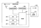
- FIG. 2 is a block diagram showing the configuration of the video receiving apparatus in the present embodiment.
- the video reception device 200 includes a control unit 201, a ROM 202, a RAM 203, a wireless communication circuit unit 204, an antenna 205, a video signal processing unit 206, and an operation unit 207. Moreover, as shown in FIG. 2, each part with which the imaging
- the video reception device 200 is connected to a monitor unit 210 that displays video data.
- the monitor unit 210 is a device different from the video reception device 200, but is not limited thereto.
- the video reception device 200 may include the monitor unit 210.
- the control unit 201 operates in accordance with a program stored in the ROM 202, and controls each unit included in the video reception device 200.
- a ROM 202 is a rewritable non-volatile memory such as a Flash ROM, and stores a program for operating the control unit 201 and various setting information such as communication setting parameters.
- a RAM 203 is a primary storage memory, and is used as a work area used for calculation of the control unit 201 and an area for temporarily storing various settings and the like.
- the wireless communication circuit unit 204 performs wireless communication with another device via the antenna 205.
- the wireless communication circuit unit 204 includes a high frequency circuit unit necessary for wireless communication, a coding / decoding circuit unit, and a buffer memory for storing buffer data at the time of wireless communication.
- An antenna 205 is connected to the antenna 204.
- the wireless communication circuit unit 204 performs wireless communication using a predetermined wireless scheme such as IEEE 802.11.
- the video signal processing unit 206 decompresses the compressed video data received by the wireless communication circuit unit 204, converts it to a video signal such as HDMI or National Television System Committee (NTSC), and outputs the video signal to the monitor unit 210.
- the operation unit 207 includes a plurality of switches such as a power switch, an operation switch, and a setting switch, converts the state and state change of these switches into an electric signal, and outputs the electric signal to the control unit 201.
- the operation unit 207 also includes a plurality of LEDs for reporting the connection state and the communication state with the video transmission device 100.
- the operation unit 207 selects the video transmission device 100 to be selected as the connection destination from the list of the video transmission devices 100 displayed on the monitor unit 210. Acts as an input unit for instructing.
- the monitor unit 210 is a display device such as a liquid crystal display, for example.
- the monitor unit 210 is composed of a liquid crystal display device and its control circuit.
- the monitor unit 210 has a display unit that displays the video data transmitted from the video transmission device 100 and reports the state of wireless connection between the video reception device 200 and the video transmission device 100.
- the monitor unit 210 also includes an EDID storage unit.
- the EDID storage unit 211 is a memory for storing an EDID indicating the capability / specification of the monitor unit 210.
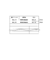
- FIG. 3 is a schematic diagram showing the data structure of the connected device list stored in the ROM 102 of the video transmission apparatus 100 according to this embodiment.
- the connected device list has data items "MAC address (Media Access Control address)", “device name”, and "EDID”, and stores data of each data item in association with each row.
- MAC address Media Access Control address
- the data item “MAC address” stores a MAC address which is information for uniquely identifying the video reception device 200 (wireless communication circuit unit 204).
- the data item “device name” stores the device name of the video reception device 200 uniquely identified by the MAC address stored in the data item “MAC address” in the same row.
- the data item “EDID” stores the EDID of the monitor unit 210 connected to the video reception device 200 uniquely identified by the MAC address stored in the data item “MAC address” of the same row.
- the value stored in the data item "MAC address” in the row 101 is “MAC_01R”, and the value stored in the data item “device name” is "video receiver 1".
- the value stored in the data item "EDID” is "EDID_01”. This is because the device name of the video reception device 200 uniquely identified by the MAC address “MAC_01” is “video reception device 1” and connected to the video reception device 200 uniquely identified by the MAC address “MAC_01”. It indicates that the EDID of the present monitor unit 210 is "EDID_01".
- the other lines are as shown in FIG.
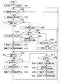
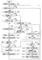
- FIG. 4 is a flowchart showing the operation procedure of the video transmission apparatus 100 in the present embodiment.
- Step S301 When the power of the video transmission device 100 is turned on, the control unit 101 initializes each portion of the video transmission device 100. Thereafter, the process proceeds to step S302.
- Step S302 The video transmission device 100 waits for processing until the wireless communication circuit unit 104 receives a connection request message transmitted from the video reception device 200.
- the process proceeds to step S303. Specifically, when the connection request message is transmitted from the video reception device 200, the wireless communication circuit unit 104 receives the connection request message.
- the control unit 101 determines whether the wireless communication circuit unit 104 has received a connection request message transmitted from the video reception device 200. Then, if the control unit 101 determines that the connection request message has been received, the process proceeds to step S303. Otherwise, the process of step S302 is performed again.
- the connection request message includes the MAC address and the device name of the video reception device 200 that has transmitted the connection request message.
- the control unit 101 of the video transmission device 100 acquires, from the connection request message, the MAC address and the device name of the video reception device 200 that has transmitted the connection request message.
- Step S303 The control unit 101 transmits a connection request response message to the video reception device 200 via the wireless communication circuit unit 104. Then, it progresses to the process of step S304. By executing the processing of step S302 to step S303, the video transmission device 100 establishes a wireless communication connection with the video reception device 200.
- Step S304 The control unit 101 determines whether the MAC address of the video reception device 200 that has been acquired in the process of step S302 and has transmitted the connection request message is included in the connected device list stored in the ROM 102. If the control unit 101 determines that the MAC address of the video reception device 200 that has transmitted the connection request message is included in the connected device list, the process proceeds to step S305; otherwise, the process proceeds to step S306. move on.
- Step S305 The control unit 101 reads out, from the connected device list stored in the ROM 102, the EDID stored in association with the MAC address of the video reception device 200 that has transmitted the connection request message. Then, it progresses to the process of step S311.
- Step S306 The control unit 101 transmits an EDID request message to the video reception device 200 via the wireless communication circuit unit 104. Thereafter, the process proceeds to the process of step S307.
- Step S307 When the EDID of the monitor unit 210 connected to the video reception device 200 is transmitted from the video reception device 200, the wireless communication circuit unit 104 receives the EDID. The control unit 101 determines whether the wireless communication circuit unit 104 has received the EDID transmitted from the video reception device 200. If the control unit 101 determines that the EDID of the monitor unit 210 connected to the video reception device 200 has been received, the process proceeds to step S308; otherwise, the process proceeds to step S309.
- Step S308 The control unit 101 receives the MAC address and the device name of the video reception device 200 that transmitted the connection request message, which are acquired in the processing of step S302, and the video that transmitted the connection request message acquired in the processing of step S307.
- the EDID of the monitor unit 210 connected to the receiving device 200 is associated with the EDID, and stored in the connected device list stored in the ROM 102. Then, it progresses to the process of step S311.
- Step S309 The control unit 101 determines whether a predetermined time has elapsed since the EDID request message was transmitted in the process of step S306. If the control unit 101 determines that the predetermined time has elapsed since the transmission of the EDID request message in the process of step S306, the process proceeds to step S310. Otherwise, the process returns to the process of step S307.
- the predetermined time may be determined in advance or may be set arbitrarily.
- Step S310 The control unit 101 displays a connection error. Thereafter, the process returns to the process of step S302.
- Step S311 The format (format of the video data to be transmitted based on the EDID of the monitor unit 210 connected to the video reception apparatus 200 that has been acquired in step S305 or S307 and has transmitted the connection request message. ) Is determined as a format that this monitor unit 210 can display. Thereafter, the process proceeds to step S312. For example, the format of video data before change is 1920 ⁇ 1080 (60 Hz), and the format of video data after change is 1280 ⁇ 720 (60 Hz).
- Step S312 The video transmission apparatus 100 starts transmission processing of the video data changed to the format determined in the processing of step S311 to the video reception apparatus 200 that has transmitted the connection request message. Thereafter, the process proceeds to step S313. Specifically, the video signal processing unit 106 acquires video data from the video data supply device 110, and changes the format of the acquired video data to the format determined in the process of step S311. Further, the video signal processing unit 106 compresses the video data whose format is changed according to a predetermined method, and outputs the compressed video data to the wireless communication circuit unit 104. The wireless communication circuit unit 104 transmits the video data input from the video signal processing unit 106 to the video reception device 200 that has transmitted the connection request message.
- Step S313 When the disconnection request message is transmitted from the video reception device 200, the wireless communication circuit unit 104 receives the disconnection request message.
- the control unit 101 determines whether the wireless communication circuit unit 104 has received the disconnection request message transmitted from the video reception device 200. If the control unit 101 determines that the disconnection request message has been received, the process proceeds to step S316; otherwise, the process proceeds to step S314.
- Step S314 When stopping transmission of video data, the user of the video transmission device 100 operates the operation unit 107 to input a disconnection instruction.
- the control unit 101 determines whether the operation unit 107 has received an input of a disconnection instruction. If the control unit 101 determines that the input of the disconnection instruction has been received, the process proceeds to step S315; otherwise, the process proceeds to step S317.
- Step S315) The control unit 101 transmits a disconnection request message to the video reception device 200 via the wireless communication circuit unit 104. Thereafter, the process proceeds to step S316.
- Step S316 The control unit 101 stops the operation of the video signal processing unit 106 and the wireless communication circuit unit 104, and ends the video data transmission process. Thereafter, the process returns to the process of step S302.
- Step S317) When the EDID is transmitted from the video reception device 200, the wireless communication circuit unit 104 receives the EDID.
- the control unit 101 determines whether the wireless communication circuit unit 104 has received the EDID transmitted from the video reception device 200. If the control unit 101 determines that the EDID has been received, the process proceeds to step S318; otherwise, the process returns to step S313.
- Step S3128 The control unit 101 stops the operation of the video signal processing unit 106 and the wireless communication circuit unit 104, and ends the video data transmission process. Thereafter, the process proceeds to step S319.
- Step S319) The control unit 101 stores the MAC address of the video reception device 200 that has been stored and acquired in the process of step S302 and has transmitted the connection request message, and the device name and EDID that are stored in association with this MAC address. And are deleted from the connected device list stored in the ROM 102. Thereafter, the control unit 101 acquires the MAC address and the device name of the video reception device 200 that has been acquired in the process of step S302 and has transmitted the connection request message, and the video reception device that has acquired the connection request message in the process of step S317.
- the EDID of the monitor unit 210 connected to 200 is associated with it and stored in the connected device list stored in the ROM 102. Thereafter, the process proceeds to step S320. Instead of deleting the MAC address, the device name, and the EDID and newly storing the MAC address, the device name, and the EDID, the EDID acquired in step S317 may be overwritten.
- Step S320 A format (format) of video data to be transmitted based on the EDID of the monitor unit 210 connected to the video reception apparatus 200 that has transmitted the connection request message, which is acquired in the process of step S317, in the process of step S317. Is determined as a format that can be displayed by the monitor unit 210. Thereafter, the process proceeds to step S321.
- Step S321 The video transmission apparatus 100 starts transmission processing of the video data changed to the format determined in the processing of step S320 to the video reception apparatus 200 that has transmitted the connection request message. Thereafter, the process returns to the process of step S313.
- the communication step described in the claims corresponds to, for example, the processing of steps S302, S303, and S321.
- the image changing step described in the claims corresponds to, for example, the processes of steps S311 and S320.
- the storage step described in the claims corresponds to, for example, the processing of steps S306 to S308, S317, and S319.
- the control steps described in the claims correspond to, for example, the processes of steps S304, S305, and S312.
- the processing of steps S302 to S308, S311, S312, S317, and S319 to S321 in FIG. 4 is an essential component.
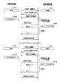
- FIG. 5 is a flowchart showing the operation procedure of the video reception device 200 in the present embodiment.
- Step S401 When the power of the video reception device 200 is turned on, the control unit 101 initializes each portion of the video reception device 200. Then, it progresses to the process of step S402.
- Step S402 When the user of the video reception device 200 selects the video transmission device 100 connected to the video reception device 200, the user operates the operation unit 207 to input a selection instruction of the video reception device 200 to be connected.
- the control unit 201 determines whether the operation unit 207 receives an input of a selection instruction. If the control unit 201 determines that the input of the selection instruction has been received, the process proceeds to step S403. Otherwise, the process of step S402 is performed again.
- Step S403 The control unit 201 is connected to the video transmission apparatus 100 selected by the user via the wireless communication circuit unit 204 based on the selection instruction received by the operation unit 207 in the process of step S403. Send a request message Thereafter, the process proceeds to step S404.
- Step S404 When the connection request response message is transmitted from the video transmission apparatus 100, the wireless communication circuit unit 204 receives the connection request response message.
- the control unit 201 determines whether the wireless communication circuit unit 204 has received a connection request response message transmitted from the video transmission apparatus 100. If the control unit 201 determines that the connection request response message has been received, the process proceeds to step S407; otherwise, the process proceeds to step S405.
- Step S405 The control unit 201 determines whether or not a predetermined time has elapsed since the connection request message was transmitted in the process of step S403. If the control unit 201 determines that the predetermined time has elapsed since the transmission of the connection request message in the process of step S403, the process proceeds to step S406. Otherwise, the process returns to step S404.
- the predetermined time may be determined in advance or may be set arbitrarily.
- Step S406 The control unit 201 displays a connection error. Thereafter, the process returns to the process of step S402.
- Step S407 When the EDID request message is transmitted from the video transmission apparatus 100, the wireless communication circuit unit 204 receives the EDID request message.
- the control unit 201 determines whether the wireless communication circuit unit 204 has received the EDID request message transmitted from the video transmission apparatus 100. If the control unit 201 determines that the EDID request message has been received, the process proceeds to step S408. Otherwise, the process proceeds to step S409.
- Step S408 The control unit 201 reads out the EDID of the monitor unit 210 from the EDID storage unit 211 provided in the monitor unit 210. Then, the control unit 201 transmits the EDID of the monitor unit 210 to the video transmission apparatus 100 via the wireless communication circuit unit 204. Thereafter, the process proceeds to step S412.
- Step S409 When video data is transmitted from the video transmission apparatus 100, the wireless communication circuit unit 204 receives the video data.
- the control unit 201 determines whether the wireless communication circuit unit 204 has received the video data transmitted from the video transmission apparatus 100. If the control unit 201 determines that the video data has been received, the process proceeds to step S412. Otherwise, the process proceeds to step S410.
- Step S410 The control unit 201 determines whether or not a predetermined time has elapsed after determining that the connection request response message has been received in the process of step S404. If the control unit 201 determines that the predetermined time has elapsed since the connection request response message was received in the process of step S404, the process proceeds to step S411. Otherwise, the process returns to the process of step S407.
- the predetermined time may be determined in advance or may be set arbitrarily.
- Step S411 The control unit 201 displays a connection error. Thereafter, the process returns to the process of step S402.
- Step S412 The video reception device 200 starts the reception process of the video data transmitted from the video transmission device 100. Thereafter, the process proceeds to step S413. Specifically, the wireless communication circuit unit 204 receives the video data transmitted from the video transmission device 100. After the wireless communication circuit unit 204 receives and decompresses the compressed video data, the video signal processing unit 206 converts the compressed video data into a video signal such as HDMI or NTSC, and outputs the video signal to the monitor unit 210. The monitor unit 210 displays an image based on the video signal input from the video signal processing unit 206.
- Step S413 When the disconnection request message is transmitted from the video transmission apparatus 100, the wireless communication circuit unit 204 receives the disconnection request message.
- the control unit 201 determines whether the wireless communication circuit unit 204 has received the disconnection request message transmitted from the video transmission apparatus 100. If the control unit 201 determines that the disconnection request message has been received, the processing proceeds to step S416. Otherwise, the processing proceeds to step S414.
- Step S414 The user of the video reception device 200 operates the operation unit 207 to input a disconnection instruction when stopping the reception of video data.
- the control unit 201 determines whether the operation unit 207 has received an input of a disconnection instruction. If the control unit 201 determines that the input of the disconnection instruction has been received, the process proceeds to step S415. Otherwise, the process proceeds to step S417.
- Step S 415) The control unit 201 transmits a disconnection request message to the video transmission apparatus 100 via the wireless communication circuit unit 204. Thereafter, the process proceeds to step S416.
- Step S416) The control unit 201 stops the operation of the wireless communication circuit unit 204 and the video signal processing unit 206, and ends the video data reception process. Thereafter, the process returns to the process of step S402.
- Step S417) If the setting of the monitor unit 210 connected to the video reception device 200 is changed, or if the connected monitor unit 210 is replaced, the monitor unit 210 has different capabilities / specifications.
- the EDID stored in the EDID storage unit 211 of the unit 210 is also changed.
- the control unit 201 reads out the EDID stored in the EDID storage unit 211, and determines whether or not the EDID is different from the EDID read out in the process of step S408. That is, it is determined whether the EDID has changed. If the control unit 201 determines that it is different from the EDID read out in the process of step S408, the process proceeds to the process of step S418. Otherwise, the process returns to the process of step S413.
- the video transmission apparatus 100 transmits an EDID request to the video reception apparatus 200 that has established communication connection for the first time, and the EDID of the monitor unit 210 connected to the video reception apparatus 200. You can get Then, the video transmission device 100 can store the MAC address and device name of the video reception device 200 and the EDID of the monitor unit 210 connected to the video reception device 200 in the connection device list in association with each other.
- the video transmission device 100 establishes communication connection with the video reception device 200 again, the EDID of the monitor unit 210 connected to the video reception device 200 is stored in the connection device list, so the EDID request is made. Get EDID from the connected device list without sending a message. Then, based on the EDID acquired from the connected device list, the video transmission apparatus 100 determines the format of the video data to be transmitted as a format that can be displayed by the monitor unit 210. In addition, the video transmission device 100 starts transmission processing of the video data changed to the format determined based on the EDID to the video reception device 200. As a result, the processing for requesting the EDID can be omitted, and the time until acquiring the EDID can be shortened. As a result, the connection switching time until the start of transmission of video data can be shortened.
- the EDID is also changed because the capability / specification of the monitor unit 210 is different. Ru.
- the video reception device 200 transmits the EDID after the change to the video transmission device 100.
- the later monitor unit 210 can change the format to a reproducible format and transmit it.
- the configuration of the video transmission device 100 in the present embodiment is the same as that of the video transmission device 100 in the first embodiment. Further, the configuration of the video reception device 200 in the present embodiment is the same as the configuration of the video reception device 200 in the first embodiment.
- the setting is changed in the monitor unit 210 connected to the video reception device 200 until the connection is disconnected and communication connection is established again. If the monitor unit 210 is replaced, or if the monitor unit 210 connected is replaced, the EDID stored in the connected device list of the ROM 102 of the video transmission apparatus 100 and the EDID of the monitor unit 210 connected to the video reception apparatus 200 May be different. Therefore, when the video transmission device 100 and the video reception device 200 establish communication connection again, the video transmission device 100 may transmit video data which the monitor unit 210 can not display to the video reception device 200. There is.
- the ROM 202 of the video reception device 200 stores the EDID change list.
- FIG. 6 is a schematic diagram showing the data structure of the EDID change list stored in the ROM 202 of the video reception device 200 in the present embodiment.
- the EDID change list has data items of "MAC address”, "device name”, and "EDID update flag", and stores data of each data item in association with each row.
- a MAC address and an EDID change flag are stored for each video transmission device 100 for which the video reception device 200 has established a wireless connection.
- the data item “MAC address” stores a MAC address which is information for uniquely identifying the video transmission device 100 (wireless communication circuit unit 104).
- the data item “device name” stores the device name of the video transmission device 100 uniquely identified by the MAC address stored in the data item “MAC address” in the same row.
- the data item “EDID update flag” is a video reception device 200 after the wireless connection with the video transmission device 100 uniquely identified by the MAC address stored in the data item “MAC address” in the same row is disconnected. A change flag indicating whether or not the EDID of the monitor unit 210 connected to has been changed is stored.
- the EDID change flag “0” is transmitted to the video reception device 200 after the wireless connection with the video transmission device 100 uniquely identified by the MAC address stored in the data item “MAC address” in the same row is disconnected. This indicates that the EDID of the connected monitor unit 210 has not been changed.
- the EDID change flag “1” is a video reception device after the wireless connection with the video transmission device 100 uniquely identified by the MAC address stored in the data item “MAC address” of the same row is disconnected. It shows that the EDID of the monitor unit 210 connected to 200 has been changed.
- the control unit 201 switches the video transmission device 100 to
- the MAC address uniquely identified, the device name, and the EDID change flag “1” are associated with each other and stored in the EDID change list stored in the ROM 202. Further, the video transmission device 100 and the video reception device 200, which are uniquely identified by the MAC address stored in association with the EDID change flag "1" in the EDID change list stored in the ROM 202, establish the wireless connection again, When the EDID is transmitted to the video transmission device 100, the control unit 201 changes the EDID change flag to "0".
- the connection is disconnected, and connection is established to the video receiving device 200 until communication connection is established again. It can be determined whether the EDID of the monitor unit 210 being changed has been changed.
- the value stored in the data item "MAC address” in the row 201 is “MAC_01T”
- the value stored in the data item “device name” is “video transmission apparatus 1”
- the value stored in the data item "EDID update flag” is "1”.
- the device name of the video transmission apparatus 100 uniquely identified by the MAC address "MAC_01T” is “video transmission apparatus 1”
- wireless connection with the video transmission apparatus 100 uniquely identified by the MAC address "MAC_01T” is made.
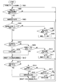
- FIG. 7 is a flowchart showing the operation procedure of the video transmission device 100 in the present embodiment.
- Step S701 When the power of the video transmission device 100 is turned on, the control unit 101 initializes each portion of the video transmission device 100. Thereafter, the process proceeds to step S702.
- Step S702 The video transmission device 100 waits for processing until the wireless communication circuit unit 104 receives a connection request message transmitted from the video reception device 200.
- the process proceeds to step S703. Specifically, when the connection request message is transmitted from the video reception device 200, the wireless communication circuit unit 104 receives the connection request message.
- the control unit 101 determines whether the wireless communication circuit unit 104 has received a connection request message transmitted from the video reception device 200. If the control unit 101 determines that the connection request message has been received, the process proceeds to step S703. Otherwise, the process of step S702 is performed again.
- the connection request message includes the MAC address of the video reception device 200 that has transmitted the connection request message, the device name, and the EDID update flag.
- the control unit 101 of the video transmission device 100 acquires, from the connection request message, the MAC address of the video reception device 200 that has transmitted the connection request message, the device name, and the EDID update flag.
- Step S703 The control unit 101 transmits a connection request response message to the video reception device 200 via the wireless communication circuit unit 104. Thereafter, the process proceeds to step S704.
- Step S704 The control unit 101 determines whether the MAC address of the video reception device 200 that has been acquired in the process of step S702 and has transmitted the connection request message is included in the connected device list stored in the ROM 102. If the control unit 101 determines that the MAC address of the video reception device 200 that has transmitted the connection request message is included in the connected device list, the process proceeds to step S705; otherwise, the process proceeds to step S707. move on.
- Step S705 The control unit 101 determines whether the EDID update flag acquired in the process of step S702 is “1” (whether or not it is set). If the control unit 101 determines that the EDID update flag is “1”, the process proceeds to step S 707. Otherwise, the process proceeds to step S 706.
- the process of steps S706 to S722 is the same process as the process of steps S305 to S321 in the first embodiment.
- the communication steps described in the claims correspond to, for example, the processes of steps S702, S703, and S722.
- the image changing step described in the claims corresponds to, for example, the processing of steps S712 and S721.
- the storage step described in the claims corresponds to, for example, the processing of steps S707 to S709, S718, and S720.
- the control steps described in the claims correspond to, for example, the processes of steps S704 to S706 and S713.
- the processing of steps S702 to S709, S712, S713, S718, and S720 to S722 in FIG. 7 is an essential component.
- FIG. 8 is a flowchart showing the operation procedure of the video reception device 200 in the present embodiment.
- Step S801 When the power of the video reception device 200 is turned on, the control unit 101 initializes each unit included in the video reception device 200. Thereafter, the process proceeds to step S802.
- Step S802 When the user of the video reception device 200 selects the video transmission device 100 connected to the video reception device 200, the user operates the operation unit 207 to input a selection instruction of the video reception device 200 to be connected.
- the control unit 201 determines whether the operation unit 207 receives an input of a selection instruction. If the control unit 201 determines that the input of the selection instruction has been received, the process proceeds to step S 803. Otherwise, the process of step S 802 is performed again.
- Step S803 The control unit 201 determines whether the EDID of the monitor unit 210 connected to the video reception device 200 has been changed after the wireless connection with the video transmission device 100 selected in the process of step S802 is disconnected. Determine if If the control unit 201 determines that the EDID of the monitor unit 210 connected to the video reception device 200 is changed after the wireless connection with the video transmission device 100 selected in the process of step S802 is disconnected. The process proceeds to step S804, and otherwise proceeds to step S805. Also, when connecting to the video transmission apparatus 100 selected in the process of step S802 for the first time, the process proceeds to the process of step S804.
- Step S804 The control unit 201 associates the MAC address and device name of the video transmission apparatus 100 selected in the process of step S802 with the EDID change flag "1" and stores the result in the EDID change list stored in the ROM 202. . If the EDID change list stored in the ROM 202 already stores the MAC address and the device name of the video transmission device 100 selected in the process of step S802, the EDID update flag associated with the MAC address is It is assumed that 1 ". Thereafter, the process proceeds to step S805.
- steps S805 to S808 are similar to the processes of steps S403 to S406 in the first embodiment.
- Step S809 When the EDID request message is transmitted from the video transmission apparatus 100, the wireless communication circuit unit 204 receives the EDID request message. The control unit 201 determines whether the wireless communication circuit unit 204 has received the EDID request message transmitted from the video transmission apparatus 100. If the control unit 201 determines that the EDID request message has been received, the process proceeds to step S810; otherwise, the process proceeds to step S812.
- Step S810 The control unit 201 reads out the EDID of the monitor unit 210 from the EDID storage unit 211 provided in the monitor unit 210. Then, the control unit 201 transmits the EDID of the monitor unit 210 to the video transmission apparatus 100 via the wireless communication circuit unit 204. Thereafter, the process proceeds to step S811.
- Step S811 The control unit 201 controls the EDID update flag (stored in the EDID change list stored in the ROM 202) associated with the MAC address and the device name of the video transmission device 100 selected in the process of step S802. Is set to "0". Thereafter, the process proceeds to step S815.
- the process of step S812 to step S821 is the same process as the process of step S409 to step S418 in the first embodiment.
- the control unit 201 associates the MAC address and the device name for uniquely identifying the video transmission device 100 with the EDID change flag “1”, and stores them in the EDID change list stored in the ROM 202. Further, the video transmission device 100 and the video reception device 200, which are uniquely identified by the MAC address stored in association with the EDID change flag "1" in the EDID change list stored in the ROM 202, establish the wireless connection again, When the EDID is transmitted to the video transmission device 100, the control unit 201 changes the EDID change flag to "0".
- the connection is disconnected, and connection is established to the video receiving device 200 until communication connection is established again. It can be determined whether the EDID of the monitor unit 210 being changed has been changed.
- the video transmission device 100 receives the EDID change flag from the video reception device 200, and after the EDID update flag is “1”, that is, establishing the communication connection, disconnecting the connection and establishing the communication connection again. Then, it is determined whether the EDID of the monitor unit 210 connected to the video reception device 200 has been changed. Then, after establishing the communication connection, when it is determined that the EDID of the monitor unit 210 connected to the video reception device 200 has been changed before the communication connection is disconnected again, the video transmission device 100 determines , Acquire the EDID again from the video reception device 200.
- the video reception device 200 transmits a connection request message to the video transmission device 100, and the video transmission device 100 transmits a connection request response message to the connection request message to the video reception device 200.
- the video transmission device 100 and the video reception device 200 establish the wireless communication connection, the present invention is not limited thereto.
- the video transmission apparatus 100 transmits a connection request message to the video reception apparatus 200, and the video reception apparatus 200 transmits a connection request response message to the connection request message to the video transmission apparatus 100, thereby the video transmission apparatus A wireless communication connection may be established between 100 and the video receiving device 200.
- the whole or part of the functions of the units included in the video transmission apparatus 100 described above, or the whole or part of the functions of the units included in the video reception apparatus 200 may use computer readable programs for realizing the functions. It may be realized by recording, reading a program recorded on the recording medium into a computer system, and executing the program.
- the “computer system” mentioned here includes an OS and hardware such as peripheral devices.
- the “computer-readable recording medium” refers to a storage unit such as a flexible disk, a magneto-optical disk, a ROM, a portable medium such as a CD-ROM, or a hard disk built in a computer system. Furthermore, the "computer-readable recording medium” dynamically holds a program for a short time, like a communication line when transmitting a program via a network such as the Internet or a communication line such as a telephone line.
- the medium may also include a medium that holds a program at a fixed time, such as a medium, and a volatile memory in the computer system serving as a server or a client in that case.
- the program may be for realizing a part of the functions described above, or may be realized in combination with the program already recorded in the computer system.
- the communication unit establishes the wireless communication connection with the display device having the display unit for displaying the first image in time series and before the wireless communication connection is disconnected.
- the first image is wirelessly transmitted in time series to the display device.
- the image changing unit changes the first format of the first image to be wirelessly transmitted to the display device based on setting information of the display unit of the display device which has established the wireless communication connection.
- the storage unit stores a display device identifier uniquely identifying the display device and setting information of the display portion of the display device in association with each other.
- the control unit stores the display device identifier and the setting information in association with each other when establishing a wireless communication connection with the display device, the control unit does not request the display device to transmit the setting information, and stores the setting information.
- the image change unit changes the first format of the first image to the second format based on the setting information stored in the unit, and the second image changed to the second format is wirelessly transmitted to the communication unit. Send it.
- the process of acquiring the setting information of the display unit can be omitted, so that the time required to switch the wireless connection between the video receiving device and the video transmitting device can be further shortened.
- Video transmission device 101 201 ⁇ Control section 102, 202 ⁇ ROM 103, 203 ... RAM 104, 204 ... wireless communication circuit unit 105, 205 ... antenna 106, 206 ... video signal processing unit 107, 207 ... operation unit 200 ... video reception device 110 ... video data supply device 210: Monitor 211: EDID storage
Landscapes
- Engineering & Computer Science (AREA)
- Multimedia (AREA)
- Signal Processing (AREA)
- Computer Networks & Wireless Communication (AREA)
- Physics & Mathematics (AREA)
- Computer Hardware Design (AREA)
- General Physics & Mathematics (AREA)
- Theoretical Computer Science (AREA)
- Two-Way Televisions, Distribution Of Moving Picture Or The Like (AREA)
- Mobile Radio Communication Systems (AREA)
Priority Applications (3)
| Application Number | Priority Date | Filing Date | Title |
|---|---|---|---|
| EP12847058.0A EP2779639A4 (en) | 2011-11-08 | 2012-11-08 | IMAGE TRANSMISSION DEVICE, IMAGE TRANSMISSION METHOD, AND PROGRAM THEREOF |
| CN201280052808.3A CN104025613B (zh) | 2011-11-08 | 2012-11-08 | 图像发送装置、图像发送方法和程序 |
| US14/266,400 US8988613B2 (en) | 2011-11-08 | 2014-04-30 | Image transmission device, image transmission method, and computer-readable device |
Applications Claiming Priority (2)
| Application Number | Priority Date | Filing Date | Title |
|---|---|---|---|
| JP2011-244352 | 2011-11-08 | ||
| JP2011244352A JP2013102325A (ja) | 2011-11-08 | 2011-11-08 | 画像送信装置、画像送信方法およびプログラム |
Related Child Applications (1)
| Application Number | Title | Priority Date | Filing Date |
|---|---|---|---|
| US14/266,400 Continuation US8988613B2 (en) | 2011-11-08 | 2014-04-30 | Image transmission device, image transmission method, and computer-readable device |
Publications (1)
| Publication Number | Publication Date |
|---|---|
| WO2013069738A1 true WO2013069738A1 (ja) | 2013-05-16 |
Family
ID=48290108
Family Applications (1)
| Application Number | Title | Priority Date | Filing Date |
|---|---|---|---|
| PCT/JP2012/079002 Ceased WO2013069738A1 (ja) | 2011-11-08 | 2012-11-08 | 画像送信装置、画像送信方法およびプログラム |
Country Status (5)
| Country | Link |
|---|---|
| US (1) | US8988613B2 (enExample) |
| EP (1) | EP2779639A4 (enExample) |
| JP (1) | JP2013102325A (enExample) |
| CN (1) | CN104025613B (enExample) |
| WO (1) | WO2013069738A1 (enExample) |
Cited By (1)
| Publication number | Priority date | Publication date | Assignee | Title |
|---|---|---|---|---|
| JP2023039048A (ja) * | 2021-09-08 | 2023-03-20 | シャープ株式会社 | 表示制御システムおよび表示入力管理方法 |
Families Citing this family (3)
| Publication number | Priority date | Publication date | Assignee | Title |
|---|---|---|---|---|
| JP2014082545A (ja) * | 2012-10-12 | 2014-05-08 | Funai Electric Co Ltd | 録画再生装置およびその制御方法 |
| US20170078739A1 (en) * | 2014-03-12 | 2017-03-16 | Lg Electronics Inc. | Device and method for transmitting and receiving data using hdmi |
| CN107896314B (zh) * | 2017-11-10 | 2019-12-24 | 浙江大华技术股份有限公司 | 一种视频传输方法及设备 |
Citations (7)
| Publication number | Priority date | Publication date | Assignee | Title |
|---|---|---|---|---|
| JP2007108198A (ja) * | 2005-10-11 | 2007-04-26 | Sony Corp | 情報処理装置および方法、並びにプログラム |
| JP2008035517A (ja) | 2006-02-14 | 2008-02-14 | Matsushita Electric Ind Co Ltd | 無線通信システム |
| JP2009049787A (ja) * | 2007-08-21 | 2009-03-05 | Funai Electric Co Ltd | 電子機器 |
| JP2009182912A (ja) * | 2008-02-01 | 2009-08-13 | Hitachi Ltd | 映像音声再生装置 |
| JP2010098378A (ja) * | 2008-10-14 | 2010-04-30 | Sharp Corp | 無線伝送システム |
| JP2011015245A (ja) * | 2009-07-03 | 2011-01-20 | Hitachi Consumer Electronics Co Ltd | 映像送信装置及び映像受信装置 |
| WO2011040007A1 (ja) * | 2009-10-01 | 2011-04-07 | パナソニック株式会社 | 無線通信システム、映像装置用アダプタ装置、映像装置、および、無線通信システムの制御方法 |
Family Cites Families (7)
| Publication number | Priority date | Publication date | Assignee | Title |
|---|---|---|---|---|
| US7499030B2 (en) * | 2001-11-30 | 2009-03-03 | Texas Instruments Incorporated | Graphics initialization for wireless display devices |
| CN101385278B (zh) * | 2006-02-14 | 2011-06-22 | 松下电器产业株式会社 | 无线通信系统 |
| CN201115245Y (zh) * | 2007-09-04 | 2008-09-10 | 享乐科技股份有限公司 | 具温度感测的散热垫 |
| WO2009119095A1 (ja) * | 2008-03-27 | 2009-10-01 | パナソニック株式会社 | 無線通信装置 |
| JP2009284047A (ja) * | 2008-05-20 | 2009-12-03 | Panasonic Corp | ソース装置用アダプタ装置及びソース装置用アダプタ装置の制御方法 |
| JP5351960B2 (ja) * | 2009-05-14 | 2013-11-27 | パナソニック株式会社 | ビデオデータの伝送方法 |
| JP5520964B2 (ja) * | 2009-11-24 | 2014-06-11 | パナソニック株式会社 | ソース装置用アダプタ装置及びソース装置用アダプタ装置の制御方法 |
-
2011
- 2011-11-08 JP JP2011244352A patent/JP2013102325A/ja active Pending
-
2012
- 2012-11-08 WO PCT/JP2012/079002 patent/WO2013069738A1/ja not_active Ceased
- 2012-11-08 EP EP12847058.0A patent/EP2779639A4/en not_active Withdrawn
- 2012-11-08 CN CN201280052808.3A patent/CN104025613B/zh not_active Expired - Fee Related
-
2014
- 2014-04-30 US US14/266,400 patent/US8988613B2/en active Active
Patent Citations (7)
| Publication number | Priority date | Publication date | Assignee | Title |
|---|---|---|---|---|
| JP2007108198A (ja) * | 2005-10-11 | 2007-04-26 | Sony Corp | 情報処理装置および方法、並びにプログラム |
| JP2008035517A (ja) | 2006-02-14 | 2008-02-14 | Matsushita Electric Ind Co Ltd | 無線通信システム |
| JP2009049787A (ja) * | 2007-08-21 | 2009-03-05 | Funai Electric Co Ltd | 電子機器 |
| JP2009182912A (ja) * | 2008-02-01 | 2009-08-13 | Hitachi Ltd | 映像音声再生装置 |
| JP2010098378A (ja) * | 2008-10-14 | 2010-04-30 | Sharp Corp | 無線伝送システム |
| JP2011015245A (ja) * | 2009-07-03 | 2011-01-20 | Hitachi Consumer Electronics Co Ltd | 映像送信装置及び映像受信装置 |
| WO2011040007A1 (ja) * | 2009-10-01 | 2011-04-07 | パナソニック株式会社 | 無線通信システム、映像装置用アダプタ装置、映像装置、および、無線通信システムの制御方法 |
Non-Patent Citations (1)
| Title |
|---|
| See also references of EP2779639A4 |
Cited By (2)
| Publication number | Priority date | Publication date | Assignee | Title |
|---|---|---|---|---|
| JP2023039048A (ja) * | 2021-09-08 | 2023-03-20 | シャープ株式会社 | 表示制御システムおよび表示入力管理方法 |
| JP7606948B2 (ja) | 2021-09-08 | 2024-12-26 | シャープ株式会社 | 表示制御システムおよび表示入力管理方法 |
Also Published As
| Publication number | Publication date |
|---|---|
| EP2779639A1 (en) | 2014-09-17 |
| EP2779639A4 (en) | 2015-01-21 |
| JP2013102325A (ja) | 2013-05-23 |
| US8988613B2 (en) | 2015-03-24 |
| CN104025613A (zh) | 2014-09-03 |
| US20140232936A1 (en) | 2014-08-21 |
| CN104025613B (zh) | 2017-06-06 |
Similar Documents
| Publication | Publication Date | Title |
|---|---|---|
| US8713208B2 (en) | Image display device and method of changing first EDID with second EDID wherein the second EDID information is compatible with image display device | |
| JP6423172B2 (ja) | 無線内視鏡システム、表示装置、及びプログラム | |
| JP6987556B2 (ja) | 通信装置、情報処理方法及びプログラム | |
| US10237508B2 (en) | Method and device for displaying boot screen | |
| WO2013069738A1 (ja) | 画像送信装置、画像送信方法およびプログラム | |
| CN115297347B (zh) | 影像显示装置 | |
| JP2015033074A (ja) | 通信機器及び方法、並びにプログラム | |
| CN101505379B (zh) | 视频显示设备和视频输出设备及其控制方法 | |
| EP2653963A2 (en) | Image communication apparatus, image communication server and image processing method for image communication | |
| JP2012160020A (ja) | 無線装置、表示装置及び受信制御方法 | |
| CN103339955B (zh) | 无线终端以及无线系统 | |
| JP2013251906A5 (enExample) | ||
| WO2016148102A1 (ja) | 通信装置、通信システム及び通信方法 | |
| US20150067510A1 (en) | Display system, recording medium, and selection control method | |
| KR20150028501A (ko) | 리모트 컨트롤러 및 그 제어 방법 | |
| JP2023058766A (ja) | シンク機器及び情報処理方法 | |
| JP6631087B2 (ja) | 制御端末、オーディオシステムおよびオーディオ機器制御プログラム | |
| JP2016174221A (ja) | 通信装置、通信システム及び通信方法 | |
| JP7073570B2 (ja) | 通信装置、通信装置の制御方法及びプログラム | |
| JP2012004964A (ja) | 表示装置 | |
| JP2016174220A (ja) | 通信装置、通信システム及び通信方法 | |
| EP2919492A1 (en) | Wireless transmission terminal, wireless receiving terminal, wireless communication system, wireless communication method, and program | |
| JP2022093552A (ja) | 通信装置、通信装置の制御方法及びプログラム | |
| JP2013038820A (ja) | 映像処理装置及びその制御方法、並びに映像出力装置及びその制御方法 | |
| JP2016197846A (ja) | 通信装置、制御方法及びプログラム |
Legal Events
| Date | Code | Title | Description |
|---|---|---|---|
| 121 | Ep: the epo has been informed by wipo that ep was designated in this application |
Ref document number: 12847058 Country of ref document: EP Kind code of ref document: A1 |
|
| REEP | Request for entry into the european phase |
Ref document number: 2012847058 Country of ref document: EP |
|
| WWE | Wipo information: entry into national phase |
Ref document number: 2012847058 Country of ref document: EP |
|
| NENP | Non-entry into the national phase |
Ref country code: DE |