WO2013064396A1 - Cuisinière à chauffage par induction - Google Patents
Cuisinière à chauffage par induction Download PDFInfo
- Publication number
- WO2013064396A1 WO2013064396A1 PCT/EP2012/070979 EP2012070979W WO2013064396A1 WO 2013064396 A1 WO2013064396 A1 WO 2013064396A1 EP 2012070979 W EP2012070979 W EP 2012070979W WO 2013064396 A1 WO2013064396 A1 WO 2013064396A1
- Authority
- WO
- WIPO (PCT)
- Prior art keywords
- plate
- heat sink
- sensor
- switching elements
- induction heating
- Prior art date
Links
Images


Classifications
-
- H—ELECTRICITY
- H05—ELECTRIC TECHNIQUES NOT OTHERWISE PROVIDED FOR
- H05B—ELECTRIC HEATING; ELECTRIC LIGHT SOURCES NOT OTHERWISE PROVIDED FOR; CIRCUIT ARRANGEMENTS FOR ELECTRIC LIGHT SOURCES, IN GENERAL
- H05B6/00—Heating by electric, magnetic or electromagnetic fields
- H05B6/02—Induction heating
- H05B6/10—Induction heating apparatus, other than furnaces, for specific applications
- H05B6/12—Cooking devices
- H05B6/1209—Cooking devices induction cooking plates or the like and devices to be used in combination with them
- H05B6/1245—Cooking devices induction cooking plates or the like and devices to be used in combination with them with special coil arrangements
- H05B6/1263—Cooking devices induction cooking plates or the like and devices to be used in combination with them with special coil arrangements using coil cooling arrangements
-
- H—ELECTRICITY
- H05—ELECTRIC TECHNIQUES NOT OTHERWISE PROVIDED FOR
- H05B—ELECTRIC HEATING; ELECTRIC LIGHT SOURCES NOT OTHERWISE PROVIDED FOR; CIRCUIT ARRANGEMENTS FOR ELECTRIC LIGHT SOURCES, IN GENERAL
- H05B6/00—Heating by electric, magnetic or electromagnetic fields
- H05B6/02—Induction heating
- H05B6/06—Control, e.g. of temperature, of power
- H05B6/062—Control, e.g. of temperature, of power for cooking plates or the like
-
- H—ELECTRICITY
- H05—ELECTRIC TECHNIQUES NOT OTHERWISE PROVIDED FOR
- H05B—ELECTRIC HEATING; ELECTRIC LIGHT SOURCES NOT OTHERWISE PROVIDED FOR; CIRCUIT ARRANGEMENTS FOR ELECTRIC LIGHT SOURCES, IN GENERAL
- H05B2213/00—Aspects relating both to resistive heating and to induction heating, covered by H05B3/00 and H05B6/00
- H05B2213/04—Heating plates with overheat protection means
Definitions
- the present invention relates to an induction heating cooker that is provided to operate in a safe manner.
- the induction heating cooker functions according to the principle of heating a cast iron or steel ferromagnetic cooking container with the magnetic field effect generated by the induction coil.
- the energy efficiency of induction heating cookers is considerably high since the heat required for cooking is not generated in the gas or electric burners on the cooker but directly in the cooking container.
- electronic switching elements such as the IGBT (Insulated Gate Bipolar Transistor) or the diode bridge on the circuit board and therefore the said switching elements are excessively heated.
- An effective cooling system is required so that the switching elements can operate safely.
- the switching elements carrying high current and where the most overheating is observed are cooled by being connected to a heat sink and by delivering air thereto by means of a fan.
- the temperature of the switching elements In order to assure that the induction heating cooker operates in safe conditions, the temperature of the switching elements must be kept under control. When the switching elements reach the critical temperature defined by the producer, the current passed therethrough is cut off by the control unit.
- the temperature of the switching element (4’) is tried to be kept under control by connecting a sensor (2’) onto the heat sink (3’).
- a sensor (2’) onto the heat sink (3’) since the temperatures of the switching element (4’) and the heat sink (3’) will be different from each other, an efficient and safe control mechanism cannot be provided. Since the sensor (2’) contacts onto the heat sink (3’), the temperature measured by the sensor (2’) is lower than the actual temperature of the switching element (4’). Since the turning off of cooker is decided depending on the temperature values measured by the sensor (2’), it is crucial to perform a temperature control that does not compromise from cooking efficiency and also provides safe operating conditions.
- a cooking device comprising a guide that is disposed on the heat sink so as to cover at least some portion of the heat sink and that provides some of the cold air to be guided onto the switching elements.
- the aim of the present invention is the realization of an induction heating cooker that is provided to operate in a safe manner by providing the temperature of the switching elements to be measured as close as possible to the actual values.
- the induction heating cooker realized in order to attain the aim of the present invention, explicated in the first claim and the respective claims thereof comprises at least one heat sink whereon the switching elements are placed, providing the cooling of the switching elements, a plate produced from a heat-conducting material, placed on the heat sink so that the switching elements are therebetween, a sensor disposed on the plate and used for measuring temperature and a control unit that provides the power to be transmitted to the switching elements depending on the temperature data transmitted by the sensor.
- the switching elements heat due to the current passing therethrough.
- the heat sink provides the cooling of the switching elements by spreading the cold air blown by the fan.
- the plate is placed onto the switching elements so that there is heat transfer therebetween by means of conduction. Thus, when the switching elements heat, the plate heats as well.
- the temperature of the plate is almost equal to the average temperature of the switching elements.
- the sensor By means of the sensor being placed onto the plate, the sensor is provided to measure the average temperature of the switching elements.
- the control unit cuts off the current passing through the switching elements and prevents the switching elements from being damaged. With the control unit controlling the transmission of power to the switching elements according to the temperature data transmitted by the sensor, the induction heating cooker is provided to operate in safer operating conditions with respect to the user.
- the switching elements are fastened onto the heat sink and the plate is mounted onto the switching elements so as to contact the switching elements.
- the plate is placed between the sensor and the heat sink so as to prevent the contact of these two.
- the sensor is prevented from directly contacting the heat sink. Consequently, the sensor is enabled to measure the temperature of the plate heating up due to the heat conducted to the plate from the switching elements.
- the plate is placed so as to longitudinally extend over the heat sink.
- the heat passing to the plate from the switching elements placed side by side onto the heat sink is provided to be homogeneously distributed on the plate.
- the senor is placed at the center of the plate so that the switching elements remain at both sides of the sensor.
- the heat passing from the switching elements to the plate is provided to be better homogenized.
- the sensor is provided to measure the heat effectively distributed on the plate.
- more than one fixing hole is arranged on the plate.
- the switching elements After being positioned between the heat sink and the plate, the switching elements are fastened to the heat sink by means of fixing elements.
- the fixing element is respectively passed through the fixing hole and the switching element to be fixed onto the heat sink.
- the sensor is also positioned on the plate and fastened onto the plate by means of a fixing element. The other end of the fixing element extends towards the heat sink.
- the plate is produced from rectangular sheet metal. With a much shorter width with respect to its length, the plate is in a flat rod shape.
- the plate is produced from aluminum.
- the heat conduction feature of the plate is improved.
- an induction heating cooker is realized, wherein the temperature of the switching elements are measured by means of the sensor on the plate placed onto the switching elements.
- Figure 1 – is the schematic view of an induction heating cooker.
- Figure 2 — is the perspective view of the heat sink, the switching elements, the sensor and the plate in the state of the art.
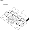
- Figure 3 – is the perspective view of a heat sink, a fan, switching elements, a sensor and a plate.
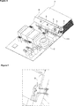
- Figure 4 – is the perspective view of a heat sink, switching elements, a sensor and a plate.
- Figure 5 — is the perspective view of a plate.
- Figure 6 – is the partial perspective view of a heat sink, switching elements, a sensor and a plate.
- Figure 7 — is the view of detail A in Figure 6.
- the induction heating cooker (1) comprises an upper table (3) produced from materials such as glass or ceramic, more than one induction coil (2) disposed under the upper plate (3), providing the cooking container of ferromagnetic feature placed thereon to be heated by the magnetic field it generates, more than one circuit board (4) providing the induction coils (2) to be energized, more than one switching element (5) connected to the circuit board (4), carrying high value electric current and heating due to effect of the current it carries, a fan (6) disposed under the upper plate (3) and at least one heat sink (7) that provides the cooling of the switching elements (5) placed thereon by distributing the air blown by the fan (6).
- the switching elements (5) are elements carrying high-value electric current, overheating due to the current, such as IGBT (Insulated Gate Bipolar Transistor) and diode bridge. Being placed onto the heat sink (7) distributing the cold air blown by the fan (6), the switching elements (5) are prevented from overheating thanks to the heat transfer between the switching elements (5) and the heat sink (7).
- IGBT Insulated Gate Bipolar Transistor
- the induction heating cooker (1) of the present invention furthermore comprises a plate (8) produced from a heat-conducting material, placed on the heat sink (7) so as to contact the switching elements (5), at least one sensor (9) disposed on the plate (8) and used for measuring the temperature of the plate (8) and a control unit (12) that controls the energizing of the switching elements (5) depending on the temperature data transmitted by the sensor (9). Since the switching elements (5) contact both the heat sink (7) and the plate (8), heat transfer occurs between the switching element (5), the heat sink (7) and the plate (8) by means of conduction. Since the plate (8) contacts every one of the switching elements (5), the temperature of the plate (8) is almost equal to the average temperature of the switching elements (5).
- the plate (8) undertakes the role of homogenizing the temperatures of the switching elements (5).
- the sensor (9) By means of the sensor (9) being placed onto the plate (8), the sensor (9) is provided to measure the average temperature of the plate (8), hence of the switching elements (5).
- the control unit (12) controls the current transmitted to the switching elements (5) depending on the temperature values transmitted by the sensor (9). When the temperature value measured by the sensor (9) reaches the critical value determined by the producer, the control unit (12) cuts off the current passing through the switching elements (5).
- the switching elements (5) are prevented from overheating, providing safe operating conditions with respect to the user.
- the switching element (5) is fastened onto the heat sink (7) so as to be between the heat sink (7) and the plate (8).
- the switching elements (5) contact both the heat sink (7) and the plate (8). Accordingly, when current passes through one of the switching elements (5), heat transfer occurs between that switching element (5) and the plate (8).
- the sensor (9) on the plate (8) the temperature of the plate (8), hence of the switching element (5) is measured.
- the plate (8) is placed between the sensor (9) and the heat sink (7).
- the sensor (9) is prevented from directly contacting the heat sink (7).
- heat transfer between the sensor (9) and the heat sink (7) is prevented, and the sensor (9) is prevented from getting cold by being affected by the cold air spreading from the heat sink (7). Consequently, the sensor (9) is provided to measure the temperature of the plate (8) heating due to the heat passing from the switching elements (5) to the plate (8).
- the plate (8) is longitudinally placed over the heat sink (7). Since the switching elements (5) are placed in a side-by-side manner onto the heat sink (7), the plate (8) is longitudinally placed onto the heat sink (7) so as to contact every one of the switching elements (5).
- the senor (9) is placed almost at the center of the plate (8).
- the sensor (9) is placed onto the plate (8) so that the switching elements (5) are at both sides of the sensor (9).
- the heat emanated from the switching elements (5) is provided to be homogeneously distributed over the plate (8).
- the induction heating cooker (1) comprises more than one fixing hole (10, 100) arranged on the plate (8) and more than one fixing element (11, 111) that provides the switching element (5) or the sensor (9) to be fastened onto the heat sink (7) with one end being fixed to the heat sink (7) by being passed through the fixing hole (10, 100) and over the switching element (5) or the sensor (9).
- the switching elements (5) are placed onto the heat sink (7) and the fixing element (11) is fixed onto the heat sink (7) by being passed through the fixing hole (10) on the plate (8) and over the switching element (5).
- the sensor (9) is preferably in circular or semi-circular form.
- the sensor (9) is placed onto the fixing hole (100) on the plate (8) and the fixing element (111) is fixed onto the heat sink (7) by being passed over the sensor (9).
- the mounting of the sensor (9) to the plate (8) is realized.
- the plate (8) is produced from rectangular sheet metal.
- the plate (8) is produced from aluminum. Since the aluminum is a material with high heat conduction coefficient, the heat transfer from the switching elements (5) to the plate (8) is improved.
- the average temperature of the switching elements (5) is provided to be measured by placing the sensor (9) on a plate (8) whereto heat transfer is provided from the heat sink (7) and the switching elements (5).
- the sensor (9) is placed on a plate (8) whereto heat transfer is provided from the heat sink (7) and the switching elements (5).
Landscapes
- Physics & Mathematics (AREA)
- Electromagnetism (AREA)
- Induction Heating Cooking Devices (AREA)
- Electric Stoves And Ranges (AREA)
Abstract
L'invention concerne une cuisinière à chauffage à induction (1) comprenant : une table supérieure (3) produite à partir de matériaux, tels que du verre ou de la céramique ; au moins une bobine d'induction (2) disposée sous la table supérieure (3) fournissant au récipient de cuisson placé sur cette dernière une caractéristique ferromagnétique permettant de le chauffer au moyen du champ magnétique qu'elle génère ; au moins une carte de circuit imprimé (4) permettant d'activer les bobines d'induction (2) ; au moins un élément de commutation (5) connecté à la carte de circuit imprimé (4) acheminant un courant électrique à valeur élevée et la chaleur résultant de l'effet du courant qu'il achemine ; un ventilateur (6) disposé sous la table supérieure (3) ; et au moins un puits de chaleur (7) permettant de refroidir les éléments de commutation (5) placés sur ce dernier par distribution de l'air soufflé par le ventilateur (6).
Priority Applications (2)
| Application Number | Priority Date | Filing Date | Title |
|---|---|---|---|
| EP12784223.5A EP2774454B1 (fr) | 2011-11-04 | 2012-10-23 | Cuisinière à chauffage par induction |
| ES12784223.5T ES2694569T3 (es) | 2011-11-04 | 2012-10-23 | Cocina de calentamiento por inducción |
Applications Claiming Priority (2)
| Application Number | Priority Date | Filing Date | Title |
|---|---|---|---|
| TRA2011/11058 | 2011-11-04 | ||
| TR201111058 | 2011-11-04 |
Publications (1)
| Publication Number | Publication Date |
|---|---|
| WO2013064396A1 true WO2013064396A1 (fr) | 2013-05-10 |
Family
ID=47172597
Family Applications (1)
| Application Number | Title | Priority Date | Filing Date |
|---|---|---|---|
| PCT/EP2012/070979 WO2013064396A1 (fr) | 2011-11-04 | 2012-10-23 | Cuisinière à chauffage par induction |
Country Status (4)
| Country | Link |
|---|---|
| EP (1) | EP2774454B1 (fr) |
| ES (1) | ES2694569T3 (fr) |
| TR (1) | TR201718646T4 (fr) |
| WO (1) | WO2013064396A1 (fr) |
Cited By (7)
| Publication number | Priority date | Publication date | Assignee | Title |
|---|---|---|---|---|
| US20160374155A1 (en) * | 2015-06-22 | 2016-12-22 | Lg Electronics Inc. | Induction heat cooking apparatus and method for driving the same |
| WO2018086935A1 (fr) * | 2016-11-08 | 2018-05-17 | Arcelik Anonim Sirketi | Cuisinière à induction |
| JP2019153491A (ja) * | 2018-03-05 | 2019-09-12 | 三菱電機株式会社 | 加熱調理器 |
| US10517148B2 (en) * | 2015-06-23 | 2019-12-24 | Lg Electronics Inc. | Induction heat cooking apparatus and method for driving the same |
| FR3105908A1 (fr) * | 2019-12-31 | 2021-07-02 | Groupe Brandt | Procédé de commande en puissance et table de cuisson mettant en œuvre ledit procédé |
| EP3962239A1 (fr) * | 2020-08-31 | 2022-03-02 | Arçelik Anonim Sirketi | Appareil de cuisson à chauffage par induction présentant une meilleure performance de refroidissement |
| US11871499B2 (en) | 2020-11-05 | 2024-01-09 | Whirlpool Corporation | Induction cooking apparatus with heatsink and method of assembly |
Families Citing this family (1)
| Publication number | Priority date | Publication date | Assignee | Title |
|---|---|---|---|---|
| WO2024056394A1 (fr) * | 2022-09-13 | 2024-03-21 | BSH Hausgeräte GmbH | Dispositif d'appareil électroménager |
Citations (3)
| Publication number | Priority date | Publication date | Assignee | Title |
|---|---|---|---|---|
| EP1248506A2 (fr) * | 2001-04-03 | 2002-10-09 | Emerson Electric Co. | Radiateur pour des composants sur un circuit imprimé |
| EP1936283A2 (fr) | 2006-12-14 | 2008-06-25 | LG Electronics Inc. | Appareil de cuisine |
| JP2011198621A (ja) * | 2010-03-19 | 2011-10-06 | Mitsubishi Electric Corp | 電磁調理器 |
-
2012
- 2012-10-23 EP EP12784223.5A patent/EP2774454B1/fr active Active
- 2012-10-23 WO PCT/EP2012/070979 patent/WO2013064396A1/fr active Application Filing
- 2012-10-23 ES ES12784223.5T patent/ES2694569T3/es active Active
- 2012-10-23 TR TR2017/18646T patent/TR201718646T4/tr unknown
Patent Citations (3)
| Publication number | Priority date | Publication date | Assignee | Title |
|---|---|---|---|---|
| EP1248506A2 (fr) * | 2001-04-03 | 2002-10-09 | Emerson Electric Co. | Radiateur pour des composants sur un circuit imprimé |
| EP1936283A2 (fr) | 2006-12-14 | 2008-06-25 | LG Electronics Inc. | Appareil de cuisine |
| JP2011198621A (ja) * | 2010-03-19 | 2011-10-06 | Mitsubishi Electric Corp | 電磁調理器 |
Cited By (10)
| Publication number | Priority date | Publication date | Assignee | Title |
|---|---|---|---|---|
| US20160374155A1 (en) * | 2015-06-22 | 2016-12-22 | Lg Electronics Inc. | Induction heat cooking apparatus and method for driving the same |
| US10477629B2 (en) * | 2015-06-22 | 2019-11-12 | Lg Electronics Inc. | Induction heat cooking apparatus and method for driving the same |
| US10517148B2 (en) * | 2015-06-23 | 2019-12-24 | Lg Electronics Inc. | Induction heat cooking apparatus and method for driving the same |
| WO2018086935A1 (fr) * | 2016-11-08 | 2018-05-17 | Arcelik Anonim Sirketi | Cuisinière à induction |
| JP2019153491A (ja) * | 2018-03-05 | 2019-09-12 | 三菱電機株式会社 | 加熱調理器 |
| JP7018787B2 (ja) | 2018-03-05 | 2022-02-14 | 三菱電機株式会社 | 加熱調理器 |
| FR3105908A1 (fr) * | 2019-12-31 | 2021-07-02 | Groupe Brandt | Procédé de commande en puissance et table de cuisson mettant en œuvre ledit procédé |
| EP3846588A1 (fr) * | 2019-12-31 | 2021-07-07 | Groupe Brandt | Procédé de commande en puissance et table de cuisson mettant en oeuvre ledit procédé |
| EP3962239A1 (fr) * | 2020-08-31 | 2022-03-02 | Arçelik Anonim Sirketi | Appareil de cuisson à chauffage par induction présentant une meilleure performance de refroidissement |
| US11871499B2 (en) | 2020-11-05 | 2024-01-09 | Whirlpool Corporation | Induction cooking apparatus with heatsink and method of assembly |
Also Published As
| Publication number | Publication date |
|---|---|
| ES2694569T3 (es) | 2018-12-21 |
| EP2774454A1 (fr) | 2014-09-10 |
| EP2774454B1 (fr) | 2018-08-08 |
| TR201718646T4 (tr) | 2017-12-21 |
Similar Documents
| Publication | Publication Date | Title |
|---|---|---|
| EP2774454B1 (fr) | Cuisinière à chauffage par induction | |
| EP2413659B1 (fr) | Appareil de cuisson à induction muni d'un capteur de température pour mesurer la température de l'inducteur chauffant ou de la température de cuisson. | |
| JP3938197B2 (ja) | 誘導加熱装置 | |
| WO2012075092A3 (fr) | Cuisson par induction | |
| KR101363250B1 (ko) | 가열원 선택기능을 갖는 인덕션 레인지 | |
| JP2011033313A5 (fr) | ||
| US20120111854A1 (en) | Device for induction heating | |
| WO2018086935A1 (fr) | Cuisinière à induction | |
| WO2010079570A1 (fr) | Unité de chauffage par induction électromagnétique et dispositif de climatisation | |
| JP2009123603A (ja) | 誘導加熱調理器 | |
| JP2007123159A (ja) | 加熱調理器 | |
| CN208205100U (zh) | 加热组件及烹饪器具 | |
| KR101422638B1 (ko) | 전자기 유도 기반의 방열부를 구비한 레인지 | |
| JP3834850B2 (ja) | 誘導加熱ホットプレート | |
| JP2734572B2 (ja) | 調理器 | |
| JP2011198621A (ja) | 電磁調理器 | |
| KR101813279B1 (ko) | 전기 호브 | |
| JP2009081100A (ja) | 誘導加熱調理器 | |
| JP2003317919A (ja) | 誘導加熱調理機器 | |
| CN103857087A (zh) | 一种防热辐射的电磁炉线圈盘 | |
| JP4528824B2 (ja) | 誘導加熱調理器 | |
| JP5921333B2 (ja) | 加熱調理器 | |
| JP2010055791A (ja) | 誘導加熱調理器 | |
| CN202940994U (zh) | 一种防热辐射的电磁炉线圈盘 | |
| JP2010214037A (ja) | ジャー炊飯器 |
Legal Events
| Date | Code | Title | Description |
|---|---|---|---|
| 121 | Ep: the epo has been informed by wipo that ep was designated in this application |
Ref document number: 12784223 Country of ref document: EP Kind code of ref document: A1 |
|
| WWE | Wipo information: entry into national phase |
Ref document number: 2012784223 Country of ref document: EP |
|
| NENP | Non-entry into the national phase |
Ref country code: DE |