WO2013061934A1 - 複合材料の製造方法及び複合材料 - Google Patents
複合材料の製造方法及び複合材料 Download PDFInfo
- Publication number
- WO2013061934A1 WO2013061934A1 PCT/JP2012/077269 JP2012077269W WO2013061934A1 WO 2013061934 A1 WO2013061934 A1 WO 2013061934A1 JP 2012077269 W JP2012077269 W JP 2012077269W WO 2013061934 A1 WO2013061934 A1 WO 2013061934A1
- Authority
- WO
- WIPO (PCT)
- Prior art keywords
- alloy
- metal
- layer
- composite material
- composite
- Prior art date
- Legal status (The legal status is an assumption and is not a legal conclusion. Google has not performed a legal analysis and makes no representation as to the accuracy of the status listed.)
- Ceased
Links
Images




Classifications
-
- C—CHEMISTRY; METALLURGY
- C23—COATING METALLIC MATERIAL; COATING MATERIAL WITH METALLIC MATERIAL; CHEMICAL SURFACE TREATMENT; DIFFUSION TREATMENT OF METALLIC MATERIAL; COATING BY VACUUM EVAPORATION, BY SPUTTERING, BY ION IMPLANTATION OR BY CHEMICAL VAPOUR DEPOSITION, IN GENERAL; INHIBITING CORROSION OF METALLIC MATERIAL OR INCRUSTATION IN GENERAL
- C23C—COATING METALLIC MATERIAL; COATING MATERIAL WITH METALLIC MATERIAL; SURFACE TREATMENT OF METALLIC MATERIAL BY DIFFUSION INTO THE SURFACE, BY CHEMICAL CONVERSION OR SUBSTITUTION; COATING BY VACUUM EVAPORATION, BY SPUTTERING, BY ION IMPLANTATION OR BY CHEMICAL VAPOUR DEPOSITION, IN GENERAL
- C23C24/00—Coating starting from inorganic powder
- C23C24/02—Coating starting from inorganic powder by application of pressure only
- C23C24/04—Impact or kinetic deposition of particles
Definitions
- the present invention relates to a method for producing a composite material composed of a plurality of types of metals and a composite material.
- a rolling method, a sintering method, a thermal spraying method, and the like are known as a method for producing a composite material composed of a plurality of types of metals (see, for example, Patent Document 1).
- the process includes a step of becoming a high temperature (for example, a melting point or a softening point or more) in a state where different kinds of metal materials are mixed or arranged in contact with each other.
- a high temperature for example, a melting point or a softening point or more
- the cold spray method means that a metal or alloy powder is jetted from a nozzle together with an inert gas having a melting point or a softening point or less and collided with the substrate in a solid state, thereby causing the surface of the substrate to This is a method of forming a film on the surface.
- the powder collides with the lower layer (powder deposited on the substrate or the substrate so far), resulting in a metal bond and anchor effect, and a film with high adhesion and denseness to the lower layer. Is formed.
- the process is performed at a temperature lower than that of the thermal spraying method, so that a film in which oxidation of metal or the like is suppressed can be formed.
- Patent Document 2 discloses that a heat-resistant alloy film is formed by performing the above-described cold spray method using a composite powder obtained by combining a plurality of types of metals or alloys by granulation or coating. More specifically, in Patent Document 2, a composite powder is used in which a surface of a material (alloy powder) having poor adhesion in the cold spray method is coated with a material (pure metal) having good adhesion in the cold spray method. .
- the composite powder it is important to appropriately set spray conditions such as the temperature and pressure (flow velocity) of the inert gas injected together with the powder.
- spray conditions for example, less than the melting point of the pure metal
- the spray conditions are set in accordance with the material (pure metal) of the composite powder
- the composite powder injected from the spray is based.
- a sufficient reaction does not occur in the inner alloy powder, and there is a possibility that a film having insufficient adhesion and denseness with the lower layer may be formed.
- the spray conditions are set according to the material (alloy powder) inside the composite powder, the surface material softens and the composite powder adheres, and the appropriate spray conditions change, or the composite powder becomes a nozzle.
- a situation may occur in which the nozzle adheres to the inside of the nozzle and causes the nozzle to become clogged, and spraying cannot be performed normally. In such a case, it is difficult to stably form a homogeneous film having adhesion and denseness with the lower layer.
- the present invention has been made in view of the above, and when producing a composite material composed of a plurality of different types of metals or alloys, a homogeneous composite material having sufficient adhesion and denseness to the lower layer is stably produced. It is an object of the present invention to provide a method for producing a composite material that can be manufactured in an automated manner, and a composite material produced by the production method.
- a method for producing a composite material according to the present invention includes at least a first layer formed of a first metal or an alloy, and the first layer. And a second layer formed by coating with a second metal or alloy having a lower reactivity than the first metal or alloy, and the composite powder whose outermost layer is the second layer is gas. And a film forming step of forming a film by spraying and depositing on the surface of the base material while maintaining at least the surface of the composite powder in a solid state.
- the film forming step is characterized in that the composite powder is sprayed onto the surface of the base material in accordance with conditions set in accordance with characteristics of the second metal or alloy.
- the melting point of the first metal or alloy is lower than the melting point of the second metal or alloy.
- the ionization tendency of the first metal or alloy is larger than the ionization tendency of the second metal or alloy.
- the hardness of the first metal or alloy is lower than the hardness of the second metal or alloy.
- the second layer is formed around the first layer by a plating method.
- the film forming step includes a step of preparing a mixed powder obtained by mixing a powder formed of the second metal or alloy with the composite powder, It sprays on the surface of a base material, It is characterized by the above-mentioned.
- the composite material according to the present invention includes at least a first layer formed of a first metal or alloy, and a second metal having a lower reactivity than the first metal or alloy. Or a second layer formed by coating with an alloy and accelerating the composite powder, which is the outermost layer of the second layer, with the gas, and at least keep the surface of the composite powder in a solid state. It is characterized by being formed by spraying and depositing on the surface of the substrate as it is.
- the composite material according to the present invention is a composite material including a first metal or alloy and a second metal or alloy that is less reactive than the first metal or alloy, the second metal or the alloy
- the alloy has a network structure, and the first metal or alloy is filled inside the network structure.
- the melting point of the first metal or alloy is lower than the melting point of the second metal or alloy.
- the first metal or alloy is aluminum or an aluminum alloy
- the second metal or alloy is copper or a copper alloy
- the first layer formed of the first metal or alloy and the first layer are coated with the second metal or alloy that is less reactive than the first metal or alloy.
- the film is formed by the so-called cold spray method using the composite powder in which the second layer forms the outermost layer, and thus the adhesion and the denseness with the lower layer are sufficient. It is possible to stably produce a homogeneous composite material having the following.
- FIG. 1 is a flowchart showing a method for manufacturing a composite material according to an embodiment of the present invention.
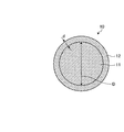
- 2 is a cross-sectional view showing a composite powder used in the method for manufacturing a composite material according to Embodiment 1.
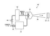
- FIG. 3 is a schematic view showing an outline of a cold spray apparatus used in the film forming step shown in FIG.
- FIG. 4 is a cross-sectional view schematically showing the structure of the composite material according to the first embodiment.
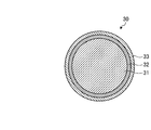
- FIG. 5 is a cross-sectional view showing the structure of the composite powder in Modification 1 of Embodiment 1.
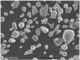
- FIG. 6 is a scanning electron micrograph of the composite powder used in the examples.
- FIG. 7 is a scanning electron micrograph of a cross section of the composite material according to the example.
- FIG. 8 is a scanning electron micrograph of a cross section in the vicinity of the interface between the composite material and the substrate according to the example.
- FIG. 1 is a flowchart showing a method for manufacturing a composite material according to Embodiment 1 of the present invention.
- step S1 a composite powder that is a raw material for the composite material is produced.
- the composite powder 10 is a powder having a particle size of, for example, about 5 to 100 ⁇ m, and includes an inner core material layer 11 and a coating layer 12 covering the periphery of the core material layer 11.
- the core material layer 11 and the covering layer 12 are formed of different types of metals or alloys.
- the composite powder 10 will be described in detail later.
- a base material on which the composite material is formed is produced.
- the material of the base material is not particularly limited as long as it is a material capable of forming a film by a cold spray method described later.
- the base material is formed of a metal or an alloy.
- the base material may be the same as or different from the metal or alloy of the core material layer 11 or the covering layer 12.
- the size and shape of the substrate are not particularly limited as long as it has a surface on which a film can be formed by the cold spray method.
- a film is formed on the substrate by a cold spray method using the composite powder 10.
- the cold spray method is a film forming method for forming a film by accelerating the raw material powder together with a gas and spraying and depositing on the surface of the base material in the solid state, for example, a cold spray shown in FIG. This is done by the device 40.
- FIG. 3 is a schematic diagram showing an outline of the cold spray device 40.
- the cold spray device 40 includes a gas heater 41 that heats the compressed gas, a powder supply device 42 that contains the composite powder 10 and supplies it to the spray gun 43, the heated compressed gas, and The gas nozzle 44 which injects the composite powder 10 supplied there toward the base material 21, and valves 45 and 46 for adjusting the supply amount of compressed gas to the gas heater 41 and the powder supply device 42, respectively.
- the compressed gas helium, nitrogen, air or the like is used.
- the compressed gas supplied to the gas heater 41 is, for example, 50 ° C. or higher, heated to a temperature in a range lower than the melting point of the coating layer 12, and then supplied to the spray gun 43.
- the heating temperature of the compressed gas is preferably 300 to 900 ° C.
- the compressed gas supplied to the powder supply device 42 supplies the composite powder in the powder supply device 42 to the spray gun 43 so that a predetermined discharge amount is obtained.
- the heated compressed gas is made a supersonic flow (about 340 m / s or more) by the gas nozzle 44 having a divergent shape.
- the gas pressure of the compressed gas is preferably about 1 to 5 MPa. This is because by adjusting the pressure of the compressed gas to this level, it is possible to improve the adhesion strength between the base material 21 and the coating film 22 formed thereon.
- These spray conditions temperature and pressure of the compressed gas, the discharge amount of the composite powder 10 and the like) are determined according to the characteristics of the coating layer 12 that is the outermost layer in direct contact with the compressed gas.
- the composite powder 10 supplied to the spray gun 43 is injected into a supersonic flow of compressed gas and accelerated to collide with the base material 21 at a high speed while maintaining at least the surface of the composite powder 10 in a solid state. To form a film 22. At this time, the composite powder 10 is also heated from the surface by the heated compressed gas, but the time from when the composite powder 10 is injected into the spray gun 43 until it is sprayed toward the base material 21 is extremely short. Therefore, the possibility that an intermetallic compound is generated inside the composite powder 10 is extremely low.
- the apparatus is limited to the cold spray apparatus 40 shown in FIG. 3 as long as the apparatus can form a film by causing the composite powder 10 to collide with the base material 21 while maintaining at least the surface of the composite powder 10 in a solid state. It is not something.
- FIG. 4 is a cross-sectional view schematically showing the structure of the coating film (composite material) 22 formed on the base material 21 by the composite material manufacturing method according to the first embodiment.
- the core material layer 11 is deposited on the base material 21 in a state where the core material layer 11 is still covered with the coating layer 12.
- the metal or alloy 23 of the core material layer 11 is filled in the network structure 24 in which the metal or alloy of the coating layer 12 is connected in a mesh shape (lattice shape or a shape in which the lattice is flattened). It has a structure.
- Such a film 22 may be used in the state of the laminated body 20 laminated on the base material 21.
- the base material 21 may be removed from the coating 22 by polishing or cutting, and the portion of the coating 22 may be used alone as a composite material.
- the composite powder 10 shown in FIG. 2 is produced by coating the periphery of a powder formed of a metal or alloy with a metal or alloy of a different type from the powder.
- a coating method well-known various methods, such as a plating method and CVD method, can be used.
- a coating method for example, a plating method
- CVD method CVD method
- the total size of the composite powder 10 is not particularly limited as long as it is a size applicable to the above-described cold spray method (about 10 to 100 ⁇ m).
- the diameter D of the core material layer 11 and the thickness d of the coating layer 12 are determined according to the composition to be realized in the coating 22. For example, if the diameter D of the core material layer 11 is 30 to 40 ⁇ m and the thickness d of the coating layer 12 is 0.7 ⁇ m, the ratio of the metal or alloy constituting the network structure 24 portion of the coating 22 is about 24 wt%. Can do. In this way, the metal composition ratio in the coating 22 can be controlled by adjusting the diameter D of the core material layer 11 and the thickness d of the coating layer 12.
- Examples of the material of the core material layer 11 and the covering layer 12 include copper, copper alloy, zinc, zinc alloy, aluminum, aluminum alloy, magnesium, magnesium alloy, nickel, nickel alloy, iron, iron alloy, titanium, titanium alloy, and chromium. Chrome alloy, niobium, niobium alloy, molybdenum, molybdenum alloy, silver, silver alloy, tin, tin alloy, tantalum, tantalum alloy, tungsten, or tungsten alloy is used.
- the combination of the types of metals or alloys constituting the core material layer 11 and the coating layer 12 is a combination in which the reactivity of the metal or alloy serving as the coating layer 12 is low compared to the metal or alloy serving as the core material layer 11.
- the reactivity of the metal or alloy is evaluated by the melting point, ionization tendency, hardness, and the like.
- a metal or alloy that is easier to melt than the covering layer 12 may be disposed in the core material layer 11. That is, among the metals or alloys constituting the composite material, the metal or alloy having the lower melting point is the core material layer 11, and the metal or alloy having the higher melting point is the coating layer 12. Specifically, when producing a composite material composed of aluminum (melting point: about 660 ° C.) and copper (melting point: about 1083 ° C.), aluminum is used as the core material layer 11 and copper is used as the coating layer in the composite powder 10. 12 is sufficient.
- the powder shape is maintained until the composite powder 10 collides with the base material 21. Can do. Therefore, the composite powder 10 can be stably ejected from the gas nozzle 44 while sufficiently heating the composite powder 10 to a temperature at which copper can be attached to the lower layer. This makes it possible to stably produce a homogeneous composite material that has sufficient adhesion and denseness with the lower layer.
- a metal or an alloy that is easier to oxidize than the covering layer 12 may be disposed on the core material layer 11. That is, of the metals constituting the composite material, the metal having the higher ionization tendency is the core material layer 11, and the metal having the smaller ionization tendency is the coating layer 12. Specifically, when producing a composite material containing aluminum and copper as components, aluminum is used as the core material layer 11 and copper is used as the coating layer 12 in the composite powder 10.
- a metal or alloy having a lower hardness than the covering layer 12 may be disposed on the core material layer 11. That is, of the metals constituting the composite material, the metal having the lower hardness is the core material layer 11, and the metal having the higher hardness is the coating layer 12.
- the metal having the lower hardness is the core material layer 11
- the metal having the higher hardness is the coating layer 12.
- the spray conditions for example, gas pressure
- the composite powder 10 can be stably ejected from the gas nozzle 44 under appropriate spray conditions.
- the composite powder in which the periphery of the core material layer 11 formed of a metal or alloy is coated with a metal or alloy that is less reactive than the core material layer 11 is used.
- the cold spray method allows normal spraying while sufficiently raising the temperature of the outer metal or alloy with low reactivity, and stable homogeneous composite materials with sufficient adhesion and denseness to the lower layer. Can be manufactured.
- the metal or alloy on the core material layer 11 side having high reactivity can be sprayed at a high temperature that does not use a composite powder, which is difficult with a normal cold spray method. Further improvement can be achieved. That is, if it is a normal powder consisting only of the metal or alloy of the core material layer 11, it is close to the melting point of the metal or alloy, so that the molten or softened metal or alloy adheres to the nozzle and cannot be sprayed. By using a composite powder, it is possible to spray in a temperature range exceeding the appropriate spray temperature range for the metal or alloy of the core layer 11. Therefore, the core material layer 11 can be sufficiently softened and a dense film can be formed.
- the manufacturing method according to the first embodiment is different from conventional manufacturing methods such as a rolling method, a sintering method, and a spraying method, or a manufacturing method in which heat treatment is performed after a film by a cold spray method, and two types adjacent to each other. Since the step of heating the metal or alloy to a high temperature (for example, higher than the melting point) is not included, the formation of intermetallic compounds can be suppressed. For this reason, it is possible to suppress deterioration in the function of the composite material such as a decrease in thermal conductivity and a decrease in mechanical strength. Therefore, it is possible to widen the combination of two kinds of metals or alloys.
- a high temperature for example, higher than the melting point
- the composite material manufactured according to the first embodiment described above has the properties of the metal or alloy of the core material layer 11 and the coating layer 12.
- a composite material in which the core material layer 11 is made of aluminum and the covering layer 12 is made of copper has lightness of aluminum, electrical characteristics (electric conductivity) and thermal characteristics (thermal conductivity) of copper, and heat close to copper. It has an expansion rate.
- this composite material has few intermetallic compounds, the original softness of the metal is maintained. Therefore, such a composite material can be applied to, for example, a heat radiating fin (a heat radiating member such as a substrate) in which aluminum is conventionally used. In this case, the thermal conductivity can be improved while utilizing the lightness of aluminum.
- the resistance value can be reduced by applying the composite material to the conductive portion where aluminum is conventionally used.
- FIG. 5 is a cross-sectional view showing the structure of the composite powder 30 in the first modification.
- a composite powder 30 shown in FIG. 5 includes a core material layer 31 and a first coating layer 32 and a second coating layer 33 formed around the core material layer 31.
- a composite powder having such a three-layer structure may be used.
- the first coating layer 32 and the second coating layer 33 are formed by sequentially coating the core material layer 31 by a plating method or the like.
- the spray conditions in the cold spray method are set according to the characteristics of the second coating layer 33 which is the outermost layer.
- the core material layer 31 is made of aluminum, a nickel layer is formed as the first coating layer 32 around it, and a copper layer is formed as the second coating layer 33.
- the formation of an intermetallic compound between aluminum and copper can be more reliably prevented by interposing nickel therebetween.
- two kinds of metals or alloys may be alternately arranged on the core material layer 31, the first coating layer 32, and the second coating layer 33.
- copper is disposed in the core material layer 31 and the second covering layer 33
- aluminum is disposed in the first covering layer 32. This makes it easy to adjust the composition ratio in the Al—Cu composite material.
- the number of coating layers formed around the core material layer 31 may be three or more. In this case, it becomes easier to achieve a desired composition ratio in the composite material, and a plurality of types of metals or alloys can be more uniformly dispersed in the composite material.
- the composite powder 10 shown in FIG. 2 (or the composite powder 30 shown in FIG. 5) is made of the same kind of metal or alloy as the outermost coating layer 12. A mixed powder obtained by mixing powder is used.
- the composition of the composite material can be controlled by adjusting the diameter D of the core material layer 11 and the thickness d of the coating layer 12.
- the thickness d of the coating layer 12 there is a limit to increasing the thickness d of the coating layer 12.
- fine adjustment of the thickness d may be difficult. Therefore, when it is desired to greatly increase the mixing ratio of the metal or alloy of the covering layer 12 or when it is desired to finely adjust the mixing ratio of the metal or alloy between the core material layer 11 and the covering layer 12, the same kind as the covering layer 12 is used.
- a mixed powder in which a powder made of the above metal or alloy is mixed with the composite powder 10.
- the composite powder in which the periphery of aluminum is coated with copper
- the same copper powder as that of the outermost layer is mixed.
- the spray conditions for example, the gas temperature
- the spray conditions are those having higher reactivity (for example, those having a lower melting point).
- metal or alloy for this reason, spray conditions are insufficient (for example, the gas temperature is too low) for a metal or alloy having a lower reactivity (for example, a higher melting point), and it becomes difficult to form a dense film.
- spray conditions are still the metal with higher reactivity. Or limited to alloys.
- the second embodiment since a composite powder obtained by coating a metal or alloy having higher reactivity (core material layer 11) with a metal or alloy having lower reactivity (coating layer 12) is used, spraying is performed.
- the cold spray method can be performed in accordance with the metal or alloy having the lower reactivity.
- the blending ratio of the metal or alloy can be easily adjusted while keeping the spray conditions in accordance with the coating layer 12. it can. Therefore, according to the second embodiment, it is possible to stably produce a homogeneous composite material that includes a plurality of different types of metals or alloys in a desired ratio and has sufficient adhesion and denseness with the lower layer. It becomes.
- Modification 2 Next, a second modification of the second embodiment will be described.
- a mixed powder obtained by mixing a general powder made of metal or an alloy and a composite powder is used.
- a cold spray using a mixed powder obtained by mixing a plurality of different composite powders is used. You may do the law.
- the type of metal or alloy forming the outermost coating layer is the same among the multiple types of composite powder, the types of metal or alloy forming the core material layer or intermediate layer thereof are different from each other. May be.
- FIG. 6 is a scanning electron microscope (SEM) photograph taken of a composite powder composed of aluminum powder and copper plating.
- the copper plating thickness was about 0.74 ⁇ m on average.
- FIG. 7 is an SEM photograph of a cross section of the film formed as described above.
- FIG. 8 is an SEM photograph of a cross section in the vicinity of the interface between the base material and the film formed thereon.
- a structure in which aluminum (Al) was filled in the copper network structure (Cu network structure) was observed in the film.
- the copper network structure (Cu network structure) and the aluminum (Al) filled therein dig into the base material due to the anchor effect, A state of being in close contact with the substrate was observed.
Landscapes
- Chemical & Material Sciences (AREA)
- Chemical Kinetics & Catalysis (AREA)
- Engineering & Computer Science (AREA)
- Materials Engineering (AREA)
- Mechanical Engineering (AREA)
- Metallurgy (AREA)
- Organic Chemistry (AREA)
- Other Surface Treatments For Metallic Materials (AREA)
Abstract
互いに異なる複数種類の金属材料からなる複合材料の製造方法であって、均質な皮膜を安定的に製造することができる複合材料の製造方法、及びこの製造方法によって製造された複合材料を提供する。複合材料の製造方法は、第1の金属又は合金によって形成された心材被覆層と、該心材被覆層を、第1の金属又は合金よりも反応性の低い第2の金属又は合金で被覆することにより形成した被覆層とを有する複合化粉末であって、被覆層が最外層をなす複合化粉末をガスと共に加速し、少なくとも複合化粉末の表面を固相状態に保ったままで基材の表面に吹き付けて堆積させることにより皮膜を形成する皮膜形成工程S3を含む。
Description
本発明は、複数種類の金属からなる複合材料の製造方法及び複合材料に関する。
従来、複数種類の金属からなる複合材料の製造方法として、圧延法、焼結法、溶射法等が知られている(例えば、特許文献1参照)。これらの圧延法、焼結法、溶射法等においては、異種の金属材料が混合又は接触配置された状態で高温(例えば融点又は軟化点以上)となる工程を含むため、金属の種類の組み合わせによっては、複合材料の機能低下の原因となる金属間化合物が形成される場合があった。
近年では、コールドスプレー法と呼ばれる皮膜形成方法により複合材料を製造することも提案されている(例えば、特許文献2参照)。ここで、コールドスプレー法とは、金属又は合金の粉末を、融点又は軟化点以下の状態の不活性ガスとともにノズルから噴射し、固相状態のまま基材に衝突させることにより、基材の表面に皮膜を形成する方法である。コールドスプレー法においては、粉末が下層(基材やそれまでに基材上に堆積した粉末)に衝突することにより、金属結合及びアンカー効果が生じて、下層との密着性及び緻密性の高い皮膜が形成される。また、コールドスプレー法においては、溶射法と比べて低い温度で工程が行われるので、金属の酸化等が抑制された皮膜を形成することができる。
上記特許文献2には、造粒又は被覆によって複数種類の金属又は合金を複合化した複合粉末を用いて上述したコールドスプレー法を行うことにより、耐熱合金皮膜を形成することが開示されている。より詳細には、特許文献2においては、コールドスプレー法における付着性が悪い材料(合金粉末)の表面に、コールドスプレー法における付着性が良い材料(純金属)を被覆等した複合粉末が用いられる。
ところで、コールドスプレー法においては、粉末と共に噴射する不活性ガスの温度や圧力(流速)といったスプレー条件を適切に設定することが重要になる。この点について、例えば上記複合粉末を用いる場合に、複合粉末の表面の材料(純金属)に合わせてスプレー条件(例えば、純金属の融点未満)を設定すると、スプレーから噴射された複合粉末が基材に衝突した際に、内側の合金粉末において十分な反応が生じず、下層との密着性や緻密性が十分でない皮膜が形成される可能性がある。反対に、複合粉末の内側の材料(合金粉末)に合わせてスプレー条件を設定すると、表面の材料が軟化して複合粉末同士が付着し、適切なスプレー条件が変わってしまったり、複合粉末がノズル内に付着してノズルが目詰まりを起こし、正常にスプレーすることができなくなるといった事態が発生し得る。このような場合、下層との密着性や緻密性を有する均質な皮膜を安定的に形成することが困難となる。
本発明は、上記に鑑みてなされたものであって、互いに異なる複数種類の金属又は合金からなる複合材料を製造する際、下層との密着性及び緻密性を十分に有する均質な複合材料を安定的に製造することができる複合材料の製造方法、及びこの製造方法によって製造された複合材料を提供することを目的とする。
上述した課題を解決し、目的を達成するために、本発明に係る複合材料の製造方法は、少なくとも、第1の金属又は合金によって形成された第1の層と、該第1の層を、前記第1の金属又は合金よりも反応性の低い第2の金属又は合金で被覆することにより形成した第2の層とを有し、該第2の層が最外層をなす複合化粉末をガスと共に加速し、少なくとも前記複合化粉末の表面を固相状態に保ったままで基材の表面に吹き付けて堆積させることにより皮膜を形成する皮膜形成工程を含むことを特徴とする。
上記複合材料の製造方法において、前記皮膜形成工程は、前記第2の金属又は合金の特性に応じて設定された条件に従って、前記複合化粉末を前記基材の表面に吹き付けることを特徴とする。
上記複合材料の製造方法において、前記第1の金属又は合金の融点は、前記第2の金属又は合金の融点よりも低いことを特徴とする。
上記複合材料の製造方法において、前記第1の金属又は合金のイオン化傾向は、前記第2の金属又は合金のイオン化傾向よりも大きいことを特徴とする。
上記複合材料の製造方法において、前記第1の金属又は合金の硬度は、前記第2の金属又は合金の硬度よりも低いことを特徴とする。
上記複合材料の製造方法において、前記第2の層は、めっき法により前記第1の層の周囲に形成されていることを特徴とする。
上記複合材料の製造方法において、前記皮膜形成工程は、前記複合化粉末に対して前記第2の金属又は合金により形成された粉末を混合した混合粉末を調製する工程を含み、該混合粉末を前記基材の表面に吹き付けることを特徴とする。
本発明に係る複合材料は、少なくとも、第1の金属又は合金によって形成された第1の層と、該第1の層を、前記第1の金属又は合金よりも反応性の低い第2の金属又は合金で被覆することにより形成した第2の層とを有し、該第2の層が最外層をなす複合化粉末をガスと共に加速し、少なくとも前記複合化粉末の表面を固相状態に保ったままで基材の表面に吹き付けて堆積させることにより形成されたことを特徴とする。
本発明に係る複合材料は、第1の金属又は合金と、該第1の金属又は合金よりも反応性の低い第2の金属又は合金とを含む複合材料であって、前記第2の金属又は合金は網目状をなす構造を有し、前記第1の金属又は合金は前記網目状をなす構造の内側に充填されていることを特徴とする。
上記複合材料において、前記第1の金属又は合金の融点は、前記第2の金属又は合金の融点よりも低いことを特徴とする。
上記複合材料において、前記第1の金属又は合金はアルミニウム又はアルミニウム合金であり、前記第2の金属又は合金は銅又は銅合金であることを特徴とする。
本発明によれば、第1の金属又は合金によって形成された第1の層と、該第1の層を第1の金属又は合金よりも反応性の低い第2の金属又は合金で被覆することにより形成した第2の層とを有し、該第2の層が最外層をなす複合化粉末を用いて、所謂コールドスプレー法より皮膜を形成するので、下層との密着性及び緻密性を十分に有する均質な複合材料を安定的に製造することが可能となる。
以下、本発明を実施するための形態を、図面を参照しながら詳細に説明する。なお、以下の実施の形態により本発明が限定されるものではない。また、以下の説明において参照する各図は、本発明の内容を理解し得る程度に形状、大きさ、及び位置関係を概略的に示してあるに過ぎない。即ち、本発明は各図で例示された形状、大きさ、及び位置関係のみに限定されるものではない。
(実施の形態1)
図1は、本発明の実施の形態1に係る複合材料の製造方法を示すフローチャートである。
まず、工程S1において、複合材料の原料となる複合化粉末を作製する。図2に示すように、複合化粉末10は、粒径が例えば5~100μm程度の粉末であり、内側の心材層11と、心材層11の周囲を覆う被覆層12とを含む。心材層11と被覆層12とは互いに異なる種類の金属又は合金によって形成されている。なお、複合化粉末10については後で詳述する。
図1は、本発明の実施の形態1に係る複合材料の製造方法を示すフローチャートである。
まず、工程S1において、複合材料の原料となる複合化粉末を作製する。図2に示すように、複合化粉末10は、粒径が例えば5~100μm程度の粉末であり、内側の心材層11と、心材層11の周囲を覆う被覆層12とを含む。心材層11と被覆層12とは互いに異なる種類の金属又は合金によって形成されている。なお、複合化粉末10については後で詳述する。
続く工程S2において、複合材料が形成される基材を作製する。基材の材料は、後述するコールドスプレー法による皮膜形成が可能な材料であれば特に限定されない。好ましくは、金属又は合金によって基材を形成すると良い。この場合、基材の材料は、心材層11又は被覆層12の金属又は合金と同種であっても良いし、異なる種類であっても良い。また、基材のサイズや形状も、コールドスプレー法による皮膜形成が可能な面を有していれば、特に限定されない。
続く工程S3において、複合化粉末10を用いたコールドスプレー法により、基材上に皮膜形成を行う。コールドスプレー法とは、原料の粉末をガスと共に加速し、固相状態のままで基材の表面に吹き付けて堆積させることにより皮膜を形成する成膜方法であり、例えば、図3に示すコールドスプレー装置40によって行われる。
図3は、コールドスプレー装置40の概要を示す模式図である。図3に示すように、コールドスプレー装置40は、圧縮ガスを加熱するガス加熱器41と、複合化粉末10を収容し、スプレーガン43に供給する粉末供給装置42と、加熱された圧縮ガス及びそこに供給された複合化粉末10を基材21に向けて噴射するガスノズル44と、ガス加熱器41及び粉末供給装置42に対する圧縮ガスの供給量をそれぞれ調節するバルブ45及び46とを備える。
圧縮ガスとしては、ヘリウム、窒素、空気などが使用される。ガス加熱器41に供給された圧縮ガスは、例えば50℃以上であって、被覆層12の融点よりも低い範囲の温度に加熱された後、スプレーガン43に供給される。圧縮ガスの加熱温度は、好ましくは300~900℃である。
一方、粉末供給装置42に供給された圧縮ガスは、粉末供給装置42内の複合化粉末をスプレーガン43に、所定の吐出量となるように供給する。
加熱された圧縮ガスは、末広形状をなすガスノズル44により超音速流(約340m/s以上)にされる。この際の圧縮ガスのガス圧力は、1~5MPa程度とすることが好ましい。圧縮ガスの圧力をこの程度に調節することにより、基材21とその上に形成される皮膜22との間の密着強度の向上を図ることができるからである。これらのスプレー条件(圧縮ガスの温度及び圧力、複合化粉末10の吐出量等)は、圧縮ガスに直接接触する最外層である被覆層12の特性に応じて決定される。
スプレーガン43に供給された複合化粉末10は、圧縮ガスの超音速流の中に投入されて加速され、少なくとも複合化粉末10の表面を固相状態に保ったまま基材21に高速で衝突して堆積し、皮膜22を形成する。この際、加熱された圧縮ガスにより複合化粉末10も表面から加熱されるが、複合化粉末10がスプレーガン43内に投入されてから基材21に向けて噴射されるまでの時間は極めて短いので、複合化粉末10の内部において金属間化合物が生成される可能性は極めて低い。
なお、複合化粉末10を基材21に、少なくとも複合化粉末10の表面を固相状態に保ったまま衝突させて皮膜を形成できる装置であれば、図3に示すコールドスプレー装置40に限定されるものではない。
図4は、実施の形態1に係る複合材料の製造方法により基材21上に形成された皮膜(複合材料)22の構造を模式的に示す断面図である。上述した複合材料の製造方法においては、心材層11が被覆層12に被覆されたままの状態で基材21上に堆積する。このため、皮膜22は、被覆層12の金属又は合金が網目状(格子状又は格子を扁平にした形状)に繋がった網目構造24の内部に、心材層11の金属又は合金23が充填された構造を有する。
このような皮膜22は、基材21上に積層された積層体20の状態で使用しても良い。或いは、皮膜22から基材21を研磨や切断等により除去し、皮膜22の部分を複合材料として単独で使用しても良い。
次に、図2に示す複合化粉末10について詳しく説明する。
複合化粉末10は、金属又は合金によって形成された粉末の周囲を、該粉末とは別種の金属又は合金で被覆することにより作製される。なお、被覆法としては、めっき法やCVD法等、公知の種々の手法を用いることができる。この際、加熱による金属間化合物の形成を抑制するため、金属又は合金の温度がなるべく上昇しない被覆方法(例えばめっき法)を用いることが好ましい。
複合化粉末10は、金属又は合金によって形成された粉末の周囲を、該粉末とは別種の金属又は合金で被覆することにより作製される。なお、被覆法としては、めっき法やCVD法等、公知の種々の手法を用いることができる。この際、加熱による金属間化合物の形成を抑制するため、金属又は合金の温度がなるべく上昇しない被覆方法(例えばめっき法)を用いることが好ましい。
複合化粉末10全体のサイズは、上述したコールドスプレー法に適用可能なサイズ(10~100μm程度)であれば特に限定されない。また、心材層11の径D及び被覆層12の厚さdは、皮膜22において実現したい組成に応じて決定される。例えば、心材層11の径Dを30~40μm、被覆層12の厚さdを0.7μmとすれば、皮膜22の網目構造24部分を構成する金属又は合金の割合を約24wt%とすることができる。このように、心材層11の径Dや被覆層12の厚さdを調節することにより、皮膜22における金属組成比を制御することができる。
心材層11及び被覆層12の材料としては、例えば、銅、銅合金、亜鉛、亜鉛合金、アルミニウム、アルミニウム合金、マグネシウム、マグネシウム合金、ニッケル、ニッケル合金、鉄、鉄合金、チタン、チタン合金、クロム、クロム合金、ニオブ、ニオブ合金、モリブデン、モリブデン合金、銀、銀合金、錫、錫合金、タンタル、タンタル合金、タングステン、又は、タングステン合金が用いられる。
心材層11及び被覆層12を構成する金属又は合金の種類の組み合わせは、心材層11となる金属又は合金と比較して、被覆層12となる金属又は合金の反応性が低い組み合わせであれば、特に限定されない。ここで、金属又は合金の反応性とは、融点や、イオン化傾向や、硬さ等によって評価される。
例えば、心材層11に、被覆層12よりも溶融し易い金属又は合金を配置しても良い。即ち、複合材料を構成する金属又は合金の内、融点の低い方の金属又は合金を心材層11とし、融点の高い方の金属又は合金を被覆層12とする。具体的には、アルミニウム(融点:約660℃)と銅(融点:約1083℃)を成分とする複合材料を製造する場合、複合化粉末10において、アルミニウムを心材層11とし、銅を被覆層12とすれば良い。
この場合、被覆層12となる銅の特性に合わせてスプレー条件(不活性ガスの温度)を決定しても、複合化粉末10が基材21に衝突するまでその粉末形状を維持しておくことができる。従って、銅を下層に付着させることが可能な温度まで複合化粉末10を十分加熱しつつ、ガスノズル44から安定的に複合化粉末10を噴射することができる。それにより、下層との密着性及び緻密性を十分に有する均質な複合材料を安定的に製造することが可能となる。
また、心材層11に、被覆層12よりも酸化し易い金属又は合金を配置しても良い。即ち、複合材料を構成する金属の内、イオン化傾向が大きい方の金属を心材層11とし、イオン化傾向が小さい方の金属を被覆層12とする。具体的には、アルミニウム及び銅を成分とする複合材料を製造する場合、複合化粉末10において、アルミニウムを心材層11とし、銅を被覆層12とする。
ここで、アルミニウム単体の粉末や、メカニカルアロイ法やアトマイズ法等によりアルミニウムと他種の金属とを複合化した粉末のように、アルミニウムが表面に露出した粉末をガスノズル44から噴射すると、表面のアルミニウムが激しく酸化するなどして、粉塵爆発が発生するおそれも考えられる。そこで、アルミニウムを例えば銅で皮膜し、アルミニウムが表面に露出しないようにすることにより、アルミニウムを成分に含む複合材料をコールドスプレー法により安全に作製することが可能になる。
また、心材層11に、被覆層12よりも硬度が低い金属又は合金を配置しても良い。即ち、複合材料を構成する金属の内、硬度が小さい方の金属を心材層11とし、硬度が高い方の金属を被覆層12とする。具体的には、銅とモリブデンを成分とする複合材料を製造する場合、複合化粉末10において、銅を心材層11とし、モリブデンを被覆層12とする。この場合、被覆層12となるモリブデンの特性に合わせてスプレー条件(例えば、ガス圧力)を決定することにより、モリブデンを下層に付着させることが可能な十分な運動エネルギーを複合化粉末10に与えつつ、その粉末形状を基材21に衝突させるまで維持しておくことができる。その結果、適切なスプレー条件の下で、ガスノズル44から安定的に複合化粉末10を噴射することが可能となる。
以上説明したように、実施の形態1によれば、金属又は合金で形成された心材層11の周囲を、該心材層11よりも反応性の低い金属又は合金で被覆した複合化粉末を用いてコールドスプレー法を行うので、反応性の低い外側の金属又は合金の温度を十分に上げつつ、正常にスプレーすることができ、下層に対する密着性及び緻密性を十分に有する均質な複合材料を安定的に製造することができる。
また、この際、反応性の高い心材層11側の金属又は合金にとっては、複合化粉末を用いない、通常のコールドスプレー法では困難な高温でスプレーすることができるので、密着性及び緻密性をさらに向上させることができる。即ち、心材層11の金属又は合金のみからなる通常の粉末であれば、当該金属又は合金の融点に近いために、溶融又は軟化した金属又は合金がノズルに付着等してスプレーできなくなる温度域でも、複合化粉末とすることで、心材層11の金属又は合金に対する適切なスプレー温度域を超えた温度域でスプレーすることが可能となる。従って、心材層11を十分に軟化させることができ、緻密な皮膜を形成することが可能となる。
また、実施の形態1に係る製造方法は、圧延法、焼結法、溶射法といった従来の製造方法、或いは、コールドスプレー法による皮膜の後で熱処理する製造方法とは異なり、互いに隣接する2種類の金属又は合金を高温(例えば融点以上)に加熱する工程を含まないので、金属間化合物の生成を抑制することができる。このため、熱伝導率の低下や機械的な強度の低下といった複合材料の機能低下を抑制することができる。従って、2種類の金属又は合金の組み合わせの幅を広げることが可能となる。
以上説明した実施の形態1により製造された複合材料は、心材層11及び被覆層12の金属又は合金の特性を兼ね備えたものとなる。例えば、心材層11をアルミニウム、被覆層12を銅で製造した複合材料は、アルミニウムの軽さと、銅の電気特性(電気伝導度)及び熱特性(熱伝導性)とを備え、銅に近い熱膨張率を有している。また、この複合材料は、金属間化合物が少ないので、金属本来の軟らかさが維持されている。従って、このような複合材料は、例えば、従来アルミニウムが用いられていた放熱フィン(基板等の放熱部材)に適用することができる。この場合、アルミニウムの軽量性を活かしつつ、熱伝導性を向上させることができる。また、従来アルミニウムが用いられていた導電部に上記複合材料を適用することにより、抵抗値を低減することも可能となる。
(変形例1)
次に、実施の形態1の変形例1について説明する。
図5は、変形例1における複合化粉末30の構造を示す断面図である。図5に示す複合化粉末30は、心材層31と、その周囲に形成された第1被覆層32及び第2被覆層33とを有する。コールドスプレー法による皮膜形成工程S3においては、このような3層構造を有する複合化粉末を用いても良い。なお、第1被覆層32及び第2被覆層33は、心材層31に対してめっき法等による被覆を順次施すことにより形成される。また、コールドスプレー法におけるスプレー条件は、最外層である第2被覆層33の特性に応じて設定される。
次に、実施の形態1の変形例1について説明する。
図5は、変形例1における複合化粉末30の構造を示す断面図である。図5に示す複合化粉末30は、心材層31と、その周囲に形成された第1被覆層32及び第2被覆層33とを有する。コールドスプレー法による皮膜形成工程S3においては、このような3層構造を有する複合化粉末を用いても良い。なお、第1被覆層32及び第2被覆層33は、心材層31に対してめっき法等による被覆を順次施すことにより形成される。また、コールドスプレー法におけるスプレー条件は、最外層である第2被覆層33の特性に応じて設定される。
具体的な構成としては、例えば、心材層31をアルミニウムで作製し、その周囲を、第1被覆層32としてニッケル層を形成し、さらに、第2被覆層33として銅層を形成する。この場合、ニッケルを間に介在させることにより、アルミニウムと銅との間における金属間化合物の生成をより確実に防止することができる。
また、心材層31、第1被覆層32、及び第2被覆層33に、2種類の金属又は合金を交互に配置しても良い。例えば、心材層31及び第2被覆層33に銅を配置し、第1被覆層32にアルミニウムを配置する。それにより、Al-Cu複合材料における組成比を調節し易くなる。
なお、心材層31の周囲に形成する被覆層の数は、3層以上としても良い。この場合、複合材料における所望の組成比をより実現し易くなると共に、複合材料において複数種類の金属又は合金をより均一に分散させることができる。
(実施の形態2)
次に、本発明の実施の形態2について説明する。
実施の形態2においては、上述した皮膜形成工程S3において、図2に示す複合化粉末10(又は図5に示す複合化粉末30)に、最外層である被覆層12と同種の金属又は合金の粉末を混合した混合粉末を用いることを特徴とする。
次に、本発明の実施の形態2について説明する。
実施の形態2においては、上述した皮膜形成工程S3において、図2に示す複合化粉末10(又は図5に示す複合化粉末30)に、最外層である被覆層12と同種の金属又は合金の粉末を混合した混合粉末を用いることを特徴とする。
ここで、上述したように、複合材料における組成は、心材層11の径D及び被覆層12の厚さdを調節することにより制御することができる。しかしながら、被覆層12の厚さdを厚くするには限界がある。また、厚さdの微調節が困難な場合もある。そこで、被覆層12の金属又は合金の配合比率を大きく増加させたい場合や、心材層11と被覆層12との間で金属又は合金の配合比率を微調節したい場合には、被覆層12と同種の金属又は合金で作製した粉末を複合化粉末10に混合した混合粉末を調製すると良い。例えば、アルミニウムの周囲を銅で被覆した複合化粉末に対しては、最外層と同じ銅の粉末を混合する。
ここで、複数種類の金属又は合金を単に混合しただけの混合粉末を用いてコールドスプレー法を行う場合、スプレー条件(例えば、ガスの温度)は、反応性が高い方(例えば、融点が低い方)の金属又は合金に合わせなくてはならない。このため、反応性が低い方(例えば、融点が高い方)の金属又は合金にとってはスプレー条件が不十分(例えば、ガスの温度が低すぎる)となり、緻密な膜を形成することが困難となる。また、複数種類の金属又は合金をボールミル等によって混合した場合においても、反応性が高い方の金属又は合金が粉末の表面に露出しているため、スプレー条件は、やはり反応性が高い方の金属又は合金に制約される。
しかしながら、実施の形態2においては、反応性が高い方の金属又は合金(心材層11)を、反応性が低い方の金属又は合金(被覆層12)で被覆した複合化粉末を用いるので、スプレー条件を反応性が低い方の金属又は合金に合わせてコールドスプレー法を行うことができる。また、この複合化粉末に対し、被覆層12と同種の金属又は合金の粉末を混合することにより、スプレー条件を被覆層12に合わせたまま、金属又は合金の配合比率を容易に調節することができる。従って、実施の形態2によれば、互いに異なる複数種類の金属又は合金を所望の比率で含み、下層との密着性及び緻密性を十分に有する均質な複合材料を安定的に製造することが可能となる。
(変形例2)
次に、実施の形態2の変形例2について説明する。
実施の形態2においては、金属又は合金からなる一般的な粉末と複合化粉末とを混合した混合粉末を用いたが、互いに異なる複数種類の複合化粉末同士を混合した混合粉末を用いてコールドスプレー法を行っても良い。この際、複数種類の複合化粉末の間で、最外層である被覆層をなす金属又は合金の種類さえ共通であれば、その内部の心材層や中間層をなす金属又は合金の種類が互いに異なっていても良い。例えば、アルミニウムの心材層を銅で被覆した複合化粉末と、ニッケルの心材層を銅で被覆した複合化粉末とを混合した混合粉末でコールドスプレー法を行うことにより、アルミニウム、ニッケル、及び銅からなる複合材料を作製することができる。このような混合粉末を用いる場合、内部の金属又は合金の種類によらず、最外層をなす共通の金属又は合金のスプレー条件を適用することができる。
次に、実施の形態2の変形例2について説明する。
実施の形態2においては、金属又は合金からなる一般的な粉末と複合化粉末とを混合した混合粉末を用いたが、互いに異なる複数種類の複合化粉末同士を混合した混合粉末を用いてコールドスプレー法を行っても良い。この際、複数種類の複合化粉末の間で、最外層である被覆層をなす金属又は合金の種類さえ共通であれば、その内部の心材層や中間層をなす金属又は合金の種類が互いに異なっていても良い。例えば、アルミニウムの心材層を銅で被覆した複合化粉末と、ニッケルの心材層を銅で被覆した複合化粉末とを混合した混合粉末でコールドスプレー法を行うことにより、アルミニウム、ニッケル、及び銅からなる複合材料を作製することができる。このような混合粉末を用いる場合、内部の金属又は合金の種類によらず、最外層をなす共通の金属又は合金のスプレー条件を適用することができる。
心材層及び被覆層の2層構造を有する複合化粉末を用いて、コールドスプレー法により皮膜を作製する実験を行った。
複合化粉末は、平均粒径が約30μmのアルミニウム粉末に対して、銅メッキを施すことにより作製した。図6は、アルミニウム粉末及び銅メッキからなる複合化粉末を撮影した走査型電子顕微鏡(SEM)写真である。なお、銅メッキの厚さは、平均で約0.74μmであった。
複合化粉末は、平均粒径が約30μmのアルミニウム粉末に対して、銅メッキを施すことにより作製した。図6は、アルミニウム粉末及び銅メッキからなる複合化粉末を撮影した走査型電子顕微鏡(SEM)写真である。なお、銅メッキの厚さは、平均で約0.74μmであった。
このような複合化粉末を用い、スプレー条件を、不活性ガス(窒素)の温度を約500℃、ガス圧力を5MPaに設定して、コールドスプレー法により、純アルミニウム(A1050)の基材上に皮膜を形成した。
図7は、上記のようにして形成された皮膜の断面を撮影したSEM写真である。また、図8は、基材とその上に形成された皮膜との界面近傍の断面を撮影したSEM写真である。図7に示すように、皮膜内においては、銅の網目構造(Cu網目構造)の内部にアルミニウム(Al)が充填された構造が観察された。また、図8に示すように、皮膜と基材との界面近傍においては、銅の網目構造(Cu網目構造)及びその内部に充填されたアルミニウム(Al)が、アンカー効果によって基材に食い込み、基材と密着している様子が観察された。
10、30 複合化粉末
11、31 心材層
12 被覆層
20 積層体
21 基材
22 皮膜(複合材料)
23 心材層の金属又は合金
24 網目構造
32 第1被覆層
33 第2被覆層
40 コールドスプレー装置
41 ガス加熱器
42 粉末供給装置
43 スプレーガン
44 ガスノズル
45、46 バルブ
11、31 心材層
12 被覆層
20 積層体
21 基材
22 皮膜(複合材料)
23 心材層の金属又は合金
24 網目構造
32 第1被覆層
33 第2被覆層
40 コールドスプレー装置
41 ガス加熱器
42 粉末供給装置
43 スプレーガン
44 ガスノズル
45、46 バルブ
Claims (11)
- 少なくとも、第1の金属又は合金によって形成された第1の層と、該第1の層を、前記第1の金属又は合金よりも反応性の低い第2の金属又は合金で被覆することにより形成した第2の層とを有し、該第2の層が最外層をなす複合化粉末をガスと共に加速し、少なくとも前記複合化粉末の表面を固相状態に保ったままで基材の表面に吹き付けて堆積させることにより皮膜を形成する皮膜形成工程を含むことを特徴とする複合材料の製造方法。
- 前記皮膜形成工程は、前記第2の金属又は合金の特性に応じて設定された条件に従って、前記複合化粉末を前記基材の表面に吹き付けることを特徴とする請求項1に記載の複合材料の製造方法。
- 前記第1の金属又は合金の融点は、前記第2の金属又は合金の融点よりも低いことを特徴とする請求項1又は2に記載の複合材料の製造方法。
- 前記第1の金属又は合金のイオン化傾向は、前記第2の金属又は合金のイオン化傾向よりも大きいことを特徴とする請求項1又は2に記載の複合材料の製造方法。
- 前記第1の金属又は合金の硬度は、前記第2の金属又は合金の硬度よりも低いことを特徴とする請求項1又は2に記載の複合材料の製造方法。
- 前記第2の層は、めっき法により前記第1の層の周囲に形成されていることを特徴とする請求項1~5のいずれか1項に記載の複合材料の製造方法。
- 前記皮膜形成工程は、前記複合化粉末に対して前記第2の金属又は合金により形成された粉末を混合した混合粉末を調製する工程を含み、該混合粉末を前記基材の表面に吹き付けることを特徴とする請求項1~6のいずれか1項に記載の複合材料の製造方法。
- 少なくとも、第1の金属又は合金によって形成された第1の層と、該第1の層を、前記第1の金属又は合金よりも反応性の低い第2の金属又は合金で被覆することにより形成した第2の層とを有し、該第2の層が最外層をなす複合化粉末をガスと共に加速し、少なくとも前記複合化粉末の表面を固相状態に保ったままで基材の表面に吹き付けて堆積させることにより形成されたことを特徴とする複合材料。
- 第1の金属又は合金と、該第1の金属又は合金よりも反応性の低い第2の金属又は合金とを含む複合材料であって、
前記第2の金属又は合金は網目状をなす構造を有し、
前記第1の金属又は合金は前記網目状をなす構造の内側に充填されていることを特徴とする複合材料。 - 前記第1の金属又は合金の融点は、前記第2の金属又は合金の融点よりも低いことを特徴とする請求項8又は9に記載の複合材料。
- 前記第1の金属又は合金はアルミニウム又はアルミニウム合金であり、前記第2の金属又は合金は銅又は銅合金であることを特徴とする請求項10に記載の複合材料。
Applications Claiming Priority (2)
| Application Number | Priority Date | Filing Date | Title |
|---|---|---|---|
| JP2011-235506 | 2011-10-26 | ||
| JP2011235506A JP5872844B2 (ja) | 2011-10-26 | 2011-10-26 | 複合材料の製造方法及び複合材料 |
Publications (1)
| Publication Number | Publication Date |
|---|---|
| WO2013061934A1 true WO2013061934A1 (ja) | 2013-05-02 |
Family
ID=48167764
Family Applications (1)
| Application Number | Title | Priority Date | Filing Date |
|---|---|---|---|
| PCT/JP2012/077269 Ceased WO2013061934A1 (ja) | 2011-10-26 | 2012-10-22 | 複合材料の製造方法及び複合材料 |
Country Status (3)
| Country | Link |
|---|---|
| JP (1) | JP5872844B2 (ja) |
| TW (1) | TWI546139B (ja) |
| WO (1) | WO2013061934A1 (ja) |
Cited By (3)
| Publication number | Priority date | Publication date | Assignee | Title |
|---|---|---|---|---|
| CN107849699A (zh) * | 2015-08-06 | 2018-03-27 | 日产自动车株式会社 | 滑动构件及其制造方法 |
| CN116623165A (zh) * | 2023-05-24 | 2023-08-22 | 西南大学 | 一种镁铝复合板的制备方法及镁铝复合板 |
| JP2024068152A (ja) * | 2022-11-04 | 2024-05-17 | ティーイー コネクティビティ ジャーマニー ゲゼルシャフト ミット ベシュレンクテル ハフツンク | スプレーコーティングを有するコンタクト要素、接続アセンブリ、スプレー媒体の使用、およびコンタクト要素を製造する方法 |
Families Citing this family (2)
| Publication number | Priority date | Publication date | Assignee | Title |
|---|---|---|---|---|
| JP6483503B2 (ja) * | 2015-03-31 | 2019-03-13 | 日本発條株式会社 | 成形加工用マグネシウム系部材 |
| JP6109281B1 (ja) * | 2015-11-26 | 2017-04-05 | 日本発條株式会社 | 積層体の製造方法 |
Citations (4)
| Publication number | Priority date | Publication date | Assignee | Title |
|---|---|---|---|---|
| JPH08311502A (ja) * | 1995-05-15 | 1996-11-26 | Mitsubishi Materials Corp | 溶射用複合粉末 |
| JP2010095790A (ja) * | 2008-09-19 | 2010-04-30 | Nikon Corp | 成膜方法、この成膜方法により製造された固体材料の膜および複合構造物、成膜用の噴射加工装置、並びにリチウムイオン電池の負極材料 |
| JP2010185135A (ja) * | 2009-01-14 | 2010-08-26 | Kyushu Univ | コアシェル型金属ナノ粒子の製造方法 |
| JP2011204753A (ja) * | 2010-03-24 | 2011-10-13 | Sanyo Electric Co Ltd | コンデンサ用電極体の製造方法およびコンデンサの製造方法 |
Family Cites Families (2)
| Publication number | Priority date | Publication date | Assignee | Title |
|---|---|---|---|---|
| JP5500676B2 (ja) * | 2009-12-24 | 2014-05-21 | 株式会社日立製作所 | 耐熱合金皮膜の形成方法、それに用いる複合粉末 |
| JP2011208165A (ja) * | 2010-03-27 | 2011-10-20 | Iwate Industrial Research Center | コールドスプレー用皮膜材料及びその製造方法 |
-
2011
- 2011-10-26 JP JP2011235506A patent/JP5872844B2/ja active Active
-
2012
- 2012-10-22 WO PCT/JP2012/077269 patent/WO2013061934A1/ja not_active Ceased
- 2012-10-25 TW TW101139435A patent/TWI546139B/zh active
Patent Citations (4)
| Publication number | Priority date | Publication date | Assignee | Title |
|---|---|---|---|---|
| JPH08311502A (ja) * | 1995-05-15 | 1996-11-26 | Mitsubishi Materials Corp | 溶射用複合粉末 |
| JP2010095790A (ja) * | 2008-09-19 | 2010-04-30 | Nikon Corp | 成膜方法、この成膜方法により製造された固体材料の膜および複合構造物、成膜用の噴射加工装置、並びにリチウムイオン電池の負極材料 |
| JP2010185135A (ja) * | 2009-01-14 | 2010-08-26 | Kyushu Univ | コアシェル型金属ナノ粒子の製造方法 |
| JP2011204753A (ja) * | 2010-03-24 | 2011-10-13 | Sanyo Electric Co Ltd | コンデンサ用電極体の製造方法およびコンデンサの製造方法 |
Cited By (3)
| Publication number | Priority date | Publication date | Assignee | Title |
|---|---|---|---|---|
| CN107849699A (zh) * | 2015-08-06 | 2018-03-27 | 日产自动车株式会社 | 滑动构件及其制造方法 |
| JP2024068152A (ja) * | 2022-11-04 | 2024-05-17 | ティーイー コネクティビティ ジャーマニー ゲゼルシャフト ミット ベシュレンクテル ハフツンク | スプレーコーティングを有するコンタクト要素、接続アセンブリ、スプレー媒体の使用、およびコンタクト要素を製造する方法 |
| CN116623165A (zh) * | 2023-05-24 | 2023-08-22 | 西南大学 | 一种镁铝复合板的制备方法及镁铝复合板 |
Also Published As
| Publication number | Publication date |
|---|---|
| JP2013091832A (ja) | 2013-05-16 |
| TW201323117A (zh) | 2013-06-16 |
| JP5872844B2 (ja) | 2016-03-01 |
| TWI546139B (zh) | 2016-08-21 |
Similar Documents
| Publication | Publication Date | Title |
|---|---|---|
| JP5730089B2 (ja) | 導電材料、積層体および導電材料の製造方法 | |
| US8591986B1 (en) | Cold spray deposition method | |
| JP5809901B2 (ja) | 積層体及び積層体の製造方法 | |
| JP5745315B2 (ja) | 積層体および積層体の製造方法 | |
| JP5826283B2 (ja) | ターゲットアセンブリの製造方法 | |
| JP5872844B2 (ja) | 複合材料の製造方法及び複合材料 | |
| CN108315686B (zh) | 一种伪高熵合金涂层配方及其涂层制备方法 | |
| CN101063203B (zh) | 带镀层金属板的制造方法 | |
| KR20050081252A (ko) | 다공성 금속 코팅 부재 및 저온 분사법을 이용한 그의제조 방법 | |
| JPS5993864A (ja) | 高能率沸騰熱伝達構造体及びその製造方法 | |
| JP6644147B2 (ja) | 鋼板の金属コーティング方法及びそれを用いて製造された金属コーティング鋼板 | |
| JP3946226B2 (ja) | 金属ガラス積層体、およびその製造方法 | |
| JPH10302624A (ja) | X線管陽極の製造方法 | |
| JP4644653B2 (ja) | 金属ガラス積層体 | |
| CN113088960B (zh) | 一种钛合金软包装耐磨涂层及其制备方法 | |
| CN108296602A (zh) | 一种金属基材功能件及其增材加工制备方法 | |
| CN111151741B (zh) | 包浆法间接金属3d打印生坯钎涂和/或熔结后处理改性方法 | |
| JP5548948B2 (ja) | 薄板金属基材上に金属ガラス溶射被膜層が形成された複合材料及びその製造方法 | |
| CN116024517B (zh) | 耐蚀材料及其制备方法和应用 | |
| CN116254497A (zh) | 一种制备高氧化铝含量Al基复合涂层的无缝粉芯丝材及其制备方法 | |
| KR102741009B1 (ko) | 코팅체 및 코팅체 제조방법 | |
| CN109518117A (zh) | 一种应用于等离子喷涂的金属粉末 | |
| CN102245332A (zh) | 用于制备经烧结的金属构件的前体、制备所述前体的方法以及所述构件的制备方法 | |
| US20240084457A1 (en) | Expansive coatings for anchoring to composite substrates | |
| KR102083075B1 (ko) | 합금 박막 및 그 제조 방법 |
Legal Events
| Date | Code | Title | Description |
|---|---|---|---|
| 121 | Ep: the epo has been informed by wipo that ep was designated in this application |
Ref document number: 12844008 Country of ref document: EP Kind code of ref document: A1 |
|
| NENP | Non-entry into the national phase |
Ref country code: DE |
|
| 122 | Ep: pct application non-entry in european phase |
Ref document number: 12844008 Country of ref document: EP Kind code of ref document: A1 |