WO2013061769A1 - ガスエンジンならびにガスエンジンを利用したガスヒートポンプ装置およびコージェネレーション装置 - Google Patents
ガスエンジンならびにガスエンジンを利用したガスヒートポンプ装置およびコージェネレーション装置 Download PDFInfo
- Publication number
- WO2013061769A1 WO2013061769A1 PCT/JP2012/076121 JP2012076121W WO2013061769A1 WO 2013061769 A1 WO2013061769 A1 WO 2013061769A1 JP 2012076121 W JP2012076121 W JP 2012076121W WO 2013061769 A1 WO2013061769 A1 WO 2013061769A1
- Authority
- WO
- WIPO (PCT)
- Prior art keywords
- gas engine
- switching
- stoichiometric
- valve
- lean
- Prior art date
- Legal status (The legal status is an assumption and is not a legal conclusion. Google has not performed a legal analysis and makes no representation as to the accuracy of the status listed.)
- Ceased
Links
Images


Classifications
-
- F—MECHANICAL ENGINEERING; LIGHTING; HEATING; WEAPONS; BLASTING
- F02—COMBUSTION ENGINES; HOT-GAS OR COMBUSTION-PRODUCT ENGINE PLANTS
- F02D—CONTROLLING COMBUSTION ENGINES
- F02D41/00—Electrical control of supply of combustible mixture or its constituents
- F02D41/0025—Controlling engines characterised by use of non-liquid fuels, pluralities of fuels, or non-fuel substances added to the combustible mixtures
- F02D41/0027—Controlling engines characterised by use of non-liquid fuels, pluralities of fuels, or non-fuel substances added to the combustible mixtures the fuel being gaseous
-
- F—MECHANICAL ENGINEERING; LIGHTING; HEATING; WEAPONS; BLASTING
- F02—COMBUSTION ENGINES; HOT-GAS OR COMBUSTION-PRODUCT ENGINE PLANTS
- F02D—CONTROLLING COMBUSTION ENGINES
- F02D19/00—Controlling engines characterised by their use of non-liquid fuels, pluralities of fuels, or non-fuel substances added to the combustible mixtures
- F02D19/02—Controlling engines characterised by their use of non-liquid fuels, pluralities of fuels, or non-fuel substances added to the combustible mixtures peculiar to engines working with gaseous fuels
- F02D19/021—Control of components of the fuel supply system
- F02D19/022—Control of components of the fuel supply system to adjust the fuel pressure, temperature or composition
-
- F—MECHANICAL ENGINEERING; LIGHTING; HEATING; WEAPONS; BLASTING
- F02—COMBUSTION ENGINES; HOT-GAS OR COMBUSTION-PRODUCT ENGINE PLANTS
- F02D—CONTROLLING COMBUSTION ENGINES
- F02D2250/00—Engine control related to specific problems or objectives
- F02D2250/36—Control for minimising NOx emissions
-
- F—MECHANICAL ENGINEERING; LIGHTING; HEATING; WEAPONS; BLASTING
- F02—COMBUSTION ENGINES; HOT-GAS OR COMBUSTION-PRODUCT ENGINE PLANTS
- F02D—CONTROLLING COMBUSTION ENGINES
- F02D41/00—Electrical control of supply of combustible mixture or its constituents
- F02D41/30—Controlling fuel injection
- F02D41/3011—Controlling fuel injection according to or using specific or several modes of combustion
- F02D41/3064—Controlling fuel injection according to or using specific or several modes of combustion with special control during transition between modes
-
- Y—GENERAL TAGGING OF NEW TECHNOLOGICAL DEVELOPMENTS; GENERAL TAGGING OF CROSS-SECTIONAL TECHNOLOGIES SPANNING OVER SEVERAL SECTIONS OF THE IPC; TECHNICAL SUBJECTS COVERED BY FORMER USPC CROSS-REFERENCE ART COLLECTIONS [XRACs] AND DIGESTS
- Y02—TECHNOLOGIES OR APPLICATIONS FOR MITIGATION OR ADAPTATION AGAINST CLIMATE CHANGE
- Y02E—REDUCTION OF GREENHOUSE GAS [GHG] EMISSIONS, RELATED TO ENERGY GENERATION, TRANSMISSION OR DISTRIBUTION
- Y02E20/00—Combustion technologies with mitigation potential
- Y02E20/14—Combined heat and power generation [CHP]
Definitions
- the present invention relates to a gas engine and a gas heat pump device and a cogeneration device using the gas engine.
- Gas engines are known as driving sources for gas heat pump devices and cogeneration devices.
- the present invention provides a gas engine capable of smoothly switching between stoichiometric operation and lean operation, and a gas heat pump device and a cogeneration device using the gas engine.
- the gas engine of the present invention for solving the above problems is a gas engine that performs stoichiometric operation when the engine is high load and lean operation when the engine is low and medium, and supplies a mixture of air and fuel gas to the gas engine
- the valve has a certain opening area that realizes the excess air ratio in stoichiometric operation, and when switching from stoichiometric operation to lean operation, the opening area is uniform over time until the switching operation ends.
- the excess air ratio decreases and the excess air ratio of lean operation increases, a certain opening area is secured to realize the lean air excess ratio, and when switching from lean operation to stoichiometric operation, time elapses until the switching operation ends At the same time, the opening area is controlled so that the opening area increases uniformly and the excess air ratio decreases.
- the valve is composed of one proportional control valve in which three different proportional control regions in which the valve opening and the valve opening area are proportional to each other at a constant value.
- a large stoichiometric operation region, a lean operation region with a small opening degree, and an intermediate switching operation region may be used.
- the operating time of the switching operation can be set so that the engine speed fluctuation range is not more than a predetermined threshold. Also good.
- a gas heat pump device of the present invention for solving the above-described problems has the above gas engine.
- the cogeneration apparatus of the present invention for solving the above-described problems has the gas engine.
- a gas engine control method for solving the above-mentioned problems is a gas engine that performs stoichiometric operation when the engine is high load and lean operation when the engine is low and medium load, and is a mixture of air and fuel gas in the gas engine.
- the valve that secures a certain opening area that realizes the excess air ratio of the stoichiometric operation, and when switching from the stoichiometric operation to the lean operation, the switching operation is completed.
- the opening area is reduced uniformly to increase the excess air ratio, and during lean operation, a certain opening area is ensured to achieve the excess air ratio of the lean operation.
- the switching operation until the switching operation ends, increase the opening area uniformly over time and decrease the excess air ratio. And it performs mouth area control.
- stoichiometric operation can be performed when high load is required, and lean operation can be performed at medium and low load, so the range of load that can be handled is expanded, so various equipment devices such as gas heat pump devices and cogeneration devices When this gas engine is used, it is possible to use an optimal gas engine even with a small displacement, thereby reducing costs and saving energy.
- the engine can be designed compactly.
- the gas heat pump device using such a gas engine can improve the energy consumption efficiency (APF) throughout the year, and the overall energy efficiency of the cogeneration device can also be improved.
- APF energy consumption efficiency
- 4 is a graph showing a relationship between a valve opening and a valve opening area and a relationship between a valve opening and an excess air ratio when the gas engine according to the present invention shifts from lean operation to stoichiometric operation. It is a graph which shows the relationship between the control time at the time of shifting to the stoichiometric operation from the lean operation of the gas engine which concerns on this invention, and a valve opening degree. It is a graph which shows the relationship between the transition time at the time of shifting to the stoichiometric operation from the lean operation of the gas engine which concerns on this invention, and rotation speed fluctuation
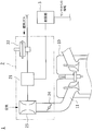
- FIG. 1 is a block diagram showing an outline of the overall configuration of the gas engine 1
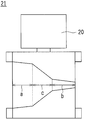
- FIG. 2 shows a proportional control valve 21 of the gas engine 1
- FIG. 3 shows between the lean operation and the stoichiometric operation by the gas engine 1.
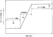
- 4 shows the relationship between the valve opening area and the valve opening when switching, and FIG. 4 shows the relationship between the valve opening and time when switching between lean operation and stoichiometric operation by the gas engine 1.
- This gas engine 1 is a gas engine 1 that performs stoichiometric operation at high loads and leans at medium and low loads, and has three proportional control areas with different stoichiometric operation areas a, lean operation areas b, and switching operation areas c.
- One valve 21 is provided.
- the valve 21 is connected between the regulator 22 and the mixer 23 to constitute the fuel supply device 2.
- each proportional control region includes a stoichiometric operation region a having a large opening, a lean operation region b having a small opening, and a switching operation region c in the middle.
- the control motor 20 controls the valve opening. It is configured.
- the lean operation region b is within the range of the opening 0-30 of the opening 0-100% of the valve 21, more preferably within the range of the opening 0-40.
- a region in which the opening area of the valve 21 is proportional to a constant value is formed in accordance with the opening degree of the valve 21.
- the opening area through which the fuel gas passes can be adjusted according to the opening degree of the valve 21. That is, as shown in FIG. 3, the switching operation region c is a range of the opening 70 to 30 between the stoichiometric operation region a and the lean operation region b out of the opening 0-100% of the valve 21.
- an area in which the opening area of the valve 21 is proportional to the opening degree of the valve 21 is formed in a range of opening degrees 60 to 40 in accordance with the opening degree of the valve 21.
- ⁇ the range of air excess ratio at which lean combustion is performed
- the regulator 22 controls the pressure of the fuel gas so that the fuel gas can be always supplied at a constant pressure.
- the mixer 23 is configured by a Venturi tube that mixes fuel gas and air.
- the mixer 23 is configured to mix fuel gas and air by the venturi effect of the air sucked according to the opening degree of the throttle valve 24 provided on the downstream side.
- the fuel supply device 2 configured as described above is connected to the intake port 11 of the cylinder head 10 of the gas engine 1.
- the gas engine 1 is provided with a sensor (not shown) for measuring the oxygen concentration in the exhaust gas in the exhaust passage or the like, and measures the excess air ratio based on the measurement detection result. .
- the gas engine 1 can smoothly switch between the stoichiometric operation and the lean operation by controlling the fuel supply device 2 and the like by the control unit 3 based on the measurement detection result by the sensor and the like. Further, in the stoichiometric operation, although concentration of NO X in the exhaust gas becomes high, is the reduction treatment by providing a three-way catalyst in an exhaust passage.
- stoichiometric operation is performed in an operating environment that requires high output.
- the opening of the valve 21 is increased, the opening area is increased and the fuel gas concentration is increased. That is, the excess air ratio is decreased.
- the opening is decreased, the opening area is decreased and the fuel gas concentration is decreased. The rate goes up.
- the switching operation region c of the valve 21 is formed with a region in which the opening area of the valve 21 is proportional to the opening of the valve 21 so as to be suitable for the switching operation.
- lean operation is performed.
- the opening of the valve 21 is lowered, the opening area is reduced and the fuel gas concentration is decreased, that is, the excess air ratio is increased, and when the opening is increased, the opening area is increased and the fuel gas concentration is increased, that is, the air is excessive. The rate goes down.
- valve opening The relationship between the valve opening and the control time is as shown in FIG. That is, in the stoichiometric operation region a and the lean operation region b, control is performed so as to maintain a predetermined excess air ratio by a predetermined valve opening, so the control time ta and the lean operation region b in the stoichiometric operation region a are controlled.
- the valve opening does not change much with respect to the control time tb at
- the control time tc in the switching operation region c changes from the stoichiometric operation to the lean operation by greatly changing the valve opening over a time period equal to or less than the above threshold A. Change to driving or vice versa.
- the control is performed using the stoichiometric operation region a formed in the valve 21 to perform lean combustion.
- the valve 21 makes it possible to achieve both lean operation, stoichiometric operation, and switching operation between them.
- the gas engine 1 thus configured can be suitably used as a drive source for a gas heat pump device (not shown).
- the gas heat pump device is required to have a high load in winter and summer, but can sufficiently cope with a medium and low load in the spring and autumn seasons.
- the gas engine 1 drives a plurality of compressors when a high load is required, and conversely, when the load is low, it is normal to drive a single compressor. Therefore, the gas heat pump device using the gas engine 1 can perform lean operation when the load is medium and low, and can switch to the stoichiometric operation when high load is required. The cost can be reduced by using the gas engine 1 having the displacement.
- the stoichiometric operation reduces the thermal efficiency, but driving multiple compressors increases the mechanical efficiency, so the thermal efficiency is equivalent to the lean operation at medium and low loads.
- the thermal efficiency at the time of medium and low loads is excellent because the lean operation is performed. Therefore, it is possible to increase the efficiency of year-round energy consumption efficiency (APF).
- the fuel supply device 2 that performs the stoichiometric operation to the lean operation can be configured by the single valve 21, not only the gas engine 1 itself can be reduced but also the entire gas engine 1 can be reduced in size. it can.
- the gas engine 1 can also be suitably used as a drive source for a cogeneration device (not shown). That is, the cogeneration apparatus can achieve energy saving by performing a stoichiometric operation when performing a lean operation during normal operation and switching to a heat main operation with a high load.
- the gas engine according to the present invention is used as a drive source for various energy saving facilities.
Landscapes
- Engineering & Computer Science (AREA)
- Chemical & Material Sciences (AREA)
- Combustion & Propulsion (AREA)
- Mechanical Engineering (AREA)
- General Engineering & Computer Science (AREA)
- Output Control And Ontrol Of Special Type Engine (AREA)
- Electrical Control Of Air Or Fuel Supplied To Internal-Combustion Engine (AREA)
Abstract
ストイキ運転とリーン運転との切り替えをスムーズに行えるガスエンジン、それを利用したガスヒートポンプ装置およびコージェネレーション装置、ならびにガスエンジンの制御方法を提供する。高負荷時にはストイキ運転し、中低負荷時にはリーン運転するガスエンジン(1)であって、ガスエンジン(1)に空気と燃料ガスとの混合気を供給するバルブ(21)は、ストイキ運転、ストイキ運転からリーン運転への切り替え、リーン運転、リーン運転からストイキ運転への切り替えができるように、一つの比例制御弁に、開度が小さいストイキ運転領域aと、開度が大きいリーン運転領域bと、その中間の切替運転領域cとが形成されたものである。
Description
本発明は、ガスエンジンと、それを利用したガスヒートポンプ装置およびコージェネレーション装置に関するものである。
ガスヒートポンプ装置およびコージェネレーション装置の駆動源として、ガスエンジンが知られている。
従来より、このようなガスエンジンとしては、ストイキ運転とリーン運転とを切り替えるようになされたものが開示されている(例えば、特許文献1参照)。
しかし、上記従来のガスエンジンのように、ストイキ運転とリーン運転とを切り替える場合、ストイキ運転において制御すべき理論空燃比の空気過剰率(λ=1)に対して、リーン運転において制御すべき空気過剰率(λ=1.4~1.6)は、制御領域に幅があり、両者の制御精度が大きく異なるため、リーン運転用の空燃比制御バルブでは、リーン運転からストイキ運転まで移行できたとしても、ストイキ運転において、理論空燃比の空気過剰率(λ=1)を制御することができなかった。
そのため、ストイキ運転用に設定した空燃比制御バルブを用いることが考えられるが、この場合は、ストイキ運転用に制御精度を設定しているので、リーン運転の領域まで空気過剰率を上げることはできなかった。
また、ストイキ運転用の空燃比制御バルブとリーン運転用の空燃比制御バルブとの間の切り替えによって両運転をカバーすることが考えられるが、両バルブの制御精度が大きく異なるため、切り替え過程において、スムーズな移行ができない。特にガスエンジンの場合、ストイキ運転からリーン運転に移行する途中に、排気ガス中のNOXの発生量が多くなる空気過剰率の領域(λ=1~1.3)があるため、ストイキ運転とリーン運転との間のスムーズな移行ができなければ、一時的に排気ガス中のNOXが高くなったり、ガスエンジンの回転数の変動が高くなったりするといった不都合を生じることとなる。
本発明は、ストイキ運転とリーン運転との切り替えをスムーズに行うことができるガスエンジンと、それを利用したガスヒートポンプ装置およびコージェネレーション装置を提供する。
上記課題を解決するための本発明のガスエンジンは、エンジンの高負荷時にはストイキ運転し、中低負荷時にはリーン運転するガスエンジンであって、ガスエンジンに空気と燃料ガスとの混合気を供給するバルブは、ストイキ運転の空気過剰率を実現する一定の開口面積が確保され、ストイキ運転からリーン運転に切り替える際には、切替運転を終了するまでの間、時間の経過とともに一様に開口面積が減少して空気過剰率が上昇し、リーン運転の空気過剰率を実現する一定の開口面積が確保され、リーン運転からストイキ運転に切り替える際には、切替運転を終了するまでの間、時間の経過とともに開口面積が一様に増加して空気過剰率が減少する、ように開口面積制御が行われるものである。
上記ガスエンジンにおいて、バルブは、バルブ開度とバルブ開口面積とが一定値で比例する異なった3つの比例制御領域が形成された一つの比例制御弁からなり、各比例制御領域は、開度が大きいストイキ運転領域と、開度が小さいリーン運転領域と、その中間の切替運転領域となされたものであってもよい。
切替運転の運転時間と、それに伴うエンジンの回転変動幅との関係から、エンジンの回転変動幅が、所定の閾値以下となるように切替運転の運転時間を設定できるようになされたものであってもよい。
また、上記課題を解決するための本発明のガスヒートポンプ装置は、上記のガスエンジンを有するものである。
さらに、上記課題を解決するための本発明のコージェネレーション装置は、上記ガスエンジンを有するものである。
さらに、上記課題を解決するための本発明のガスエンジンの制御方法は、エンジンの高負荷時にはストイキ運転し、中低負荷時にはリーン運転するガスエンジンにおいて、ガスエンジンに空気と燃料ガスとの混合気を供給するバルブは、ストイキ運転の際には、当該ストイキ運転の空気過剰率を実現する一定の開口面積を確保し、ストイキ運転からリーン運転に切り替える際には、切替運転を終了するまでの間、時間の経過とともに一様に開口面積を減少させて空気過剰率を上昇させ、リーン運転の際には、当該リーン運転の空気過剰率を実現する一定の開口面積を確保し、リーン運転からストイキ運転に切り替える際には、切替運転を終了するまでの間、時間の経過とともに開口面積を一様に増加させて空気過剰率を減少させる、ように開口面積制御を行うものである。
以上述べたように、本発明によると、一時的に排気ガス中のNOXが高くなったり、ガスエンジンの回転数の変動が高くなったりすることを防止することができる。
また、高負荷が必要な場合にはストイキ運転を行い、中低負荷時はリーン運転を行うことができ、対応可能な負荷の範囲が広がるので、ガスヒートポンプ装置やコージェネレーション装置などの各種設備装置にこのガスエンジンを使用する場合、小排気量であっても最適なガスエンジンを使用することが可能となり、コストの低減および省エネルギーを図ることができる。
さらに、複数のバルブを使用することなく、1つのバルブによってストイキ運転、リーン運転、切替運転を行うことができるので、エンジンをコンパクトに設計することができる。
したがって、このようなガスエンジンを使用したガスヒートポンプ装置は通年エネルギー消費効率(APF)の向上を図ることができるとともに、コージェネレーション装置についても総合的なエネルギー効率の向上を図ることができる。
以下、本発明の実施の形態を図面を参照して説明する。
図1はガスエンジン1の全体構成の概略を示すブロック図を示し、図2は同ガスエンジン1の比例制御バルブ21を示し、図3は同ガスエンジン1によりリーン運転とストイキ運転との間を切り替える際のバルブ開口面積とバルブ開度との関係を示し、図4は同ガスエンジン1によりリーン運転とストイキ運転との間を切り替える際のバルブ開度と時間との関係を示している。
このガスエンジン1は、高負荷時にはストイキ運転し、中低負荷時にはリーン運転するガスエンジン1であって、ストイキ運転領域a、リーン運転領域b、切替運転領域cの異なった3つの比例制御領域を有する一つのバルブ21を有している。
このバルブ21は、レギュレータ22とミキサー23との間に接続されて燃料供給装置2を構成している。
バルブ21は、バルブ開度とバルブ開口面積とが一定値で比例する異なった3つの比例制御領域が一つの比例制御弁に形成されている。各比例制御領域は、開度が大きいストイキ運転領域aと、開度が小さいリーン運転領域bと、その中間の切替運転領域cとからなり、制御モータ20によってバルブ開度の制御を行うように構成されている。
ストイキ運転領域aは、理論空燃比となる空気過剰率(λ=1)をピンポイントで制御するために、バルブ開度に合わせて燃料ガスが通過する開口面積を調整できるように設計されている。すなわち、このストイキ運転領域aは、図3に示すように、バルブ21の開度0-100%のうちの開度80~100の範囲、さらに好ましくは開度70~100の範囲に、当該バルブ21の開度に合わせてバルブ21の開口面積が一定値で比例する領域を形成して構成されている。ストイキ運転領域aは、上記したバルブ開度の範囲で、理論空燃比となる空気過剰率(λ=1)を制御することができる流量特性のものであれば特に限定されるものでは無いが、ガスエンジン1を使用する環境雰囲気温度やガスエンジン1の使用回転数域の変化に対応する必要があるため、これらの変化に追従して理論空燃比となる空気過剰率(λ=1)を制御可能な流量特性を有するように比例制御領域を形成したものが使用される。
リーン運転領域bは、リーン燃焼となる空気過剰率の範囲(λ=1.4~1.6)を制御するために、バルブ21の開度に合わせて燃料ガスが通過する開口面積を調整できるように設計されている。すなわち、このリーン運転領域bは、図3に示すように、バルブ21の開度0-100%のうちの開度0~30の範囲、さらに好ましくは開度0~40の範囲に、当該バルブ21の開度に合わせてバルブ21の開口面積が一定値で比例する領域を形成して構成されている。リーン運転領域bは、上記したバルブ開度の範囲で、リーン燃焼となる空気過剰率の範囲(λ=1.4~1.6)を制御できる流量特性のものであれば特に限定されるものでは無いが、ガスエンジン1を使用する環境雰囲気温度やガスエンジン1の使用回転数域の変化に対応する必要があるため、これらの変化に追従してリーン燃焼となる空気過剰率の範囲(λ=1.4~1.6)を制御可能な流量特性を有するように比例制御領域を形成したものが使用される。
切替運転領域cは、上記した理論空燃比となる空気過剰率(λ=1)から、リーン燃焼となる空気過剰率の範囲(λ=1.4~1.6)への切替を制御するために、バルブ21の開度に合わせて燃料ガスが通過する開口面積を調整できるように設計されている。すなわち、この切替運転領域cは、図3に示すように、バルブ21の開度0-100%のうち、上記ストイキ運転領域aとリーン運転領域bとの間の開度70~30の範囲、好ましくは開度60~40の範囲に、当該バルブ21の開度に合わせてバルブ21の開口面積が一定値で比例する領域を形成して構成されている。切替運転領域cは、上記したバルブ開度の範囲で、理論空燃比となる空気過剰率(λ=1)から、リーン燃焼となる空気過剰率の範囲(λ=1.4~1.6)への切替を制御できる流量特性のものであれば特に限定されるものでは無いが、ガスエンジン1を使用する環境雰囲気温度やガスエンジン1の使用回転数域の変化に対応する必要があるため、これらの変化に追従して理論空燃比となる空気過剰率(λ=1)から、リーン燃焼となる空気過剰率の範囲(λ=1.4~1.6)への切替を制御可能な流量特性を有するように比例制御領域を形成したものが使用される。
レギュレータ22は、常に一定の圧力で燃料ガスを供給できるように、燃料ガスの圧力を制御するようになされている。
ミキサー23は、燃料ガスと空気とを混合するベンチュリ管によって構成されている。このミキサー23は、下流側に設けられたスロットル弁24の開度に応じて吸入される空気のベンチュリ効果で燃料ガスと空気とを混合するようになされている。
上記構成の燃料供給装置2は、ガスエンジン1のシリッダヘッド10の吸気口11に接続される。このガスエンジン1には、排ガス中の酸素濃度などを測定するセンサ(図示省略)が、排気経路などに設けられており、この測定検出結果に基づいて空気過剰率を測定するようになされている。ガスエンジン1は、制御部3により、このセンサ等による測定検出結果に基づいて燃料供給装置2等の制御を行うことで、ストイキ運転とリーン運転とをスムーズに切り替えることができる。また、ストイキ運転では、排気ガス中のNOX濃度が高くなるが、排気経路に三元触媒を設けて還元処理される。
次に、制御部3によるこのガスエンジン1の制御について説明する。
まず、高出力を必要とする運転環境の場合、ストイキ運転が行われる。このストイキ運転は、理論空燃比の空気過剰率(λ=1)となるように、バルブ21の開度をストイキ運転領域aで制御して行われる。バルブ21は、開度を上げれば開口面積が増えて燃料ガス濃度が濃くなる、すなわち、空気過剰率が下がり、開度を下げれば開口面積が減って燃料ガス濃度が薄くなる、すなわち、空気過剰率が上がる。この際、バルブ21のストイキ運転領域aは、理論空燃比の空気過剰率(λ=1)を制御し易いように、バルブ21の開度に合わせてバルブ21の開口面積が一定値で比例する領域を形成しているので、理論空燃比の空気過剰率(λ=1)を容易に制御することができる。
上記ストイキ運転から、高出力の必要が無い中低負荷の運転環境になった場合は、ストイキ運転から空気過剰率λ=1.4~1.6のリーン運転へと切り替える。
この切り替えを行うには、バルブ21の開度を切替運転領域cで制御して行われる。この際、バルブ21は、開度を下げれば開口面積が減って燃料ガス濃度が薄くなる、すなわち、空気過剰率が上がり、ストイキ運転となる理論空燃比の空気過剰率(λ=1)から、リーン燃焼となる空気過剰率の範囲(λ=1.4~1.6)へと移行する。
なお、この切替運転の際、排気ガス中のNOXの発生量が多くなる空気過剰率領域(λ=1~1.3)をできるだけ早く通過したい。しかし、早く通過すると、図5に示すように、回転数変動を生じてガスエンジン1とその被駆動物を傷めてしまうこととなる。本願発明の場合は、この移行時間については、切替運転領域cにおいてバルブ21の開度の制御時間を自由に設定できるので、ガスエンジン1等を傷めることの無いように、ガスエンジン1の回転変動が所定の閾値A以下となる切替時間をかけて行うことができる。しかも、バルブ21の切替運転領域cには、切替運転に適するように、バルブ21の開度に合わせてバルブ21の開口面積が一定値で比例する領域を形成しているので、このバルブ21の開度を制御することによって排気ガス中のNOXの発生量が多くなる空気過剰率領域(λ=1~1.3)をスムーズに通過して運転切替を行うことができることとなり、排気ガス中のNOXの発生量を最低限に抑えることができる。
このようにしてリーン運転に切り替わった後は、リーン運転が行われる。このリーン運転は、リーン燃焼の空気過剰率の範囲(λ=1.4~1.6)となるように、バルブ21の開度をリーン運転領域bで制御して行われる。バルブ21は、開度を下げれば開口面積が減って燃料ガス濃度が薄くなる、すなわち、空気過剰率が上がり、開度を上げれば開口面積が増えて燃料ガス濃度が濃くなる、すなわち、空気過剰率が下がる。この際、バルブ21のリーン運転領域bは、リーン燃焼の空気過剰率の範囲(λ=1.4~1.6)を制御し易いように、バルブ21の開度に合わせてバルブ21の開口面積が一定値で比例する領域を形成しているので、リーン燃焼の空気過剰率の範囲(λ=1.4~1.6)を容易に制御することができる。
上記リーン運転から、高出力が必要な運転環境になった場合は、空気過剰率λ=1.4~1.6のリーン運転から、再度、バルブ21の切替運転領域cを利用して理論空燃比となる空気過剰率(λ=1)のストイキ運転へと切り替える。
この切り替えを行うには、切替運転領域cにおいて、上記とは逆にバルブ開度を上げる方向に制御して理論空燃比となる空気過剰率(λ=1)まで、すなわち、ストイキ運転領域aまでバルブ21の開度を上げることによって行われる。
なお、バルブ開度と制御時間との関係は、図4に示すようになる。すなわち、ストイキ運転領域aとリーン運転領域bとでは、所定のバルブ開度によって所定の空気過剰率を維持するように制御しているので、ストイキ運転領域aにける制御時間taおよびリーン運転領域bにおける制御時間tbに対して、バルブ開度の変化はあまり無いが、切替運転領域cにおける制御時間tcは、上記した閾値A以下となる時間にわたり、バルブ開度を大きく変化させてストイキ運転からリーン運転またはその逆へと変化させる。
このようにして構成されるガスエンジン1は、リーン運転からストイキ運転に切り替える場合、あるいはその逆の場合、バルブ21に形成した切替運転領域cを利用して、排気ガス中のNOXの発生量が多くなる空気過剰率領域(λ=1~1.3)をスムーズに通過することができる。したがって、運転切り替えによる排気ガス中のNOXの発生量を最低限に抑えることができるとともに、回転数の変動によるガスエンジン1の損傷を防止することができる。
また、理論空燃比となる空気過剰率(λ=1)でのピンポイントの制御精度が要求されるストイキ運転では、バルブ21に形成したストイキ運転領域aを利用して制御を行い、リーン燃焼の空気過剰率の範囲(λ=1.4~1.6)での制御が要求されるリーン運転では、バルブ21に形成したリーン運転領域bを利用して制御を行うことができるので、一つのバルブ21により、リーン運転とストイキ運転と、両者間の切替運転とを両立させることができる。
このようにして構成されるガスエンジン1は、ガスヒートポンプ装置(図示省略)の駆動源として好適に使用することができる。すなわち、ガスヒートポンプ装置は、冬場や夏場は高負荷が必要とされるが、春や秋の季節には中低負荷で十分対応できる。しかも、ガスエンジン1は、高負荷が必要とされる場合は、複数台のコンプレッサーを駆動しており、逆に低負荷の場合は、一台のコンプレッサーを駆動しているのか通常である。したがって、このガスエンジン1を使用したガスヒートポンプ装置は、中低負荷の場合には、リーン運転を行い、高負荷が必要となった場合にはストイキ運転に切り替えて対応することができるので、小排気量のガスエンジン1を使用してコストの低減を図ることができる。
また、高負荷時には、ストイキ運転するため熱効率は低下するが、複数台のコンプレッサーを駆動したりすることで機械効率が高くなるので、熱効率は、中低負荷時のリーン運転と同等となる。当然、この中低負荷時の熱効率は、リーン運転するため優れている。したがって、通年エネルギー消費効率(APF)の高効率化を図ることができることとなる。さらに、一つのバルブ21により、ストイキ運転からリーン運転までを行う燃料供給装置2を構成することができるので、ガスエンジン1自体の小排気量化だけでなく、ガスエンジン1全体を小型化することができる。
また、このガスエンジン1は、コージェネレーション装置(図示省略)の駆動源としても好適に使用することができる。すなわち、コージェネレーション装置は、通常運転時はリーン運転を行い、高負荷となる熱主運転に切り替える際に、ストイキ運転を行うことで、省エネルギー化を図ることができる。
なお、本発明は、その精神または主要な特徴から逸脱することなく、他のいろいろな形で実施することができる。そのため、上述の実施例はあらゆる点で単なる例示にすぎず、限定的に解釈してはならない。本発明の範囲は特許請求の範囲によって示すものであって、明細書本文には、なんら拘束されない。さらに、特許請求の範囲の均等範囲に属する変形や変更は、全て本発明の範囲内のものである。
本発明に係るガスエンジンは、各種省エネルギー設備の駆動源に用いられる。
1 ガスエンジン
2 燃料供給装置
21 バルブ
a ストイキ運転領域
b リーン運転領域
c 切替運転領域
λ 空気過剰率
2 燃料供給装置
21 バルブ
a ストイキ運転領域
b リーン運転領域
c 切替運転領域
λ 空気過剰率
Claims (6)
- エンジンの高負荷時にはストイキ運転し、中低負荷時にはリーン運転するガスエンジンであって、
ガスエンジンに空気と燃料ガスとの混合気を供給するバルブは、
ストイキ運転の空気過剰率を実現する一定の開口面積が確保され、
ストイキ運転からリーン運転に切り替える際には、切替運転を終了するまでの間、時間の経過とともに一様に開口面積が減少して空気過剰率が上昇し、
リーン運転の空気過剰率を実現する一定の開口面積が確保され、
リーン運転からストイキ運転に切り替える際には、切替運転を終了するまでの間、時間の経過とともに開口面積が一様に増加して空気過剰率が減少する、
ように開口面積制御が行われることを特徴とするガスエンジン。 - バルブは、バルブ開度とバルブ開口面積とが一定値で比例する異なった3つの比例制御領域が形成された一つの比例制御弁からなり、各比例制御領域は、開度が小さいストイキ運転領域と、開度が大きいリーン運転領域と、その中間の切替運転領域となされた請求項1記載のガスエンジン。
- 切替運転の運転時間と、それに伴うエンジンの回転変動幅との関係から、エンジンの回転変動幅が、所定の閾値以下となるように切替運転の運転時間を設定できるようになされた請求項2記載のガスエンジン。
- 請求項1ないし3の何れか一記載のガスエンジンを有するガスヒートポンプ装置。
- 請求項1ないし3の何れか一記載のガスエンジンを有するコージェネレーション装置。
- エンジンの高負荷時にはストイキ運転し、中低負荷時にはリーン運転するガスエンジンにおいて、
ガスエンジンに空気と燃料ガスとの混合気を供給するバルブは、
ストイキ運転の際には、当該ストイキ運転の空気過剰率を実現する一定の開口面積を確保し、
ストイキ運転からリーン運転に切り替える際には、切替運転を終了するまでの間、時間の経過とともに一様に開口面積を減少させて空気過剰率を上昇させ、
リーン運転の際には、当該リーン運転の空気過剰率を実現する一定の開口面積を確保し、
リーン運転からストイキ運転に切り替える際には、切替運転を終了するまでの間、時間の経過とともに開口面積を一様に増加させて空気過剰率を減少させる、
ように開口面積制御を行うことを特徴とするガスエンジンの制御方法。
Applications Claiming Priority (2)
| Application Number | Priority Date | Filing Date | Title |
|---|---|---|---|
| JP2011-233852 | 2011-10-25 | ||
| JP2011233852A JP2013092083A (ja) | 2011-10-25 | 2011-10-25 | ガスエンジン、ガスエンジンを利用したガスヒートポンプ装置およびコージェネレーション装置、ならびにガスエンジンの制御方法 |
Publications (1)
| Publication Number | Publication Date |
|---|---|
| WO2013061769A1 true WO2013061769A1 (ja) | 2013-05-02 |
Family
ID=48167603
Family Applications (1)
| Application Number | Title | Priority Date | Filing Date |
|---|---|---|---|
| PCT/JP2012/076121 Ceased WO2013061769A1 (ja) | 2011-10-25 | 2012-10-09 | ガスエンジンならびにガスエンジンを利用したガスヒートポンプ装置およびコージェネレーション装置 |
Country Status (2)
| Country | Link |
|---|---|
| JP (1) | JP2013092083A (ja) |
| WO (1) | WO2013061769A1 (ja) |
Cited By (1)
| Publication number | Priority date | Publication date | Assignee | Title |
|---|---|---|---|---|
| CN108779721A (zh) * | 2016-03-23 | 2018-11-09 | 斯堪尼亚商用车有限公司 | 一种用于确定用于燃气发动机的燃料气体的比气体常数和化学计量空燃比的方法和系统 |
Citations (2)
| Publication number | Priority date | Publication date | Assignee | Title |
|---|---|---|---|---|
| JPS61106959A (ja) * | 1984-10-30 | 1986-05-24 | Aisan Ind Co Ltd | エンジン用混合気の空燃比制御装置 |
| JP2011122484A (ja) * | 2009-12-09 | 2011-06-23 | Ygk:Kk | エンジンの燃料供給装置及びエンジン発電機 |
-
2011
- 2011-10-25 JP JP2011233852A patent/JP2013092083A/ja active Pending
-
2012
- 2012-10-09 WO PCT/JP2012/076121 patent/WO2013061769A1/ja not_active Ceased
Patent Citations (2)
| Publication number | Priority date | Publication date | Assignee | Title |
|---|---|---|---|---|
| JPS61106959A (ja) * | 1984-10-30 | 1986-05-24 | Aisan Ind Co Ltd | エンジン用混合気の空燃比制御装置 |
| JP2011122484A (ja) * | 2009-12-09 | 2011-06-23 | Ygk:Kk | エンジンの燃料供給装置及びエンジン発電機 |
Cited By (1)
| Publication number | Priority date | Publication date | Assignee | Title |
|---|---|---|---|---|
| CN108779721A (zh) * | 2016-03-23 | 2018-11-09 | 斯堪尼亚商用车有限公司 | 一种用于确定用于燃气发动机的燃料气体的比气体常数和化学计量空燃比的方法和系统 |
Also Published As
| Publication number | Publication date |
|---|---|
| JP2013092083A (ja) | 2013-05-16 |
Similar Documents
| Publication | Publication Date | Title |
|---|---|---|
| US20180163616A1 (en) | Engine system | |
| RU2014115844A (ru) | Система рециркуляции выхлопных газов с фиксированным содержанием | |
| EP3098431A1 (en) | Gas engine | |
| WO2006077708A1 (ja) | Egr装置 | |
| WO2009136900A3 (en) | Method for exhaust gas temperature control via engine braking in an internal combustion engine | |
| CA2604482A1 (en) | System and method for relieving engine back-pressure | |
| JP4687633B2 (ja) | 予混合圧縮着火機関 | |
| CN103890355B (zh) | 燃气发动机、利用该燃气发动机的燃气热泵装置和热电联产装置和燃气发动机的控制方法 | |
| WO2014108969A1 (ja) | 内燃機関の燃料噴射制御装置 | |
| CN101799370A (zh) | 多功能相继增压热动力试验台 | |
| JP2013092083A (ja) | ガスエンジン、ガスエンジンを利用したガスヒートポンプ装置およびコージェネレーション装置、ならびにガスエンジンの制御方法 | |
| WO2014045881A1 (ja) | 内燃機関 | |
| WO2020122107A1 (ja) | 内燃機関システム、車両および燃料供給方法 | |
| EP2580453A2 (en) | Method to reduce emissions of nitrogen oxides from combustion engines and/or to increase the performance of combustion engines while keeping the emissions of nitrogen oxides from combustion engines at the same level and/or to increase the overall performance of an engine, and a device to perform this method | |
| JP6073772B2 (ja) | エンジン | |
| CN103511063B (zh) | 可调背靠背双侧叶轮涡轮增压器 | |
| CN201747479U (zh) | 具有燃气控制阀和压力控制阀的发动机燃气供给系统 | |
| JP2014181627A (ja) | ガスエンジン、ガスエンジンを利用したガスヒートポンプ装置およびコージェネレーション装置、ならびにガスエンジンの制御方法 | |
| JP2007146854A5 (ja) | ||
| JP2014199031A (ja) | ミキサ | |
| JP2014199030A (ja) | エンジンシステム | |
| JP2006037788A (ja) | 排ガス浄化装置 | |
| JPH0741879Y2 (ja) | ガスエンジンの燃焼制御装置 | |
| JP6132625B2 (ja) | エンジンシステム | |
| KR101290775B1 (ko) | 수소 엔진의 연소 제어 방법 |
Legal Events
| Date | Code | Title | Description |
|---|---|---|---|
| 121 | Ep: the epo has been informed by wipo that ep was designated in this application |
Ref document number: 12842859 Country of ref document: EP Kind code of ref document: A1 |
|
| NENP | Non-entry into the national phase |
Ref country code: DE |
|
| 122 | Ep: pct application non-entry in european phase |
Ref document number: 12842859 Country of ref document: EP Kind code of ref document: A1 |