WO2013061442A1 - Système d'alimentation électrique et dispositif d'alimentation électrique - Google Patents
Système d'alimentation électrique et dispositif d'alimentation électrique Download PDFInfo
- Publication number
- WO2013061442A1 WO2013061442A1 PCT/JP2011/074806 JP2011074806W WO2013061442A1 WO 2013061442 A1 WO2013061442 A1 WO 2013061442A1 JP 2011074806 W JP2011074806 W JP 2011074806W WO 2013061442 A1 WO2013061442 A1 WO 2013061442A1
- Authority
- WO
- WIPO (PCT)
- Prior art keywords
- power
- vehicle
- power supply
- unit
- load
- Prior art date
Links
Images


Classifications
-
- B—PERFORMING OPERATIONS; TRANSPORTING
- B60—VEHICLES IN GENERAL
- B60L—PROPULSION OF ELECTRICALLY-PROPELLED VEHICLES; SUPPLYING ELECTRIC POWER FOR AUXILIARY EQUIPMENT OF ELECTRICALLY-PROPELLED VEHICLES; ELECTRODYNAMIC BRAKE SYSTEMS FOR VEHICLES IN GENERAL; MAGNETIC SUSPENSION OR LEVITATION FOR VEHICLES; MONITORING OPERATING VARIABLES OF ELECTRICALLY-PROPELLED VEHICLES; ELECTRIC SAFETY DEVICES FOR ELECTRICALLY-PROPELLED VEHICLES
- B60L53/00—Methods of charging batteries, specially adapted for electric vehicles; Charging stations or on-board charging equipment therefor; Exchange of energy storage elements in electric vehicles
- B60L53/10—Methods of charging batteries, specially adapted for electric vehicles; Charging stations or on-board charging equipment therefor; Exchange of energy storage elements in electric vehicles characterised by the energy transfer between the charging station and the vehicle
- B60L53/14—Conductive energy transfer
-
- B—PERFORMING OPERATIONS; TRANSPORTING
- B60—VEHICLES IN GENERAL
- B60L—PROPULSION OF ELECTRICALLY-PROPELLED VEHICLES; SUPPLYING ELECTRIC POWER FOR AUXILIARY EQUIPMENT OF ELECTRICALLY-PROPELLED VEHICLES; ELECTRODYNAMIC BRAKE SYSTEMS FOR VEHICLES IN GENERAL; MAGNETIC SUSPENSION OR LEVITATION FOR VEHICLES; MONITORING OPERATING VARIABLES OF ELECTRICALLY-PROPELLED VEHICLES; ELECTRIC SAFETY DEVICES FOR ELECTRICALLY-PROPELLED VEHICLES
- B60L1/00—Supplying electric power to auxiliary equipment of vehicles
- B60L1/006—Supplying electric power to auxiliary equipment of vehicles to power outlets
-
- B—PERFORMING OPERATIONS; TRANSPORTING
- B60—VEHICLES IN GENERAL
- B60L—PROPULSION OF ELECTRICALLY-PROPELLED VEHICLES; SUPPLYING ELECTRIC POWER FOR AUXILIARY EQUIPMENT OF ELECTRICALLY-PROPELLED VEHICLES; ELECTRODYNAMIC BRAKE SYSTEMS FOR VEHICLES IN GENERAL; MAGNETIC SUSPENSION OR LEVITATION FOR VEHICLES; MONITORING OPERATING VARIABLES OF ELECTRICALLY-PROPELLED VEHICLES; ELECTRIC SAFETY DEVICES FOR ELECTRICALLY-PROPELLED VEHICLES
- B60L3/00—Electric devices on electrically-propelled vehicles for safety purposes; Monitoring operating variables, e.g. speed, deceleration or energy consumption
- B60L3/04—Cutting off the power supply under fault conditions
-
- B—PERFORMING OPERATIONS; TRANSPORTING
- B60—VEHICLES IN GENERAL
- B60L—PROPULSION OF ELECTRICALLY-PROPELLED VEHICLES; SUPPLYING ELECTRIC POWER FOR AUXILIARY EQUIPMENT OF ELECTRICALLY-PROPELLED VEHICLES; ELECTRODYNAMIC BRAKE SYSTEMS FOR VEHICLES IN GENERAL; MAGNETIC SUSPENSION OR LEVITATION FOR VEHICLES; MONITORING OPERATING VARIABLES OF ELECTRICALLY-PROPELLED VEHICLES; ELECTRIC SAFETY DEVICES FOR ELECTRICALLY-PROPELLED VEHICLES
- B60L50/00—Electric propulsion with power supplied within the vehicle
- B60L50/10—Electric propulsion with power supplied within the vehicle using propulsion power supplied by engine-driven generators, e.g. generators driven by combustion engines
- B60L50/16—Electric propulsion with power supplied within the vehicle using propulsion power supplied by engine-driven generators, e.g. generators driven by combustion engines with provision for separate direct mechanical propulsion
-
- B—PERFORMING OPERATIONS; TRANSPORTING
- B60—VEHICLES IN GENERAL
- B60L—PROPULSION OF ELECTRICALLY-PROPELLED VEHICLES; SUPPLYING ELECTRIC POWER FOR AUXILIARY EQUIPMENT OF ELECTRICALLY-PROPELLED VEHICLES; ELECTRODYNAMIC BRAKE SYSTEMS FOR VEHICLES IN GENERAL; MAGNETIC SUSPENSION OR LEVITATION FOR VEHICLES; MONITORING OPERATING VARIABLES OF ELECTRICALLY-PROPELLED VEHICLES; ELECTRIC SAFETY DEVICES FOR ELECTRICALLY-PROPELLED VEHICLES
- B60L50/00—Electric propulsion with power supplied within the vehicle
- B60L50/50—Electric propulsion with power supplied within the vehicle using propulsion power supplied by batteries or fuel cells
- B60L50/60—Electric propulsion with power supplied within the vehicle using propulsion power supplied by batteries or fuel cells using power supplied by batteries
- B60L50/61—Electric propulsion with power supplied within the vehicle using propulsion power supplied by batteries or fuel cells using power supplied by batteries by batteries charged by engine-driven generators, e.g. series hybrid electric vehicles
-
- B—PERFORMING OPERATIONS; TRANSPORTING
- B60—VEHICLES IN GENERAL
- B60L—PROPULSION OF ELECTRICALLY-PROPELLED VEHICLES; SUPPLYING ELECTRIC POWER FOR AUXILIARY EQUIPMENT OF ELECTRICALLY-PROPELLED VEHICLES; ELECTRODYNAMIC BRAKE SYSTEMS FOR VEHICLES IN GENERAL; MAGNETIC SUSPENSION OR LEVITATION FOR VEHICLES; MONITORING OPERATING VARIABLES OF ELECTRICALLY-PROPELLED VEHICLES; ELECTRIC SAFETY DEVICES FOR ELECTRICALLY-PROPELLED VEHICLES
- B60L53/00—Methods of charging batteries, specially adapted for electric vehicles; Charging stations or on-board charging equipment therefor; Exchange of energy storage elements in electric vehicles
- B60L53/50—Charging stations characterised by energy-storage or power-generation means
- B60L53/51—Photovoltaic means
-
- B—PERFORMING OPERATIONS; TRANSPORTING
- B60—VEHICLES IN GENERAL
- B60L—PROPULSION OF ELECTRICALLY-PROPELLED VEHICLES; SUPPLYING ELECTRIC POWER FOR AUXILIARY EQUIPMENT OF ELECTRICALLY-PROPELLED VEHICLES; ELECTRODYNAMIC BRAKE SYSTEMS FOR VEHICLES IN GENERAL; MAGNETIC SUSPENSION OR LEVITATION FOR VEHICLES; MONITORING OPERATING VARIABLES OF ELECTRICALLY-PROPELLED VEHICLES; ELECTRIC SAFETY DEVICES FOR ELECTRICALLY-PROPELLED VEHICLES
- B60L53/00—Methods of charging batteries, specially adapted for electric vehicles; Charging stations or on-board charging equipment therefor; Exchange of energy storage elements in electric vehicles
- B60L53/50—Charging stations characterised by energy-storage or power-generation means
- B60L53/53—Batteries
-
- B—PERFORMING OPERATIONS; TRANSPORTING
- B60—VEHICLES IN GENERAL
- B60L—PROPULSION OF ELECTRICALLY-PROPELLED VEHICLES; SUPPLYING ELECTRIC POWER FOR AUXILIARY EQUIPMENT OF ELECTRICALLY-PROPELLED VEHICLES; ELECTRODYNAMIC BRAKE SYSTEMS FOR VEHICLES IN GENERAL; MAGNETIC SUSPENSION OR LEVITATION FOR VEHICLES; MONITORING OPERATING VARIABLES OF ELECTRICALLY-PROPELLED VEHICLES; ELECTRIC SAFETY DEVICES FOR ELECTRICALLY-PROPELLED VEHICLES
- B60L53/00—Methods of charging batteries, specially adapted for electric vehicles; Charging stations or on-board charging equipment therefor; Exchange of energy storage elements in electric vehicles
- B60L53/60—Monitoring or controlling charging stations
- B60L53/65—Monitoring or controlling charging stations involving identification of vehicles or their battery types
-
- B—PERFORMING OPERATIONS; TRANSPORTING
- B60—VEHICLES IN GENERAL
- B60L—PROPULSION OF ELECTRICALLY-PROPELLED VEHICLES; SUPPLYING ELECTRIC POWER FOR AUXILIARY EQUIPMENT OF ELECTRICALLY-PROPELLED VEHICLES; ELECTRODYNAMIC BRAKE SYSTEMS FOR VEHICLES IN GENERAL; MAGNETIC SUSPENSION OR LEVITATION FOR VEHICLES; MONITORING OPERATING VARIABLES OF ELECTRICALLY-PROPELLED VEHICLES; ELECTRIC SAFETY DEVICES FOR ELECTRICALLY-PROPELLED VEHICLES
- B60L55/00—Arrangements for supplying energy stored within a vehicle to a power network, i.e. vehicle-to-grid [V2G] arrangements
-
- H—ELECTRICITY
- H02—GENERATION; CONVERSION OR DISTRIBUTION OF ELECTRIC POWER
- H02J—CIRCUIT ARRANGEMENTS OR SYSTEMS FOR SUPPLYING OR DISTRIBUTING ELECTRIC POWER; SYSTEMS FOR STORING ELECTRIC ENERGY
- H02J1/00—Circuit arrangements for dc mains or dc distribution networks
- H02J1/08—Three-wire systems; Systems having more than three wires
-
- H—ELECTRICITY
- H02—GENERATION; CONVERSION OR DISTRIBUTION OF ELECTRIC POWER
- H02J—CIRCUIT ARRANGEMENTS OR SYSTEMS FOR SUPPLYING OR DISTRIBUTING ELECTRIC POWER; SYSTEMS FOR STORING ELECTRIC ENERGY
- H02J1/00—Circuit arrangements for dc mains or dc distribution networks
- H02J1/10—Parallel operation of dc sources
- H02J1/102—Parallel operation of dc sources being switching converters
-
- H—ELECTRICITY
- H02—GENERATION; CONVERSION OR DISTRIBUTION OF ELECTRIC POWER
- H02J—CIRCUIT ARRANGEMENTS OR SYSTEMS FOR SUPPLYING OR DISTRIBUTING ELECTRIC POWER; SYSTEMS FOR STORING ELECTRIC ENERGY
- H02J9/00—Circuit arrangements for emergency or stand-by power supply, e.g. for emergency lighting
- H02J9/04—Circuit arrangements for emergency or stand-by power supply, e.g. for emergency lighting in which the distribution system is disconnected from the normal source and connected to a standby source
- H02J9/06—Circuit arrangements for emergency or stand-by power supply, e.g. for emergency lighting in which the distribution system is disconnected from the normal source and connected to a standby source with automatic change-over, e.g. UPS systems
-
- B—PERFORMING OPERATIONS; TRANSPORTING
- B60—VEHICLES IN GENERAL
- B60L—PROPULSION OF ELECTRICALLY-PROPELLED VEHICLES; SUPPLYING ELECTRIC POWER FOR AUXILIARY EQUIPMENT OF ELECTRICALLY-PROPELLED VEHICLES; ELECTRODYNAMIC BRAKE SYSTEMS FOR VEHICLES IN GENERAL; MAGNETIC SUSPENSION OR LEVITATION FOR VEHICLES; MONITORING OPERATING VARIABLES OF ELECTRICALLY-PROPELLED VEHICLES; ELECTRIC SAFETY DEVICES FOR ELECTRICALLY-PROPELLED VEHICLES
- B60L2210/00—Converter types
- B60L2210/10—DC to DC converters
-
- B—PERFORMING OPERATIONS; TRANSPORTING
- B60—VEHICLES IN GENERAL
- B60L—PROPULSION OF ELECTRICALLY-PROPELLED VEHICLES; SUPPLYING ELECTRIC POWER FOR AUXILIARY EQUIPMENT OF ELECTRICALLY-PROPELLED VEHICLES; ELECTRODYNAMIC BRAKE SYSTEMS FOR VEHICLES IN GENERAL; MAGNETIC SUSPENSION OR LEVITATION FOR VEHICLES; MONITORING OPERATING VARIABLES OF ELECTRICALLY-PROPELLED VEHICLES; ELECTRIC SAFETY DEVICES FOR ELECTRICALLY-PROPELLED VEHICLES
- B60L2210/00—Converter types
- B60L2210/30—AC to DC converters
-
- B—PERFORMING OPERATIONS; TRANSPORTING
- B60—VEHICLES IN GENERAL
- B60L—PROPULSION OF ELECTRICALLY-PROPELLED VEHICLES; SUPPLYING ELECTRIC POWER FOR AUXILIARY EQUIPMENT OF ELECTRICALLY-PROPELLED VEHICLES; ELECTRODYNAMIC BRAKE SYSTEMS FOR VEHICLES IN GENERAL; MAGNETIC SUSPENSION OR LEVITATION FOR VEHICLES; MONITORING OPERATING VARIABLES OF ELECTRICALLY-PROPELLED VEHICLES; ELECTRIC SAFETY DEVICES FOR ELECTRICALLY-PROPELLED VEHICLES
- B60L2210/00—Converter types
- B60L2210/40—DC to AC converters
-
- B—PERFORMING OPERATIONS; TRANSPORTING
- B60—VEHICLES IN GENERAL
- B60L—PROPULSION OF ELECTRICALLY-PROPELLED VEHICLES; SUPPLYING ELECTRIC POWER FOR AUXILIARY EQUIPMENT OF ELECTRICALLY-PROPELLED VEHICLES; ELECTRODYNAMIC BRAKE SYSTEMS FOR VEHICLES IN GENERAL; MAGNETIC SUSPENSION OR LEVITATION FOR VEHICLES; MONITORING OPERATING VARIABLES OF ELECTRICALLY-PROPELLED VEHICLES; ELECTRIC SAFETY DEVICES FOR ELECTRICALLY-PROPELLED VEHICLES
- B60L2240/00—Control parameters of input or output; Target parameters
- B60L2240/40—Drive Train control parameters
- B60L2240/54—Drive Train control parameters related to batteries
- B60L2240/547—Voltage
-
- B—PERFORMING OPERATIONS; TRANSPORTING
- B60—VEHICLES IN GENERAL
- B60L—PROPULSION OF ELECTRICALLY-PROPELLED VEHICLES; SUPPLYING ELECTRIC POWER FOR AUXILIARY EQUIPMENT OF ELECTRICALLY-PROPELLED VEHICLES; ELECTRODYNAMIC BRAKE SYSTEMS FOR VEHICLES IN GENERAL; MAGNETIC SUSPENSION OR LEVITATION FOR VEHICLES; MONITORING OPERATING VARIABLES OF ELECTRICALLY-PROPELLED VEHICLES; ELECTRIC SAFETY DEVICES FOR ELECTRICALLY-PROPELLED VEHICLES
- B60L2240/00—Control parameters of input or output; Target parameters
- B60L2240/40—Drive Train control parameters
- B60L2240/54—Drive Train control parameters related to batteries
- B60L2240/549—Current
-
- H—ELECTRICITY
- H02—GENERATION; CONVERSION OR DISTRIBUTION OF ELECTRIC POWER
- H02J—CIRCUIT ARRANGEMENTS OR SYSTEMS FOR SUPPLYING OR DISTRIBUTING ELECTRIC POWER; SYSTEMS FOR STORING ELECTRIC ENERGY
- H02J2310/00—The network for supplying or distributing electric power characterised by its spatial reach or by the load
- H02J2310/40—The network being an on-board power network, i.e. within a vehicle
- H02J2310/46—The network being an on-board power network, i.e. within a vehicle for ICE-powered road vehicles
-
- Y—GENERAL TAGGING OF NEW TECHNOLOGICAL DEVELOPMENTS; GENERAL TAGGING OF CROSS-SECTIONAL TECHNOLOGIES SPANNING OVER SEVERAL SECTIONS OF THE IPC; TECHNICAL SUBJECTS COVERED BY FORMER USPC CROSS-REFERENCE ART COLLECTIONS [XRACs] AND DIGESTS
- Y02—TECHNOLOGIES OR APPLICATIONS FOR MITIGATION OR ADAPTATION AGAINST CLIMATE CHANGE
- Y02E—REDUCTION OF GREENHOUSE GAS [GHG] EMISSIONS, RELATED TO ENERGY GENERATION, TRANSMISSION OR DISTRIBUTION
- Y02E60/00—Enabling technologies; Technologies with a potential or indirect contribution to GHG emissions mitigation
-
- Y—GENERAL TAGGING OF NEW TECHNOLOGICAL DEVELOPMENTS; GENERAL TAGGING OF CROSS-SECTIONAL TECHNOLOGIES SPANNING OVER SEVERAL SECTIONS OF THE IPC; TECHNICAL SUBJECTS COVERED BY FORMER USPC CROSS-REFERENCE ART COLLECTIONS [XRACs] AND DIGESTS
- Y02—TECHNOLOGIES OR APPLICATIONS FOR MITIGATION OR ADAPTATION AGAINST CLIMATE CHANGE
- Y02T—CLIMATE CHANGE MITIGATION TECHNOLOGIES RELATED TO TRANSPORTATION
- Y02T10/00—Road transport of goods or passengers
- Y02T10/60—Other road transportation technologies with climate change mitigation effect
- Y02T10/62—Hybrid vehicles
-
- Y—GENERAL TAGGING OF NEW TECHNOLOGICAL DEVELOPMENTS; GENERAL TAGGING OF CROSS-SECTIONAL TECHNOLOGIES SPANNING OVER SEVERAL SECTIONS OF THE IPC; TECHNICAL SUBJECTS COVERED BY FORMER USPC CROSS-REFERENCE ART COLLECTIONS [XRACs] AND DIGESTS
- Y02—TECHNOLOGIES OR APPLICATIONS FOR MITIGATION OR ADAPTATION AGAINST CLIMATE CHANGE
- Y02T—CLIMATE CHANGE MITIGATION TECHNOLOGIES RELATED TO TRANSPORTATION
- Y02T10/00—Road transport of goods or passengers
- Y02T10/60—Other road transportation technologies with climate change mitigation effect
- Y02T10/70—Energy storage systems for electromobility, e.g. batteries
-
- Y—GENERAL TAGGING OF NEW TECHNOLOGICAL DEVELOPMENTS; GENERAL TAGGING OF CROSS-SECTIONAL TECHNOLOGIES SPANNING OVER SEVERAL SECTIONS OF THE IPC; TECHNICAL SUBJECTS COVERED BY FORMER USPC CROSS-REFERENCE ART COLLECTIONS [XRACs] AND DIGESTS
- Y02—TECHNOLOGIES OR APPLICATIONS FOR MITIGATION OR ADAPTATION AGAINST CLIMATE CHANGE
- Y02T—CLIMATE CHANGE MITIGATION TECHNOLOGIES RELATED TO TRANSPORTATION
- Y02T10/00—Road transport of goods or passengers
- Y02T10/60—Other road transportation technologies with climate change mitigation effect
- Y02T10/7072—Electromobility specific charging systems or methods for batteries, ultracapacitors, supercapacitors or double-layer capacitors
-
- Y—GENERAL TAGGING OF NEW TECHNOLOGICAL DEVELOPMENTS; GENERAL TAGGING OF CROSS-SECTIONAL TECHNOLOGIES SPANNING OVER SEVERAL SECTIONS OF THE IPC; TECHNICAL SUBJECTS COVERED BY FORMER USPC CROSS-REFERENCE ART COLLECTIONS [XRACs] AND DIGESTS
- Y02—TECHNOLOGIES OR APPLICATIONS FOR MITIGATION OR ADAPTATION AGAINST CLIMATE CHANGE
- Y02T—CLIMATE CHANGE MITIGATION TECHNOLOGIES RELATED TO TRANSPORTATION
- Y02T10/00—Road transport of goods or passengers
- Y02T10/60—Other road transportation technologies with climate change mitigation effect
- Y02T10/72—Electric energy management in electromobility
-
- Y—GENERAL TAGGING OF NEW TECHNOLOGICAL DEVELOPMENTS; GENERAL TAGGING OF CROSS-SECTIONAL TECHNOLOGIES SPANNING OVER SEVERAL SECTIONS OF THE IPC; TECHNICAL SUBJECTS COVERED BY FORMER USPC CROSS-REFERENCE ART COLLECTIONS [XRACs] AND DIGESTS
- Y02—TECHNOLOGIES OR APPLICATIONS FOR MITIGATION OR ADAPTATION AGAINST CLIMATE CHANGE
- Y02T—CLIMATE CHANGE MITIGATION TECHNOLOGIES RELATED TO TRANSPORTATION
- Y02T90/00—Enabling technologies or technologies with a potential or indirect contribution to GHG emissions mitigation
- Y02T90/10—Technologies relating to charging of electric vehicles
- Y02T90/12—Electric charging stations
-
- Y—GENERAL TAGGING OF NEW TECHNOLOGICAL DEVELOPMENTS; GENERAL TAGGING OF CROSS-SECTIONAL TECHNOLOGIES SPANNING OVER SEVERAL SECTIONS OF THE IPC; TECHNICAL SUBJECTS COVERED BY FORMER USPC CROSS-REFERENCE ART COLLECTIONS [XRACs] AND DIGESTS
- Y02—TECHNOLOGIES OR APPLICATIONS FOR MITIGATION OR ADAPTATION AGAINST CLIMATE CHANGE
- Y02T—CLIMATE CHANGE MITIGATION TECHNOLOGIES RELATED TO TRANSPORTATION
- Y02T90/00—Enabling technologies or technologies with a potential or indirect contribution to GHG emissions mitigation
- Y02T90/10—Technologies relating to charging of electric vehicles
- Y02T90/14—Plug-in electric vehicles
-
- Y—GENERAL TAGGING OF NEW TECHNOLOGICAL DEVELOPMENTS; GENERAL TAGGING OF CROSS-SECTIONAL TECHNOLOGIES SPANNING OVER SEVERAL SECTIONS OF THE IPC; TECHNICAL SUBJECTS COVERED BY FORMER USPC CROSS-REFERENCE ART COLLECTIONS [XRACs] AND DIGESTS
- Y02—TECHNOLOGIES OR APPLICATIONS FOR MITIGATION OR ADAPTATION AGAINST CLIMATE CHANGE
- Y02T—CLIMATE CHANGE MITIGATION TECHNOLOGIES RELATED TO TRANSPORTATION
- Y02T90/00—Enabling technologies or technologies with a potential or indirect contribution to GHG emissions mitigation
- Y02T90/10—Technologies relating to charging of electric vehicles
- Y02T90/16—Information or communication technologies improving the operation of electric vehicles
- Y02T90/167—Systems integrating technologies related to power network operation and communication or information technologies for supporting the interoperability of electric or hybrid vehicles, i.e. smartgrids as interface for battery charging of electric vehicles [EV] or hybrid vehicles [HEV]
-
- Y—GENERAL TAGGING OF NEW TECHNOLOGICAL DEVELOPMENTS; GENERAL TAGGING OF CROSS-SECTIONAL TECHNOLOGIES SPANNING OVER SEVERAL SECTIONS OF THE IPC; TECHNICAL SUBJECTS COVERED BY FORMER USPC CROSS-REFERENCE ART COLLECTIONS [XRACs] AND DIGESTS
- Y04—INFORMATION OR COMMUNICATION TECHNOLOGIES HAVING AN IMPACT ON OTHER TECHNOLOGY AREAS
- Y04S—SYSTEMS INTEGRATING TECHNOLOGIES RELATED TO POWER NETWORK OPERATION, COMMUNICATION OR INFORMATION TECHNOLOGIES FOR IMPROVING THE ELECTRICAL POWER GENERATION, TRANSMISSION, DISTRIBUTION, MANAGEMENT OR USAGE, i.e. SMART GRIDS
- Y04S10/00—Systems supporting electrical power generation, transmission or distribution
- Y04S10/12—Monitoring or controlling equipment for energy generation units, e.g. distributed energy generation [DER] or load-side generation
- Y04S10/126—Monitoring or controlling equipment for energy generation units, e.g. distributed energy generation [DER] or load-side generation the energy generation units being or involving electric vehicles [EV] or hybrid vehicles [HEV], i.e. power aggregation of EV or HEV, vehicle to grid arrangements [V2G]
-
- Y—GENERAL TAGGING OF NEW TECHNOLOGICAL DEVELOPMENTS; GENERAL TAGGING OF CROSS-SECTIONAL TECHNOLOGIES SPANNING OVER SEVERAL SECTIONS OF THE IPC; TECHNICAL SUBJECTS COVERED BY FORMER USPC CROSS-REFERENCE ART COLLECTIONS [XRACs] AND DIGESTS
- Y04—INFORMATION OR COMMUNICATION TECHNOLOGIES HAVING AN IMPACT ON OTHER TECHNOLOGY AREAS
- Y04S—SYSTEMS INTEGRATING TECHNOLOGIES RELATED TO POWER NETWORK OPERATION, COMMUNICATION OR INFORMATION TECHNOLOGIES FOR IMPROVING THE ELECTRICAL POWER GENERATION, TRANSMISSION, DISTRIBUTION, MANAGEMENT OR USAGE, i.e. SMART GRIDS
- Y04S30/00—Systems supporting specific end-user applications in the sector of transportation
- Y04S30/10—Systems supporting the interoperability of electric or hybrid vehicles
- Y04S30/14—Details associated with the interoperability, e.g. vehicle recognition, authentication, identification or billing
Definitions
- the present invention relates to a power supply system and a power supply device, and more particularly to a technique for supplying power from a vehicle to a load outside the vehicle.
- a vehicle such as an electric vehicle, a hybrid vehicle, and a fuel cell vehicle that can generate a vehicle driving force by an electric motor is equipped with a power storage device that stores electric power for driving the electric motor.
- power is supplied from the power storage device to the electric motor when starting or accelerating to generate vehicle driving force, while electric power generated by regenerative braking of the electric motor during downhill driving or deceleration is used.
- Supply to power storage device is used.
- the vehicle is considered as a power supply source, and a concept of supplying power from the vehicle to a load outside the vehicle is being studied.
- Patent Document 1 discloses a power supply system capable of bidirectionally supplying power between a vehicle and a house by connecting the vehicle equipped with a power source and the house with a power cable.
- a vehicle is provided with a controller for controlling power supply.
- This vehicle controller communicates with a controller provided in a house by superimposing data on a power line including a power cable.
- the vehicle controller uses the power from the vehicle power source to the house based on the voltage of the commercial power source in the house and the state of charge of the vehicle power source transmitted from the house controller.
- the plug-out power supply for supplying power and the plug-in power supply for supplying power to the vehicle from the house power supply are switched.
- JP 2010-154637 A Japanese Patent Laid-Open No. 2001-008380
- an object of the present invention is to provide an electric power supply system and an electric power supply device that can reliably supply electric power from a vehicle to a load outside the vehicle when a power failure occurs in an external power source. Is to provide.
- an electric power supply system includes a vehicle and a power supply device for supplying electric power from the vehicle to a load outside the vehicle.
- the load is configured to receive electric power from an external power source and to drive by receiving electric power from the vehicle when the external power source is interrupted.
- the power supply device includes a communication unit for communicating between the vehicle and the power supply device, and a power supply unit that supplies power to the communication unit.
- the vehicle controls the power supply unit, the power supply unit for supplying the power from the power generation unit to the power supply device, and the power supply unit so as to convert the power from the power generation unit into the drive power of the load in the event of a power failure of the external power supply And a control device.
- the power supply device activates the communication unit by supplying power from the vehicle to the power supply unit at the time of a power failure of the external power supply, and transmits specifications related to the power supplied from the external power supply to the load by the communication unit to the control device.
- the control device controls the power feeding unit based on a predetermined specification, and after receiving the specification related to the supplied power, controls the power feeding unit based on the specification of the supplied power instead of the predetermined specification. .
- the power supply device is configured to compare the voltage of the power supply line from the external power supply with the voltage of the power supply line from the vehicle, and supply the voltage of the power supply line that has a voltage to the power supply unit.
- a switching unit is further included.
- the load is connected to a power supply line from the vehicle via a switch.
- the power supply device closes the switch after communication is established between the vehicle and the power supply device by the communication unit.
- the power generation unit includes a rechargeable power storage device.
- the vehicle is configured to be able to charge the power storage device with electric power from an external power source.
- the power feeding unit converts electric power discharged from the power storage device into driving power for the load.
- the vehicle further includes an internal combustion engine as a driving force source.
- the power generation unit includes a rechargeable power storage device and a generator configured to generate power using the output of the internal combustion engine.
- the vehicle is configured to be able to charge the power storage device with electric power from an external power source.
- the power feeding unit converts at least one of the power discharged from the power storage device and the power generated by the generator into drive power for the load.
- a power supply device for supplying electric power from a vehicle to a load outside the vehicle, the communication unit for communicating between the vehicle and the power supply device, and a communication unit
- the power supply unit that supplies power, the voltage of the power supply line from the external power supply, and the voltage of the power supply line from the vehicle are compared, and the voltage of the feeder having the positive voltage is supplied to the power supply unit.
- a switching unit for converting the voltage of the power supply line from the external power supply, and the voltage of the power supply line from the vehicle.
- the switching unit supplies power from the vehicle to the power supply unit when the voltage of the power supply line from the vehicle is a voltage at the time of a power failure of the external power supply.
- the communication unit transmits specifications regarding power supplied from the external power source to the load to the vehicle.
- the power supply device further includes a switch connected between the power supply line from the vehicle and the load, and driven in a closed state after communication is established between the vehicle and the power supply device by the communication unit.
- FIG. 1 is a schematic configuration diagram of a power supply system according to an embodiment of the present invention. It is a figure explaining the structure of the vehicle in FIG. It is a figure which shows the electric power supply system in case the external power supply has stopped. It is a figure explaining operation
- FIG. 1 is a schematic configuration diagram of a power supply system according to an embodiment of the present invention.
- the power supply system includes a vehicle 10, a charging stand 200, a HEMS (Home Energy Management System) 300, a load device 400, and an external power source (hereinafter referred to as “external power source”). 500) and a switchboard 510.
- HEMS Home Energy Management System
- 500 external power source
- the vehicle 10 is a so-called plug-in type electric vehicle in which the in-vehicle power storage device can be charged by the external power source 500.
- the configuration of the electric vehicle is not particularly limited as long as it can travel with the electric power from the in-vehicle power storage device.
- Examples of the vehicle 10 include a hybrid vehicle, an electric vehicle, and a fuel cell vehicle.
- Vehicle 10 includes a power storage device 100, a power output device 135, an ECU (Electronic Control Unit) 130 for controlling the overall operation of the vehicle 10, a communication unit 140, and a storage unit 145 (see FIG. 2). .
- ECU Electronic Control Unit
- the power storage device 100 is a power storage element configured to be rechargeable, and typically, a secondary battery such as a lithium ion battery or a nickel metal hydride battery is applied. Alternatively, power storage device 100 may be configured by a power storage element other than a battery, such as an electric double layer capacitor.
- FIG. 1 shows a system configuration related to charge / discharge control of power storage device 100 in vehicle 10. Power storage device 100 is provided with a battery sensor (not shown) for detecting the voltage and current of power storage device 100.
- the monitoring unit 105 detects the state value of the power storage device 100 based on the output of the battery sensor provided in the power storage device 100. That is, the state value includes the voltage and / or current of power storage device 100. As described above, since a secondary battery is typically used as power storage device 100, the voltage and current of power storage device 100 are also referred to as battery voltage and battery current below. The battery voltage and battery current are also collectively referred to as “battery data”.
- the power output device 135 generates the driving force of the vehicle 10 using the electric power stored in the power storage device 100. Specifically, motive power output device 135 generates a driving force of vehicle 10 based on a driving command from ECU 130, and outputs the generated driving force to driving wheels (not shown) of vehicle 10.
- the drive command is a control command generated based on the requested vehicle driving force or vehicle braking force while the vehicle 10 is traveling.
- the ECU 130 determines the vehicle driving force and the vehicle necessary for the entire vehicle 10 according to the vehicle state of the vehicle 10 and the driver operation (accelerator pedal depression amount, shift lever position, brake pedal depression amount, etc.). Calculate the braking force. Then, ECU 130 generates a drive command for power output device 135 so as to realize the requested vehicle driving force or vehicle braking force.
- power output device 135 when power generation command is received from ECU 130, power output device 135 generates power to be supplied to load device 400 outside the vehicle, and outputs the generated power to power feeding unit 120.
- the power generation command is a control command for instructing generation of power to be supplied to the load device 400 in an emergency power generation mode described later.
- power output device 135 includes a power conversion unit (PCU) 150, motor generators 160 and 165, power transmission gear 175, engine 170, and drive wheels 180.
- PCU power conversion unit
- the PCU 150 is connected to the power storage device 100.
- the power storage device 100 supplies power for generating the driving force of the vehicle 10 to the PCU 150.
- Power storage device 100 stores the electric power generated by motor generators 160 and 165.
- PCU 150 includes a converter 152, inverters 154 and 156, and capacitors C1 and C2.
- Converter 152 performs voltage conversion between power lines PL1 and NL1 and power lines PL2 and NL1 based on control signal PWC from ECU 130.
- Inverters 154 and 156 are connected in parallel to power lines PL2 and NL1. Inverters 154 and 156 convert DC power supplied from converter 152 into AC power based on control signals PMI1 and PMI2 from ECU 130, and drive motor generators 160 and 165, respectively.
- Capacitor C1 is provided between power lines PL1 and NL1, and reduces voltage fluctuation between power lines PL1 and NL1.
- Motor generators 160 and 165 are AC rotating electric machines, for example, permanent magnet type synchronous motors including a rotor in which permanent magnets are embedded.
- the output torque of the motor generators 160 and 165 is transmitted to the drive wheels 180 via a power transmission gear 175 constituted by a speed reducer and a power split mechanism, thereby causing the vehicle 10 to travel.
- Motor generators 160 and 165 can generate electric power using the rotational force of drive wheels 180 during regenerative braking of vehicle 10. Then, the generated power is converted into charging power for power storage device 100 by PCU 150.
- motor generators 160 and 165 are also coupled to engine 170 via power transmission gear 175. Then, ECU 130 operates motor generators 160 and 165 and engine 170 in a coordinated manner to generate a necessary vehicle driving force. Further, motor generators 160 and 165 can generate electric power by rotation of engine 170, and can charge power storage device 100 using the generated electric power. In the present embodiment, motor generator 165 is used exclusively as an electric motor for driving drive wheels 180, and motor generator 160 is used exclusively as a generator driven by engine 170.
- FIG. 2 illustrates a configuration in which two motor generators are provided, but the number of motor generators is not limited to this, and a configuration in which one motor generator is provided or more than two motor generators are provided. It is good.
- vehicle 10 will be described as an example of a hybrid vehicle as described above.
- the configuration of vehicle 10 may include power generated from a generator driven by engine 170, and / or
- the configuration is not limited as long as the vehicle can supply power to the load device outside the vehicle using the power from power storage device 100. That is, in addition to the hybrid vehicle that generates vehicle driving force by the engine and electric motor as shown in FIG. 2, the vehicle 10 is not equipped with a vehicle that does not generate vehicle driving force but is provided with a generator that generates electric power by the engine. Includes electric vehicles and fuel cell vehicles.
- Vehicle 10 further includes an inlet 112 provided in the body of vehicle 10, charging unit 110, and charging relay 116 as a configuration for charging power storage device 100 with electric power from external power supply 500.
- the external power supply 500 is typically constituted by a single-phase AC commercial power supply. However, the power of the external power supply may be supplied by the power generated by the solar cell panel installed on the roof of a house instead of or in addition to the commercial power supply.
- the charging connector 212 of the charging cable 214 is connected to the inlet 112. Then, electric power from the external power source 500 is transmitted to the vehicle 10 via the charging cable 214.
- the charging unit 110 is a device for receiving power from the external power source 500 and charging the power storage device 100. Charging unit 110 is provided between inlet 112 and power storage device 100. Charging unit 110 converts AC power from external power supply 500 transmitted via inlet 112 via charging cable 214 into DC power for charging power storage device 100 in accordance with control command PWD 1 from ECU 130. To do.
- charging relay 116 that is inserted and connected to power lines PL3 and NL3 is provided. Charging relay 116 is turned on / off in response to relay control signal SE1 from ECU 130. Charging relay 116 is used as a representative example of an opening / closing device that can cut off a charging path of power storage device 100. That is, any type of switching device can be applied in place of the charging relay 116.
- ECU 130 generates control command PWD1 for controlling charging unit 110 when power storage device 100 is charged by external power supply 500, and outputs the generated control command PWD1 to charging unit 110.
- ECU 130 is connected to an external power source based on a pilot signal received from a charging circuit interrupting device (not shown) provided on the electric wire portion of charging cable 214 for switching between supply and interruption of power from external power source 500.
- 500 types are specified, and charging unit 110 is controlled in accordance with the specified type of external power supply 500.
- vehicle 10 further includes an inlet 122 provided in the body of vehicle 10, power supply unit 120, and power supply relay 126 as a configuration for supplying power to load device 400 (FIG. 1) outside the vehicle. .
- the power supply connector 222 of the power supply cable 224 is connected to the inlet 122. Then, the discharged power from power storage device 100 and / or the generated power from power output device 135 (motor generator 160) are transmitted to load device 400 via power supply cable 224. That is, power storage device 100 and / or power output device 135 (motor generator 160) constitute a “power generation unit” for generating power supplied to the outside of the vehicle.
- the power feeding unit 120 is a device for receiving the discharged power from the power storage device 100 and / or the generated power from the power output device 135 to feed power to the load device 400 outside the vehicle.
- power feeding unit 120 receives the discharged power from power storage device 100 and / or the generated power from power output device 135 (both DC power) transmitted via power lines PL3 and NL3. It converts into the alternating current power for driving the load apparatus 400 outside a vehicle.
- a power feeding relay 126 that is inserted and connected to the power lines PL3 and NL3 is provided.
- the power supply relay 126 is turned on / off in response to a relay control signal SE2 from the ECU 130.
- Power supply relay 126 is used as a representative example of an opening / closing device that can cut off a discharge path from power storage device 100 and / or power output device 135. In other words, any type of switching device can be applied in place of the power supply relay 126.
- ECU 130 includes a CPU (Central Processing Unit), a storage device, and an input / output buffer, both of which are not shown in FIGS. 1 and 2, and inputs signals from each sensor and outputs control signals to each device.
- the vehicle 10 and each device are controlled. These controls are not limited to processing by software, and can be processed by dedicated hardware (electronic circuit).
- ECU 130 calculates a state of charge (SOC) of power storage device 100 based on battery data (battery voltage and battery current) from monitoring unit 105.
- the SOC is a percentage (0 to 100%) of the current remaining capacity with respect to the full charge capacity.
- SOC of the electrical storage apparatus 100 since well-known arbitrary methods are applicable, detailed description is abbreviate
- ECU 130 generates and outputs a control command for controlling PCU 150, charging unit 110, charging relay 116, power feeding unit 120, and power feeding relay 126.
- ECU 130 communicates wirelessly or wiredly with communication units 240 and 350 provided in charging station 200 and HEMS 300 outside the vehicle via communication unit 140, respectively. Then, ECU 130 stores information transmitted from charging station 200 and communication units 240 and 350 of HEMS 300 in storage unit 145.
- power line communication can be used for communication among the vehicle 10, the charging station 200, and the HEMS 300.
- the communication units 140, 240, and 350 are configured by a PLC unit and transmit information via the power line.
- vehicle 10 is configured such that in-vehicle power storage device 100 can be charged by external power source 500 and power can be supplied from vehicle 10 to load device 400 outside the vehicle.
- charging of power storage device 100 by external power source 500 is also referred to as “external charging”, and electric power generated from power storage device 100 to the outside of the vehicle and / or power generated by power output device 135 (motor generator 160). Is also referred to as “external power supply”.
- a configuration for supplying electric power by electromagnetically coupling an external power source and a vehicle in a non-contact manner specifically, providing a primary coil on the external power source side
- charging stand 200 includes a charging cable 214, a charging connector 212, and a relay 210 for performing external charging.
- Charging stand 200 also includes a power feeding cable 224, a power feeding connector 222, and a relay 220 for performing external power feeding.
- Charging stand 200 further includes a controller 230 and a communication unit 240.
- the charging stand 200 is electrically connected to a switchboard 510 installed in a building such as a house 600 by power supply lines 216 and 226.
- the charging cable 214 has one end connected to the relay 210 and the other end connected to the charging connector 212. One end of the power supply cable 224 is connected to the relay 220 and the other end is connected to the power supply connector 222.
- the charging cable 214 and the power feeding cable 224 may be separable from the charging stand 200. Alternatively, the charging stand 200 and the vehicle 10 may be connected using a charging cable and a power feeding cable provided in the vehicle 10.
- the charging cable 214 and the charging connector 212 and the power feeding cable 224 and the power feeding connector 222 are separately provided. However, one cable and one connector are used by switching between charging and power feeding. It is good. In this case, also on the vehicle 10 side, the inlets 112 and 122 are combined into one inlet that can be switched between charging and power feeding.
- the controller 230 is constituted by a CPU, for example.
- the controller 230 is configured to be able to communicate with the ECU 130 of the vehicle 10 by wireless or wired via the communication units 240 and 140. Further, the controller 230 is configured to be able to communicate with the CPU 340 of the HEMS 300 via the communication units 240 and 350 by wireless or wired.
- the controller 230 transmits a signal indicating the state of the relays 210 and 220 (open state or closed state) to the CPU 340 of the HEMS 300 and the ECU 130 of the vehicle 10. That is, the controller 230 transmits a signal indicating whether external charging or external power feeding has been selected to the CPU 340 and the ECU 130.
- the HEMS 300 is installed inside or outside the house 600.
- the HEMS 300 is electrically connected to the switchboard 510 and the charging stand 200 through a power supply line 226.
- the HEMS 300 includes a DC / AC converter 310, an AC / DC converter 320, a CPU 340, and a communication unit 350.
- AC / DC converter 320 converts AC power supplied from charging station 200 into DC power.
- the DC / AC converter 310 converts the DC power converted by the AC / DC converter 320 into AC power.
- AC / DC converter 320 and DC / AC converter 310 are controlled by a control signal generated by CPU 340 based on a signal transmitted from communication unit 240 of charging stand 200 indicating which of external charging and external power feeding has been selected.
- the load device 400 is an arbitrary electrical device that operates by receiving power from the external power supply 500 via the switchboard 510.
- Load device 400 may be house 600, for example, or may be an individual appliance.
- the load device 400 may be a vehicle other than the vehicle 10.
- the vehicle 10 when the external power supply 500 fails, the power supply to the load device 400 is cut off.
- the vehicle 10 is regarded as a power supply source instead of the external power supply 500, and power is supplied from the vehicle 10 to the load device 400.
- a mode in which external power feeding is performed using the vehicle 10 as an emergency power source for the external power source 500 is referred to as an “emergency power generation mode”.
- a mode in which external power supply and external charging are performed when external power supply 500 is normal is referred to as a “normal mode”.
- the specification of the load device 400 (hereinafter, also referred to as “load specification”) is a specification related to the power supplied to the load device 400 and includes the frequency and voltage of the external power supply 500.
- the frequency of the commercial power supply is typically 50 kHz or 60 kHz.
- the commercial AC voltage generated by the commercial grid power supply is 100V or 200V.
- the ECU 130 of the vehicle 10 can acquire the load specification by communicating with the HEMS 300 and the charging station 200 via the communication units 140, 240, and 350. And the vehicle 10 can generate
- FIG. 1 the ECU 130 of the vehicle 10 can acquire the load specification by communicating with the HEMS 300 and the charging station 200 via the communication units 140, 240, and 350.
- the vehicle 10 can generate
- FIG. 3 is a diagram showing a power supply system when the external power supply 500 is out of power.
- HEMS 300 sets the frequency and voltage of external power supply 500, which are load specifications, as power generation parameters.
- the power generation parameter is transmitted to the ECU 130 of the vehicle 10 via the communication units 350, 240, and 140, the power generation parameter is used by the ECU 130 for a power feeding operation in the vehicle 10.
- ECU 130 converts the discharged power from power storage device 100 into AC power defined by the power generation parameters and supplies the AC power to the outside of the vehicle.
- the ECU 130 converts the DC power generated by the power output device 135 into AC power defined by the power generation parameters and supplies the AC power to the outside of the vehicle.
- the ECU 130 turns the normal mode off while turning the emergency power generation mode on.
- emergency power generation mode is turned on, ECU 130 converts DC power from power storage device 100 and / or power output device 135 into AC power suitable for driving load device 400 outside the vehicle.
- the power conversion operation in the power feeding unit 120 is controlled.
- ECU 130 cannot control power feeding unit 120 because it cannot obtain power generation parameters for defining the frequency and voltage of AC power.
- the vehicle 10 when the emergency power generation mode is turned on due to a power failure of the external power supply 500, the vehicle 10 first includes the communication unit 350 and the charging stand 200 of the HEMS 300. These communication units 350 and 240 are activated by supplying power to the communication unit 240. The vehicle 10 acquires the load specification by communicating with the HEMS 300 and the charging station 200 via the communication units 140, 240, and 350. Thereby, the vehicle 10 can generate
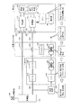
- FIG. 4 is a diagram for explaining the operation in the emergency power generation mode of the power supply system according to the embodiment of the present invention.
- the power supply system according to the embodiment of the present invention is different from the power supply system shown in FIG. 3 in that HEMS 300 further includes a switching unit 360, a power supply unit 380 and a switch 410. .
- the switching unit 360 is provided between the power supply lines 216 and 226 and the power supply unit 380.
- the switching unit 360 can switch the power supply source of the power supply unit 380 between the external power supply 500 and the vehicle 10.
- switching unit 360 includes voltage sensors 362 and 364, a control unit 366, and a contact unit 370.
- the voltage sensor 362 is provided on the power supply line 216 from the external power source 500 disposed between the charging cable 214 and the switchboard 510. Voltage sensor 362 detects the voltage of power supply line 216 and outputs the detected value to control unit 366.
- the voltage sensor 364 is provided on the power supply line 226 from the vehicle 10 disposed between the power supply cable 224 and the switchboard 510. Voltage sensor 364 detects the voltage of power supply line 226 and outputs the detected value to control unit 366.
- the contact part 370 is provided between the power supply line 216 and the power supply line 226 and the power supply part 380.
- the contact unit 370 is controlled by the control unit 366 and switches between a state where the power supply line 216 and the power supply unit 380 are connected and a state where the power supply line 226 and the power supply unit 380 are connected.
- the control unit 366 controls the connection state of the contact unit 370 in accordance with the detection values of the voltage sensors 362 and 364. Specifically, when the voltage of the power supply line 216 is a voltage and the voltage of the power supply line 226 is a non-voltage, the control unit 366 causes the power supply line 216 and the power supply unit 380 to be connected to each other. The contact portion 370 is controlled so as to be connected. On the other hand, when the voltage of the power supply line 216 is non-voltage and the voltage of the power supply line 226 is a voltage, the control unit 366 includes the power supply line 226 and the power supply unit 380 on the voltage side. The contact portion 370 is controlled so as to be connected. With such a configuration, the voltage of the feeder line that is a voltage is supplied to the power supply unit 380 and the power supply unit 380 is activated.
- the power supply unit 380 is configured to accept power of various specifications (frequency and voltage).
- the power supply unit 380 can convert the input electric power into electric power suitable for driving the electric devices constituting the HEMS 300 and the charging stand 200 and supply the electric power to the electric devices.
- the CPU 340 and the communication units 350 and 240 are activated in response to the supply of power from the power supply unit 380, the HEMS 300 and the charging stand 200 are in a state where they can communicate with the vehicle 10.
- the switch 410 is connected between the power supply line 226 and the load device 400.
- the switch 410 is controlled by a control signal RE from the CPU 340 and switches between power supply and interruption between the power supply line 226 and the load device 400.
- RE control signal
- the CPU 340 closes the switch 410 when communication is established among the HEMS 300, the charging station 200, and the vehicle 10.
- the power supply line 216 has a voltage, so that the power supply unit 380 receives power from the external power supply 500 via the contact part 370 of the switching unit 360.
- the CPU 340 and the communication units 350 and 240 are activated.
- the power supply from the external power supply 500 is interrupted, and the operations of the CPU 340 and the communication units 350 and 240 are stopped.
- the vehicle 10 cannot communicate with the HEMS 300 and the charging station 200 and cannot acquire the power generation parameters.
- the ECU 130 of the vehicle 10 when the emergency power generation mode is turned on due to a power failure of the external power supply 500, the ECU 130 of the vehicle 10 first supplies power from the vehicle 10 to the power supply unit 380 in the HEMS 300, thereby 350 and 240 are activated. Specifically, ECU 130 converts the discharged power from power storage device 100 and / or the generated power from power output device 135 into AC power for starting power supply unit 380 in HEMS 300. At this time, ECU 130 controls the power conversion operation in power supply unit 120 based on a predetermined specification. This predetermined specification is determined in advance and stored in the storage unit 145.
- AC power defined by the predetermined specification is supplied from the vehicle 10 to the HEMS 300.
- the power supply line 226 and the power supply unit 380 are connected by the switching unit 360.
- the power supply unit 380 is activated by receiving power from the vehicle 10 via the feeder line 226.
- the power supply unit 380 activates the CPU 340 and the communication units 350 and 240.
- the CPU 340 of the HEMS 300 sets the frequency and voltage of the external power supply 500, which are load specifications, as power generation parameters. Then, the CPU 340 transmits the power generation parameter to the vehicle 10 via the communication unit 350 and the communication unit 240 of the charging station 200.
- the ECU 130 when the power generation parameter is received by the communication unit 140, the ECU 130 rewrites the predetermined specification stored in the storage unit 145 to the received power generation parameter (load specification). Then, ECU 130 controls the power conversion operation of power feeding unit 120 based on the acquired load specification. As a result, appropriate AC power corresponding to the specifications of the load device 400 is output from the vehicle 10 and supplied to the HEMS 300 through the charging stand 200.
- the CPU 340 closes the switch 410 based on the establishment of communication with the vehicle 10. Thereby, the electric power from the vehicle 10 supplied to the HEMS 300 is supplied to the load device 400.
- FIG. 5 is a flowchart for explaining the operation of the vehicle and the charging station in the power supply system according to the embodiment of the present invention.
- step S12 CPU 340 opens switch 410 based on the fact that communication with vehicle 10 is disabled. Thereby, supply of the electric power to the load apparatus 400 is interrupted
- the ECU 130 determines whether the emergency power generation mode is turned on in step S03. Determine whether or not. If the emergency power generation mode is not turned on (NO in step S03), the process returns to step S03. Then, when the emergency power generation mode is turned on (when YES is determined in step S03), ECU 130 reads a predetermined specification stored in storage unit 145 in step S04. Then, in step S04, ECU 130 controls the power conversion operation of power feeding unit 120 based on the read predetermined specification, thereby generating AC power to be supplied from vehicle 10 to HEMS 300.
- step S ⁇ b> 14 the power supply unit 380 in the HEMS 300 is driven by receiving electric power supplied from the vehicle 10 via the switching unit 360.
- step S15 when the power supply unit 380 is activated in step S14, the communication unit 350 of the HEMS 300 and the communication unit 240 of the charging stand 200 are activated.
- step S16 the CPU 340 sets the specification of the load device 400 as a power generation parameter. Then, the CPU 340 transmits the set power generation parameter (specifications of the load device 400) to the vehicle 10 via the communication units 350 and 240. Further, CPU 340 closes switch 410 based on the establishment of communication between HEMS 300 and charging station 200 and vehicle 10 in step S16.
- ECU 130 supplies power to the outside of the vehicle by stopping discharging power storage device 100 and / or power generation of power output device 135 in step S 06. To stop.
- step S07 the ECU 130 changes the setting of the power generation parameter by rewriting a predetermined specification stored in advance in the storage unit 145 to the received load specification.
- step S08 ECU 130 controls the power conversion operation of power supply unit 120 based on the changed power generation parameter, thereby generating AC power to be supplied from vehicle 10 to load device 400. Thereby, power supply to the outside of the vehicle is resumed.
- AC power generated by the vehicle 10 is supplied to the load device 400 via the charging station 200 and the HEMS 300.
- the load device 400 is driven by receiving electric power supplied from the vehicle 10.
- power storage device 100 and power output device 135 correspond to “power generation unit”
- power supply unit 120 corresponds to “power supply unit”
- ECU 130 corresponds to “control device”.
- the HEMS 300 and the charging stand 200 correspond to a “power supply device”.
- the communication units 240 and 350 correspond to the “communication unit”
- the switching unit 360 corresponds to the “switching unit”
- the switch 410 corresponds to the “switch”.
- the vehicle, the HEMS, and the charging stand are activated by activating the communication unit of the HEMS and the charging stand with the electric power from the vehicle at the time of power failure of the external power supply.
- the specification load specification
- the electric power supplied to a load apparatus can be transmitted to a vehicle, it becomes possible to supply appropriate electric power according to a load specification from a vehicle.
- the load specification used at the time of external power supply is acquired by performing communication between the charging station connected to the vehicle and the HEMS and the vehicle at the time of a power failure of the external power supply, every time a power failure of the external power supply occurs In addition, the load specification is updated. Therefore, the load specification acquired by the vehicle and the specification of the load device on the power receiving side always coincide with each other, and power can be supplied to the load device.
- the charging unit 110 and the power feeding unit 120 have been described as separate devices. However, a configuration in which one power conversion unit capable of bidirectional power conversion for charging and power feeding may be provided.
- FIG. 1 illustrates a configuration in which the communication unit is provided in each of the charging stand 200 and the HEMS 300, but a configuration in which a communication unit for communicating with the vehicle 10 is provided in either the charging stand 200 or the HEMS 300 may be employed. .
- the present invention can be applied to a power supply system that supplies electric power from a vehicle to a load outside the vehicle.
Abstract
Priority Applications (5)
| Application Number | Priority Date | Filing Date | Title |
|---|---|---|---|
| EP11874813.6A EP2773017B1 (fr) | 2011-10-27 | 2011-10-27 | Système d'alimentation électrique et dispositif d'alimentation électrique |
| US14/238,063 US9184587B2 (en) | 2011-10-27 | 2011-10-27 | Power supply system and power feeding device |
| CN201180074404.XA CN104025420B (zh) | 2011-10-27 | 2011-10-27 | 电力供给系统和供电装置 |
| PCT/JP2011/074806 WO2013061442A1 (fr) | 2011-10-27 | 2011-10-27 | Système d'alimentation électrique et dispositif d'alimentation électrique |
| JP2013540577A JP5679071B2 (ja) | 2011-10-27 | 2011-10-27 | 電力供給システムおよび給電装置 |
Applications Claiming Priority (1)
| Application Number | Priority Date | Filing Date | Title |
|---|---|---|---|
| PCT/JP2011/074806 WO2013061442A1 (fr) | 2011-10-27 | 2011-10-27 | Système d'alimentation électrique et dispositif d'alimentation électrique |
Publications (1)
| Publication Number | Publication Date |
|---|---|
| WO2013061442A1 true WO2013061442A1 (fr) | 2013-05-02 |
Family
ID=48167308
Family Applications (1)
| Application Number | Title | Priority Date | Filing Date |
|---|---|---|---|
| PCT/JP2011/074806 WO2013061442A1 (fr) | 2011-10-27 | 2011-10-27 | Système d'alimentation électrique et dispositif d'alimentation électrique |
Country Status (5)
| Country | Link |
|---|---|
| US (1) | US9184587B2 (fr) |
| EP (1) | EP2773017B1 (fr) |
| JP (1) | JP5679071B2 (fr) |
| CN (1) | CN104025420B (fr) |
| WO (1) | WO2013061442A1 (fr) |
Cited By (1)
| Publication number | Priority date | Publication date | Assignee | Title |
|---|---|---|---|---|
| CN105705367A (zh) * | 2013-11-05 | 2016-06-22 | 丰田自动车株式会社 | 混合动力车辆、用于混合动力车辆的控制方法及用于混合动力车辆的控制器 |
Families Citing this family (13)
| Publication number | Priority date | Publication date | Assignee | Title |
|---|---|---|---|---|
| EP2762352A4 (fr) * | 2011-09-26 | 2016-06-01 | Toyota Motor Co Ltd | Véhicule et procédé de commande pour véhicule |
| EP2883740B1 (fr) * | 2012-08-13 | 2019-03-13 | Mitsubishi Electric Corporation | Dispositif de commande de propulsion de véhicule ferroviaire à moteur hybride |
| JP6040950B2 (ja) * | 2014-03-18 | 2016-12-07 | トヨタ自動車株式会社 | ハイブリッド車両およびその制御方法 |
| US20170174086A1 (en) * | 2015-12-16 | 2017-06-22 | Red Automotive Technologies Pty Ltd | Home and Vehicle Energy System |
| CN105680509B (zh) * | 2016-01-29 | 2018-12-14 | 易事特集团股份有限公司 | 具有断电处理功能的充电桩 |
| CN106042885B (zh) * | 2016-07-07 | 2018-10-12 | 中国第一汽车股份有限公司 | 一种插电式混合动力汽车用双向供电系统 |
| CN108521163A (zh) * | 2018-04-02 | 2018-09-11 | 北京新能源汽车股份有限公司 | 电动汽车双向充电设备及其供电系统 |
| US11440426B2 (en) * | 2018-05-22 | 2022-09-13 | Honda Motor Co., Ltd. | Electric vehicle and electric vehicle control method automatically selecting power supplied to outside from engine or battery of electric vehicle |
| WO2020186271A1 (fr) * | 2019-03-14 | 2020-09-17 | Marine Technologies LLC | Système et procédé permettant de réduire la consommation d'énergie et les émissions de vaisseaux marins |
| KR102603058B1 (ko) * | 2019-04-22 | 2023-11-16 | 현대자동차주식회사 | 친환경 차량용 충전 제어 시스템 및 방법 |
| EP3996949A1 (fr) * | 2019-07-11 | 2022-05-18 | Volvo Truck Corporation | Unité de commande pour un système de transmission de puissance électrique |
| FR3114056B1 (fr) * | 2020-09-14 | 2022-08-19 | Renault | Véhicule électrique et dispositif de commutation pour un réseau électrique domestique |
| CN114899893B (zh) * | 2022-05-12 | 2023-10-27 | 深圳市拓普联科技术股份有限公司 | 电力线通讯模组、设备、通讯方法、系统及存储介质 |
Citations (6)
| Publication number | Priority date | Publication date | Assignee | Title |
|---|---|---|---|---|
| JPH08154349A (ja) * | 1994-11-25 | 1996-06-11 | Japan Storage Battery Co Ltd | 交流無停電電源装置 |
| JP2001008380A (ja) * | 1999-06-17 | 2001-01-12 | Nissan Motor Co Ltd | 電力マネジメントシステム |
| JP2006158084A (ja) * | 2004-11-29 | 2006-06-15 | Toyota Motor Corp | 停電時電力供給装置及び住宅の配線構造 |
| JP2008283741A (ja) * | 2007-05-08 | 2008-11-20 | Matsushita Electric Works Ltd | 電力制御システム |
| JP2010154637A (ja) * | 2008-12-25 | 2010-07-08 | Honda Motor Co Ltd | 車両と家屋間の電力供給システム |
| JP2010239850A (ja) * | 2009-03-31 | 2010-10-21 | Tokyo Electric Power Co Inc:The | 充電システム、充電器、電動車両、および停電発生時の充電終了方法 |
Family Cites Families (3)
| Publication number | Priority date | Publication date | Assignee | Title |
|---|---|---|---|---|
| EP1819033A4 (fr) * | 2004-11-30 | 2014-09-10 | Toyota Motor Co Ltd | Systeme d'alimentation en courant alternatif, dispositif d'alimentation et vehicule possedant celui-ci |
| JP4678243B2 (ja) * | 2005-06-08 | 2011-04-27 | トヨタ自動車株式会社 | 電力供給システム |
| US20090030712A1 (en) * | 2007-07-26 | 2009-01-29 | Bradley D. Bogolea | System and method for transferring electrical power between grid and vehicle |
-
2011
- 2011-10-27 WO PCT/JP2011/074806 patent/WO2013061442A1/fr active Application Filing
- 2011-10-27 US US14/238,063 patent/US9184587B2/en active Active
- 2011-10-27 JP JP2013540577A patent/JP5679071B2/ja active Active
- 2011-10-27 EP EP11874813.6A patent/EP2773017B1/fr active Active
- 2011-10-27 CN CN201180074404.XA patent/CN104025420B/zh active Active
Patent Citations (6)
| Publication number | Priority date | Publication date | Assignee | Title |
|---|---|---|---|---|
| JPH08154349A (ja) * | 1994-11-25 | 1996-06-11 | Japan Storage Battery Co Ltd | 交流無停電電源装置 |
| JP2001008380A (ja) * | 1999-06-17 | 2001-01-12 | Nissan Motor Co Ltd | 電力マネジメントシステム |
| JP2006158084A (ja) * | 2004-11-29 | 2006-06-15 | Toyota Motor Corp | 停電時電力供給装置及び住宅の配線構造 |
| JP2008283741A (ja) * | 2007-05-08 | 2008-11-20 | Matsushita Electric Works Ltd | 電力制御システム |
| JP2010154637A (ja) * | 2008-12-25 | 2010-07-08 | Honda Motor Co Ltd | 車両と家屋間の電力供給システム |
| JP2010239850A (ja) * | 2009-03-31 | 2010-10-21 | Tokyo Electric Power Co Inc:The | 充電システム、充電器、電動車両、および停電発生時の充電終了方法 |
Non-Patent Citations (1)
| Title |
|---|
| See also references of EP2773017A4 * |
Cited By (1)
| Publication number | Priority date | Publication date | Assignee | Title |
|---|---|---|---|---|
| CN105705367A (zh) * | 2013-11-05 | 2016-06-22 | 丰田自动车株式会社 | 混合动力车辆、用于混合动力车辆的控制方法及用于混合动力车辆的控制器 |
Also Published As
| Publication number | Publication date |
|---|---|
| EP2773017B1 (fr) | 2017-03-01 |
| EP2773017A1 (fr) | 2014-09-03 |
| JP5679071B2 (ja) | 2015-03-04 |
| EP2773017A4 (fr) | 2015-07-22 |
| CN104025420B (zh) | 2016-03-09 |
| JPWO2013061442A1 (ja) | 2015-04-02 |
| US9184587B2 (en) | 2015-11-10 |
| US20140225437A1 (en) | 2014-08-14 |
| CN104025420A (zh) | 2014-09-03 |
Similar Documents
| Publication | Publication Date | Title |
|---|---|---|
| JP5679071B2 (ja) | 電力供給システムおよび給電装置 | |
| JP5673687B2 (ja) | 電力供給システムおよび車両 | |
| EP2631102B1 (fr) | Véhicule et système d'alimentation en énergie | |
| US9434257B2 (en) | Power supply connector, vehicle and control method for vehicle | |
| JP5630419B2 (ja) | 電力供給システムおよび車両 | |
| JP6156484B2 (ja) | 車両 | |
| EP3092149B1 (fr) | Vehicule hybride avec moyens de débranchement d'une batterie auxiliaire épuisée afin de permettre un plus rapide chargement de la batterie principale | |
| EP2596981B1 (fr) | Dispositif et procédé de régulation pour véhicule | |
| JP6044460B2 (ja) | 車両の電源装置 | |
| EP2752331A1 (fr) | Véhicule, système de charge et procédé de commande de véhicule | |
| JP5682537B2 (ja) | 電力供給システムおよび給電装置 | |
| JP5776482B2 (ja) | 電動車両 | |
| WO2013042244A1 (fr) | Système d'alimentation électrique pour véhicule | |
| JP5625715B2 (ja) | 車両の制御装置および制御方法 |
Legal Events
| Date | Code | Title | Description |
|---|---|---|---|
| WWE | Wipo information: entry into national phase |
Ref document number: 201180074404.X Country of ref document: CN |
|
| 121 | Ep: the epo has been informed by wipo that ep was designated in this application |
Ref document number: 11874813 Country of ref document: EP Kind code of ref document: A1 |
|
| WWE | Wipo information: entry into national phase |
Ref document number: 14238063 Country of ref document: US |
|
| REEP | Request for entry into the european phase |
Ref document number: 2011874813 Country of ref document: EP |
|
| WWE | Wipo information: entry into national phase |
Ref document number: 2011874813 Country of ref document: EP |
|
| ENP | Entry into the national phase |
Ref document number: 2013540577 Country of ref document: JP Kind code of ref document: A |
|
| NENP | Non-entry into the national phase |
Ref country code: DE |