WO2013057761A1 - スクリューポンプ、及びスクリューポンプ用ロータ - Google Patents
スクリューポンプ、及びスクリューポンプ用ロータ Download PDFInfo
- Publication number
- WO2013057761A1 WO2013057761A1 PCT/JP2011/005857 JP2011005857W WO2013057761A1 WO 2013057761 A1 WO2013057761 A1 WO 2013057761A1 JP 2011005857 W JP2011005857 W JP 2011005857W WO 2013057761 A1 WO2013057761 A1 WO 2013057761A1
- Authority
- WO
- WIPO (PCT)
- Prior art keywords
- tooth
- rotor
- lead portion
- unequal
- screw pump
- Prior art date
- Legal status (The legal status is an assumption and is not a legal conclusion. Google has not performed a legal analysis and makes no representation as to the accuracy of the status listed.)
- Ceased
Links
Images




Classifications
-
- F—MECHANICAL ENGINEERING; LIGHTING; HEATING; WEAPONS; BLASTING
- F04—POSITIVE - DISPLACEMENT MACHINES FOR LIQUIDS; PUMPS FOR LIQUIDS OR ELASTIC FLUIDS
- F04C—ROTARY-PISTON, OR OSCILLATING-PISTON, POSITIVE-DISPLACEMENT MACHINES FOR LIQUIDS; ROTARY-PISTON, OR OSCILLATING-PISTON, POSITIVE-DISPLACEMENT PUMPS
- F04C18/00—Rotary-piston pumps specially adapted for elastic fluids
- F04C18/08—Rotary-piston pumps specially adapted for elastic fluids of intermeshing-engagement type, i.e. with engagement of co-operating members similar to that of toothed gearing
- F04C18/12—Rotary-piston pumps specially adapted for elastic fluids of intermeshing-engagement type, i.e. with engagement of co-operating members similar to that of toothed gearing of other than internal-axis type
- F04C18/14—Rotary-piston pumps specially adapted for elastic fluids of intermeshing-engagement type, i.e. with engagement of co-operating members similar to that of toothed gearing of other than internal-axis type with toothed rotary pistons
- F04C18/16—Rotary-piston pumps specially adapted for elastic fluids of intermeshing-engagement type, i.e. with engagement of co-operating members similar to that of toothed gearing of other than internal-axis type with toothed rotary pistons with helical teeth, e.g. chevron-shaped, screw type
-
- F—MECHANICAL ENGINEERING; LIGHTING; HEATING; WEAPONS; BLASTING
- F04—POSITIVE - DISPLACEMENT MACHINES FOR LIQUIDS; PUMPS FOR LIQUIDS OR ELASTIC FLUIDS
- F04C—ROTARY-PISTON, OR OSCILLATING-PISTON, POSITIVE-DISPLACEMENT MACHINES FOR LIQUIDS; ROTARY-PISTON, OR OSCILLATING-PISTON, POSITIVE-DISPLACEMENT PUMPS
- F04C18/00—Rotary-piston pumps specially adapted for elastic fluids
- F04C18/08—Rotary-piston pumps specially adapted for elastic fluids of intermeshing-engagement type, i.e. with engagement of co-operating members similar to that of toothed gearing
- F04C18/082—Details specially related to intermeshing engagement type pumps
- F04C18/084—Toothed wheels
Definitions
- the present invention relates to a screw pump.
- Patent Document 1 a screw pump using a pair of screw-like rotors having an unequal lead portion and an equal lead portion has been proposed (for example, Patent Document 1). Further, such a rotor is complicated to process. Therefore, a machine tool that improves the productivity of the rotor has also been proposed (for example, Patent Document 2).
- the peripheral speeds of a pair of rotors may be different from each other.
- the dust may adhere to the tooth surface of the rotor.
- the moving speeds of the tooth surfaces of one rotor and the tooth surfaces of the other rotor are different, so the dust removal efficiency can be improved.
- the rotor diameters are made different (the rotation speed is the same), or a combination of these is possible. Can be mentioned.
- the gaps between the tooth surfaces at the unequal lead portions between the pair of rotors become too large, or conversely there are almost no gaps. May end up. As a result, the target pump performance may not be obtained.
- An object of the present invention is to provide a screw pump including a rotor having a tooth surface shape in which a more suitable gap can be formed.
- the first rotor is a first unequal.
- a screw pump including a rotor having a tooth surface shape in which a more suitable gap can be formed.
- Sectional drawing of the screw pump which concerns on one Embodiment of this invention Sectional drawing of the said screw pump.
- the flowchart which shows the manufacture procedure example of a rotor.
- Explanatory drawing of a tooth trace curve Explanatory drawing of the creation method of a three-dimensional model.
- FIG.1 and FIG.2 is sectional drawing of the screw pump 100 which concerns on one Embodiment of this invention, and is sectional drawing from which a cut surface differs mutually.
- the screw pump 100 includes a housing 110 having a discharge port 111 and a suction port 112.
- the housing 110 is provided with a pair of rotating shafts 101 and 101 extending in parallel with each other.
- the rotary shafts 101 and 101 are rotatably supported by bearing portions 130 and 130, respectively.
- a seal member 150 is provided between the housing 110 and the rotary shafts 101 and 101 in order to prevent leakage of fluid to be pumped and prevent dust and the like from entering the housing 110 from the outside. .
- a gear (timing gear) 140 is fixed to one of the pair of rotating shafts 101 and 101, and a gear (timing gear) 141 is fixed to the other.
- the gear 140 and the gear 141 mesh with each other.
- the gear 141 is further engaged with a gear 142 that is rotated by a drive source (not shown) (for example, a motor).
- the gear 142 is rotated by driving the drive source, and the rotational force is transmitted to the pair of rotating shafts 101 and 101 via the gears 140 and 141. As a result, the pair of rotating shafts 101 and 101 rotate.
- the housing 110 accommodates screw-like rotors 120 and 121 that mesh with each other.
- the rotor 120 is fixed coaxially to one rotating shaft 101.
- the rotor 121 is coaxially fixed to the other rotating shaft 101.
- the rotors 120 and 121 rotate integrally with the rotation shafts 101 and 101. As the rotors 120 and 121 rotate, the fluid to be pumped is pumped from the suction port 112 to the discharge port 101.
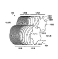
- FIG. 3 shows the rotors 120 and 121 in mesh with each other.
- the rotor 120 has a plurality of tooth grooves formed on the peripheral surface.
- Each tooth gap includes a tooth bottom 1202, tooth surfaces 1203 and 1204, and an outer peripheral portion 1201 between adjacent tooth gaps.
- the rotor 121 is formed with a plurality of teeth on the circumferential surface that mesh with the tooth grooves of the rotor 120.
- Each tooth includes a tooth tip 1211, a tooth bottom 1212, and tooth surfaces 1213 and 1214.
- the tooth surface 1204 located on the suction side is the upper tooth surface
- the tooth surface 1203 located on the discharge side is the lower tooth surface
- the tooth surface 1213 located on the suction side is the upper tooth surface
- the tooth surface 1214 located on the discharge side is the lower tooth.
- the rotor 120 is a female rotor with six tooth spaces, and the rotor 121 is a male rotor with five teeth.
- the peripheral speeds of the rotors 120 and 121 can be made different from each other.
- the moving speeds of the tooth surfaces 1203 and 1214 facing each other and the moving speeds of the tooth surfaces 1204 and 1213 facing each other can be made different.
- the dust removal efficiency on the tooth surfaces 1203, 1204, 1213, and 1214 can be improved.
- the rotor 120 has, on the suction side, an unequal lead portion 120A in which a tooth groove is formed with an unequal lead / unequal inclination angle, and an equal lead portion 120B in which a tooth groove is formed at an equal lead / equal inclination angle on the discharge side.
- the rotor 121 meshes with the unequal lead portion 120A on the suction side, the teeth are formed with unequal leads and unequal inclination angles, and the unequal lead portion 121A meshes with the equal lead portion 120B on the discharge side, the teeth etc.
- Each of the leads has an equal lead portion 121B formed at an equal inclination angle.
- the unequal lead portions 120A and 121A are portions where the suction side has a larger lead angle (inclination angle) than the discharge side, and the lead angle gradually decreases from the suction side toward the discharge side. is there.
- the equal lead portions 120A and 121A are portions having the same lead angle (inclination angle) from the suction side to the discharge side.
- the rotors 120 and 121 are provided with both unequal lead portions and equal lead portions, but only the unequal lead portions may be provided.
- the gap between the tooth surfaces 1203 and 1214 facing each other is different.
- the gap or the gap between the tooth surface 1204 and the tooth surface 1213 facing each other is too large or too small. Therefore, a method for designing the gap to be appropriate will be described.
- FIG. 4 is a flowchart showing an example of the manufacturing procedure of the rotor.
- the overall flow is outlined.
- S1 the specifications of the screw pump 100 are determined.
- S2 the rotors 120 and 121 that satisfy the specifications of S1 are designed.
- S3 a three-dimensional shape model of the rotors 120 and 121 is created according to the contents designed in S2. Creation of a three-dimensional shape model can be performed on a computer (hereinafter referred to as a CAD system) in which three-dimensional CAD software is installed.
- a computer hereinafter referred to as a CAD system
- the clearance between the tooth surfaces of the rotor 120 and the rotor 121 is evaluated based on the three-dimensional shape model of the rotors 120 and 121 created in S3. Specifically, with respect to the unequal lead portions 120A and 121A, the gap between the lower tooth surface 1203 of the rotor 120 and the lower tooth surface 1214 of the rotor 121, and the upper tooth surface 1204 of the rotor 120 and the upper tooth surface of the rotor 121 Evaluate whether or not the gap with 1213 is appropriate. The clearance is evaluated on the CAD system.
- the three-dimensional shape models of the rotors 120 and 121 are virtually assembled and meshed with each other. And the tooth surface and tooth surface which evaluate a clearance gap are designated, and the distance between tooth surfaces is calculated by a CAD system. If the calculated distance is appropriate, the process proceeds to S5, and if it is inappropriate, the process proceeds to S10.
- the gap between the tooth surfaces of the unequal lead portions 120A and 121A is preferably 300 to 500 microns, particularly 350 to 450 microns in the vicinity of the starting point on the suction side, and gradually decreases gradually as it advances to the discharge side.
- the starting point of the equal lead is preferably about 200 microns.
- Unequal lead 120A Rotor diameter: approx. 21 cm, number of tooth gaps: 6, inlet angle on the suction side of the unequal lead part: 45 degrees, outlet angle on the discharge side of the unequal lead part (slope angle of the equal lead part): 5 degrees Part 121A Rotor diameter: about 25 cm, number of teeth: 5, inlet angle on the suction side of the unequal lead portion: 35 degrees, outlet angle on the discharge side of the unequal lead portion (tilt angle of the equal lead portion): 3.5 degrees rotor ( 121) Rotation speed: 7200 rpm
- the gap between the tooth surfaces of the unequal lead portions 120A and 121A does not necessarily have to be uniform in the rotor axial direction.
- the gap on the suction side is preferably larger than the discharge side.
- the suction-side gap is preferably 1.5 to 2.5 times, particularly 1.8 to 2.3 times the discharge-side gap.
- the teeth may expand outward due to temperature rise or centrifugal force.
- the tooth surfaces may interfere with each other due to tooth expansion.
- machining programs for the rotors 120 and 121 are created from the three-dimensional shape model created in S3.
- the machining program can be created on a computer in which CAM software is installed.
- the machining program created in S5 is input to the CNC machine tool, and the rotors 120 and 121 are actually created.
- the rotor design is changed and the process returns to S3, and the same processing is repeated.
- the three-dimensional shape model of the rotors 120 and 121 can be created if the cross-sectional shape perpendicular to the axis of the rotor and the tooth trace are determined.
- the cross-sectional shape perpendicular to the axis is a cross-sectional shape when the rotor is cut along a plane orthogonal to the axial direction.
- the tooth trace curve defines the arc length from the reference position of the rotor and the position in the axial direction, and defines each surface of the tooth surface, the tooth tip, and the tooth bottom.
- FIG. 5 shows an example of a tooth trace curve
- FIG. 6 is an explanatory diagram of a method for creating a three-dimensional shape model.
- the axial direction of the rotor is the Z direction
- the end surface on the suction side of the rotor is the origin of coordinates.
- the tooth trace curves L1 and L2 shown in FIG. 5 are defined for each rotor.
- the tooth trace curve L 1 defines each tooth of the rotor 121
- the tooth trace curve L 2 defines each tooth gap of the rotor 120.
- the tooth trace curve is arcuate at the unequal lead portion and is straight at the equal lead portion.
- R is the distance between a point selected from the contour line of the cross-sectional shape perpendicular to the axis and the rotor axis
- ⁇ is the rotation angle of the rotor
- Z is the rotor axis.
- shape SC indicates a cross-sectional shape perpendicular to the axis of the rotor to be modeled at the origin. If the point P is taken on the contour of the shape SC and the distance from the point P to the axis of the shape SC is R, the tooth trace curve L1 shown in the figure shows the position of the point P in the Z direction with respect to the rotation angle of the rotor. It will be.
- the axis-perpendicular shape SC ′ when the rotation angle is ⁇ a is obtained by rotating the shape SC about the axis by ⁇ a.
- the coordinates in the Z direction of the shape SC ′ in the three-dimensional space are the tooth trace curves L1 to Za.
- ⁇ Axis perpendicular cross-sectional shape and tooth trace curve design> In the process of S2 described above, the cross-sectional shape perpendicular to the axis and the tooth trace curve are mainly designed.
- the tooth trace for example, the outer diameter of the rotor, the length of the unequal lead portion in the Z direction, the number of leads of the unequal lead portion (number of turns), the inlet angle of the unequal lead portion, the unequal lead portion The outlet angle (equal lead portion angle), the length of the equal lead portion in the Z direction, the number of leads (number of turns) of the equal lead portion, and the like are required.
- Z is the position of the rotor in the axial direction
- Z is the position of the rotor in the axial direction
- Z is the position of the rotor in the axial direction
- ⁇ ⁇
- ⁇ a constant determined by the condition of the exit coordinates of the unequal lead
- R is the radius
- ⁇ is the rotation angle
- ⁇ is the entrance angle
- ⁇ 0 is the exit angle .
- the screw pump can be designed by determining the cross-sectional shape perpendicular to the axis from the above formula 1, the root diameter of each rotor, the number of teeth of each rotor, the inter-axis distance between the rotors, and the like.
- the design change must be made within a range that does not significantly impair the original specification (S1).
- the design change may be made only on one of the two rotors or on both, but it is easier to make the change on only one of the two rotors.
- S1 original specification
- the design change may be made only on one of the two rotors or on both, but it is easier to make the change on only one of the two rotors.
- FIG. 7 shows an example of each tooth trace curve of the upper tooth surface 1213 and the lower tooth face 1214 of the rotor 121 and a method of creating a three-dimensional shape model based on these tooth trace curves.
- the two types of tooth traces after the change are derived from the pre-change tooth traces.
- the tooth trace curves L11 and L12 in FIG. 7 are derived from the tooth trace curve L1 shown in FIG. 6, for example.
- the tooth trace curves L11 and L12 first set a correction gap between the upper tooth surfaces and a correction gap between the lower tooth surfaces at the entrance (end portion on the suction side) of the unequal lead portion. Then, the term of R ⁇ ⁇ in the above equation 1 is modified so that these correction gaps are realized. At this time, these correction gaps may be gradually and gradually reduced from the inlet side (suction side) to the outlet side (discharge side) of the unequal lead portion.
- R ⁇ ⁇ + C ⁇ f (R ⁇ ⁇ ) is substituted into the term of R ⁇ ⁇ in Equation 1 above.
- f (R ⁇ ⁇ ) is a function that becomes zero at the end point of the unequal lead portion (start point of the equal lead portion). Then, the value of C is determined so that the correction gap is appropriate.
- the deformation formula of the above formula 1 obtained in this way becomes the tooth trace after the change.
- One of the tooth trace curves for the upper tooth surface and the lower tooth surface may be a tooth trace curve before the change. That is, one of the upper and lower tooth surface tooth trace curves may be a tooth trace curve L1, and the other may be a tooth trace curve changed from the tooth trace curve L1.
- the shape SC indicates the cross-sectional shape perpendicular to the axis of the rotor at the origin. If the point P is taken on the contour of the shape SC and the distance from the point P to the axis of the shape SC is R, the tooth trace curves L11 and L12 shown in the figure are the positions of the point P in the Z direction with respect to the rotation angle of the rotor. Is the same as in the case of FIG.
- FIG. 6 is different from the case of FIG. 6 in that a cross-sectional shape perpendicular to the axis is obtained for each of the tooth trace curves L11 and L12 according to the coordinates in the Z direction.
- one axis-perpendicular cross-sectional shape is created by superimposing two axis-perpendicular cross-sectional shapes and taking the logical sum (OR logic) of these figures.
- an axially perpendicular cross-sectional shape SC1 having a rotation angle ⁇ 1 is obtained from the tooth trace curve L12. Further, from the tooth trace curve L11, an axial perpendicular cross-sectional shape SC2 having a rotation angle ⁇ 2 is obtained. Then, the axis perpendicular cross-sectional shape SC ', which is a figure obtained by logically summing the axis perpendicular cross-sectional shape SC1 and the axis perpendicular cross-sectional shape SC2, is the axis perpendicular cross-sectional shape of the target rotor at the coordinate Zb.
- one tooth surface TS1 is a tooth surface based on the tooth trace curve L11
- the other tooth surface TS2 is a tooth surface based on the tooth trace curve L12.
- the present invention is not limited to the above embodiment, and various changes and modifications can be made without departing from the spirit and scope of the present invention.
- the tooth trace curve may be changed not on the tooth surface of the male rotor (121) but on the tooth surface of the female rotor (120), or on the tooth surfaces of both male and female rotors. It may be. Therefore, in order to make the scope of the present invention public, the following claims are attached.
Landscapes
- Engineering & Computer Science (AREA)
- Mechanical Engineering (AREA)
- General Engineering & Computer Science (AREA)
- Rotary Pumps (AREA)
Abstract
本発明は、スクリュー状の第1ロータと、前記第1ロータの歯と噛み合う歯溝を有するスクリュー状の第2ロータと、を備えたスクリューポンプを提供する。前記第1ロータが第1不等リード部を有し、前記第2ロータが前記第1不等リード部に噛み合う第2不等リード部を有する。前記第1不等リード部の歯を形成する二つの歯面、及び、前記第2不等リード部の歯溝を形成する二つの歯面、のうちの少なくともいずれかが、互いに異なる歯筋曲線に基づき形成されている。
Description
本発明はスクリューポンプに関する。
より高い圧縮比を得るため、不等リード部及び等リード部を有する一対のスクリュー状のロータを用いたスクリューポンプが提案されている(例えば特許文献1)。また、このようなロータはその加工が複雑化する。そこで、ロータの生産性を向上させる工作機械も提案されている(例えば特許文献2)。
スクリューポンプにおいては、一対のロータの周速を相互に異ならせたい場合がある。例えば、スクリューポンプによって圧送する流体に粉塵が含まれる場合、ロータの歯面上に粉塵が付着する場合がある。一対のロータの周速を互いに異ならせることで、一方のロータの歯面と他方のロータの歯面との移動速度が異なるため、粉塵の除去効率を向上できる。一対のロータの周速を異ならせる方法としては、例えば、一対のロータ間で歯数及び歯溝数を異ならせること、ロータ径を異ならせる(回転数は同一)こと、或いは、これらの併用が挙げられる。
しかし、一対のロータ間で歯数及び歯溝数やロータ径を異ならせると、一対のロータ間でそれらの不等リード部における歯面間の隙間が大きくなりすぎたり、逆に隙間がほとんどなくなってしまう場合がある。その結果、目的とするポンプ性能が得られない場合がある。
本発明の目的は、より好適な隙間が形成され得る歯面形状を有するロータを備えたスクリューポンプを提供することにある。
本発明によれば、スクリュー状の第1ロータと、前記第1ロータの歯と噛み合う歯溝を有するスクリュー状の第2ロータと、を 備えたスクリューポンプにおいて、前記第1ロータが第1不等リード部を有し、前記第2ロータが前記第1不等リード部に噛み合う第2不等リード部を有し、前記第1不等リード部の歯を形成する二つの歯面、及び、前記第2不等リード部の歯溝を形成する二つの歯面、のうちの少なくともいずれかが、互いに異なる歯筋曲線に基づき形成されていることを特徴とするスクリューポンプが提供される。
本発明によれば、より好適な隙間が形成され得る歯面形状を有するロータを備えたスクリューポンプを提供することができる。
<全体の構成>
図1及び図2は本発明の一実施形態に係るスクリューポンプ100の断面図であり、互いに切断面が異なる断面図である。スクリューポンプ100は、吐出口111及び吸入口112を有するハウジング110を備える。ハウジング110には、互いに平行に延設された一対の回転軸101、101が設けられている。回転軸101、101は、それぞれ、軸受部130、130により回転自在に支持されている。また、圧送する流体の漏れを防止すると共に、外部から粉塵等がハウジング110内部へ侵入することを防止するため、ハウジング110と回転軸101、101との間にはシール部材150が設けられている。
図1及び図2は本発明の一実施形態に係るスクリューポンプ100の断面図であり、互いに切断面が異なる断面図である。スクリューポンプ100は、吐出口111及び吸入口112を有するハウジング110を備える。ハウジング110には、互いに平行に延設された一対の回転軸101、101が設けられている。回転軸101、101は、それぞれ、軸受部130、130により回転自在に支持されている。また、圧送する流体の漏れを防止すると共に、外部から粉塵等がハウジング110内部へ侵入することを防止するため、ハウジング110と回転軸101、101との間にはシール部材150が設けられている。
一対の回転軸101、101の一方には歯車(タイミングギア)140が、他方には歯車(タイミングギア)141がそれぞれ固定されている。歯車140と歯車141とは互いに噛み合う。歯車141には、更に、不図示の駆動源(例えばモータ)により回転される歯車142が噛み合っている。駆動源の駆動により歯車142が回転し、その回転力が歯車140、141を介して一対の回転軸101、101に伝達される。これにより一対の回転軸101、101が回転することになる。
ハウジング110内には相互に噛み合うスクリュー状のロータ120、121が収容されている。ロータ120は一方の回転軸101に同軸で固定されている。また、ロータ121は他方の回転軸101に同軸で固定されている。ロータ120、121は回転軸101、101と一体的に回転する。そして、ロータ120、121の回転により、吸入口112から吐出口101へ、圧送対象の流体が圧送される。
<ロータの構成>
図3は互いに噛み合った状態のロータ120、121を示す。ロータ120には複数の歯溝が周面に形成されている。各歯溝は歯底1202、歯面1203、1204、隣接歯溝間の外周部1201から構成されている。ロータ121には、ローター120の歯溝に噛み合う複数の歯が周面に形成されている。各歯は歯先1211、歯底1212、歯面1213、1214から構成されている。
図3は互いに噛み合った状態のロータ120、121を示す。ロータ120には複数の歯溝が周面に形成されている。各歯溝は歯底1202、歯面1203、1204、隣接歯溝間の外周部1201から構成されている。ロータ121には、ローター120の歯溝に噛み合う複数の歯が周面に形成されている。各歯は歯先1211、歯底1212、歯面1213、1214から構成されている。
なお、ロータ120の一つの歯底1202に対する一対の歯面1203、1204のうち、吸入側に位置している歯面1204を上歯面、吐出側に位置している歯面1203を下歯面と呼び、ロータ121の一つの歯先1211に対する一対の歯面1213、1214のうち、吸入側に位置している歯面1213を上歯面、吐出側に位置している歯面1214を下歯面と、それぞれ呼ぶ場合がある。
ロータ120は歯溝数が6つの雌型ロータであり、ロータ121は歯数が5つの雄型ロータである。このようにロータ120の歯溝数と、ロータ121の歯数を異ならせることで、ロータ120、121の周速を互いに異ならせることができる。周速を互いに異ならせることで、互いに向かい合う歯面1203と歯面1214との移動速度、及び、互いに向かい合う歯面1204と歯面1213との移動速度を異ならせることができる。この結果、歯面1203、1204、1213、1214上の粉塵の除去効率を向上できる。
なお、ロータ120、121で外径を異ならせることで、同じ回転数でもこれらの周速を互いに異ならせることもできる。また、ロータ120の歯溝数とロータ121の歯数を異ならせると共に、ロータ120、121の外径を異ならせてもよい。
ロータ120は吸入側に、歯溝が不等リード・不等傾斜角で形成された不等リード部120Aを、吐出側に歯溝が等リード・等傾斜角で形成された等リード部120Bを、それぞれ有している。また、ロータ121は吸入側に、不等リード部120Aと噛み合う、歯が不等リード・不等傾斜角で形成され不等リード部121Aを、吐出側に等リード部120Bと噛み合う、歯が等リード・等傾斜角で形成された等リード部121Bを、それぞれ有している。
不等リード部120A、121Aは吸入側の方が吐出側よりもリード角(傾斜角)が大きくなっており、しかも、吸入側から吐出側に向かってリード角が徐々に小さくなっている部分である。等リード部120A、121Aは吸入側から吐出側に向かってリード角(傾斜角)が等しい部分である。本実施形態では、ロータ120、121に不等リード部と等リード部との双方を設けたが、不等リード部のみを設けるようにしてもよい。
このように不等リード部120A、121Aを設け、かつ、不等リード部120Aの歯溝数と不等リード部121Aの歯数が異なる場合、互いに向かい合う歯面1203と歯面1214との間の隙間、或いは、互いに向かい合う歯面1204と歯面1213との隙間が大きすぎたり、小さすぎたりする場合がある。そこで、この隙間が適切になるように設計する方法について説明する。
<ロータ設計方法>
図4はロータの製作手順例を示すフローチャートである。まず、全体の流れを概説する。S1ではスクリューポンプ100の仕様を決定する。ここではポンプの要求能力等を決定する。S2ではS1の仕様を満足するロータ120、121の設計を行う。S3ではS2で設計した内容に従い、ロータ120、121の3次元形状モデルを作成する。3次元形状モデルの作成は、3次元CADソフトウエアがインストールされたコンピュータ(以下、CADシステムという。)上で行うことができる。
図4はロータの製作手順例を示すフローチャートである。まず、全体の流れを概説する。S1ではスクリューポンプ100の仕様を決定する。ここではポンプの要求能力等を決定する。S2ではS1の仕様を満足するロータ120、121の設計を行う。S3ではS2で設計した内容に従い、ロータ120、121の3次元形状モデルを作成する。3次元形状モデルの作成は、3次元CADソフトウエアがインストールされたコンピュータ(以下、CADシステムという。)上で行うことができる。
S4ではS3で作成したロータ120、121の3次元形状モデルに基づいて、ロータ120とロータ121の歯面の隙間の評価を行う。詳細には、不等リード部120A、121Aについて、ロータ120の下歯面1203とロータ121の下歯面1214との間の隙間、及び、ロータ120の上歯面1204とロータ121の上歯面1213との間の隙間が適切であるかを評価する。隙間の評価はCADシステム上で行う。
つまり、CADシステム上で、ロータ120、121の各3次元形状モデルを仮想的に組み付け、互いに噛み合った状態とする。そして、隙間を評価する歯面と歯面を指定し、CADシステムに歯面間の距離を演算させる。演算された距離が適切であればS5へ進み、不適切であればS10へ進む。
不等リード部120A、121Aにおける歯面間の隙間は、例えば、以下の条件の場合、吸入側始点近傍では300~500ミクロン、特に350~450ミクロンが好ましく、吐出側に進むに従い、滑らかに漸減して等リードの始点では200ミクロン程度であることが好ましい。
不等リード部120A
ロータ径:約21cm、歯溝数:6、不等リード部の吸入側の入口角度:45度、不等リード部の吐出側の出口角度(等リード部の傾斜角度):5度
不等リード部121A
ロータ径:約25cm、歯数:5、不等リード部の吸入側の入口角度:35度、不等リード部の吐出側の出口角度(等リード部の傾斜角度):3.5度
ロータ(121)回転数:7200rpm
不等リード部120A、121Aにおける歯面間の隙間はロータ軸方向に渡って必ずしも均一である必要はなく、むしろ、吸入側の方が吐出側よりも隙間が大きいことが好ましい。例えば、吸入側の隙間は、吐出側の隙間の1.5倍~2.5倍、特に1.8倍~2.3倍であることが好ましい。スクリューポンプ100の動作時には、温度上昇や遠心力により、歯が外側に膨張する場合がある。吸入側においては、歯の傾斜角が大きいため、歯の膨張により歯面間が干渉する場合がある。吸入側の歯面間の隙間を相対的に大きくしておくことで、このような歯面間の干渉を回避できる。
S5ではS3で作成した3次元形状モデルから、ロータ120、121の加工プログラムを作成する。加工プログラムの作成は、CAMソフトウエアがインストールされたコンピュータ上で行うことができる。S6ではS5で作成した加工プログラムをCNC工作機械に入力し、実際にロータ120、121を作成する。S10ではロータの設計を変更してS3へ戻り、同様の処理を繰り返す。
<3次元形状モデル>
ロータ120、121の3次元形状モデルは、ロータの軸直角断面形状と、歯筋曲線とが決まれば作成できる。軸直角断面形状とはロータをその軸方向と直交する面で切断したときの断面形状である。歯筋曲線は、ロータの基準位置からの円弧長と、軸方向の位置とを規定し、歯面、歯先、歯底の各面を規定することになる。
ロータ120、121の3次元形状モデルは、ロータの軸直角断面形状と、歯筋曲線とが決まれば作成できる。軸直角断面形状とはロータをその軸方向と直交する面で切断したときの断面形状である。歯筋曲線は、ロータの基準位置からの円弧長と、軸方向の位置とを規定し、歯面、歯先、歯底の各面を規定することになる。
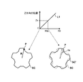
図5は歯筋曲線の一例を示し、図6は3次元形状モデルの作成方法の説明図である。ロータの軸方向をZ方向とし、また、ロータの吸入側の端面を座標の原点としている。
図5に示す歯筋曲線L1、L2はロータ毎に規定する。例えば、歯筋曲線L1はロータ121の各歯を規定し、歯筋曲線L2はロータ120の各歯溝を規定する。歯筋曲線は不等リード部では弧状をなし、等リード部で直線となる。図5中、Rは軸直角断面形状の輪郭線上から選択された点と、ロータ軸心との距離、θはロータの回転角度、Zはロータ軸である。
図6を参照して、形状SCは原点におけるモデル作成対象のロータの軸直角断面形状を示している。形状SCの輪郭上に点Pを取り、点Pから形状SCの軸心までの距離をRとすると、同図に示す歯筋曲線L1はロータの回転角度に対する点PのZ方向の位置を示すことになる。
回転角度がθaのときの軸直角断面形状SC’は、形状SCをその軸心回りにθaだけ回転させたものとなる。そして、3次元空間上における形状SC’のZ方向の座標は、歯筋曲線L1からZaとなる。Z方向の座標を微小量ずつ変化させて、そのときの回転角度から軸直角断面形状SC’を求めてゆき、これらをZ方向に積み重ねてゆくと、ロータの3次元形状モデルができあがることになる。上述したS3の工程ではこのようにしてロータの3次元形状モデルを作成することができる。
<軸直角断面形状と歯筋曲線の設計>
上述したS2の工程では、主として軸直角断面形状と歯筋曲線とを設計することになる。歯筋曲線の設計には、例えば、ロータの外径、不等リード部のZ方向の長さ、不等リード部のリード数(巻き数)、不等リード部の入口角度、不等リード部の出口角度(等リード部角度)、等リード部のZ方向の長さ、及び等リード部のリード数(巻き数)等が必要となる。
上述したS2の工程では、主として軸直角断面形状と歯筋曲線とを設計することになる。歯筋曲線の設計には、例えば、ロータの外径、不等リード部のZ方向の長さ、不等リード部のリード数(巻き数)、不等リード部の入口角度、不等リード部の出口角度(等リード部角度)、等リード部のZ方向の長さ、及び等リード部のリード数(巻き数)等が必要となる。
これらの数値を織り込んだ歯筋曲線のうち不等リード部については
Z=tanζ×R×Θ-ξ×(R×Θ)η-(式1)
で表わすことが出来る。等リード部については式1でζ=ζ0、ξ=0として表わすことが出来る。
ここで、Z:ロータの軸方向の位置、ξ、η:不等リード部の出口座標の条件により決まる定数、R:半径、Θ:回転角、ζ:入口角、ζ0:出口角である。
Z=tanζ×R×Θ-ξ×(R×Θ)η-(式1)
で表わすことが出来る。等リード部については式1でζ=ζ0、ξ=0として表わすことが出来る。
ここで、Z:ロータの軸方向の位置、ξ、η:不等リード部の出口座標の条件により決まる定数、R:半径、Θ:回転角、ζ:入口角、ζ0:出口角である。
そして、上記式1や、各ロータの歯底外径、各ロータの歯数、ロータ間の軸間距離等から軸直角断面形状を決定し、スクリューポンプを設計することができる。
<設計変更>
図4のS10の設計変更について説明する。S4での歯面間での隙間が不適切であった場合、適切となるようにロータの設計変更を行う。変更の対象は、歯筋曲線である。
図4のS10の設計変更について説明する。S4での歯面間での隙間が不適切であった場合、適切となるようにロータの設計変更を行う。変更の対象は、歯筋曲線である。
設計変更は、当初の仕様(S1)を大きく損なわない範囲で行う必要がある。設計変更は、2つのロータのうちの一方にのみ行ってもよいし、双方に行ってもよいが、一方のみに行う方が簡便になる。以下、一方のロータについてその歯筋曲線を変更する例について説明する。
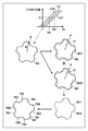
本実施形態では、変更後の歯筋曲線として、上歯面と下歯面とで異なる歯筋曲線を設定する。図7はロータ121の上歯面1213及び下歯面1214の各歯筋曲線の例と、これらの歯筋曲線に基づく3次元形状モデルの作成方法を示している。
変更後の2種類の歯筋曲線は、変更前の歯筋曲線から導かれる。図7の歯筋曲線L11、L12は例えば図6に示した歯筋曲線L1から導かれる。歯筋曲線L11、L12は、まず、不等リード部の入口(吸入側の端部)での、上歯面間の補正隙間、下歯面間の補正隙間を設定する。そして、これらの補正隙間が実現されるように上記式1のR×Θの項を変形する。その際、これらの補正隙間が、不等リード部の入口側(吸入側)から出口側(吐出側)へ向かって滑らかに漸減するようにしてもよい。具体的には、上記式1のR×Θの項に、R×Θ+C×f(R・Θ)を代入する。ここで、f(R・Θ)は、不等リード部の終点(等リード部の始点)で零になるような関数である。そして補正隙間が適切なものになるようにCの値を決める。
このようにして得られた上記式1の変形式が、変更後の歯筋曲線となる。こうして、隙間を考慮して、上記式1から上歯面、下歯面用の2種類の不等リード部の歯筋曲線を作成することが出来る。なお、上歯面用及び下歯面用の歯筋曲線のうちの一方は、変更前の歯筋曲線としてもよい。つまり、上歯面用及び下歯面用の歯筋曲線の一方を歯筋曲線L1とし、他方を歯筋曲線L1から変更した歯筋曲線としてもよい。
次に、引き続き図7を参照して上歯面用及び下歯面用の歯筋曲線L11、L12から一つの3次元形状モデルを作成する方法について説明する。
図7において、形状SCは原点におけるロータの軸直角断面形状を示している。形状SCの輪郭上に点Pを取り、点Pから形状SCの軸心までの距離をRとすると、同図に示す歯筋曲線L11、L12はロータの回転角度に対する点PのZ方向の位置を示すことになることは図6の場合と同様である。
図6の場合と異なるのは、Z方向の座標に応じて歯筋曲線L11、L12毎に軸直角断面形状が得られる点である。本実施形態では、2つの軸直角断面形状を重ねてこれらの図形の論理和(OR論理)を取ることで一つの軸直角断面形状を作成する。
例えば、図7に示すように、Z方向の座標がZbの位置においては、歯筋曲線L12からは回転角度がθ1の軸直角断面形状SC1が得られる。また、歯筋曲線L11からは回転角度がθ2の軸直角断面形状SC2が得られる。そして、軸直角断面形状SC1と軸直角断面SC2との論理和をとった図形である、軸直角断面形状SC’を座標Zbにおける対象ロータの軸直角断面形状とする。
軸直角断面形状SC’が規定する歯面のうち、一方の歯面TS1は歯筋曲線L11に基づく歯面となり、他方の歯面TS2は歯筋曲線L12に基づく歯面となる。Z方向の座標を微小量ずつ変化させて、軸直角断面形状SC’を順次求めてゆき、これらをZ方向に積み重ねてゆくと、上歯面と下歯面とが、異なる歯筋曲線に基づき形成されたロータの3次元形状モデルができあがることになる。
このように、上歯面と下歯面とで、異なる歯筋曲線を設定可能とすることで、相手ロータの上歯面、下歯面に、それぞれの歯面単位で、歯面間の隙間を小さくしたり、大きくしたりすることができる。したがって、より好適な隙間が形成され得る歯面形状を提供することができる。
本発明は上記実施の形態に制限されるものではなく、本発明の精神及び範囲から離脱することなく、様々な変更及び変形が可能である。例えば、歯筋曲線の変更は雄ロータ(121)の歯面についてではなく、雌ロータ(120)の歯面を変更するようにしてもよく、或いは雄雌両方のロータの歯面について変更するようにしてもよい。従って、本発明の範囲を公にするために、以下の請求項を添付する。
Claims (5)
- スクリュー状の第1ロータと、前記第1ロータの歯と噛み合う歯溝を有するスクリュー状の第2ロータと、を備えたスクリューポンプにおいて、
前記第1ロータが第1不等リード部を有し、
前記第2ロータが前記第1不等リード部に噛み合う第2不等リード部を有し、
前記第1不等リード部の歯を形成する二つの歯面、及び、前記第2不等リード部の歯溝を形成する二つの歯面、のうちの少なくともいずれかが、互いに異なる歯筋曲線に基づき形成されていることを特徴とするスクリューポンプ。 - 前記第1不等リード部の歯数と、前記第2不等リード部の歯溝数とが異なることを特徴とする請求項1に記載のスクリューポンプ。
- 前記第1不等リード部と、前記第2不等リード部とは、外径が異なることを特徴とする請求項1に記載のスクリューポンプ。
- 前記第1及び第2不等リード部は、それぞれ、吸入側の方が吐出側よりもリード角が大きく、
前記第1不等リード部の歯の歯面と、前記第2不等リード部の歯溝の歯面との隙間が、吸入側の方が吐出側よりも大きいことを特徴とする請求項1に記載のスクリューポンプ。 - 歯又は歯溝を有し、スクリューポンプを構成するスクリュー状のロータにおいて、
不等リード部を有し、
前記不等リード部の歯又は歯溝を形成する二つの歯面が、互いに異なる歯筋曲線に基づき形成されていることを特徴とするロータ。
Priority Applications (1)
| Application Number | Priority Date | Filing Date | Title |
|---|---|---|---|
| PCT/JP2011/005857 WO2013057761A1 (ja) | 2011-10-19 | 2011-10-19 | スクリューポンプ、及びスクリューポンプ用ロータ |
Applications Claiming Priority (1)
| Application Number | Priority Date | Filing Date | Title |
|---|---|---|---|
| PCT/JP2011/005857 WO2013057761A1 (ja) | 2011-10-19 | 2011-10-19 | スクリューポンプ、及びスクリューポンプ用ロータ |
Publications (1)
| Publication Number | Publication Date |
|---|---|
| WO2013057761A1 true WO2013057761A1 (ja) | 2013-04-25 |
Family
ID=48140442
Family Applications (1)
| Application Number | Title | Priority Date | Filing Date |
|---|---|---|---|
| PCT/JP2011/005857 Ceased WO2013057761A1 (ja) | 2011-10-19 | 2011-10-19 | スクリューポンプ、及びスクリューポンプ用ロータ |
Country Status (1)
| Country | Link |
|---|---|
| WO (1) | WO2013057761A1 (ja) |
Cited By (2)
| Publication number | Priority date | Publication date | Assignee | Title |
|---|---|---|---|---|
| WO2017075555A1 (en) * | 2015-10-30 | 2017-05-04 | Gardner Denver, Inc. | Complex screw rotors |
| CN113294334A (zh) * | 2021-06-07 | 2021-08-24 | 无锡锡压压缩机有限公司 | 一种氦气螺杆压缩机转子 |
Citations (2)
| Publication number | Priority date | Publication date | Assignee | Title |
|---|---|---|---|---|
| JP2004263629A (ja) * | 2003-03-03 | 2004-09-24 | Tadahiro Omi | スクリュー真空ポンプ |
| WO2005124155A1 (ja) * | 2004-06-18 | 2005-12-29 | Tohoku University | スクリュー真空ポンプ |
-
2011
- 2011-10-19 WO PCT/JP2011/005857 patent/WO2013057761A1/ja not_active Ceased
Patent Citations (2)
| Publication number | Priority date | Publication date | Assignee | Title |
|---|---|---|---|---|
| JP2004263629A (ja) * | 2003-03-03 | 2004-09-24 | Tadahiro Omi | スクリュー真空ポンプ |
| WO2005124155A1 (ja) * | 2004-06-18 | 2005-12-29 | Tohoku University | スクリュー真空ポンプ |
Cited By (7)
| Publication number | Priority date | Publication date | Assignee | Title |
|---|---|---|---|---|
| WO2017075555A1 (en) * | 2015-10-30 | 2017-05-04 | Gardner Denver, Inc. | Complex screw rotors |
| US10975867B2 (en) | 2015-10-30 | 2021-04-13 | Gardner Denver, Inc. | Complex screw rotors |
| US11644034B2 (en) | 2015-10-30 | 2023-05-09 | Gardner Denver, Inc. | Complex screw rotors |
| AU2022202212B2 (en) * | 2015-10-30 | 2024-05-16 | Industrial Technologies And Services, Llc | Complex screw rotors |
| US12110888B2 (en) | 2015-10-30 | 2024-10-08 | Industrial Technologies And Services, Llc | Complex screw rotors having multiple helical profiles joined by a centeral portion with a pocket |
| US12460640B2 (en) | 2015-10-30 | 2025-11-04 | Industrial Technologies And Services, Llc | Complex screw rotors with a central circular cross section connecting right-hand and left-hand sections of the rotors |
| CN113294334A (zh) * | 2021-06-07 | 2021-08-24 | 无锡锡压压缩机有限公司 | 一种氦气螺杆压缩机转子 |
Similar Documents
| Publication | Publication Date | Title |
|---|---|---|
| JP5353521B2 (ja) | スクリューロータ | |
| CN103562552B (zh) | 内啮合齿轮泵 | |
| JP6446476B2 (ja) | スクリュー真空ポンプ | |
| JP2012207660A (ja) | スクリュポンプ | |
| Wu et al. | Improved rotor profiling based on the arbitrary sealing line for twin-screw compressors | |
| KR101101610B1 (ko) | 다양한 치형곡선을 이용한 지로터 오일펌프의 로터 설계 방법 | |
| JP2008138874A (ja) | 円弧歯形を持つ歯車及びそれを使用した歯車伝達装置、歯車製造法。 | |
| CN211370712U (zh) | 齿轮泵用转子和齿轮泵 | |
| JP5561287B2 (ja) | アウターロータの歯形創成方法と内接歯車ポンプ | |
| JPH01267384A (ja) | 勾配歯を有するスクリューロータ | |
| WO2013061820A1 (ja) | 内接歯車ポンプ | |
| TWI274107B (en) | Screw fluid machine | |
| JP6080300B2 (ja) | ギヤポンプおよびインナーロータの製造方法 | |
| JPH08189485A (ja) | スクリュー機械 | |
| JP4803442B2 (ja) | オイルポンプロータ | |
| KR20080020923A (ko) | 내접기어의 치형 | |
| JP6539831B2 (ja) | トロコイド歯車 | |
| CN115688395A (zh) | 转子机油泵圆弧齿型线设计方法 | |
| JP4570497B2 (ja) | スクリュロータ及びスクリュロータの歯形補正方法 | |
| CN102521423A (zh) | 一种单头等螺距螺杆转子的动平衡设计方法 | |
| KR101748310B1 (ko) | 지로터 오일 펌프의 로터 설계 방법 및 이를 통해 제작된 지로터 오일 펌프 | |
| JP2008215346A (ja) | ルーツ式ポンプ | |
| JP3714089B2 (ja) | スクリュー流体機械 | |
| TWI546452B (zh) | A high pressure pump with a slim into the oil hole | |
| JP2024053919A (ja) | 内接形ギヤポンプの歯形評価方法及び歯形形成方法 |
Legal Events
| Date | Code | Title | Description |
|---|---|---|---|
| 121 | Ep: the epo has been informed by wipo that ep was designated in this application |
Ref document number: 11874129 Country of ref document: EP Kind code of ref document: A1 |
|
| NENP | Non-entry into the national phase |
Ref country code: DE |
|
| 122 | Ep: pct application non-entry in european phase |
Ref document number: 11874129 Country of ref document: EP Kind code of ref document: A1 |
|
| NENP | Non-entry into the national phase |
Ref country code: JP |