WO2013051720A1 - 固定解放装置 - Google Patents
固定解放装置 Download PDFInfo
- Publication number
- WO2013051720A1 WO2013051720A1 PCT/JP2012/076037 JP2012076037W WO2013051720A1 WO 2013051720 A1 WO2013051720 A1 WO 2013051720A1 JP 2012076037 W JP2012076037 W JP 2012076037W WO 2013051720 A1 WO2013051720 A1 WO 2013051720A1
- Authority
- WO
- WIPO (PCT)
- Prior art keywords
- closed loop
- loop member
- locked
- buoyancy body
- locking
- Prior art date
Links
Images
Classifications
-
- B—PERFORMING OPERATIONS; TRANSPORTING
- B63—SHIPS OR OTHER WATERBORNE VESSELS; RELATED EQUIPMENT
- B63B—SHIPS OR OTHER WATERBORNE VESSELS; EQUIPMENT FOR SHIPPING
- B63B22/00—Buoys
- B63B22/04—Fixations or other anchoring arrangements
- B63B22/06—Fixations or other anchoring arrangements with means to cause the buoy to surface in response to a transmitted signal
-
- B—PERFORMING OPERATIONS; TRANSPORTING
- B63—SHIPS OR OTHER WATERBORNE VESSELS; RELATED EQUIPMENT
- B63B—SHIPS OR OTHER WATERBORNE VESSELS; EQUIPMENT FOR SHIPPING
- B63B22/00—Buoys
- B63B22/04—Fixations or other anchoring arrangements
- B63B22/08—Fixations or other anchoring arrangements having means to release or urge to the surface a buoy on submergence thereof, e.g. to mark location of a sunken object
-
- G—PHYSICS
- G01—MEASURING; TESTING
- G01V—GEOPHYSICS; GRAVITATIONAL MEASUREMENTS; DETECTING MASSES OR OBJECTS; TAGS
- G01V1/00—Seismology; Seismic or acoustic prospecting or detecting
- G01V1/16—Receiving elements for seismic signals; Arrangements or adaptations of receiving elements
- G01V1/168—Deployment of receiver elements
-
- G—PHYSICS
- G01—MEASURING; TESTING
- G01V—GEOPHYSICS; GRAVITATIONAL MEASUREMENTS; DETECTING MASSES OR OBJECTS; TAGS
- G01V1/00—Seismology; Seismic or acoustic prospecting or detecting
- G01V1/16—Receiving elements for seismic signals; Arrangements or adaptations of receiving elements
- G01V1/18—Receiving elements, e.g. seismometer, geophone or torque detectors, for localised single point measurements
-
- B—PERFORMING OPERATIONS; TRANSPORTING
- B63—SHIPS OR OTHER WATERBORNE VESSELS; RELATED EQUIPMENT
- B63B—SHIPS OR OTHER WATERBORNE VESSELS; EQUIPMENT FOR SHIPPING
- B63B21/00—Tying-up; Shifting, towing, or pushing equipment; Anchoring
- B63B21/24—Anchors
Definitions
- the present invention relates to a fixed release device that releases the connection between a buoyant body and a weight by a separation mechanism.
- a fixed release device that includes a buoyancy body and a weight connected by a connection device, and releases the connection between the buoyancy body and the weight by a separation mechanism.
- a submarine seismometer (OBS [Ocean Bottom Seismograph]) that is installed on the seabed to measure earthquakes by sinking into the seabed.
- OBS Ocean Bottom Seismograph
- refraction seismic surveys conducted to investigate the mechanism of earthquakes at the sea floor artificial seismic waves are generated and refracted sound waves refracted at the boundary between various layers below the sea floor are placed on the sea floor at a predetermined distance. Received and measured by many submarine seismometers.
- the submarine seismometer used in this way is a submarine seismometer body that is a buoyant body incorporating a sensor and the like, and an anchor (weight) arranged below the buoyant body to moor the submarine seismometer body to the seabed. ) And is submerged in the bottom of the water. After measurement, the main body of the submarine seismometer is collected for the purpose of data collection and equipment maintenance. The recovery operation is performed by operating a separation mechanism provided in a connecting device that connects the buoyancy body and the weight.
- a gunpowder system that generates power for cutting a cable connecting a buoyant body and a weight with a cutting blade using an explosion of gunpowder [JP-A-8-271291 (Patent Document 1)]
- An electroerosion method for separating a buoyancy body and a weight by forcibly eroding a metal plate (for example, a stainless steel plate) or a metal wire for connecting the buoyancy body and the weight Japanese Patent Laid-Open No. 2006-30124 ( Patent Document 2)] and the like.
- the metal plate or the metal wire may be naturally corroded or may form a film, and may not operate normally. Further, there is a problem that the method of forcibly eroding cannot be used in fresh water.
- An object of the present invention is to provide a fixing / releasing device that can securely fix a buoyant body and a weight, and can easily set a fixed state to a released state.
- Another object of the present invention is to provide a fixed release device that can secure an installation space for other parts on the top of a buoyancy body.
- Still another object of the present invention is to provide a fixed release device that can operate even when installed on the seabed for a long period of time.
- the fixed release device of the present invention includes a connecting device that detachably connects a buoyancy body and a weight disposed below the buoyancy body.
- the connection device includes a trigger mechanism that releases the connection between the buoyancy body and the weight when the connection device is activated by the trigger signal.
- the coupling device is disposed between the closed loop member having one or more melted portions formed of a thermoplastic material and the closed loop member and the weight, and restrains the buoyancy body when the closed loop member is in a closed state.
- a connection structure configured to release the restraint of the buoyancy body when the closed loop member is in the open state.
- a trigger mechanism when a trigger mechanism will be in an operation state, it will include one or more fusing devices which will melt the to-be-cut part of a closed loop member, and will open a closed loop member.
- the buoyancy body and the weight are fixed and released by creating a state in which the buoyancy body is restrained and a state in which the restraint of the buoyancy body is released using the closed loop member.
- the coupling position of the two is not limited when the closed loop member and the coupling structure are coupled, so that the configuration of the coupling structure is arbitrary. Is possible.
- the closed loop member and the weight can be connected at any place with a connecting structure using two or more string-like connecting members, or can be connected with a connecting structure using a sheet-like or net-like connecting member,
- the buoyancy body can be easily and reliably restrained using an arbitrary connection structure.
- the closed loop member is disposed so as to surround the top of the buoyant body on the side opposite to the weight, a space is left at the position of the top of the buoyant body. It is possible to secure a position where necessary parts are arranged at the top of the buoyancy body.
- a receiver for receiving a trigger signal can be disposed on the top of the buoyancy body.
- the restriction of the buoyant body is released by fusing one or more to-be-melted portions of the closed loop member by the trigger mechanism so that the closed loop member is opened, no complicated mechanism is required for releasing the restriction.
- the buoyancy body and the weight can be separated in a short time (several seconds).
- the buoyant body and the weight can be reliably separated even after being installed in water for a long time.
- one fusing part and one fusing device are sufficient. However, when a plurality of fusing parts and fusing devices are provided, at least one fusing device operates and at least one fusing part of the closed loop member is operated. If the portion is blown, the connecting device can be surely brought into the disconnected state, so that the redundancy of the fixed release device can be ensured.
- the trigger mechanism is operated after the measurement in a predetermined period, and when the measurement device built in the buoyant body is collected, the closed loop member is melted at a plurality of positions. If a part and a plurality of fusing devices are installed, if at least one fusing device operates, the buoyant body can be lifted and measured even if other fusing devices do not work for some reason. The device can be reliably collected.
- connection structure may include a plurality of connection members and a plurality of locking mechanisms.
- one end of each of the plurality of connecting members is fixed to the weight and the other end is provided with a locking portion, and the plurality of connecting members are arranged at intervals in the circumferential direction of the buoyancy body.
- a plurality of locking mechanisms hold a plurality of locking parts of a plurality of connecting members and a closed loop member in a locked state using tension applied to a plurality of connecting members when the closed loop member is in a closed state
- the force applied to the plurality of connection members from the buoyancy body (the force applied to the connection member when the buoyancy body ascends due to buoyancy) and the plurality of locking portions of the plurality of connection members and the closed loop It is comprised so that the latching state with a member may be cancelled
- the “tension applied to the plurality of connecting members” can be adjusted by appropriately setting the length of the connecting members.
- the locking portion when the locking state between the locking portion and the closed loop member is held and released using the force applied to the plurality of connecting members, the locking portion can be easily and reliably simply opened by the closed loop member. It is possible to release the locked state between the closed loop member and the buoyancy body with certainty.
- the locking portion of the connecting member can be a locking ring.
- the locking mechanism includes a rotating arm that rotates in a direction toward and away from the buoyancy body with the rotation center as a center, and a locking ring is locked to a side portion of the rotation arm on the buoyancy body side. 1 is provided, and the closed loop member is locked to a position outside the first locked portion when viewed from the center of rotation on the side of the rotating arm opposite to the buoyant body. You may make it have the structure where the 2nd to-be-latched part which is provided was provided.
- the plurality of connecting members are configured so that the rotation arm is centered around the rotation center in a state where the locking ring is locked to the first locked portion and the closed loop member is locked to the second locked portion.
- the dimensions are determined so as to generate a force to rotate in a direction away from the buoyancy body.
- the rotating arm in a state where the locking ring is locked to the first locked portion of the rotating arm, the rotating arm has a locking ring in a direction away from the buoyant body with the rotation center as the center. Power is added from.
- the closed loop member prevents the rotating arm from rotating in the direction away from the buoyant body about the rotation center. To do.
- This state continues as long as the closed loop member maintains the closed state.
- the closed loop member cannot function to prevent the rotation arm from rotating.
- the locking mechanism is preferably provided with a closed loop shaft member that is disposed on the weight side of the closed loop member and constitutes the center of rotation. In this case, a through hole through which the closed loop shaft member passes is formed in the rotating arm. If the locking mechanism has such a structure, the number of rotating arms corresponding to the number of connecting members can be easily prepared, and the position of the rotating arm can be easily changed according to the position of the connecting member. As a result, the assembly work of the connecting structure is facilitated.
- the fusing device that constitutes the trigger mechanism includes a closed loop member accommodating portion that allows heat to be transferred to a melted portion of the closed loop member and that slidably accommodates at least a part of the closed loop member, and a closed loop member accommodating portion outside the closed loop member accommodating portion.
- An electric heater unit that is disposed and heats the melted portion of the closed loop member via the closed loop member storage unit, a power source for supplying current to the electric heater unit, and when the trigger mechanism is in an operating state, the electric heater unit from the power source
- an energization control unit including a switch circuit for causing a current to flow.
- the closed-loop member storage portion stores the closed-loop member in a slidable state, so that the length of the closed-loop member and slack do not occur when the buoyant body and the weight are fixed.
- the blown closed loop member smoothly comes out of the closed loop member storage portion, so that the closed loop member can be reliably opened.
- one or more fusing devices can be provided, and even when a plurality of fusing devices are provided, the closed loop member can be reliably opened.
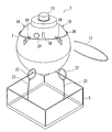
- FIG. 1 is a schematic diagram of an example of an embodiment of an observation device in which the fixed release device of the present invention is mounted
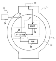
- FIG. 2 is a block diagram showing an internal configuration of the observation device of the embodiment of FIG.
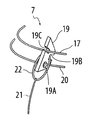
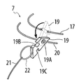
- FIG. 3 is a schematic enlarged view showing an enlarged region denoted by reference sign A in FIG. 1, and
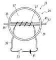
- FIG. 4 conceptually shows a fusing device provided in the trigger mechanism of the observation device of the present embodiment.
- FIG. 5 is a diagram illustrating a state after the trigger mechanism of the coupling device illustrated in FIG. 3 is operated
- FIG. 6 is an observation device according to the present embodiment after the trigger mechanism is operated.
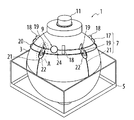
- the observation device 1 shown in FIG. 1 is an ocean bottom seismometer (OBS) that is installed on the ocean floor and performs measurement.
- the observation device 1 includes a measuring device such as a seismometer, an observation device body 3 (buoyancy body) having buoyancy, an anchor 5 (weight) for suspending the observation device body 3 on the seabed, and observation. It is comprised from the connection apparatus 7 which connects the apparatus main body 3 and the anchor 5, the trigger mechanism 9, and the transducer 11 (reception part) for receiving the trigger signal for making the trigger mechanism 9 into an operation state.
- the observation device main body 3 is composed of a glass ball 13 that can withstand water pressure and protect the built-in device from being flooded, and a hard hat 15 that protects the glass ball 13.
- a component for operating a fusing device 23 of the trigger mechanism 9 described later is built in the glass bulb 13. Since the observation instrument body 3 having the glass bulb 13 as a pressure vessel is made lighter than the weight of water corresponding to the drainage volume, the observation instrument body 3 has buoyancy in water.
- the anchor 5 is a heavy object made of metal or the like, and although not shown, a plurality of mounting brackets for attaching a connecting member 21 described later are fixed to the anchor 5.
- FIG. 3 is a schematic enlarged view showing the region denoted by reference symbol A in FIG. 1 in an enlarged manner, and shows a part of the connecting device 7 in a state where the observation device main body 3 and the anchor 5 are connected. However, the observation apparatus main body 3 is omitted.
- the connecting device 7 of the present embodiment includes a closed loop member 17, three rotating arms 19 (locking mechanisms) attached to a closed loop shaft member 20 provided along the outer periphery of the hard hat 15, and elasticity. Or three connecting members 21 made of a string-like member that can be adjusted and tightened by appropriately setting the length.
- the connecting member 21 has a structure in which a locking ring 22 is provided at one end and the other end is fixed to a mounting bracket (not shown) provided on the anchor 5.
- the three connecting members 21 are arranged around the hard hat 15 at equal intervals. In FIG. 1, two of the three connecting members 21 are arranged so as to be visible, and the remaining one is arranged at a position hidden by the observation apparatus main body 3.
- the closed loop member 17 surrounds a plurality of closed loop member mounting portions 18 that are installed around the top of the observation apparatus main body 3 at intervals in the circumferential direction, and a plurality of closed loop member mounting portions 18 are connected in order.
- the closed loop member mounting portion 18 is locked in a stretched state.
- the closed loop member 17 is provided with one fusing device 23 to be described later constituting the trigger mechanism 9.
- the closed loop member 17 is formed of a thermoplastic material such as nylon, and the portion where the fusing device 23 is provided constitutes the portion to be cut.
- each rotating arm 19 is rotated in a direction toward and away from the observation apparatus main body 3 with the closed loop shaft member 20 as a rotation center through the lower end region of each of the three rotation arms 19.
- a through-hole 19A for attachment is formed.
- each rotating arm 19 has a first locked portion 19 ⁇ / b> B in which a locking ring 22 is locked on a side portion on the side of the observation device main body 3, and a side portion on the opposite side to the observation device main body 3.
- a second locked portion 19C to which the closed loop member 17 is locked is formed at a position outside the first locked portion 19B as viewed from the through hole 19A.
- the first and second locked portions 19 ⁇ / b> B and 19 ⁇ / b> C are configured by recesses that open in the thickness direction of the rotating arm 19 and open in the width direction of the rotating arm 19, respectively.
- the rotating arm 19 is attached so as not to move in the circumferential direction of the closed loop shaft member 20, but is attached in a state having a little play, and can be moved slightly in the left-right direction. .
- the closed loop member 17 is By engaging with the two locked portions 19C, the rotation arm 19 is restrained from rotating about the closed loop shaft member 20, and the connecting member 21 is fixed.
- a connecting structure is constituted by the rotating arm 19 and the closed loop shaft member 20, and a connecting device 7 is constituted by the connecting structure and the closed loop member 17.
- the observation instrument body 3 is fixed to the anchor 5 using the three rotating arms 19 and the three connecting members 21.
- the number and the number are arbitrary, and can be changed according to the strength to be fixed and the size of the observation apparatus main body 3.
- five rotating arms 19 and five connecting members 21 may be used.
- the trigger mechanism 9 is mainly composed of one or more fusing devices 23, and when the trigger mechanism 9 operates, the fusing device 23 melts the closed loop member 17 and releases the fixing of the rotating arm 19.
- the configuration of the fusing device 23 is conceptually shown in FIG. FIG. 2 shows a state where one fusing device 23 is incorporated in the observation device 1 of the present embodiment.
- the fusing device 23 includes a tube-like closed loop member storage portion 25 for allowing the closed loop member 17 to slide and an electric heater portion 27 wound around the outside of the closed loop member storage portion 25 in a coil shape. And a fusing device main body 24 including a case 29 for storing them, a power source 31 for supplying current to the electric heater unit 27, and a switch circuit 33 for flowing current from the power source 31 to the electric heater unit 27. Yes.
- the power supply 31 is constituted by a battery.
- the electric heater unit 27 and the power source 31 are electrically connected by a lead wire 35.
- the switch circuit 33 constitutes a part of the energization control unit.
- the closed loop member storage portion 25 and the electric heater portion 27 are stored in the case 29.
- the inside of the case 29 is filled with silicone rubber 37, and is processed so that the water pressure applied to the electric heater portion 27 is uniform and has a waterproof structure.
- the silicone rubber 37 is drawn as being transparent.
- the case 29 is provided with holes 39, 41 at opposing positions.
- One end of the closed loop member housing portion 25 is aligned with the hole 39 and the other end is aligned with the hole 41, and a passage through which the closed loop member 17 passes is provided in the case 29. Is formed inside.
- the power supply 31 and the switch circuit 33 (energization control unit) are provided outside the case 29, and in the present embodiment, as shown in FIG.
- the closed loop member storage portion 25 is formed of a thermoplastic material like the closed loop member 17 and is melted by the heat generated by the electric heater portion 27. Note that if the closed loop member storage portion 25 is formed of a thermoplastic material such as polypropylene having a melting point equal to or lower than the melting point of the thermoplastic material constituting the closed loop member 17, when the electric heater portion 27 generates heat, the closed loop member storage portion 25 is first. Then, the closed loop member 17 is blown out or almost simultaneously.
- a power supply control unit 32 including a power supply 31, a switch circuit 33 and a control unit 34 is incorporated, and the fusing device main body is connected by a lead wire 35 through an underwater connector 43 provided on the glass bulb 13. 24 is connected to constitute a fusing device 23.
- the switch circuit 33 When the transducer 11 receives the trigger signal, the switch circuit 33 is turned on by the control unit 34, current flows from the power source 31 to the electric heater unit 27, and the closed loop member housing in the fusing device main body 24 is generated by the heat generated by the electric heater unit 27. The closed loop member 17 passing through the portion 25 and the closed loop member storage portion 25 is melted.
- the observation apparatus main body 3 is arranged at a position where it is fixed to the anchor 5 (see FIG. 1). In the present embodiment, the observation equipment main body 3 is disposed within the frame of the anchor 5.
- the closed loop member 17 in the open state before the closed loop is formed is disposed along the closed loop member mounting portion 18 installed outside the observation apparatus main body 3 and is passed through the closed loop member storage portion 25 of the fusing device main body 24. Then, the ends of the closed loop member 17 in the open state are joined to form a closed loop. Since the closed loop member 17 is accommodated in the closed loop member accommodating portion 25 in a slidable state, it is possible to adjust the length of the closed loop member 17 so as not to sag.
- the rotating arm 19 is rotated so that the first locked portion 19B is positioned on the observation device main body 3 side, and the rotating arm 19 is turned under the closed loop member 17 using play. Then, the closed loop member 17 is locked to the second locked portion 19C (state shown in FIG. 3). In this state, the locking ring 22 is locked to the first locked portion 19B, and a force is applied in the rotating direction of the rotating arm 19 by the tension of the connecting member 21, but the closed loop member The rotation arm 19 is restrained by 17 so as not to rotate. This operation is similarly performed for all the rotating arms 19 and the connecting members 21.
- the observation device body 3 is fixed to the anchor 5 by the above procedure.
- a submarine seismometer when it is finally ready, it is transported to a measurement point by ship, and a submarine seismometer is thrown from the sea surface and installed on the seabed.
- a trigger signal is transmitted.
- the trigger signal is transmitted by a wireless transmitter from the sea or the ground, for example.
- the energization control unit returns the switch circuit 33 that allows current to flow from the power source 31 to the electric heater unit 27 to the OFF state.
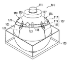
- FIG. 7 is a diagram of an observation device according to the second embodiment.
- the trigger mechanism 109 provided in the closed loop member 117 includes two fusing devices 123 and 123 '.
- the fusing device 123 ′ shares the power supply 131 and the power supply control unit 132 of the fusing device 123.
- two or more fusing devices are provided in this way, for example, even if the electric heater portion of one fusing device 123 breaks down due to disconnection or the like, if another fusing device 123 ′ is activated, the closed loop member 117. Can be melted, and the observation instrument body 103 can be reliably recovered.
- the fixing / releasing device of the present invention can be used even underwater or underwater.
- a weight installed on the ground and a balloon (buoyant body) are connected by a similar connecting device, and the balloon is released by transmitting a trigger signal from a remote location. It is possible to skip.
- the fixed release device of the present invention connects the buoyancy body and the weight by the connection device including the closed loop member, and can release the buoyancy body by fusing the closed loop member by the trigger mechanism. it can. Therefore, it is possible to securely fix the buoyant body and the weight with a simple structure and to easily release the fixed state. Moreover, since the closed loop member is used, it is possible to secure an installation space for other components at the top of the buoyancy body.
Landscapes
- Engineering & Computer Science (AREA)
- Life Sciences & Earth Sciences (AREA)
- Physics & Mathematics (AREA)
- Remote Sensing (AREA)
- Acoustics & Sound (AREA)
- Ocean & Marine Engineering (AREA)
- Mechanical Engineering (AREA)
- Combustion & Propulsion (AREA)
- Chemical & Material Sciences (AREA)
- Environmental & Geological Engineering (AREA)
- Geology (AREA)
- General Life Sciences & Earth Sciences (AREA)
- General Physics & Mathematics (AREA)
- Geophysics (AREA)
- Testing Or Calibration Of Command Recording Devices (AREA)
- Geophysics And Detection Of Objects (AREA)
Abstract
簡易な構造で浮力体と錘とを確実に固定し、且つ、容易に固定状態を解放することが可能な固定解放装置を提供する。本発明の固定解放装置(観測機器)1は、浮力体(観測機器本体)3と錘(アンカー)5と、これらを連結する連結装置7とからなる。連結装置7は、閉ループ部材17と、回動アーム19及び連結部材21からなる連結構造を有している。回動アーム19に連結部材21が係止され、閉ループ部材17が回動アーム19の回動を拘束することで、浮力体3が固定されている。浮力体3を解放する場合には、閉ループ部材17に備えられたトリガ機構9を作動させて閉ループ部材17を溶断する。すると、回動アーム19が回動し、連結部材21が抜けて浮力体3が解放される。
Description
本発明は、切離機構によって浮力体と錘との連結を解除する固定解放装置に関するものである。
従来より、連結装置で連結された浮力体と錘とからなり、切離機構によって浮力体と錘との連結を解除する固定解放装置が知られている。例えば、海底に沈めて地震の調査を行うため、海底に設置して計測を行う海底地震計(OBS[Ocean Bottom Seismograph])がある。海底における地震の発生メカニズム等を調査するために行われる屈折法地震探査では、人工的な地震波を発生させ、海底下の各地層の境界面で屈折した音波を所定の距離をあけて海底に設置された多数の海底地震計で受振し、測定を行う。このようにして用いられる海底地震計は、センサ等を内蔵した浮力体である海底地震計本体と、海底地震計本体を海底に係留するために、浮力体の下側に配置されるアンカー(錘)とが連結されて水底に沈められており、測定後は、データの回収・機器の保守等の目的で、海底地震計の本体部分の回収作業が行われる。回収作業は、浮力体と錘とを連結している連結装置に備えられた切離機構を作動させて行う。
切離機構としては、浮力体と錘とを連結するケーブルを切断刃によって切断するための動力を火薬の爆発を利用して発生する火薬方式[特開平8-271291号(特許文献1)]、浮力体と錘とを連結する金属板(例えば、ステンレス板)または金属線を強制的に電蝕させて切断することにより、浮力体と錘とを切り離す電蝕方式[特開2006-30124号(特許文献2)]等の方法がある。
しかしながら、火薬方式の場合には、切離機構を動かすための構造が複雑で大掛かりとなるため、切離機構の重量が重く、また、容積も大きくなるという問題があった。
また、電蝕方式の場合には、金属板または金属線を強制的に電蝕させて切断するまでに数分から十数分の時間を要するという問題があった。また、海底に長期間設置した場合には、金属板または金属線が自然腐蝕したり、皮膜を形成してしまうことがあり、正常に動作しなくなることがあった。さらに、強制的に電蝕させる方式は、淡水中では用いることができないという問題もあった。
本発明の目的は、浮力体と錘とを確実に固定し、且つ、容易に固定状態を解放状態にすることが可能な固定解放装置を提供することにある。
本発明の他の目的は、浮力体の頂部に他の部品の設置スペースを確保することが可能な固定解放装置を提供することにある。
本発明のさらに他の目的は、長期間、海底に設置しておいても動作可能な固定解放装置を提供することにある。
本発明の固定解放装置は、浮力体と浮力体の下側に配置される錘とを切り離し可能に連結する連結装置を備えている。連結装置は、トリガ信号により動作状態になると、浮力体と錘との連結を解除するトリガ機構を備えている。連結装置は、熱可塑性材料によって形成された1以上の被溶断部分を備えた閉ループ部材と、閉ループ部材と錘との間に配置され、閉ループ部材が閉状態にあるときには、浮力体を拘束し、閉ループ部材が開状態になると浮力体の拘束を解除するように構成された連結構造とを備えている。そして、トリガ機構が、動作状態になると、閉ループ部材の被溶断部分を溶断して閉ループ部材を開状態にする1以上の溶断装置を含んでいる。
このように、本発明の固定解放装置では、閉ループ部材を用いて連結構造を浮力体を拘束する状態と、浮力体の拘束を解除する状態とを作ることで、浮力体と錘の固定と解放を制御する。1以上の被溶断部を備えた閉ループ部材を連結装置に用いると、閉ループ部材と連結構造とを連結する際に、両者の連結位置が制限されないため、連結構造の構成を任意のものとすることが可能である。したがって、例えば、閉ループ部材と錘とを2本以上の紐状の連結部材を用いる連結構造で任意の箇所で連結したり、シート状または網状の連結部材を用いる連結構造で連結することもでき、浮力体を任意の連結構造を用いて簡単に且つ確実に拘束することができる。特に、閉ループ部材を錘とは逆側の浮力体の頂部を囲むように配置すると、浮力体の頂部の位置にスペースが空くことになるため、固定解放装置を構成する部品で、外部に設置する必要がある部品を配置する位置を浮力体の頂部に確保することが可能になる。例えば、固定解放装置が海底地震計の場合には、浮力体の頂部にトリガ信号を受信するための受信機(トランスデューサ)を配置することができる。さらに、トリガ機構によって閉ループ部材の1以上の被溶断部分を溶断することで閉ループ部材が開状態となることにより浮力体の拘束が解除されることから、拘束解除のために複雑な機構も必要なく、また、短時間(数秒)で浮力体と錘との切り離しが可能である。
さらには、閉ループ部材は金属ではないことから、腐蝕が発生しないため、長期間、水中に設置しておいた後でも、確実に浮力体と錘との切り離しが可能である。
なお、被溶断部分と溶断装置はそれぞれ1つでも十分であるが、被溶断部分と溶断装置をそれぞれ複数設けた場合には、少なくとも1つの溶断装置が動作して閉ループ部材の少なくとも1つの被溶断部分を溶断すれば、連結装置を確実に連結解除状態にすることができるので、固定解放装置の冗長性を担保することができる。例えば、固定解放装置が海底地震計に用いられる場合には、所定の期間における測定後にトリガ機構を動作させて浮力体に内蔵された測定機器を回収する際に、閉ループ部材に複数箇所の被溶断部分と複数個の溶断装置を設置しておけば、少なくとも1つの溶断装置が動作すれば、他の溶断装置が何らかの原因で動作しなかったとしても、浮力体を浮上させることができて、測定機器を確実に回収することが可能になる。
閉ループ部材が、浮力体の頂部を囲むように配置される場合において、連結構造の構成は任意である。例えば、連結構造を複数の連結部材と、複数の係止機構とを備える構成としてもよい。この場合、複数の連結部材は、一端が錘に固定され他端に係止部を備えて浮力体の周方向に間隔を開けて配置する。そして複数の係止機構は、閉ループ部材が閉状態にあるときに複数の連結部材に加わる張力を利用して複数の連結部材の複数の係止部と閉ループ部材とを係止状態に保持し、閉ループ部材が開状態になると、浮力体から複数の連結部材に加わる力(浮力体が浮力により上昇する際に連結部材に加わる力)を利用して複数の連結部材の複数の係止部と閉ループ部材との係止状態を解除するように構成する。「複数の連結部材に加わる張力」は、連結部材の長さを適宜に設定することにより調整することができる。このように複数の連結部材に加わる力を利用して係止部と閉ループ部材との係止状態の保持と解除を行うと、閉ループ部材が開状態となるだけで、簡単且つ確実に係止部と閉ループ部材との係止状態の解除を実現して、浮力体を確実に解放することができる。
具体的には、連結部材の係止部を係止リングとすることができる。係止機構は、回動中心を中心にして浮力体に近づく方向と離れる方向に回動する回動アームを備え、回動アームの浮力体側の側部には係止リングが係止される第1の被係止部が設けられ、回動アームの浮力体とは反対側の側部には回動中心から見て第1の被係止部よりも外側の位置に閉ループ部材が係止される第2の被係止部が設けられた構造を有するようにしてもよい。そして複数の連結部材は、係止リングが第1の被係止部に係止され且つ閉ループ部材が第2の被係止部に係止された状態で、回動アームを回動中心を中心して浮力体から離れる方向に回動させる力を発生するように寸法が定められている。このように構成すると、回動アームの第1の被係止部に係止リングが係止された状態では、回動アームには回動中心を中心にして浮力体から離れる方向に係止リングから力が加わっている。この状態で、回動アームの第2の被係止部に閉ループ部材が係止されると、閉ループ部材は回動アームが回動中心を中心して浮力体から離れる方向に回動することを阻止する。この状態は、閉ループ部材が閉状態を維持している限り継続する。溶断装置が動作して閉ループ部材の被溶断部が溶断されて閉ループ部材が開状態になると、閉ループ部材が回動アームの回動を阻止する機能を発揮できなくなる。その結果、連結部材から加わる張力が解放され且つ浮力体が浮力により上昇することにより、回動アームは浮力体から離れる方向に回動し、連結部材による浮力体の拘束が解除される。したがって、この構成を採用すれば、浮力体と錘との連結が容易で、且つ、簡単な構造で浮力体を容易に解放することができる。
係止機構は、閉ループ部材よりも錘側に配置されて回動中心を構成する閉ループ状軸部材を備えているのが好ましい。この場合、回動アームには、閉ループ状軸部材が貫通する貫通孔が形成されている。係止機構がこのような構造を備えていると、連結部材の本数に応じた数の回動アームを簡単に準備できる上、連結部材の位置に応じて回動アームの位置を簡単に変えることができるので、連結構造の組み立て作業が容易になる。
トリガ機構を構成する溶断装置は、閉ループ部材の被溶断部分に熱が伝達することを許容し且つ閉ループ部材の少なくとも一部をスライド可能に収納する閉ループ部材収納部と、閉ループ部材収納部の外側に配置されて閉ループ部材収納部を介して閉ループ部材の被溶断部分を加熱する電気ヒータ部と、電気ヒータ部に電流を供給するための電源と、トリガ機構が動作状態になると、電源から電気ヒータ部へ電流を流すスイッチ回路を含む通電制御部とから構成することができる。このような溶断装置を用いれば、閉ループ部材収納部が閉ループ部材をスライド可能な状態で収納しているため、浮力体と錘とを固定する際に、閉ループ部材の長さ調整やたるみが発生しないように調製が可能である。また、閉ループ部材の被溶断部分を溶断することによって、溶断した閉ループ部材が閉ループ部材収納部からスムーズに抜け出るため、閉ループ部材を確実に開状態とすることができる。さらに、前述のように、本発明では、溶断装置を1以上備えることが可能であり、この溶断装置を複数備えた場合でも、閉ループ部材を確実に開状態とすることができる。
以下、図面を参照して、本発明の固定解放装置の実施の形態について説明する。図1は、本発明の固定解放装置を実装した観測機器の実施の形態の一例の概略図であり、図2は、図1の実施の形態の観測機器の内部構成を示すブロック図であり、図3は、図1の符号Aを付した領域を拡大して示した概略拡大図であり、図4は、本実施の形態の観測機器のトリガ機構に備えられている溶断装置を概念的に示す図であり、図5は図3に示した連結装置のトリガ機構を動作させた後の様子を示す図であり、図6は、トリガ機構を作動させた後の本実施の形態の観測機器の状態を示す図である。
<観測機器>
図1に示した観測機器1は、海底に設置して測定を行う海底地震計(OBS)である。観測機器1は、地震計等の測定装置等を内蔵し、浮力を有する観測機器本体3(浮力体)と、観測機器本体3を海底に沈めて係留するためのアンカー5(錘)と、観測機器本体3とアンカー5とを連結する連結装置7と、トリガ機構9と、トリガ機構9を動作状態にするためのトリガ信号を受信するためのトランスデューサ11(受信部)とから構成されている。
図1に示した観測機器1は、海底に設置して測定を行う海底地震計(OBS)である。観測機器1は、地震計等の測定装置等を内蔵し、浮力を有する観測機器本体3(浮力体)と、観測機器本体3を海底に沈めて係留するためのアンカー5(錘)と、観測機器本体3とアンカー5とを連結する連結装置7と、トリガ機構9と、トリガ機構9を動作状態にするためのトリガ信号を受信するためのトランスデューサ11(受信部)とから構成されている。
観測機器本体3は、図2に示すように、水圧に耐え、内蔵する機器を浸水から守るためのガラス球13と、ガラス球13を保護するハードハット15とから構成されている。ガラス球13の内部には、図示しない測定装置に加えて、後述のトリガ機構9の溶断装置23を作動させるための構成要素が内蔵されている。ガラス球13を耐圧容器とする観測機器本体3は、排水体積相当の水の重量より軽く作られているため、観測機器本体3は水中において浮力を有している。アンカー5は、金属等により構成された重量物であり、図示していないが、アンカー5には、後述する連結部材21を取り付けるための複数の取付金具が固定されている。
<連結装置>
図3は、図1の符号Aを付した領域を拡大して示した概略拡大図であり、観測機器本体3とアンカー5とを連結した状態の連結装置7の一部を示してある。ただし、観測機器本体3は省略してある。
図3は、図1の符号Aを付した領域を拡大して示した概略拡大図であり、観測機器本体3とアンカー5とを連結した状態の連結装置7の一部を示してある。ただし、観測機器本体3は省略してある。
本実施の形態の連結装置7は、閉ループ部材17と、ハードハット15の外周に沿って設けられた閉ループ状軸部材20に取り付けられた3つの回動アーム19(係止機構)と、伸縮性を有する、または、長さを適宜に設定することにより調節し締め込み可能な紐状の部材からなる3本の連結部材21から構成されている。連結部材21は、一端に係止リング22を備え、他端がアンカー5に設けた図示しない取付金具に固定される構造になっている。3本の連結部材21は、ハードハット15の周囲に等間隔をあけて配置されている。なお、図1では、3本の連結部材21のうち、2本が見えるように配置されており、残りの1本は、観測機器本体3に隠れる位置に配置されている。
閉ループ部材17は、観測機器本体3の頂部の周辺に周方向に間隔を置いて設置された複数の閉ループ部材取付部18を囲んで且つ複数の閉ループ部材取付部18を順番につなぐように複数の閉ループ部材取付部18に伸ばされた状態で係止されている。また、閉ループ部材17には、トリガ機構9を構成する後述の溶断装置23が1つ取り付けられている。なお、本実施の形態では、閉ループ部材17は、ナイロン等の熱可塑性材料によって形成されており、溶断装置23が設けられた部分が被溶断部分を構成することになる。
3つの回動アーム19の下端部領域には、それぞれ閉ループ状軸部材20を通して、閉ループ状軸部材20を回動中心にして回動アーム19を観測機器本体3に近づく方向と離れる方向に回動可能に取り付けるための貫通孔19Aが形成されている。また、各回動アーム19には、観測機器本体3の側の側部に、係止リング22が係止される第1の被係止部19Bと、観測機器本体3とは反対側の側部に貫通孔19Aから見て第1の被係止部19Bよりも外側の位置に、閉ループ部材17が係止される第2の被係止部19Cとが形成されている。第1及び第2の被係止部19B及び19Cは、それぞれ、回動アーム19の厚み方向に開口し且つ回動アーム19の幅方向に開口する凹部によって構成されている。回動アーム19は、閉ループ状軸部材20の周方向に移動しないように取り付けられているが、少し遊びを有する状態で取り付けられており、左右方向にも少し動かすことができる状態になっている。
3本の連結部材21の係止リング22を、それぞれ対応する3つの回動アーム19に嵌めて係止リング22を第1の被係止部19Bに係止した状態で、閉ループ部材17を第2の被係止部19Cにそれぞれ係止することで、回動アーム19が閉ループ状軸部材20を中心として回動しないように拘束され、連結部材21が固定される。
なお、本実施の形態では、回動アーム19と閉ループ状軸部材20とにより連結構造が構成され、この連結構造と閉ループ部材17とにより連結装置7が構成されている。また、本実施の形態では、一例として3つの回動アーム19及び3本の連結部材21を用いて観測機器本体3をアンカー5に固定しているが、観測機器本体3をアンカー5に固定できれば個数・本数は任意であり、固定する強度や観測機器本体3の大きさにしたがって、変更することが可能である。例えば、5つの回動アーム19及び5本の連結部材21を用いてもよいのはもちろんである。さらに、3つの回動アーム19のそれぞれに対して、2本の連結部材21を用いる(すなわち、計6本の連結部材21を用いる)ように、異なる個数・本数を組み合わせることも可能である。
<トリガ機構>
トリガ機構9は、主に1以上の溶断装置23から構成されており、トリガ機構9が動作すると、溶断装置23が閉ループ部材17を溶断し、回動アーム19の固定を解除する。溶断装置23の構成は、図4に概念的に示す通りである。また、図2には、本実施の形態の観測機器1に1つの溶断装置23が組み込まれている状態を示してある。
トリガ機構9は、主に1以上の溶断装置23から構成されており、トリガ機構9が動作すると、溶断装置23が閉ループ部材17を溶断し、回動アーム19の固定を解除する。溶断装置23の構成は、図4に概念的に示す通りである。また、図2には、本実施の形態の観測機器1に1つの溶断装置23が組み込まれている状態を示してある。
図4に示すように、溶断装置23は、閉ループ部材17をスライド可能に通すためのチューブ状の閉ループ部材収納部25と、閉ループ部材収納部25の外側にコイル状に巻かれた電気ヒータ部27と、これらを収納するケース29とからなる溶断装置本体24と、電気ヒータ部27に電流を供給するための電源31と、電源31から電気ヒータ部27へ電流を流すスイッチ回路33とを備えている。電源31は電池により構成されている。電気ヒータ部27と電源31とは、リード線35で電気的に接続されている。図4において通電制御部は図示されていないが、図2に示すように、スイッチ回路33は、通電制御部の一部を構成している。本実施の形態では、閉ループ部材収納部25と電気ヒータ部27とがケース29の内部に収納されている。ケース29の内部には、シリコーンゴム37が充填されており、電気ヒータ部27にかかる水圧が均等になり、且つ、防水構造になるように加工されている。ただし、図4では、ケース29の内部構造を説明するために、シリコーンゴム37を透明なものとして描いている。ケース29には、対向する位置に孔39,41が設けられており、閉ループ部材収納部25の一端が孔39に、他端が孔41に合わせられて、閉ループ部材17が通る通路がケース29内に形成されている。電源31及びスイッチ回路33(通電制御部)は、ケース29の外に設けられており、本実施の形態では、図2に示すように、ガラス球13の内部に内蔵されている。
閉ループ部材収納部25は、閉ループ部材17と同様、熱可塑性材料によって形成されており、電気ヒータ部27の発熱により溶融するようになっている。なお、閉ループ部材収納部25を、閉ループ部材17を構成する熱可塑性材料の融点以下の融点を有するポリプロピレン等の熱可塑性材料により形成すれば、電気ヒータ部27が発熱すると、まず閉ループ部材収納部25が溶融し、その後、またはほぼ同時に、閉ループ部材17が溶断することになる。
ガラス球13の内部には、電源31並びにスイッチ回路33及び制御部34からなる通電制御部32が内蔵されており、ガラス球13に設けられた水中コネクタ43を介してリード線35で溶断装置本体24と接続されて、溶断装置23を構成している。
トランスデューサ11がトリガ信号を受信すると、制御部34によってスイッチ回路33がオン状態になり、電源31から電気ヒータ部27に電流が流れ、電気ヒータ部27の発熱により溶断装置本体24内の閉ループ部材収納部25及び閉ループ部材収納部25を通る閉ループ部材17を溶断する構造になっている。
<観測機器本体及びアンカーの固定>
観測機器本体3及びアンカー5を固定するまでの手順は次の通りである。
観測機器本体3及びアンカー5を固定するまでの手順は次の通りである。
(1)観測機器本体3をアンカー5に固定する位置に配置する(図1参照)。本実施の形態では、アンカー5の枠内に観測機器本体3を配置している。
(2)閉ループを形成する前の開状態の閉ループ部材17を、観測機器本体3の外側に設置された閉ループ部材取付部18に沿って配置し、溶断装置本体24の閉ループ部材収納部25に通した状態にしてから、開状態の閉ループ部材17の端部同士を結合して閉ループを形成する。閉ループ部材17が閉ループ部材収納部25にスライド可能な状態で収納されているため、閉ループ部材17の長さ調整やたるみが発生しないような調整が可能である。
(3)回動アーム19に、連結部材21の係止リング22を通す。
(4)第1の被係止部19Bが観測機器本体3の側に位置するように回動アーム19を回動させ、遊びを利用して回動アーム19を閉ループ部材17の下に回り込ませてから、第2の被係止部19Cに閉ループ部材17を係止させる(図3に示す状態)。この状態で、係止リング22が第1の被係止部19Bに係止されており、連結部材21の張力によって、回動アーム19が回動する方向に力が加わっているが、閉ループ部材17によって回動アーム19が回動しないように拘束されている。この作業は、全ての回動アーム19及び連結部材21について同様に行う。
上記手順によって、観測機器本体3をアンカー5に対して固定した状態にする。海底地震計の場合には、最終的に準備が整ったところで、船舶で計測地点まで運搬し、海面から海底地震計を投げ入れて海底に設置する。
<トリガ機構を作動させた状態>
測定が終了した場合や、測定機器のメンテナンス等のために、観測機器本体3を回収する場合には、次の手順でトリガ機構9の溶断装置23を作動させ、観測機器本体3をアンカー5から解放する。
測定が終了した場合や、測定機器のメンテナンス等のために、観測機器本体3を回収する場合には、次の手順でトリガ機構9の溶断装置23を作動させ、観測機器本体3をアンカー5から解放する。
(1)トリガ信号を発信する。トリガ信号は、例えば、海上や地上から、無線の発信器によって発信する。
(2)トランスデューサ11がトリガ信号を受信すると、制御部34がスイッチ回路33をオン状態にする。
(3)電源31から電気ヒータ部27に直流電流が流れて、発生する熱によって、閉ループ部材収納部25及び閉ループ部材17が溶断される。
(4)閉ループ部材17が溶断されることによって、回動アーム19の拘束が解除され、回動アーム19が、連結部材21の張力によって観測機器本体3から離れる方向に回動する。そして、回動アーム19が回動することにより、係止リング22が回動アーム19から抜ける(図5)。
(5)観測機器本体3がアンカー5から解放され、観測機器本体3が浮上する(図6)。
(6)その後、観測機器本体3がアンカー5から解放されることにより起因する物理的な変化(たとえば、水圧、傾斜角度、加速度、経過時間などの変化)や、タイマの時限の計数の完了を基に通電制御部は、電源31から電気ヒータ部27へ電流を流すスイッチ回路33をオフ状態に戻す。
上記手順によって、トリガ信号を発信することによって、観測機器本体3を短時間で且つ確実に回収することが可能になる。
図7は、第2の実施の形態の観測機器の図である。図1乃至図4に示した実施の形態と同じ部材には、図1乃至図4に付した符号の数に100の数を加えた数の符号を付して説明を省略する。第2の実施の形態では、閉ループ部材117に備えられたトリガ機構109が2つの溶断装置123及び123’を備えている。なお、溶断装置123’は、溶断装置123の電源131及び通電制御部132を共用している。このように溶断装置を2つ以上備えていると、例えば、1つの溶断装置123の電気ヒータ部が断線等で故障してしまっても、別の溶断装置123’が作動すれば、閉ループ部材117を溶断することができ、観測機器本体103を確実に回収することができる。
本発明の固定解放装置は、水中・海中以外でも使用可能である。例えば、気象調査用のラジオゾンデの場合、地上に設置した錘と、気球(浮力体)とを同様の連結装置で連結しておき、遠隔からトリガ信号を送信することで、気球を解放して飛ばすことが考えられる。
以上のように、本発明の固定解放装置は、閉ループ部材を含む連結装置により浮力体と錘とを連結しており、トリガ機構により、閉ループ部材を溶断することにより、浮力体を解放することができる。したがって、簡易な構造で浮力体と錘とを確実に固定し、且つ、容易に固定状態を解放することが可能である。また、閉ループ部材を用いていることから、浮力体の頂部に他の部品の設置スペースを確保することが可能である。
1 観測機器
3 観測機器本体
5 アンカー
7 連結装置
9 トリガ機構
11 トランスデューサ
13 ガラス球
15 ハードハット
17 閉ループ部材
18 閉ループ部材取付部
19 回動アーム
19A 孔
19B 第1の被係止部
19C 第2の被係止部
20 閉ループ状軸部材
21 連結部材
22 係止リング
23 溶断装置
24 溶断装置本体
25 閉ループ部材収納部
27 電気ヒータ部
29 ケース
31 電源
32 通電制御部
33 スイッチ回路
34 制御部
35 リード線
37 シリコーンゴム
39,41 孔
43 水中コネクタ
3 観測機器本体
5 アンカー
7 連結装置
9 トリガ機構
11 トランスデューサ
13 ガラス球
15 ハードハット
17 閉ループ部材
18 閉ループ部材取付部
19 回動アーム
19A 孔
19B 第1の被係止部
19C 第2の被係止部
20 閉ループ状軸部材
21 連結部材
22 係止リング
23 溶断装置
24 溶断装置本体
25 閉ループ部材収納部
27 電気ヒータ部
29 ケース
31 電源
32 通電制御部
33 スイッチ回路
34 制御部
35 リード線
37 シリコーンゴム
39,41 孔
43 水中コネクタ
Claims (8)
- 浮力体と前記浮力体の下側に配置される錘とを切り離し可能に連結する連結装置を備え、前記連結装置が、トリガ信号により動作状態になると、前記浮力体と前記錘との連結を解除するトリガ機構を備えている固定解放装置であって、
前記連結装置は、熱可塑性材料によって形成された1以上の被溶断部分を備えた閉ループ部材と、前記閉ループ部材と前記錘との間に配置され、前記閉ループ部材が閉状態にあるときには、前記浮力体を拘束し、前記閉ループ部材が開状態になると前記浮力体の拘束を解除するように構成された連結構造とを備え、
前記トリガ機構は、前記動作状態になると、前記閉ループ部材の前記被溶断部分を溶断して前記閉ループ部材を前記開状態にする1以上の溶断装置を含んでおり、
前記閉ループ部材は、前記浮力体の頂部を囲むように配置され、
前記連結構造は、一端が前記錘に固定され他端に係止部を備えて前記浮力体の周方向に間隔を開けて配置された複数の連結部材と、前記閉ループ部材が前記閉状態にあるときに前記複数の連結部材に加わる張力を利用して前記複数の連結部材の複数の前記係止部と前記閉ループ部材とを係止状態に保持し、前記閉ループ部材が前記開状態になると、前記浮力体から前記複数の連結部材に加わる力を利用して前記複数の連結部材の前記複数の係止部と前記閉ループ部材との係止状態を解除するように構成された複数の係止機構とを備えており、
前記係止部は係止リングからなり、
前記係止機構は、回動中心を中心にして前記浮力体に近づく方向と離れる方向に回動する回動アームを備え、前記回動アームの前記浮力体側の側部には前記係止リングが係止される第1の被係止部が設けられ、前記回動アームの前記浮力体とは反対側の側部には前記回動中心から見て前記第1の被係止部よりも外側の位置に前記閉ループ部材が係止される第2の被係止部が設けられた構造を有し、
前記複数の連結部材は、前記係止リングが前記第1の被係止部に係止され且つ前記閉ループ部材が前記第2の被係止部に係止された状態で、前記回動アームを前記回動中心を中心として前記浮力体から離れる方向に回動させる力を発生するように寸法が定められており、
前記係止機構は、前記閉ループ部材よりも前記錘側に配置されて前記回動中心を構成する閉ループ状軸部材を備えており、
前記回動アームには、前記閉ループ状軸部材が貫通する貫通孔が形成されている固定解放装置。 - 浮力体と前記浮力体の下側に配置される錘とを切り離し可能に連結する連結装置を備え、前記連結装置が、トリガ信号により動作状態になると、前記浮力体と前記錘との連結を解除するトリガ機構を備えている固定解放装置であって、
前記連結装置は、熱可塑性材料によって形成された1以上の被溶断部分を備えた閉ループ部材と、前記閉ループ部材と前記錘との間に配置され、前記閉ループ部材が閉状態にあるときには、前記浮力体を拘束し、前記閉ループ部材が開状態になると前記浮力体の拘束を解除するように構成された連結構造とを備え、
前記トリガ機構は、前記動作状態になると、前記閉ループ部材の前記被溶断部分を溶断して前記閉ループ部材を前記開状態にする1以上の溶断装置を含んでいる固定解放装置。 - 前記閉ループ部材は、前記浮力体の頂部を囲むように配置され、
前記連結構造は、一端が前記錘に固定され他端に係止部を備えて前記浮力体の周方向に間隔を開けて配置された複数の連結部材と、前記閉ループ部材が前記閉状態にあるときに前記複数の連結部材に加わる張力を利用して前記複数の連結部材の複数の前記係止部と前記閉ループ部材とを係止状態に保持し、前記閉ループ部材が前記開状態になると、前記浮力体から前記複数の連結部材に加わる力を利用して前記複数の連結部材の前記複数の係止部と前記閉ループ部材との係止状態を解除するように構成された複数の係止機構とを備えている請求項2に記載の固定解放装置。 - 前記係止部は係止リングからなり、
前記係止機構は、回動中心を中心にして前記浮力体に近づく方向と離れる方向に回動する回動アームを備え、前記回動アームの前記浮力体側の側部には前記係止リングが係止される第1の被係止部が設けられ、前記回動アームの前記浮力体とは反対側の側部には前記回動中心から見て前記第1の被係止部よりも外側の位置に前記閉ループ部材が係止される第2の被係止部が設けられた構造を有し、
前記複数の連結部材は、前記係止リングが前記第1の被係止部に係止され且つ前記閉ループ部材が前記第2の被係止部に係止された状態で、前記回動アームを前記回動中心を中心として前記浮力体から離れる方向に回動させる力を発生するように寸法が定められている請求項3に記載の固定解放装置。 - 前記係止機構は、前記閉ループ部材よりも前記錘側に配置されて前記回動中心を構成する閉ループ状軸部材を備えており、
前記回動アームには、前記閉ループ状軸部材が貫通する貫通孔が形成されている請求項4に記載の固定解放装置。 - 前記溶断装置は、前記閉ループ部材の前記被溶断部分に熱が伝達することを許容し且つ前記閉ループ部材の少なくとも一部をスライド可能に収納する閉ループ部材収納部と、前記閉ループ部材収納部の外側に配置されて前記閉ループ部材収納部を介して前記閉ループ部材の前記被溶断部分を加熱する電気ヒータ部と、前記電気ヒータ部に電流を供給するための電源と、前記トリガ機構が前記動作状態になると、前記電源から前記電気ヒータ部へ電流を流すスイッチ回路を含む通電制御部とからなる請求項2に記載の固定解放装置。
- 請求項1乃至6のいずれか1項に記載の固定解放装置を備えて水底に設置される観測機器。
- 請求項1乃至6のいずれか1項に記載の固定解放装置を備えて海底に設置される海底地震計。
Priority Applications (1)
| Application Number | Priority Date | Filing Date | Title |
|---|---|---|---|
| US14/349,824 US9254892B2 (en) | 2011-10-06 | 2012-10-05 | Fixation releasing device |
Applications Claiming Priority (2)
| Application Number | Priority Date | Filing Date | Title |
|---|---|---|---|
| JP2011-221881 | 2011-10-06 | ||
| JP2011221881A JP5800296B2 (ja) | 2011-10-06 | 2011-10-06 | 固定解放装置 |
Publications (1)
| Publication Number | Publication Date |
|---|---|
| WO2013051720A1 true WO2013051720A1 (ja) | 2013-04-11 |
Family
ID=48043873
Family Applications (1)
| Application Number | Title | Priority Date | Filing Date |
|---|---|---|---|
| PCT/JP2012/076037 WO2013051720A1 (ja) | 2011-10-06 | 2012-10-05 | 固定解放装置 |
Country Status (3)
| Country | Link |
|---|---|
| US (1) | US9254892B2 (ja) |
| JP (1) | JP5800296B2 (ja) |
| WO (1) | WO2013051720A1 (ja) |
Cited By (4)
| Publication number | Priority date | Publication date | Assignee | Title |
|---|---|---|---|---|
| CN106956750A (zh) * | 2017-04-11 | 2017-07-18 | 北京工业大学 | 一种潜标的压载固定基座刚性锁定和快速脱离装置 |
| CN107479088A (zh) * | 2017-06-15 | 2017-12-15 | 中石化石油工程技术服务有限公司 | 一种闭环数字加速度检波器谐波失真系统及测试方法 |
| CN111137404A (zh) * | 2020-01-03 | 2020-05-12 | 屠斌伟 | 一种海洋探测装置回收的信标装置 |
| TWI824429B (zh) * | 2021-04-01 | 2023-12-01 | 國立研究開發法人海洋研究開發機構 | 鉛錘分離裝置 |
Families Citing this family (10)
| Publication number | Priority date | Publication date | Assignee | Title |
|---|---|---|---|---|
| KR101529511B1 (ko) * | 2014-02-06 | 2015-06-17 | 국방과학연구소 | 절단하중 조절이 가능한 dc 전원 제어형 수중 분리장치 |
| US9651374B1 (en) | 2014-04-07 | 2017-05-16 | The United States Of America As Represented By The Secretary Of The Navy | Method and system for measuring physical phenomena in an open water environment |
| CN105549072B (zh) * | 2016-02-03 | 2017-12-15 | 中国地震局地震预测研究所 | 强震宽频带地震计的开锁摆系统 |
| CN109425379A (zh) * | 2017-08-30 | 2019-03-05 | 深圳市灵联科技有限公司 | 物联网领域器皿开闭状态检测技术-瓶塞类 |
| US11122785B2 (en) | 2017-10-15 | 2021-09-21 | Crab Raft, Inc. | System and use method for untethered trap brought to surface by remote control |
| KR102159543B1 (ko) * | 2018-11-30 | 2020-09-24 | 조태성 | 부표 연결 구조 |
| CN111932978B (zh) * | 2020-08-19 | 2021-12-14 | 武汉交通职业学院 | 一种垂吊式试验平台 |
| CN113877099B (zh) * | 2021-09-24 | 2022-06-24 | 上海电信工程有限公司 | 一种用于初期火灾的灭火装置及通信基站 |
| CN114604366B (zh) * | 2022-05-16 | 2022-07-26 | 山东省科学院海洋仪器仪表研究所 | 自沉浮式剖面探测浮标导流壳自动脱落装置及导流壳 |
| CN116643316B (zh) * | 2023-05-30 | 2024-01-19 | 中国科学院地质与地球物理研究所 | 一种多功能可自由组合海底地震探测装置 |
Citations (3)
| Publication number | Priority date | Publication date | Assignee | Title |
|---|---|---|---|---|
| JPS63191918A (ja) * | 1987-02-04 | 1988-08-09 | Nec Corp | 海中探査ブイの深度切換紐切断方式 |
| JPH09196710A (ja) * | 1996-01-22 | 1997-07-31 | Oki Electric Ind Co Ltd | レリーサ及び該レリーサにおける切り離し方法 |
| JP2006030124A (ja) * | 2004-07-21 | 2006-02-02 | Nichiyu Giken Kogyo Co Ltd | 水中切離装置 |
Family Cites Families (1)
| Publication number | Priority date | Publication date | Assignee | Title |
|---|---|---|---|---|
| JP3523928B2 (ja) | 1995-03-29 | 2004-04-26 | 日油技研工業株式会社 | 水中観測機器固定具のケーブル切断機付分離装置 |
-
2011
- 2011-10-06 JP JP2011221881A patent/JP5800296B2/ja active Active
-
2012
- 2012-10-05 US US14/349,824 patent/US9254892B2/en not_active Expired - Fee Related
- 2012-10-05 WO PCT/JP2012/076037 patent/WO2013051720A1/ja active Application Filing
Patent Citations (3)
| Publication number | Priority date | Publication date | Assignee | Title |
|---|---|---|---|---|
| JPS63191918A (ja) * | 1987-02-04 | 1988-08-09 | Nec Corp | 海中探査ブイの深度切換紐切断方式 |
| JPH09196710A (ja) * | 1996-01-22 | 1997-07-31 | Oki Electric Ind Co Ltd | レリーサ及び該レリーサにおける切り離し方法 |
| JP2006030124A (ja) * | 2004-07-21 | 2006-02-02 | Nichiyu Giken Kogyo Co Ltd | 水中切離装置 |
Cited By (4)
| Publication number | Priority date | Publication date | Assignee | Title |
|---|---|---|---|---|
| CN106956750A (zh) * | 2017-04-11 | 2017-07-18 | 北京工业大学 | 一种潜标的压载固定基座刚性锁定和快速脱离装置 |
| CN107479088A (zh) * | 2017-06-15 | 2017-12-15 | 中石化石油工程技术服务有限公司 | 一种闭环数字加速度检波器谐波失真系统及测试方法 |
| CN111137404A (zh) * | 2020-01-03 | 2020-05-12 | 屠斌伟 | 一种海洋探测装置回收的信标装置 |
| TWI824429B (zh) * | 2021-04-01 | 2023-12-01 | 國立研究開發法人海洋研究開發機構 | 鉛錘分離裝置 |
Also Published As
| Publication number | Publication date |
|---|---|
| JP5800296B2 (ja) | 2015-10-28 |
| US20140315451A1 (en) | 2014-10-23 |
| US9254892B2 (en) | 2016-02-09 |
| JP2013082251A (ja) | 2013-05-09 |
Similar Documents
| Publication | Publication Date | Title |
|---|---|---|
| JP5800296B2 (ja) | 固定解放装置 | |
| JP2013082251A5 (ja) | ||
| JP6253026B2 (ja) | 水中観測機器 | |
| JP5812486B2 (ja) | 溶断装置 | |
| US8448592B2 (en) | External rescue and recovery devices and methods for underwater vehicles | |
| CN110520352B (zh) | 用于固定浸没式浮筒的系统 | |
| RU2759033C2 (ru) | Автономная локационная система летательного аппарата | |
| JP5923169B2 (ja) | 通信ブイおよび展開の方法 | |
| ES2362061T3 (es) | Baliza sumergida. | |
| US6612886B2 (en) | In-line cable retriever | |
| JP2015104934A (ja) | 水中音計測装置 | |
| US20220097867A1 (en) | Unmanned aerial vehicle launching capsule | |
| EP0360671A1 (fr) | Dispositif de sauvetage d'une personne tombée d'un véhicule nautique | |
| US9815532B2 (en) | Device for detecting dislogded anchoring apparatus and the like | |
| US7054230B1 (en) | Locator device for submerged structures | |
| KR102410574B1 (ko) | 해상 조난자 위치 추적 장치 | |
| JP3456529B2 (ja) | 管制型発音弾ブイ | |
| US3786404A (en) | Deep ocean transponder | |
| TW202239665A (zh) | 鉛錘分離裝置 | |
| GB2250592A (en) | Underwater acoustic sensing apparatus |
Legal Events
| Date | Code | Title | Description |
|---|---|---|---|
| 121 | Ep: the epo has been informed by wipo that ep was designated in this application |
Ref document number: 12838416 Country of ref document: EP Kind code of ref document: A1 |
|
| NENP | Non-entry into the national phase |
Ref country code: DE |
|
| WWE | Wipo information: entry into national phase |
Ref document number: 14349824 Country of ref document: US |
|
| 122 | Ep: pct application non-entry in european phase |
Ref document number: 12838416 Country of ref document: EP Kind code of ref document: A1 |