WO2013051696A1 - 転がり軸受 - Google Patents
転がり軸受 Download PDFInfo
- Publication number
- WO2013051696A1 WO2013051696A1 PCT/JP2012/075955 JP2012075955W WO2013051696A1 WO 2013051696 A1 WO2013051696 A1 WO 2013051696A1 JP 2012075955 W JP2012075955 W JP 2012075955W WO 2013051696 A1 WO2013051696 A1 WO 2013051696A1
- Authority
- WO
- WIPO (PCT)
- Prior art keywords
- cylindrical roller
- axial
- side surfaces
- rolling
- portions
- Prior art date
- Legal status (The legal status is an assumption and is not a legal conclusion. Google has not performed a legal analysis and makes no representation as to the accuracy of the status listed.)
- Ceased
Links
Images



Classifications
-
- F—MECHANICAL ENGINEERING; LIGHTING; HEATING; WEAPONS; BLASTING
- F16—ENGINEERING ELEMENTS AND UNITS; GENERAL MEASURES FOR PRODUCING AND MAINTAINING EFFECTIVE FUNCTIONING OF MACHINES OR INSTALLATIONS; THERMAL INSULATION IN GENERAL
- F16C—SHAFTS; FLEXIBLE SHAFTS; ELEMENTS OR CRANKSHAFT MECHANISMS; ROTARY BODIES OTHER THAN GEARING ELEMENTS; BEARINGS
- F16C33/00—Parts of bearings; Special methods for making bearings or parts thereof
- F16C33/30—Parts of ball or roller bearings
- F16C33/46—Cages for rollers or needles
- F16C33/467—Details of individual pockets, e.g. shape or roller retaining means
- F16C33/4676—Details of individual pockets, e.g. shape or roller retaining means of the stays separating adjacent cage pockets, e.g. guide means for the bearing-surface of the rollers
-
- F—MECHANICAL ENGINEERING; LIGHTING; HEATING; WEAPONS; BLASTING
- F16—ENGINEERING ELEMENTS AND UNITS; GENERAL MEASURES FOR PRODUCING AND MAINTAINING EFFECTIVE FUNCTIONING OF MACHINES OR INSTALLATIONS; THERMAL INSULATION IN GENERAL
- F16C—SHAFTS; FLEXIBLE SHAFTS; ELEMENTS OR CRANKSHAFT MECHANISMS; ROTARY BODIES OTHER THAN GEARING ELEMENTS; BEARINGS
- F16C33/00—Parts of bearings; Special methods for making bearings or parts thereof
- F16C33/30—Parts of ball or roller bearings
- F16C33/46—Cages for rollers or needles
- F16C33/4617—Massive or moulded cages having cage pockets surrounding the rollers, e.g. machined window cages
- F16C33/4623—Massive or moulded cages having cage pockets surrounding the rollers, e.g. machined window cages formed as one-piece cages, i.e. monoblock cages
- F16C33/4629—Massive or moulded cages having cage pockets surrounding the rollers, e.g. machined window cages formed as one-piece cages, i.e. monoblock cages made from metal, e.g. cast or machined window cages
-
- F—MECHANICAL ENGINEERING; LIGHTING; HEATING; WEAPONS; BLASTING
- F16—ENGINEERING ELEMENTS AND UNITS; GENERAL MEASURES FOR PRODUCING AND MAINTAINING EFFECTIVE FUNCTIONING OF MACHINES OR INSTALLATIONS; THERMAL INSULATION IN GENERAL
- F16C—SHAFTS; FLEXIBLE SHAFTS; ELEMENTS OR CRANKSHAFT MECHANISMS; ROTARY BODIES OTHER THAN GEARING ELEMENTS; BEARINGS
- F16C33/00—Parts of bearings; Special methods for making bearings or parts thereof
- F16C33/30—Parts of ball or roller bearings
- F16C33/46—Cages for rollers or needles
- F16C33/467—Details of individual pockets, e.g. shape or roller retaining means
- F16C33/4682—Details of individual pockets, e.g. shape or roller retaining means of the end walls, e.g. interaction with the end faces of the rollers
-
- F—MECHANICAL ENGINEERING; LIGHTING; HEATING; WEAPONS; BLASTING
- F16—ENGINEERING ELEMENTS AND UNITS; GENERAL MEASURES FOR PRODUCING AND MAINTAINING EFFECTIVE FUNCTIONING OF MACHINES OR INSTALLATIONS; THERMAL INSULATION IN GENERAL
- F16C—SHAFTS; FLEXIBLE SHAFTS; ELEMENTS OR CRANKSHAFT MECHANISMS; ROTARY BODIES OTHER THAN GEARING ELEMENTS; BEARINGS
- F16C19/00—Bearings with rolling contact, for exclusively rotary movement
- F16C19/22—Bearings with rolling contact, for exclusively rotary movement with bearing rollers essentially of the same size in one or more circular rows, e.g. needle bearings
- F16C19/24—Bearings with rolling contact, for exclusively rotary movement with bearing rollers essentially of the same size in one or more circular rows, e.g. needle bearings for radial load mainly
- F16C19/26—Bearings with rolling contact, for exclusively rotary movement with bearing rollers essentially of the same size in one or more circular rows, e.g. needle bearings for radial load mainly with a single row of rollers
-
- F—MECHANICAL ENGINEERING; LIGHTING; HEATING; WEAPONS; BLASTING
- F16—ENGINEERING ELEMENTS AND UNITS; GENERAL MEASURES FOR PRODUCING AND MAINTAINING EFFECTIVE FUNCTIONING OF MACHINES OR INSTALLATIONS; THERMAL INSULATION IN GENERAL
- F16C—SHAFTS; FLEXIBLE SHAFTS; ELEMENTS OR CRANKSHAFT MECHANISMS; ROTARY BODIES OTHER THAN GEARING ELEMENTS; BEARINGS
- F16C2240/00—Specified values or numerical ranges of parameters; Relations between them
- F16C2240/40—Linear dimensions, e.g. length, radius, thickness, gap
- F16C2240/50—Crowning, e.g. crowning height or crowning radius
Definitions
- the present invention relates to a rolling bearing provided with a cage.
- FIG. 5 shows a cage 110 used in a conventional cylindrical roller bearing and a cylindrical roller 104 accommodated in a pocket portion 111 of the cage 110.
- the retainer 110 includes a plurality of pillar portions arranged at predetermined intervals in the circumferential direction so as to connect the pair of annular portions 112, 112 arranged side by side in the axial direction and the pair of annular portions 112, 112. 116.
- a space surrounded by the pair of annular portions 112 and 112 and the two adjacent pillar portions 116 and 116 becomes the pocket portion 111.
- FIG. 5 shows a state where the cylindrical roller 104 is accommodated in only one pocket portion 111.
- edge load end concentrated load
- wear W may occur.
- seizure or peeling may occur.
- cylindrical roller bearings have been proposed in which the edge load is reduced by changing the shape of the cylindrical rollers and pockets (see, for example, Patent Document 1).
- a crowning portion 208 having a slight curvature is formed on the rolling surface 205 of the cylindrical roller 204.
- the pocket side surface 223 of the pocket portion 211 of the retainer 210 has a pocket gap larger than the curvature of the crowning portion 208 from the concave portion 229 provided in the axial central portion of the circumferential side surface 223 toward both axial sides.
- a concave arc portion 228 having a larger curvature is formed.
- the edge load can be reduced. Moreover, according to this structure, since the attitude
- the present invention has been made in view of the above circumstances, and its purpose is to reduce the edge load on the surface forming the pocket portion of the cage even when the skew of the rolling element occurs, and to wear the surface. It is to provide a rolling bearing capable of preventing seizure and peeling.
- the cage has a pair of annular portions arranged side by side in the axial direction, and a plurality of column portions arranged at predetermined intervals in the circumferential direction so as to connect the pair of annular portions,
- the pocket portion is formed by a surface facing in the axial direction of the pair of annular portions and a surface facing in the circumferential direction of two column portions adjacent in the circumferential direction,
- the rolling bearing of the present invention even when the rolling element skew occurs, it is possible to prevent the rolling surface of the rolling element from coming into extremely strong contact with the surface forming the pocket portion of the cage, thereby reducing the edge load. can do. Thereby, abrasion, seizure, and peeling of the surface forming the pocket portion can be prevented.
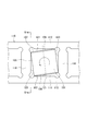
- FIG. 3 is a partial top view of the cage of FIG. 2. It is a figure for demonstrating the case where skew arises in the cylindrical roller in position embodiment of this invention. It is a partial top view of the retainer of the conventional cylindrical roller bearing.
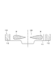
- FIG. 6 is a cross-sectional view taken along the line VV in FIG. 5. It is a partial top view of the cage of another conventional cylindrical roller bearing.
- FIG. 1 is a radial sectional view of a cylindrical roller bearing 1 according to an embodiment of the present invention.
- 2 shows an axial sectional view of the cage 10 of FIG. 1
- FIG. 3 shows a partial top view of the cage 10 of FIG.
- a cylindrical roller bearing 1 includes an outer ring 2 having an outer ring raceway surface 2a formed on an inner peripheral surface, an inner ring 3 having an inner ring raceway surface 3a formed on an outer peripheral surface, and a plurality of rolling elements.
- a cylindrical roller 4 and a cage 10 that is disposed between the outer ring 2 and the inner ring 3 and holds the plurality of cylindrical rollers 4 are provided.
- the cage 10 is a machined cage and has a circumferential shape so as to connect the pair of annular portions 12 and 12 arranged in the axial direction and the annular portions 12. And a plurality of pillar portions 16 arranged at predetermined intervals in the direction.
- the cage 10 includes a plurality of pocket portions 11 as a space surrounded by a pair of annular portions 12 and 12 and two adjacent pillar portions 16 and 16.
- the side surfaces facing in the axial direction of the pair of annular portions 12 and 12 forming the pocket portion 11 are referred to as axial side surfaces 21 and 21 and opposed in the circumferential direction of the two column portions 16 and 16 adjacent in the circumferential direction. These side surfaces are referred to as circumferential side surfaces 23, 23.
- one cylindrical roller 4 is held so as to roll freely.
- each of the circumferential side surfaces 23, 23 of the pocket portion 11 has a circumferential convex surface portion 28 that is convex toward the circumferential center of the pocket portion 11 in a direction away from the column portion 16. , Formed by crowning. That is, the circumferential convex curved surface portion 28 protrudes toward the cylindrical roller 4 and is convex. As a result, even when the cylindrical roller 4 is skewed as shown in FIG. 4, the contact pressure between the rolling surface 5 and the chamfered portion 7 of the cylindrical roller 4 and the circumferential side surface 23 is concentrated. It can suppress becoming excessive. Thereby, the edge load on the circumferential side surfaces 23 and 23 can be alleviated, and wear, seizure, peeling and the like on the circumferential side surfaces 23 and 23 can be prevented.
- the circumferentially convex curved surface portions 28 and 28 are formed by crowning on the circumferential side surfaces 23 and 23 forming the pocket portion 11 of the cage 10, and the shaft Axial convex curved surface portions 26 and 26 are formed on the direction side surfaces 21 and 21 by crowning.
- the present invention is not limited to the above-described embodiment, and can be changed or improved as appropriate.
- the cylindrical roller bearing 1 has been described in the above embodiment, the present invention can also be applied to a tapered roller bearing.
- basket in which the convex-curved surface part was formed by crowning was demonstrated with respect to all the axial direction side surfaces 21 and 21 and the opposing circumferential direction side surfaces 23 and 23, it is not restricted to this, Convex-curved surface portions may be formed only on any of the opposed axial side surfaces 21 and 21 and the opposed circumferential side surfaces 23 and 23.
- the punched cage is used as the cage 10.
- the cage 10 is not limited to this and may be a punched cage or the like.
Landscapes
- Engineering & Computer Science (AREA)
- General Engineering & Computer Science (AREA)
- Mechanical Engineering (AREA)
- Rolling Contact Bearings (AREA)
Abstract
Description
(1) 外周面に内輪軌道を有する内輪と、内周面に外輪軌道を有する外輪と、前記内輪軌道と前記外輪軌道との間に転動自在に設けられた複数の転動体と、前記複数の転動体を保持する複数のポケット部を有する保持器と、を備える転がり軸受であって、
前記保持器は、軸方向に並んで配置された一対の円環部と、前記一対の円環部を繋ぐように周方向に所定の間隔で配置される複数の柱部と、を有し、
前記ポケット部は、前記一対の円環部の軸方向で対向する面と、周方向に隣り合う2つの柱部の周方向で対向する面と、により形成され、
前記ポケット部を形成する面のうちの少なくとも一つの面がクラウニングによって前記転動体に対して凸曲面となるように形成されていることを特徴とする転がり軸受。
(2) 前記周方向に隣り合う2つの柱部の周方向で対向する面がクラウニングによって前記転動体に対して凸曲面となるように形成されている上記(1)記載の転がり軸受。
(3) 前記一対の円環部の軸方向で対向する面がクラウニングによって前記転動体に対して凸曲面となるように形成されている上記(1)または(2)記載の転がり軸受。
2 外輪
2a 外輪軌道面
3 内輪
3a 内輪軌道面
4 円筒ころ
10 保持器
11 ポケット部
12 円環部
16 柱部
21 軸方向側面
23 周方向側面
26 軸方向凸曲面部
28 周方向凸曲面部
Claims (3)
- 外周面に内輪軌道を有する内輪と、内周面に外輪軌道を有する外輪と、前記内輪軌道と前記外輪軌道との間に転動自在に設けられた複数の転動体と、前記複数の転動体を保持する複数のポケット部を有する保持器と、を備える転がり軸受であって、
前記保持器は、軸方向に並んで配置された一対の円環部と、前記一対の円環部を繋ぐように周方向に所定の間隔で配置される複数の柱部と、を有し、
前記ポケット部は、前記一対の円環部の軸方向で対向する面と、周方向に隣り合う2つの柱部の周方向で対向する面と、により形成され、
前記ポケット部を形成する面のうちの少なくとも一つの面がクラウニングによって前記転動体に対して凸曲面となるように形成されていることを特徴とする転がり軸受。 - 前記周方向に隣り合う2つの柱部の周方向で対向する面がクラウニングによって前記転動体に対して凸曲面となるように形成されている請求項1記載の転がり軸受。
- 前記一対の円環部の軸方向で対向する面がクラウニングによって前記転動体に対して凸曲面となるように形成されている請求項1または2記載の転がり軸受。
Priority Applications (2)
| Application Number | Priority Date | Filing Date | Title |
|---|---|---|---|
| CN2012800017726A CN103140689A (zh) | 2011-10-05 | 2012-10-05 | 滚动轴承 |
| US14/349,880 US20140254971A1 (en) | 2011-10-05 | 2012-10-05 | Rolling bearing |
Applications Claiming Priority (2)
| Application Number | Priority Date | Filing Date | Title |
|---|---|---|---|
| JP2011-221134 | 2011-10-05 | ||
| JP2011221134A JP2013079706A (ja) | 2011-10-05 | 2011-10-05 | 転がり軸受 |
Publications (1)
| Publication Number | Publication Date |
|---|---|
| WO2013051696A1 true WO2013051696A1 (ja) | 2013-04-11 |
Family
ID=48043849
Family Applications (1)
| Application Number | Title | Priority Date | Filing Date |
|---|---|---|---|
| PCT/JP2012/075955 Ceased WO2013051696A1 (ja) | 2011-10-05 | 2012-10-05 | 転がり軸受 |
Country Status (4)
| Country | Link |
|---|---|
| US (1) | US20140254971A1 (ja) |
| JP (1) | JP2013079706A (ja) |
| CN (1) | CN103140689A (ja) |
| WO (1) | WO2013051696A1 (ja) |
Families Citing this family (10)
| Publication number | Priority date | Publication date | Assignee | Title |
|---|---|---|---|---|
| DE102013226132B4 (de) * | 2013-12-16 | 2019-02-14 | Aktiebolaget Skf | Käfig für ein Wälzlager sowie Rollenlager mit einem Käfig |
| JP6331435B2 (ja) * | 2014-02-07 | 2018-05-30 | 株式会社ジェイテクト | 分割保持器及びころ軸受 |
| WO2015119088A1 (ja) * | 2014-02-07 | 2015-08-13 | 株式会社ジェイテクト | 分割保持器及びころ軸受 |
| JP2017044281A (ja) | 2015-08-27 | 2017-03-02 | Ntn株式会社 | 保持器及び円すいころ軸受 |
| DE102016218792A1 (de) * | 2015-10-28 | 2017-05-04 | Schaeffler Technologies AG & Co. KG | Axiallager sowie Achsschenkel-Lageranordnung und deren Verwendung |
| JP2017214965A (ja) * | 2016-05-31 | 2017-12-07 | Ntn株式会社 | ころ軸受 |
| CN111677760A (zh) * | 2020-06-28 | 2020-09-18 | 瓦房店轴承集团国家轴承工程技术研究中心有限公司 | 自润滑锁扣式三排圆柱轴承用隔离环 |
| US11365762B2 (en) * | 2020-11-16 | 2022-06-21 | Schaeffler Technologies AG & Co. KG | High speed bearing cage |
| JP7635652B2 (ja) | 2021-06-29 | 2025-02-26 | 日本精工株式会社 | 保持器及び円筒ころ軸受 |
| CN117889153B (zh) * | 2024-03-02 | 2024-07-30 | 华瑞传动科技(苏州)有限公司 | 一种转动轴承装置 |
Citations (3)
| Publication number | Priority date | Publication date | Assignee | Title |
|---|---|---|---|---|
| JPS5077747A (ja) * | 1973-10-09 | 1975-06-25 | ||
| US4403813A (en) * | 1981-10-14 | 1983-09-13 | The United States Of America As Represented By The Secretary Of The Air Force | Roller bearing cage design |
| JP2010091012A (ja) * | 2008-10-08 | 2010-04-22 | Nsk Ltd | 保持器付ころ軸受 |
Family Cites Families (17)
| Publication number | Priority date | Publication date | Assignee | Title |
|---|---|---|---|---|
| US2227064A (en) * | 1940-07-27 | 1940-12-31 | Shafer Bearing Corp | Antifriction bearing |
| US2418322A (en) * | 1944-03-16 | 1947-04-01 | Gen Motors Corp | Roller bearing |
| US2705176A (en) * | 1948-10-13 | 1955-03-29 | Skf Ind Inc | Sheet metal roller cage |
| NL78409C (ja) * | 1949-02-07 | 1900-01-01 | ||
| NL235328A (ja) * | 1958-01-22 | 1900-01-01 | ||
| JPS6084824U (ja) * | 1983-11-17 | 1985-06-11 | 日本精工株式会社 | ころ軸受用保持器 |
| US4605322A (en) * | 1983-11-30 | 1986-08-12 | The Torrington Company | Double row roller bearing retainer |
| DE8602881U1 (de) * | 1986-02-05 | 1986-03-13 | FAG Kugelfischer Georg Schäfer KGaA, 8720 Schweinfurt | Linearlagerkäfig |
| JPH07151154A (ja) * | 1993-11-30 | 1995-06-13 | Ntn Corp | 自動調心ころ軸受用保持器 |
| IT1293628B1 (it) * | 1997-07-18 | 1999-03-08 | Skf Ind Spa | Struttura di controllo di contenimento di corpi volventi di un cuscinetto a rotolamento, in particolare di un cuscinetto a rulli |
| JP2001012477A (ja) * | 1999-04-28 | 2001-01-16 | Nsk Ltd | 転がり軸受用保持器 |
| DE10165027C5 (de) * | 2000-10-27 | 2019-10-02 | Nsk Ltd. | Wälzlager und Spindelvorrichtung für Werkzeugmaschine |
| JP2002242938A (ja) * | 2001-02-16 | 2002-08-28 | Nsk Ltd | ころ軸受用保持器 |
| JP2004316757A (ja) * | 2003-04-15 | 2004-11-11 | Ntn Corp | 円筒ころ軸受および円筒ころ軸受用保持器 |
| DE102004026291A1 (de) * | 2004-05-28 | 2005-12-15 | Fag Kugelfischer Ag & Co. Ohg | Käfig mit Rollen |
| WO2006043444A1 (ja) * | 2004-10-22 | 2006-04-27 | Ntn Corporation | 円筒ころ軸受用もみ抜き保持器およびその製造方法 |
| JP4697006B2 (ja) * | 2006-03-30 | 2011-06-08 | 株式会社ジェイテクト | ころ軸受用保持器及び円錐ころ軸受 |
-
2011
- 2011-10-05 JP JP2011221134A patent/JP2013079706A/ja active Pending
-
2012
- 2012-10-05 WO PCT/JP2012/075955 patent/WO2013051696A1/ja not_active Ceased
- 2012-10-05 US US14/349,880 patent/US20140254971A1/en not_active Abandoned
- 2012-10-05 CN CN2012800017726A patent/CN103140689A/zh active Pending
Patent Citations (3)
| Publication number | Priority date | Publication date | Assignee | Title |
|---|---|---|---|---|
| JPS5077747A (ja) * | 1973-10-09 | 1975-06-25 | ||
| US4403813A (en) * | 1981-10-14 | 1983-09-13 | The United States Of America As Represented By The Secretary Of The Air Force | Roller bearing cage design |
| JP2010091012A (ja) * | 2008-10-08 | 2010-04-22 | Nsk Ltd | 保持器付ころ軸受 |
Also Published As
| Publication number | Publication date |
|---|---|
| US20140254971A1 (en) | 2014-09-11 |
| JP2013079706A (ja) | 2013-05-02 |
| CN103140689A (zh) | 2013-06-05 |
Similar Documents
| Publication | Publication Date | Title |
|---|---|---|
| JP2013079706A (ja) | 転がり軸受 | |
| US10054164B2 (en) | Rolling bearing | |
| US10047796B2 (en) | Rolling Bearing | |
| JP2012017770A (ja) | 自動調心ころ軸受 | |
| JP5928241B2 (ja) | 転がり軸受 | |
| JP2013015200A (ja) | 円すいころ軸受 | |
| JP6329198B2 (ja) | 円すいころ軸受 | |
| JP2012202453A (ja) | 自動調心ころ軸受 | |
| JP2015102144A (ja) | 自動調心ころ軸受 | |
| JP2021014871A (ja) | クロスローラ軸受 | |
| JP5050619B2 (ja) | 円すいころ軸受 | |
| JP6694288B2 (ja) | コロ軸受 | |
| JP6572754B2 (ja) | 転がり軸受 | |
| JP6829522B2 (ja) | 自動調心ころ軸受 | |
| WO2016194981A1 (ja) | 円すいころ軸受 | |
| JP2017078480A (ja) | 自動調心ころ軸受 | |
| JP2020159498A (ja) | クロスローラ軸受 | |
| JP6337482B2 (ja) | 自動調心ころ軸受 | |
| JP5218231B2 (ja) | 転がり軸受用保持器、並びにこれを備えた内輪組立体、外輪組立体、および転がり軸受 | |
| JP2014240672A (ja) | 軸受装置 | |
| JP2013015201A (ja) | 円すいころ軸受 | |
| JP7635652B2 (ja) | 保持器及び円筒ころ軸受 | |
| JP2010091012A (ja) | 保持器付ころ軸受 | |
| JP2009024762A (ja) | シェル形ころ軸受の嵌合構造 | |
| JP2016138604A (ja) | 円筒ころ軸受 |
Legal Events
| Date | Code | Title | Description |
|---|---|---|---|
| WWE | Wipo information: entry into national phase |
Ref document number: 201280001772.6 Country of ref document: CN |
|
| 121 | Ep: the epo has been informed by wipo that ep was designated in this application |
Ref document number: 12838894 Country of ref document: EP Kind code of ref document: A1 |
|
| WWE | Wipo information: entry into national phase |
Ref document number: 14349880 Country of ref document: US |
|
| NENP | Non-entry into the national phase |
Ref country code: DE |
|
| 122 | Ep: pct application non-entry in european phase |
Ref document number: 12838894 Country of ref document: EP Kind code of ref document: A1 |