WO2013047664A1 - 無線通信システム、移動端末装置、基地局装置および管理装置 - Google Patents
無線通信システム、移動端末装置、基地局装置および管理装置 Download PDFInfo
- Publication number
- WO2013047664A1 WO2013047664A1 PCT/JP2012/074900 JP2012074900W WO2013047664A1 WO 2013047664 A1 WO2013047664 A1 WO 2013047664A1 JP 2012074900 W JP2012074900 W JP 2012074900W WO 2013047664 A1 WO2013047664 A1 WO 2013047664A1
- Authority
- WO
- WIPO (PCT)
- Prior art keywords
- base station
- information
- enb
- mobile terminal
- management
- Prior art date
- Legal status (The legal status is an assumption and is not a legal conclusion. Google has not performed a legal analysis and makes no representation as to the accuracy of the status listed.)
- Ceased
Links
Images


Classifications
-
- H—ELECTRICITY
- H04—ELECTRIC COMMUNICATION TECHNIQUE
- H04W—WIRELESS COMMUNICATION NETWORKS
- H04W4/00—Services specially adapted for wireless communication networks; Facilities therefor
- H04W4/02—Services making use of location information
- H04W4/029—Location-based management or tracking services
-
- H—ELECTRICITY
- H04—ELECTRIC COMMUNICATION TECHNIQUE
- H04W—WIRELESS COMMUNICATION NETWORKS
- H04W4/00—Services specially adapted for wireless communication networks; Facilities therefor
- H04W4/02—Services making use of location information
-
- H—ELECTRICITY
- H04—ELECTRIC COMMUNICATION TECHNIQUE
- H04W—WIRELESS COMMUNICATION NETWORKS
- H04W64/00—Locating users or terminals or network equipment for network management purposes, e.g. mobility management
-
- H—ELECTRICITY
- H04—ELECTRIC COMMUNICATION TECHNIQUE
- H04W—WIRELESS COMMUNICATION NETWORKS
- H04W64/00—Locating users or terminals or network equipment for network management purposes, e.g. mobility management
- H04W64/003—Locating users or terminals or network equipment for network management purposes, e.g. mobility management locating network equipment
-
- H—ELECTRICITY
- H04—ELECTRIC COMMUNICATION TECHNIQUE
- H04B—TRANSMISSION
- H04B7/00—Radio transmission systems, i.e. using radiation field
- H04B7/14—Relay systems
- H04B7/15—Active relay systems
- H04B7/155—Ground-based stations
- H04B7/15507—Relay station based processing for cell extension or control of coverage area
-
- H—ELECTRICITY
- H04—ELECTRIC COMMUNICATION TECHNIQUE
- H04W—WIRELESS COMMUNICATION NETWORKS
- H04W84/00—Network topologies
- H04W84/005—Moving wireless networks
-
- H—ELECTRICITY
- H04—ELECTRIC COMMUNICATION TECHNIQUE
- H04W—WIRELESS COMMUNICATION NETWORKS
- H04W84/00—Network topologies
- H04W84/02—Hierarchically pre-organised networks, e.g. paging networks, cellular networks, WLAN [Wireless Local Area Network] or WLL [Wireless Local Loop]
- H04W84/04—Large scale networks; Deep hierarchical networks
- H04W84/042—Public Land Mobile systems, e.g. cellular systems
- H04W84/047—Public Land Mobile systems, e.g. cellular systems using dedicated repeater stations
Definitions
- the present invention relates to a wireless communication system that performs wireless communication between a mobile terminal device and a base station device, and a mobile terminal device, a base station device, and a management device provided therein, and more specifically, a movable base station device And a mobile terminal device, a base station device, and a management device provided in the wireless communication system.
- Non-Patent Document 2 (Chapter 4.3) and Non-Patent Document 3 (Chapter 4.3).
- a mobile base station device such as a femtocell base station (H (e) NB) or a mobile radio relay station (Mobile Relay (e) NB) is used to improve radio access performance.
- a mobile base station device such as a femtocell base station (H (e) NB) or a mobile radio relay station (Mobile Relay (e) NB) is used to improve radio access performance.
- H (e) NB femtocell base station
- Mobile Relay (e) NB Mobile Relay
- the position estimation method of the mobile terminal apparatus disclosed in Non-Patent Document 2 and Non-Patent Document 3 described above is based on the premise that the position where the base station apparatus exists is clear. Therefore, as described above, when a mobile base station apparatus exists and its position is not fixed, as disclosed in Non-Patent Document 4, it is difficult to estimate the position of the mobile terminal apparatus. Will occur.
- the location of the base station device is not clear, when a problem occurs in the wireless network, the location of the base station device cannot be specified, and it takes time to solve the above-mentioned problem. The above problem occurs.
- Non-Patent Document 5 and Patent Documents 1 to 3 disclose base station apparatus position estimation methods.
- a base station device is equipped with a mobile terminal device position estimation function using radio waves from other fixed base station devices, or a GNSS (Global Navigation Satellite System) function. Accordingly, it is disclosed that the position of the base station apparatus is estimated.
- GNSS Global Navigation Satellite System
- Patent Document 1 describes the position of a base station device when a mobile terminal device located in a specific femtocell can receive a signal from a GPS (Global Positioning System) satellite and detect other surrounding macrocells. A method of estimating is disclosed.
- Patent Documents 2 and 3 disclose a technique for estimating a femtocell that is currently located from past area information, triggered by an emergency call.
- 3GPP TS 23.271 v10.2.0 (2011-03) 3GPP TS36.305 v10.2.0 (2011-06) 3GPP TS25.305 v10.0.0 (2010-09) 3GPP TSG-RAN WG3 # 66bis 18-22 January 2010 Valencia, Spain R3-100342 3GPP TSG RAN WG3 # 71 Taiwan, 21-25 February 2011 R3-1110729
- Non-Patent Document 5 cannot be applied when the base station apparatus is installed in an area where GPS satellites or the like cannot be detected or an area where neighboring cells cannot be detected.
- Patent Document 1 cannot be applied when the mobile terminal device located in the area is located in an area where GPS satellites cannot be detected or an area where neighboring cells cannot be detected.
- Patent Document 2 and Patent Document 3 require an emergency call, and the location of the base station device cannot be estimated when there is no emergency call.
- the techniques disclosed in Patent Document 2 and Patent Document 3 are not intended to identify the position of the femtocell base station. Even using the techniques disclosed in Patent Document 2 and Patent Document 3, the position of the femtocell base station cannot be specified.
- An object of the present invention is to easily estimate the position of a base station apparatus when the base station apparatus is movable, and to easily estimate the position of a mobile terminal apparatus using the estimation result.
- a wireless communication system that can be used, and a mobile terminal device, a base station device, and a management device included in the wireless communication system.
- the wireless communication system of the present invention is a wireless communication system comprising a mobile terminal device that can move, a base station device that can wirelessly communicate with the mobile terminal device, and a management device, wherein the base station device is mobile And at least one of the mobile terminal device, the base station device, and the management device performs measurement and calculation for estimating base station position information that is information related to the position of the base station device, and A location estimation processing means for estimating base station location information, wherein the management device performs radio communication control in communication between the mobile terminal device and the base station device, control of a communication call, mobility management of the mobile terminal device, It is configured to perform at least one process of management of the wireless communication system and position information of devices constituting the wireless communication system, and the position estimation Based on the base station position information estimated by the use processing means, and performing the process.
- the mobile terminal device of the present invention is a wireless communication system comprising a mobile terminal device that can move, a base station device that can wirelessly communicate with the mobile terminal device, and a management device, wherein the management device is the mobile terminal.
- wireless communication control in communication between a device and the base station device, communication call control, mobility management of the mobile terminal device, management of the wireless communication system, and management of position information of devices constituting the wireless communication system
- a mobile terminal apparatus provided in a wireless communication system configured to perform at least one of the processing, and performing the processing based on the base station location information estimated by the location estimation processing means, the base station A position estimation processing means for performing measurement and calculation for estimating base station position information, which is information relating to the position of the apparatus, and the position estimation processing means Characterized in providing information obtained I to the management device or the base station apparatus.
- the base station apparatus of the present invention is a wireless communication system comprising a mobile terminal apparatus that can move, a base station apparatus that can wirelessly communicate with the mobile terminal apparatus, and a management apparatus, wherein the management apparatus is the mobile terminal.
- wireless communication control in communication between a device and the base station device, communication call control, mobility management of the mobile terminal device, management of the wireless communication system, and management of position information of devices constituting the wireless communication system
- a base station apparatus provided in a wireless communication system configured to perform at least one of the processing, and performing the processing based on the base station location information estimated by the location estimation processing means, wherein the base station device is movable Position estimation is performed for performing measurement and calculation for estimating base station position information, which is information related to the position of the base station apparatus, and estimating the base station position information. It comprises a use process means, characterized by providing said base station position information estimated by the position estimation processing unit to the management device.
- a management apparatus of the present invention is a management apparatus provided in a wireless communication system including a mobile terminal apparatus that can move, a base station apparatus that can wirelessly communicate with the mobile terminal apparatus, and a management apparatus, and the base station apparatus Wireless communication in communication between the mobile terminal apparatus and the base station apparatus, comprising: a position estimation processing means for performing calculation for estimating base station position information which is information related to the position of the base station and estimating the base station position information Configured to perform at least one of control, communication call control, mobility management of the mobile terminal device, management of the wireless communication system, and management of position information of the devices constituting the wireless communication system, The processing is performed based on the base station location information estimated by the location estimation processing means.
- the measurement and calculation for estimating the base station position information is performed by the position estimation processing means provided in at least one of the mobile terminal device, the base station device, and the management device.
- Base station position information is estimated.
- the base station position information is, for example, the position and moving speed of the base station device. Based on this base station position information, processing by the management device is performed.
- the base station apparatus when the base station apparatus is movable, the position of the base station apparatus can be easily estimated, and the position of the mobile terminal apparatus can be easily estimated using the estimation result.
- the position estimation processing means performs measurement and calculation for estimating the base station position information, and the base station position information is estimated and provided to the management apparatus.
- the management apparatus can easily estimate the position of the base station apparatus when the base station apparatus is movable, and can easily estimate the position of the mobile terminal apparatus using the estimation result. it can.
- the position estimation processing means performs measurement and calculation for estimating the base station position information of the own apparatus to estimate the base station position information of the own apparatus, and Given.
- the management apparatus can easily estimate the position of the base station apparatus when the base station apparatus is movable, and can easily estimate the position of the mobile terminal apparatus using the estimation result. it can.
- the position estimation processing means performs measurement and calculation for estimating the base station position information to estimate the base station position information, and performs processing based on the base station position information. Is done.
- the management apparatus can easily estimate the position of the base station apparatus when the base station apparatus is movable, and can easily estimate the position of the mobile terminal apparatus using the estimation result. it can.
- FIG. 1 is a block diagram showing an overall configuration of an LTE mobile communication system.
- FIG. It is explanatory drawing explaining the physical channel used with the mobile communication system of a LTE system. It is explanatory drawing explaining the transport channel used with the mobile communication system of a LTE system. It is explanatory drawing explaining the logical channel used with the mobile communication system of a LTE system.
- 1 is a block diagram showing a configuration of a mobile network system 200.
- FIG. 13 is a diagram showing an example of a sequence when the execution timing of the procedure between E-SMLC differs from FIG.
- FIG. 13 is a diagram showing an example of a sequence when the execution timing of the procedure between E-SMLC differs from FIG.
- It is a block diagram which shows the structure of UE in the 1st Embodiment of this invention. It is a block diagram which shows the structure of eNB_uu / s1 320 in the 1st Embodiment of this invention. It is a block diagram which shows the structure of eNB330 in the 1st Embodiment of this invention.
- FIG. It is a figure which shows an example of the sequence regarding the transmission process of the positional information between the radio
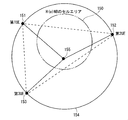
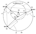
- FIG. It is a figure for demonstrating the method of position estimation. It is a figure for demonstrating the estimation method of the movement path
- the radio communication system is, for example, a mobile communication system.
- the W-CDMA system is a communication system defined by 3GPP (3rd Generation Partnership Project), which is a standardization organization for mobile communication systems, and standardized versions of the 10th release are compiled.
- 3GPP 3rd Generation Partnership Project
- LTE Long Term Evolution
- SAE System Architecture Evolution
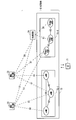
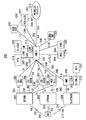
- FIG. 1 is a block diagram showing an overall configuration of an LTE mobile communication system (3GPP TS36.300 v10.3.0 (2010-03) (hereinafter referred to as “Non-Patent Document 6”)) 4.6. See Chapter 1).
- the mobile communication system includes a mobile terminal device (hereinafter may be referred to as “mobile terminal” or “user equipment (UE)”) 71 and a device having a base station function (hereinafter referred to as “base station device”). 72, an MME / S-GW unit 73, and a HeNBGW (Home-eNBeGateway) 74.
- Base station apparatus 72 and HeNBGW 74 constitute an evolved radio access network (EvolvedvolveUniversal Terrestrial Radio Access Network: E-UTRAN).
- E-UTRAN evolved radio access network
- the base station is referred to as an E-UTRAN NodeB, eNodeB, or eNB.
- the mobile terminal (UE) 71 can wirelessly communicate with the base station 72, and transmits and receives signals by wireless communication.
- the base station (E-UTRAN NodeB, eNodeB, eNB) 72 includes a macro cell eNB 72-1 and a local node Home-eNB 72-2.
- the eNB 72-1 has a relatively large large-scale coverage as a coverage that can be communicated with the mobile terminal (UE) 71.
- the Home-eNB 72-2 has a relatively small small-scale coverage.
- the MME / S-GW unit 73 includes one or both of a mobility management entity (Mobility Management Entity; abbreviated as MME) and a serving gateway (abbreviated as S-GW).
- MME Mobility Management Entity
- S-GW serving gateway
- the eNB 72-1 is connected to the MME unit 73 through the S1 interface, and control information is communicated between the eNB 72-1 and the MME unit 73.
- a plurality of MME units 73 may be connected to one eNB 72-1.
- the eNBs 72-1 are connected by the X2 interface, and control information is communicated between the eNBs 72-1.
- the Home-eNB 72-2 is connected to the MME unit 73 through the S1 interface, and control information is communicated between the Home-eNB 72-2 and the MME unit 73.
- a plurality of Home-eNBs 72-2 are connected to one MME unit 73.
- the Home-eNB 72-2 is connected to the MME unit 73 via the HeNBGW 74.
- the Home-eNB 72-2 and the HeNBGW 74 are connected by the S1 interface.
- the HeNBGW 74 and the MME unit 73 are connected by an S1 interface.
- One or more Home-eNBs 72-2 are connected to one HeNBGW 74, and information is communicated through the S1 interface.
- the HeNBGW 74 is connected to one or more MME units 73, and information is communicated through the S1 interface.
- the MME unit 73 and the HeNBGW 74 are higher-level node devices, and control connection between the eNB 72-1 and the Home-eNB 72-2 that are base stations and the mobile terminal (UE) 71.
- the X2 interface between Home-eNB 72-2 is supported. That is, the Home-eNB 72-2 is connected by the X2 interface, and control information is communicated between the Home-eNB 72-2. From the MME unit 73, the HeNBGW 74 appears as a Home-eNB 72-2. From the Home-eNB 72-2, the HeNBGW 74 appears as the MME unit 73.
- the Home-eNB 72-2 In both cases where the Home-eNB 72-2 is connected to the MME unit 73 via the HeNBGW 74, and the Home-eNB 72-2 is directly connected to the MME unit 73, the Home-eNB 72-2 and the MME unit 73 are connected.
- the HeNBGW 74 does not support mobility to the Home-eNB 72-2 or mobility from the Home-eNB 72-2 that spans a plurality of MME units 73.
- the Home-eNB 72-2 configures and supports a single cell.
- E-UTRAN supports relaying by having a relay station (hereinafter also referred to as a relay node (RN)) (Non-Patent Document 6 4). Refer to chapter 7).
- the relay node supports the base station function of terminating the radio protocol, S1 interface, and X2 interface of the E-UTRA radio interface.
- the relay node supports a part of the function of the mobile terminal in addition to the function of the base station in order to wirelessly connect to the DeNB (Donor eNB).
- Some of the functions of the mobile terminal include, for example, the physical layer (layer), layer 2 (layer-2), RRC, and NAS functions.
- base station apparatus or “base station”. That is, the terms “base station apparatus” and “base station” include relay stations.
- one base station constitutes one cell.
- the cell corresponds to a base station.
- the present invention is not limited to this, and one base station may constitute a plurality of cells. In this case, each cell corresponds to a base station.
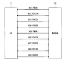
- FIG. 2 is a diagram illustrating physical channels used in an LTE mobile communication system.
- a physical broadcast channel (PBCH) 401 is a channel for downlink transmission from the base station 72 to the mobile terminal 71.
- a BCH transport block (transport block) is mapped to four subframes in a 40 ms interval. There is no obvious signaling of 40ms timing.
- a physical control channel format indicator channel (Physical Control Format Indicator Channel: PCFICH) 402 is a channel for downlink transmission from the base station 72 to the mobile terminal 71.
- PCFICH notifies base station 72 to mobile terminal 71 of the number of OFDM symbols used for PDCCHs (Physical (Downlink Control Channels).
- PCFICH is transmitted for each subframe.
- the physical downlink control channel (Physical Downlink Control Channel: PDCCH) 403 is a channel for downlink transmission from the base station 72 to the mobile terminal 71.
- the PDCCH is one of the transport channels shown in FIG. 3 described later, and is one of the transport channels shown in FIG. 3 and resource allocation information of a downlink shared channel (Downlink Shared Channel: DL-SCH). It reports resource allocation (allocation) information of a certain paging channel (Paging-Channel: PCH) and HARQ (Hybrid-Automatic-Repeat-reQuest) information related to DL-SCH.
- the PDCCH carries an uplink scheduling grant (Uplink Scheduling Grant).
- the PDCCH carries an Ack (Acknowledgement) or Nack (Negative Acknowledgment) (hereinafter also referred to as “Ack / Nack”) which is a response signal (response ⁇ ⁇ signal) to uplink transmission.
- Ack / Nack a response signal (response ⁇ ⁇ signal) to uplink transmission.
- the PDCCH is also called an L1 / L2 control signal.
- a physical downlink shared channel (PDSCH) 404 is a channel for downlink transmission from the base station 72 to the mobile terminal 71.
- PDSCH is mapped with at least one of a downlink shared channel (DL-SCH) and PCH, which are transport channels.
- DL-SCH downlink shared channel
- PCH transport channels
- the physical multicast channel (Physical Multicast Channel: PMCH) 405 is a channel for downlink transmission from the base station 72 to the mobile terminal 71.
- a multicast channel (Multicast Channel: MCH) that is a transport channel is mapped to the PMCH.
- a physical uplink control channel (Physical Uplink Control Channel: PUCCH) 406 is a channel for uplink transmission from the mobile terminal 71 to the base station 72.
- the PUCCH carries Ack / Nack which is a response signal (response signal) for downlink transmission.
- the PUCCH carries a Channel Quality Indicator (CQI) report.
- CQI is quality information indicating the quality of received data or the quality of a communication channel.
- the PUCCH carries a scheduling request (SR).
- a physical uplink shared channel (PUSCH) 407 is a channel for uplink transmission from the mobile terminal 71 to the base station 72.
- UL-SCH Uplink Shared Channel
- the physical HARQ indicator channel (Physical Hybrid ARQ Indicator Channel: PHICH) 408 is a channel for downlink transmission from the base station 72 to the mobile terminal 71.
- PHICH carries Ack / Nack which is a response signal for uplink transmission.
- a physical random access channel (Physical Random Access Channel: PRACH) 409 is a channel for uplink transmission from the mobile terminal 71 to the base station 72.
- the PRACH carries a random access preamble.
- Downlink reference signals are symbols known as mobile communication systems. The following five types of downlink reference signals are defined: Cell-specific reference signals (CRS). MBSFN reference signal (MBSFN reference signal), UE specific reference signal (UE-specific reference signal: demodulation reference signal: DM-RS), positioning reference signal (Positioning reference signal: PRS), channel Information reference signals (Channel-State Information Reference signals: CSI-RS) As a measurement of the physical layer of the mobile terminal, there is a reference signal received power (RSRP) measurement.
- CRS Cell-specific reference signals
- MBSFN reference signal MBSFN reference signal
- UE-specific reference signal UE specific reference signal
- DM-RS demodulation reference signal
- PRS positioning reference signal
- CSI-RS Channel Information Reference signals
- CSI-RS Channel Information Reference signals
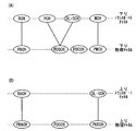
- FIG. 3 is a diagram showing transport channels used in an LTE mobile communication system.
- FIG. 3A shows mapping between a downlink transport channel and a downlink physical channel.
- FIG. 3B shows mapping between the uplink transport channel and the uplink physical channel.
- a broadcast channel (Broadcast Channel: BCH) is broadcast to the entire coverage of the base station (cell).
- BCH is mapped to the physical broadcast channel (PBCH).
- HARQ Hybrid ARQ
- DL-SCH downlink shared channel
- the DL-SCH can be broadcast to the entire coverage of the base station (cell).
- DL-SCH supports dynamic or semi-static resource allocation. Quasi-static resource allocation is also referred to as persistent scheduling.
- DL-SCH supports discontinuous reception (DRX) of a mobile terminal in order to reduce power consumption of the mobile terminal.
- the DL-SCH is mapped to the physical downlink shared channel (PDSCH).
- the Paging Channel supports DRX of the mobile terminal in order to enable low power consumption of the mobile terminal.
- the PCH is required to be broadcast to the entire coverage of the base station (cell).
- the PCH is mapped to a physical resource such as a physical downlink shared channel (PDSCH) that can be dynamically used for traffic.
- PDSCH physical downlink shared channel
- a multicast channel (Multicast Channel: MCH) is used for broadcasting to the entire coverage of a base station (cell).
- the MCH supports SFN combining of MBMS services (MTCH and MCCH) in multi-cell transmission.
- the MCH supports quasi-static resource allocation.
- MCH is mapped to PMCH.
- HARQ Hybrid ARQ
- UL-SCH Uplink Shared Channel
- PUSCH physical uplink shared channel
- Random Access Channel is limited to control information. RACH is at risk of collision.
- the RACH is mapped to a physical random access channel (PRACH).
- PRACH physical random access channel
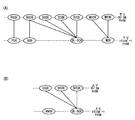
- FIG. 4 is an explanatory diagram for explaining logical channels used in an LTE mobile communication system.
- FIG. 4A shows mapping between the downlink logical channel and the downlink transport channel.
- FIG. 4B shows mapping between the uplink logical channel and the uplink transport channel.
- Broadcast Control Channel is a downlink channel for broadcast system control information.
- the BCCH that is a logical channel is mapped to a broadcast channel (BCH) that is a transport channel or a downlink shared channel (DL-SCH).
- BCH broadcast channel
- DL-SCH downlink shared channel
- the paging control channel (Paging Control Channel: PCCH) is a downlink channel for transmitting changes in paging information (Paging Information) and system information (System Information).
- PCCH is used when the network does not know the cell location of the mobile terminal.
- the PCCH that is a logical channel is mapped to a paging channel (PCH) that is a transport channel.
- PCH paging channel
- the common control channel (Common Control Channel: CCCH) is a channel for transmission control information between the mobile terminal and the base station. CCCH is used when the mobile terminal does not have an RRC (Radio Resource Control) connection with the network.
- RRC Radio Resource Control
- the CCCH is mapped to a downlink shared channel (DL-SCH) that is a transport channel.
- DL-SCH downlink shared channel
- UL-SCH uplink shared channel
- the multicast control channel (Multicast Control Channel: MCCH) is a downlink channel for one-to-many transmission.
- the MCCH is used for transmission of MBMS control information for one or several MTCHs from the network to the mobile terminal.
- MCCH is used only for mobile terminals that are receiving MBMS.
- the MCCH is mapped to a multicast channel (MCH) that is a transport channel.
- the dedicated control channel (Dedicated Control Channel: DCCH) is a channel for transmitting individual control information between the mobile terminal and the network on a one-to-one basis.
- DCCH is used when the mobile terminal is in RRC connection.
- the DCCH is mapped to the uplink shared channel (UL-SCH) in the uplink, and is mapped to the downlink shared channel (DL-SCH) in the downlink.
- the dedicated traffic channel (Dedicated Traffic Channel: DTCH) is a channel for one-to-one communication to individual mobile terminals for transmitting user information.
- DTCH exists for both uplink and downlink.
- the DTCH is mapped to the uplink shared channel (UL-SCH) in the uplink, and is mapped to the downlink shared channel (DL-SCH) in the downlink.
- UL-SCH uplink shared channel
- DL-SCH downlink shared channel
- the multicast traffic channel is a downlink channel for transmitting traffic data from the network to the mobile terminal.
- MTCH is a channel used only for a mobile terminal that is receiving MBMS.
- the MTCH is mapped to a multicast channel (MCH).
- a femtocell base station eg, H (e) NB
- a mobile radio relay station eg, Mobile Relay (e) NB, Mobile ⁇ Relay Node
- H (e) NB represents Home eNB and Home NB
- (E) NB represents eNB and NB.
- Non-Patent Document 5 As a method for estimating the position of such a base station apparatus, there are methods disclosed in the above-mentioned Non-Patent Document 5 and Patent Documents 1 to 3, but even if these methods are used, a movable base station apparatus is available. If it exists, it is difficult to estimate the position of the base station apparatus. In addition, since the position of the base station apparatus is not clear, it is difficult to estimate the position of the mobile terminal apparatus.
- the position of the base station apparatus can be easily estimated, and the position of the mobile terminal apparatus can be easily estimated using the estimation result Is required. Therefore, in the present invention, the configurations of the following embodiments are employed.
- FIG. 5 is a block diagram showing a configuration of the mobile network system 200.
- a mobile network system 200 shown in FIG. 5 has a UE location estimation function disclosed in FIG.
- position estimation may be referred to as “positioning” and UE position estimation may be referred to as “UE positioning”.
- Positioning refers to measuring some position-related signal and estimating the geographical position and moving speed of the position estimation target from the measured information (Non-Patent Document 3, Chapter 4.2 and (See Non-Patent Document 2, Chapter 4.2).
- the mobile network system 200 includes a UE 201, a GERAN (Global System for Mobile Communications (GSM (registered trademark)) and an Enhanced Digital Rate (for GSM Evolution (EDGE) Radio Access Network) 202, a UTRAN (Universal Terrestrial Radio Access Network) 203, E -UTRAN 204, 2G-MSC (Second Generation-Mobile Services-Switching Center) 205, 2G-SGSN (Second Generation-Service-General Packet-Radio Service (GPRS)-Support Node) 206, 3G (Third Generation) SGSN 207, MSC server (server) 208 , MME209, E-SMLC (Evolved, Serving, Mobile, Location, Center) 210, SLP (Secure, User, Plane, Location (SUPL), Location, Platform) 211, GMLC (Gateway, Mobile, Location, Center (MLC)) 212, LRF (Location, Retrieval, Function) 213, P
- devices other than mobile terminal devices such as UE 201 and base station devices (such as eNBs in E-UTRAN 204), such as 2G-MSC205, 2G-SGSN206, 3G-SGSN207, MSC
- the server 208, MME 209, E-SMLC 210, SLP 211, GMLC 212, LRF 213, PPR 214, E-CSCF 215, gsm SCF 216, OSA-LCS 217, external LCS client 218, HSS 219, PMD 220, LIMS-IWF 221 and the like correspond to management devices.
- UE 201 and GERAN 202 are connected by a Um interface 231.
- the UE 201 and the UTRAN 203 are connected by a Uu interface 232.
- UE 201 and E-UTRAN 204 are connected by LTE-Uu interface 233.
- GERAN 202 and 2G-MSC 205 are connected by an A interface 234.
- GERAN 202 and 2G-SGSN 206 are connected by a Gb interface 235.
- GERAN 202 and 3G-SGSN 207 are connected by an Iu interface 236.
- the GERAN 202 and the MSC server 208 are connected by an Iu interface 237.
- the UTRAN 203 and the 3G-SGSN 207 are connected by an Iu interface 238.
- the UTRAN 203 and the MSC server 208 are connected by an Iu interface 239.
- the E-UTRAN 204 and the MME 209 are connected by the S1 interface 240.
- the MME 209 and the E-SMLC 210 are connected by an SLs interface 241.
- the E-SMLC 210 is connected to the SLP 211.
- the GMLC 212 and the 2G-MSC 205 are connected by an Lg interface 242.
- the GMLC 212 and the 2G-SGSN 206 are connected by an Lg interface 243.
- the GMLC 212 and the 3G-SGSN 207 are connected by an Lg interface 244.
- the GMLC 212 and the MSC server 208 are connected by an Lg interface 245.
- the GMLC 212 and the MME 209 are connected by an SLg interface 246.
- GMLC 212 and PPR 214 are connected by an Lpp interface 247.
- the GMLC 212 is connected to the LRF 213.
- the GMLC 212 is connected to the E-CSCF 215 via the LRF 213.
- the LRF 213 is provided separately from the GMLC 212, but may include the GMLC 212.
- the LRF 213 and the E-CSCF 215 are connected by the MI interface 248.
- the GMLC 212 and the gsmSCF 216 are connected by an Lc interface 249.
- the GMLC 212 and the OSA-LCS 217 are connected by a dedicated interface 250.
- the GMLC 212 and the external LCS client 218 are connected by a Le interface 251.
- the gsmSCF 216 and the OSA-LCS 217 can be connected by a dedicated interface 252.
- the OSA-LCS 217 and the external LCS client 218 can be connected by the OSA API 253.
- the GMLC 212 and the HSS 219 are connected by an Lh / SLh interface 254.
- the GMLC 212 and PMD 220 are connected by a Lid interface 255.
- the GMLC 212 and the LIMS-IWF 221 are connected by a Le interface 256.
- the GERAN 202 is a GSM (Global System for Mobile Communications) radio access network, which is a second generation (2G) radio communication system.
- the UTRAN 203 is a UMTS (Universal Mobile Telecommunications System) radio access network that is a third generation (3G) radio communication system.
- the E-UTRAN 204 is an evolved UMTS (Evolved UMTS) radio access network that is a 3.9th generation (3.9G) radio communication system.
- the 2G-MSC 205 and the MSC server 208 perform control and management of circuit-switched calls, authentication processing of the UE 201, and management of requests related to location estimation of the UE 201.
- 2G-SGSN 206 and 3G-SGSN 207 perform control and management of packet-switched calls, authentication processing of UE 201, and management of requests related to UE 201 location estimation.
- the MME 209 performs call control and management in the E-UTRAN 204, authentication processing of the UE 201, and management of requests related to the location estimation of the UE 201.
- the E-SMLC 210 performs position estimation control and calculation of the UE 201 located in the E-UTRAN 204.
- SLP211 is an entity that performs management and location determination of SUPL (Secure User Plane Location) service defined by OMA (Open Mobile Alliance) (see OMA-AD-SUPL v2.0).
- SUPL Secure User Plane Location
- OMA Open Mobile Alliance
- the GMLC 212 has a main function regarding a location service (Location Service), and functions as an interface with a plurality of radio access networks of the same PLMN and an interface with another PLMN.
- Location Service Location Service
- the LRF 213 is an entity having a function of detecting location information of the UE 201 where an emergency communication session such as an emergency call in an IMS (IP Multimedia Subsystem) architecture is established.
- IMS IP Multimedia Subsystem
- the PPR 214 is an entity that maintains and manages a profile (information) related to subscriber privacy.
- the E-CSCF 215 is an entity that controls an emergency communication session such as an emergency call in the IMS architecture.
- GsmSCF 216 is a GSM system control function that performs access by CAMEL (Customized Applications for Mobile Enhanced Logic) for LCS.
- OSA-LCS 217 is an OSA for using a network function for location information service.
- the OSA-LCS 217 is a function group that provides an open API (Application Programming Interface) (see, for example, 3GPP TS 22.127, TS 23.198, TS 29.198).
- open API Application Programming Interface
- External LCS client 218 is a client that can request measurement of the location of UE 201 outside mobile network system 200.
- the HSS 219 is a subscriber information management entity that manages subscriber information.
- the PMD 220 uses a pen name (Pseudonym) for communication related to location information services, such as a pen name, MSISDN (Mobile Subscriber Integrated Services Digital Network Number), and IMSI (International Mobile Subscriber Identity).
- Pseudonym for communication related to location information services, such as a pen name, MSISDN (Mobile Subscriber Integrated Services Digital Network Number), and IMSI (International Mobile Subscriber Identity).
- MSISDN Mobile Subscriber Integrated Services Digital Network Number
- IMSI International Mobile Subscriber Identity
- the LIMS-IWF 221 is a system based on the IMS (IP Multimedia Subsystem) architecture in the location service, and has a function for interconnection with other networks.
- the LIMS-IWF 221 has a function of exchanging a public user identity (Public User Identity) of an IMS of a subscriber.
- Public User Identity Public User Identity
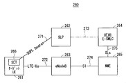
- FIG. 6 is a block diagram showing a configuration of a conventional wireless communication system 260 in E-UTRAN.
- a conventional wireless communication system 260 in E-UTRAN shown in FIG. 6 is disclosed in FIG.
- the radio communication system 260 includes a target UE 261, an SLP 262, an eNodeB 263, a UE E-SMLC 264, and an MME 265.
- the target UE 261 includes a SET (SUPL Enabled Terminal) 266.
- the target UE 261 and the eNodeB 263 are connected by the LTE-Uu interface 272.
- the eNodeB 263 and the MME 265 are connected by the S1 interface 274.
- the E-SMLC 264 for UE and the MME 265 are connected by an SLs interface 275.
- a logical connection is established between the SET 266 and the SLP 262 in the target UE 261. This is called a SUPL (Secure User Plane Location) bearer 271.
- the SLP 262 and the UE E-SMLC 264 can be connected by a dedicated interface 273.
- ENodeB (E-UTRAN NodeB) 263 is a base station apparatus that terminates a wireless communication protocol in E-UTRAN.
- SUPL Secure User Plane Location
- SLP262 SLP262
- SET266 are entities having functions in SUPL defined by OMA (Open Mobile Alliance) (see OMA-AD-SUPL v2.0).
- the SUPL bearer 271 is a user bearer in SUPL.
- the SLP 262 is an entity that manages and locates the SUPL service.
- SET 266 is a terminal function having a SUPL communication function.
- the target UE 261, MME 265 and UE E-SMLC 264 have the same configurations as the UE 201, MME 209 and E-SMLC 210 in the mobile network system 200 shown in FIG.
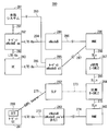
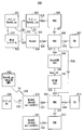
- FIG. 7 is a block diagram showing a configuration of the wireless communication system 280 in the first embodiment of the present invention.
- the wireless communication system 280 includes a target UE 261, SLP 262, eNodeB 263, UE E-SMLC 264 and MME (hereinafter also referred to as “first MME”) 265 similar to the wireless communication system 260 shown in FIG. Vehicular TM System) 281, target eNodeB_uu 282, UE 283, eNodeB 284, target eNodeB_s1 285, second MME 286, and E-SMLC 287 for eNB.
- first MME MME
- the vehicle system 281 and the target eNodeB_Uu 282 are connected by a V interface 291.
- the vehicle system 281 and the target eNodeB_s1 285 are connected by a V interface 293.
- the target eNodeB_Uu 282 and the UE 283 are connected by the LTE-Uu interface 292.
- the target eNodeB_Uu 282 and the eNodeB 284 are connected by the LTE-Uu interface 294.
- the target eNodeB_Uu 282 and the eNodeB 284 may be connected by an LTE-Un interface.
- the UE 283 and the target eNodeB_s1 285 are connected by the LTE-Uu interface 295.
- the eNodeB 284 and the second MME 286 are connected by the S1 interface 296.
- the target eNodeB_s1 285 and the second MME 286 are connected by the S1 interface 297.
- the second MME 286 and the E-SMLC 287 for eNB are connected by an SLs interface 298.
- the E-SMLC 287 for eNB and the E-SMLC 264 for UE are connected by an SLLs interface 299.
- an E-SMLC 287 for eNB is newly provided in addition to the E-SMLC 264 for UE used for UE position estimation in the conventional radio communication system 260 shown in FIG.
- the vehicle system 281 estimates the position and speed of the moving structure. The information about can be measured and estimated.
- the e-SMLC 287 for eNB is an entity that manages and calculates the location information of the eNodeB in E-UTRAN.
- the target eNodeB_uu 282 is a movable eNodeB.
- the target eNodeB_uu 282 is an eNodeB that is wirelessly connected to the network side by a wireless connection interface such as an LTE-Uu interface or an LTE-Un interface.
- the target eNodeB_uu 282 is, for example, a mobile relay device (Mobile Relay Node).
- Target eNodeB_s1 285 is an eNodeB that is wired to the network side by a wired connection interface such as an S1 interface.
- the target eNodeB_s1 285 is, for example, a femtocell base station (HeNB).
- FIG. 7 is a diagram showing a logical configuration, not a physical configuration.
- the E-SMLC 287 for eNB and the E-SMLC 264 for UE are described independently, but this description shows that the E-SMLC 287 for eNB and the E-SMLC 264 for UE are physically independent. It does not indicate that it is a device.
- the e-SMLC 287 for eNB and the E-SMLC 264 for UE may be configured as separate devices or may be configured as one device.
- Table 1 shows the functions related to position estimation of each logical block shown in FIG.
- a logical block in which each function is arranged is indicated by a symbol “ ⁇ ”.
- a position estimation function (Positioning function (positioning function)) 301 includes a PRCF for UE, a PCF for UE, a PSMF for UE, a PRRM for UE, a PRCF for eNB, a PCF for eNB, a PSMF for eNB, and a PRRM for eNB.
- a position estimation function (Positioning function)) 301 includes a PRCF for UE, a PCF for UE, a PSMF for UE, a PRRM for UE, a PRCF for eNB, a PCF for eNB, a PSMF for eNB, and a PRRM for eNB.
- the PRCF for UE, the PCF for UE, the PSMF for UE, and the PRRM for UE are PRCF (Positioning Radio Co-ordination Function), PCF (described in Chapters 5 and 6 of Non-Patent Document 1). It corresponds to Positioning PositionCalculation Function), PSMF (Positioning Signal Measurement Function) and PRRM (Positioning Radio Resource Management).
- the PRCF for eNB the PCF for eNB, the PSMF for eNB, and the PRRM for eNB are intended for position estimation of the eNB, and the contents thereof are Chapters 5 and 6 of Non-Patent Document 1. It is the same as each function described in.
- the location client functions (location client functions: LCF) 302 include an LCF for UE and an LCF for eNB.
- System handling functions (System handling functions) 303 are LSCF for UE, LSBF for UE, LSOF for UE, LSBcF for UE, LSCTF for UE, LIMS-IWF for UE, LCF for eNB, LSCF for eNB, LSBF for eNB, eNB LSOF for LNB, LSBcF for eNB, LSCTF for eNB, and LIMS-IWF for eNB.
- the LCF for UE in the location client function 302, and the LSCF for UE, the LSBF for UE, the LSOF for UE, the LSBcF for UE, the LSCTF for UE, and the LIMS-IWF for UE in the system handling function 303 are the position estimation function 301. Similar to the functions of LCF (Location Client Function), LSCF (Location System Function Function), LSBF (Location System Function Function), and LSOF (Location System Operation Functions) described in Chapters 5 and 6 of Non-Patent Document 1. ), LSBcF (Location System Broadcast Function), LSCTF (Location System Co-ordinate Transformation Function) and LIMS-IWF (Location IMS Interworking Function).
- eNB LCF eNB LCF
- eNB LSCF eNB LSBF
- eNB LSOF eNB LSBcF
- eNB LSCTF eNB LIMS-IWF
- eNB LIMS-IWF eNB position estimation, similar to the position estimation function 301.
- the contents are the same as the functions described in Chapters 5 and 6 of Non-Patent Document 1.
- the PCF for eNB that is the PCF for the eNB in the position estimation function 301 is arranged in the vehicle system, UE, eNB_uu / s1, and E-SMLC for eNB.
- the PSMF for eNB that is the PSMF for the eNB in the position estimation function 301 is arranged in the vehicle system, the UE, the eNB_uu / s1, and the eNB.
- the PRRM for eNB that is a PRRM for the eNB in the position estimation function 301 is arranged in the eNB.
- the PRCF for eNB which is the PRCF for the eNB in the position estimation function 301, is arranged in the E-SMLC for eNB.
- the eNB PSMF arranged in the eNB_uu / s1 is for GNSS signals (hereinafter sometimes referred to as “GNSS signals”) and other eNB signals, and as positioning methods (Positioning method), E_PM_1, E_PM_2, E_PM_3 , E_PM_4 or E_PM_5 is used.
- GNSS signals GNSS signals
- E_PM_1, E_PM_2, E_PM_3 , E_PM_4 or E_PM_5 is used.
- the PCF for eNB and PSMF for eNB arranged in the UE have the same functions as the UE position estimation, and are applied when E_PM_4 is used as the positioning method.
- the PCF for eNB and PSMF for eNB arranged in the vehicle system relate to position information measured or estimated in moving structures such as a train operation system and a car navigation system, and when E_PM_6 is used as a positioning method Applied.
- the PSMF for eNB arranged in the eNB is applied when E_PM_1, E_PM_2, E_PM_3, or E_PM_5 is used as a positioning method.
- the positioning method will be described later.
- the LCF for eNB which is the location client function 302 for the eNB, is assumed to be arranged in eNB_uu / s1, MME, and E-SMLC for eNB.
- the LCF for eNB arranged in eNB_uu / s1 resets the position measurement when the eNB is reset and the installation position can be changed, but the eNB operated basically in a fixed state detects movement. And implemented to request again.
- the LCF for eNB arranged in the E-SMLC for eNB is mounted to execute a position estimation request when additional measurement is required based on the position estimation result.
- the E-SMLC for eNB is used. to add. This is implemented for the purpose of activating UE location estimation in order to improve eNB location estimation accuracy.
- Table 2 shows six positioning methods.
- the mobile relay node Mobile ⁇ Relay Node; Mobile RN: mobile RN
- Mobile RN mobile RN
- E_PM_1 shown in Table 2 is a network support GNSS method.
- E_PM_2 is a downlink positioning method.
- E_PM_3 is an extended cell ID method.
- E_PM_4 is a method based on UE tracking information.
- E_PM_5 is a method based on mobile eNB tracking information.
- E_PM_6 is a method based on auxiliary vehicle information.
- E_PM_1, E_PM_2, and E_PM_3 are functions similar to the UE position estimation described in Non-Patent Document 2.
- E_PM_1, E_PM_2, and E_PM_3 receive and measure a GNSS signal for eNB_uu / s1 that is a target of position estimation, perform calculation on the result, and receive and measure downlink signals of other eNBs.
- a function for performing calculation on the result is mounted, and position estimation is performed in the same manner as the operation of the UE.
- E_PM_4 uses eNB_uu / s1 information related to eNB_uu / s1, such as current and past location estimation histories of UEs located in the cell of eNB_uu / s1 to be subjected to location estimation, serving cell information, and measurement information. The position is estimated. E_PM_4 is effective when GNSS radio waves and other eNB radio waves cannot be received. Further, E_PM_4 is effective for "eNB that can change the installation position but basically operates in a fixed state".
- E_PM_5 uses information related to eNB_uu / s1 such as position estimation results of E_PM_1, E_PM_2, and E_PM_3 for eNB_uu / s1 that are subject to position estimation, or position estimation history and measurement information for current and past eNB_uu / s1, Position estimation is performed.
- the information on eNB_uu / s1 may include in-zone cell information when the position estimation target is eNB_uu.
- E_PM_5 is mainly effective for “eNB that is basically operated while moving”.
- E_PM_6 is applied to the eNB installed in the moving structure.
- E_PM_6 performs position estimation using position information measured and estimated in a moving structure such as a train operation system and a car navigation system, and speed information.
- position management is performed in the moving state and position estimation is performed using information on a plurality of UEs. Assume that there are three estimation requests of (3) to (3).
- Position estimation request (location service request) for estimating the current position using measurement information at one time
- Position estimation request for estimating one position using a plurality of pieces of information in time
- Location estimation request (second location update process request) for continuously performing the measurement of (1) assuming operation during movement
- “location service request” is referred to as “LS request”
- first location update process request is referred to as “first LUP request”
- second location update process request is referred to as “second LUP request”.
- the first LUP request is intended for “eNB that can change the installation position but basically operates in a fixed state”, and the second LUP request is “operated while moving basically”. eNB ".
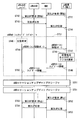
- FIG. 8 is a diagram illustrating an example of an LS request sequence. In this sequence, it is possible to apply all the above-mentioned eNB positioning methods (eNB Positioning Method).
- eNodeB_uu / s1 When a position estimation request is generated in eNodeB_uu / s1 serving as an LCF, in step ST1, eNodeB_uu / s1 transmits an LS request to the MME.
- eNodeB_uu / s1 transmits an LS request to the MME in step ST2.
- step ST3 the MME recognizes an LS request as an internal event to be performed.
- the MME that has received the LS request or recognized as an internal event notifies the E-SMLC for eNB of the LS request in step ST4.
- the processes in steps ST1 to ST3 described above are independent, and when any one process selected from these steps is performed, the MME performs a process in step ST4.
- step ST5 the E-SMLC for eNB, the eNodeB, and the MME perform an eNodeB procedure. Specifically, the E-SMLC for eNB that has received the LS request from the MME exchanges measurement data and auxiliary data related to position estimation between the eNodeB and the MME that are the targets of position estimation as necessary. .
- Step ST6 the eNodeB_uu / s1, the eNodeB, the MME, and the E-SMLC for eNB perform the eNodeB_uu / s1 procedure.
- data necessary for position estimation is exchanged as eNodeB_uu / s1 procedure among the eNodeB_uu / s1, the eNodeB, the MME, and the e-SMLC for eNB that are the targets of position estimation.
- step ST7 the E-SMLC for eNB performs position estimation.
- the E-SMLC for eNB that has completed the position estimation records the estimation result and the reliability calculated based on the estimation result in the eNodeB management table (hereinafter also referred to as “location table”), and updates the location table. To do.
- Step ST8 the E-SMLC for eNB adds the estimated location information and transmits an LS response indicating the completion of processing to the MME.
- the MME that has received the LS response from the E-SMLC for eNB transmits the LS response to the request source.
- the MME transmits an LS response to eNodeB_uu / s1 in step ST9.
- the MME transmits an LS response to the E-SMLC for eNB in step ST10.
- the MME When the MME itself is the request source, that is, when the process of the above-described step ST3 is performed, the MME confirms the LS response by itself in step ST11.
- the accuracy may be improved by performing position estimation again with another positioning method or procedure.
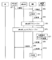
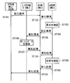
- FIG. 9 is a diagram illustrating an example of a sequence when a method based on UE tracking information of E_PM_4 is used as the positioning method and the first LUP request is used.
- step ST21 the E-SMLC for eNB transmits a first location update process (LUP) request message to the MME to notify the start of processing.
- LUP first location update process
- the first LUP request message can notify the start (start), stop (stop) and positioning method.
- the MME that has received the first LUP request message indicating the start of the process transmits the request message, that is, the first LUP request message indicating the start of the process, to the eNodeB_uu / s1 in step ST22 to notify the start of the process. To do.
- the eNodeB_uu / s1 that has received the first LUP request message indicating the start of processing confirms that the positioning method is E_PM_4 in step ST23, and notifies the UE by using system information or the like, or by the dedicated channel to the UE.
- the own cell is notified that it is a cell located by a method based on UE tracking information of E_PM_4 (hereinafter referred to as a “cell of a method based on UE tracking information”).
- a specific field may be set as system information, or a field such as CSG (Closed Subscriber Group) may be substituted. When the CSG field is used, information from the UE is always accepted in all CSG cells.
- step ST24 the eNodeB_uu / s1 transmits a first LUP response message to the MME.
- the MME that has received the first LUP response message transmits the first LUP response message to the E-SMLC for eNB in step ST25. As a result, the first LUP is activated.
- the eNB location update procedure in step ST31 performed between the UE, eNodeB_uu / s1, eNodeB, MME, and E-SMLC for eNB can be activated at an arbitrary timing.
- the eNB location update procedure in step ST31 includes the processes in steps ST26 to ST30 described below.
- the UE located in this cell first receives system information and recognizes that this cell is a cell of a method based on UE tracking information.
- the UE that has recognized that it is a cell of the method based on the UE tracking information performs measurement of information on the position estimation of the current position as necessary, and immediately, in Step ST26, by the UE location information report, Information about the position estimation measured at present and in the past is transmitted to the MME.
- step ST26 by transmitting the UE location information report in step ST26, the eNB location update configured by the processes of step ST26 to step ST30 performed among the UE, eNodeB_uu / s1, eNodeB, MME, and E-SMLC for eNB The procedure is started.
- TAU Tracking Area Update
- this process can be applied not only to the UE in the RRC_Idle state but also to the UE in the RRC_Connected state by transmitting the UE location information report through a dedicated channel or the like.
- the accuracy of position estimation can be improved. It is also possible not to transmit information related to position estimation by setting the UE and network equipment.
- the RRC_Idle state is a standby state
- the RRC_Connected state is an RRC connection state.
- PLMN Public Land Mobile Mobile Network
- SI System Information
- the mobile terminal has an RRC connection (connection), can transmit / receive data to / from the network, and performs handover (Handover: HO), measurement of a neighbor cell (Neighbour cell), and the like.
- Step ST27 the MME that has received the UE location information report transmits the received information to the E-SMLC for eNB as a UE location information report between the MME and the E-SMLC for eNB.
- step ST28 the E-SMLC for eNB that has received the UE location information report performs position estimation using the UE location information included in the UE location information report, the UE information received in the past, the position estimation result, and the like. .
- the E-SMLC for eNB that has completed the position estimation records the estimation result and the reliability calculated based on the estimation result in the location table that is an eNodeB management table, and updates the location table.
- Step ST29 the E-SMLC for eNB transmits the updated position information and information related thereto to the MME as eNB location update information.
- the MME that has received the eNB location update information transmits the received information to the eNB_uu / s1 as eNB location update information between the MME and the eNB_uu / s1 in Step ST30.
- step ST31 the process of the eNB location update procedure in step ST31 is repeatedly performed.
- step ST32 If a stop request is generated due to factors such as sufficient accuracy being obtained in the E-SMLC for eNB, the process proceeds to step ST32.
- step ST32 the E-SMLC for eNB transmits a first LUP request message indicating processing stop to the MME, and notifies the processing stop.
- Step ST33 the MME that has received the first LUP request message indicating the process stop transmits a first LUP request message indicating the process stop to the eNodeB_uu / s1 to notify the process stop.
- Step ST34 the eNodeB_uu / s1 that has received the first LUP request indicating the processing stop is notified using system information or the like, or the UE is not a cell of the method based on the UE tracking information by the dedicated channel. Notice.
- step ST35 the eNodeB_uu / s1 transmits a first LUP response message to the MME.
- Step ST36 the MME that has received the first LUP response message transmits the first LUP response to the E-SMLC for eNB.
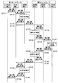
- FIG. 10 is a diagram illustrating an example of a sequence when the method based on the mobile eNB tracking information of E_PM_5 is used as the positioning method and the second LUP request is used.
- step ST41 the E-SMLC for eNB transmits a second LUP request message indicating the start of processing to the MME, and notifies the start of processing.
- the second LUP request message can notify the start (start), stop (stop) and positioning method.
- step ST42 the MME that has received the second LUP request message indicating the start of processing transmits the message, that is, the second LUP request message indicating the start of processing, to eNodeB_uu / s1 that is the target of position estimation, and notifies the start of processing. To do.
- the eNodeB_uu / s1 that has received the second LUP request message indicating the start of processing confirms that the positioning method is E_PM_5, and transmits a second LUP response message to the MME in step ST43.
- the MME that has received the second LUP response message transmits the received information to the E-SMLC for eNB as a second LUP response message between the MME and the E-SMLC for eNB in step ST44. As a result, the second LUP is activated.
- the eNB location update procedure in step ST51 performed between eNodeB_uu / s1, eNodeB, MME, and E-SMLC for eNB can be activated at an arbitrary timing.
- the eNB location update procedure in step ST51 includes the processes in steps ST45 to ST50 described below.
- step ST45 the eNodeB_uu / s1 starts measurement and calculation of information related to periodic or irregular position estimation.
- Step ST46 the eNodeB_uu / s1 transmits information on the position estimation to the MME periodically or irregularly by the eNB location information report.
- the information regarding the position estimation that is measured and calculated by the eNodeB_uu / s1 and transmitted to the MME relates to, for example, E_PM_1, E_PM_2, and E_PM_3 shown in Table 2.
- the MME that has received the eNB location information report transmits the received information to the E-SMLC for eNB as an eNB location information report between the MME and the E-SMLC for eNB in step ST47.
- the E-SMLC for eNB that has received the eNB location information report uses the eNB location information, the route map of the moving structure, the eNB installation position information, and the like included in the eNB location information report. I do.
- the E-SMLC for eNB that has completed the position estimation records the estimation result and the reliability calculated based on the estimation result in the location table that is an eNodeB management table, and updates the location table.
- step ST49 the E-SMLC for eNB transmits the updated position information and information related thereto to the MME as eNB location update information.
- MME which received eNB location update information transmits received information to eNB_uu / s1 as eNB location update information between MME and eNB_uu / s1 in step ST50.
- step ST51 The process of the eNB location update procedure in step ST51 is repeatedly performed.
- step ST52 If a stop request is generated due to factors such as sufficient accuracy being obtained in the E-SMLC for eNB, the process proceeds to step ST52.
- Step ST52 the E-SMLC for eNB notifies the MME of a second LUP request message indicating processing stop.
- Step ST53 the MME that has received the second LUP request message indicating the process stop transmits a second LUP request message indicating the process stop to the eNodeB_uu / s1 to notify the process stop.
- Step ST54 the MME that has received the second LUP response message transmits the second LUP response message to the E-SMLC for eNB.
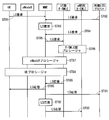
- FIG. 11 is a diagram illustrating an example of a sequence when a method based on auxiliary vehicle information of E_PM_6 is used as a positioning method and a second LUP request is used.
- E-SMLC for eNB which is an LCF
- the eNB to be estimated is installed in a moving structure such as a train, and information related to position estimation can be obtained from the vehicle system (Vehicular System) of the moving structure
- vehicle system Vehicle System
- Step ST61 the E-SMLC for eNB transmits a second LUP request message indicating the start of processing to the MME and notifies the start of processing.
- Step ST62 the MME that has received the second LUP request message indicating the start of processing notifies the eNodeB_uu / s1 of the position estimation target of the second LUP request message indicating the start of processing.
- the eNodeB_uu / s1 that has received the second LUP request message indicating the start of processing confirms that the positioning method is E_PM_6, and transmits a second LUP response message to the MME in step ST63.
- Step ST64 the MME that has received the second LUP response message transmits the received information to the E-SMLC for eNB as a second LUP response message between the MME and the E-SMLC for eNB. As a result, the second LUP is activated.
- the eNB location update procedure in step ST71 performed between the vehicle system, eNodeB_uu / s1, eNodeB, MME, and E-SMLC for eNB can be activated at any timing.
- the eNB location update procedure in step ST71 includes the processes in steps ST65 to ST70 described below.
- step ST65 the vehicle system transmits information on position estimation to the eNodeB_uu / s1 regularly or irregularly as a vehicle location information report.
- the eNodeB_uu / s1 that has received the vehicle location information report performs a calculation regarding information related to position estimation from the vehicle system that is received regularly or irregularly.
- step ST66 eNodeB_uu / s1 transmits the information regarding the position estimation to MME regularly or irregularly by an eNB location information report.
- Step ST67 the MME that has received the eNB location information report transmits the received information to the E-SMLC for eNB as an eNB location information report between the MME and the E-SMLC for eNB. That is, the MME transfers the received eNB location information to the E-SMLC for eNB.
- the E-SMLC for eNB that has received the eNB location information report uses the eNB location information, the route map of the moving structure, the eNB installation position information, and the like included in the eNB location information report. I do.
- the e-SMLC for eNB that has completed the position estimation records the estimation result, the reliability calculated based on the estimation result, and the location table in the eNodeB management table, and updates the location table.
- Step ST69 the E-SMLC for eNB transmits eNB location update information to the MME.
- the MME that has received the eNB location update information transmits the received information to the eNB_uu / s1 as eNB location update information between the MME and the eNB_uu / s1 in Step ST70.
- step ST71 The process of the eNB location update procedure in step ST71 is repeatedly performed.
- the process proceeds to step ST72.
- Step ST72 the E-SMLC for eNB transmits a second LUP request message indicating processing stop to the MME, and notifies the processing stop.
- Step ST73 the MME that has received the second LUP request message indicating the process stop transmits a second LUP request message indicating the process stop to the eNodeB_uu / s1 to notify the process stop.
- Step ST74 the MME that has received the second LUP response message transmits the received information to the ENB for eNB as a second LUP response message between the MME and the E-SMLC for eNB.
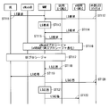
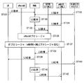
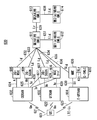
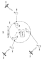
- FIG. 12 is a diagram illustrating an example of a sequence when performing UE location estimation using a movable eNB location estimation result.
- FIG. 12 is a diagram illustrating an example of a sequence in which a procedure using a position estimation result of a movable eNB is added to the sequence disclosed in FIG. 5.1-1 of Non-Patent Document 7 (3GPP TS26.305).
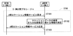
- FIG. 13 is a diagram showing an exemplary sequence of the procedure between E-SMLC in step ST86 shown in FIG.
- Step ST81 the UE transmits an LS request to the MME.
- step ST82 the external LCS client transmits an LS request to the MME.
- step ST83 the MME recognizes an LS request as an internal event to be performed.
- Step ST84 the E-SMLC for eNB transmits an LS request to the MME.
- the MME that has received the LS request or has recognized it as an internal event notifies the UE E-SMLC of the LS request in step ST85.
- the processes in steps ST81 to ST84 described above are independent, and when any one process selected from these steps is performed, the MME performs the process in step ST85.
- the E-SMLC for UE that has received the LS request message determines whether or not the NB request of the mobile eNB is based on information such as whether or not the mobile cell or the neighboring cell includes a mobile eNB in the location estimation target LS request. It is determined whether the “position estimation result” is necessary. If it is determined that the “position estimation result of movable eNB” is necessary, the E-SMLC for UE and the E-SMLC for eNB perform an inter-E-SMLC procedure (InterSME-SMLC Procedures) in Step ST86. . Specifically, the E-SMLC for UE makes an inquiry about the location information of the target eNB to the E-SMLC for eNB.
- step ST101 shown in FIG. 13 the E-SMLC for UE transmits an eNB location information service request to the E-SMLC for eNB.
- Step ST102 the E-SMLC for eNB searches for location data or measures information related to position estimation of the target eNB.
- Step ST103 the E-SMLC for eNB transmits an eNB location information service response to the E-SMLC for UE.
- step ST87 the eNodeB, the MME, and the E-SMLC for UE perform the eNodeB procedure.
- the eNodeB procedure measurement data and auxiliary data related to position estimation are exchanged between the eNodeB, the MME, and the E-SMLC for UE as necessary.
- step ST88 the UE, eNodeB, MME and UE E-SMLC perform the UE procedure.
- the UE procedure data necessary for position estimation is exchanged with the target UE among the UE, the eNodeB, the MME, and the E-SMLC for UE. Then, position estimation is performed by E-SMLC for UE.
- step ST89 the E-SMLC for UE that has completed the position estimation adds the estimated position information and the reliability calculated based on the estimated result and the estimated result to the LS response to the MME. Send.
- the MME that has received the LS response transmits the LS response to the request source. Specifically, when the UE is a request source, that is, when the process of step ST81 described above is performed, the MME transmits an LS response to the UE in step ST90.
- the MME transmits an LS response to the external LCS client in step ST91.
- Step ST83 the MME confirms the LS response by itself in Step ST92.
- the MME transmits an LS response to the E-SMLC for eNB in step ST93.
- FIG. 14 and FIG. 15 are diagrams showing an example of a sequence when the execution timing of the procedure between E-SMLC is different from FIG.
- FIG. 14 shows a sequence in the case of performing together with the eNodeB procedure
- FIG. 15 shows a sequence in the case of performing together with the UE procedure. This is a sequence for the case where “location estimation result of movable eNB” is necessary in each procedure.
- steps ST81 to ST85 and steps ST88 to ST93 in FIG. 12 are the same as steps ST81 to ST85 and steps ST88 to ST93 in FIG. 12, and thus a common description is omitted.
- step ST116 the eNodeB, the MME, the E-SMLC for UE, and the E-SMLC for eNB perform an eNodeB procedure.
- step ST131 to step ST135, step ST136 and step ST138 to step ST142 shown in FIG. 15 is the same as each process of step ST81 to step ST85, step ST87 and step ST89 to step ST93 shown in FIG. The common explanation is omitted.
- step ST137 the UE, eNodeB, MME, E-SMLC for UE, and E-SMLC for eNB perform UE procedures.
- FIG. 16 is a block diagram showing a configuration of the UE in the first embodiment of the present invention.
- the UE 310 includes a wireless communication control unit 311, a position calculation unit 312, a wireless communication signal transmission / reception unit 313, a wireless communication signal measurement unit 314, a GNSS signal reception / measurement unit 315, and an application function unit 316.
- the wireless communication control unit 311 performs communication protocol control and device management for wireless communication.
- the wireless communication control unit 311 has a PRRM function.
- the position calculation unit 312 has a PCF and performs calculations related to position estimation of the UE and the eNB.
- the wireless communication signal transmission / reception unit 313 performs modulation and demodulation, channel coding, frequency conversion, and the like for transmitting and receiving wireless communication signals.
- the wireless communication signal measurement unit 314 has PSMF for a wireless communication signal.
- the GNSS signal reception / measurement unit 315 has PSMF for the GNSS signal.
- the application function unit 316 performs user interface and application processing.
- FIG. 17 is a block diagram showing a configuration of eNB_uu / s1 320 in the first embodiment of the present invention.
- eNB_uu / s1 320 includes a radio communication control unit 321, a position calculation unit 322, a radio communication signal transmission / reception unit 323, a radio communication signal measurement unit 324, a GNSS signal reception / measurement unit 325, a vehicle system IF unit 326, and a network IF unit 327. It is prepared for.
- the wireless communication control unit 321 performs communication protocol control and device management for wireless communication.
- the wireless communication control unit 321 has a PRRM function.
- the position calculation unit 322 has a PCF and performs calculations related to position estimation of the UE and the eNB.
- the wireless communication signal transmission / reception unit 323 performs modulation and demodulation, channel coding, frequency conversion, and the like for transmitting and receiving wireless communication signals.
- the wireless communication signal measurement unit 324 has PSMF for a wireless communication signal.
- the GNSS signal reception / measurement unit 325 has a PSMF for the GNSS signal.
- the vehicle system IF unit 326 has an interface function for communicating with the vehicle system.
- the network IF unit 327 has an interface function for communicating with the vehicle system IF unit 326, the MME, and the like.
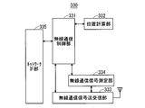
- FIG. 18 is a block diagram illustrating a configuration of the eNB 330 according to the first embodiment of this invention.
- the eNB 330 includes a wireless communication control unit 331, a position calculation unit 332, a wireless communication signal transmission / reception unit 333, a wireless communication signal measurement unit 334, and a network IF unit 335.
- the wireless communication control unit 331 performs communication protocol control and device management for wireless communication.
- the wireless communication control unit 331 has a PRRM function.
- the position calculation unit 332 has a PCF and performs calculations related to position estimation of the UE and the eNB.
- the wireless communication signal transmission / reception unit 333 performs modulation and demodulation, channel coding, frequency conversion, and the like for transmitting and receiving wireless communication signals.
- the wireless communication signal measurement unit 334 has PSMF for a wireless communication signal.
- the network IF unit 335 has an interface function for communicating with an MME or the like.
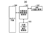
- FIG. 19 is a block diagram showing a configuration of the E-SMLC 340 for eNB according to the first embodiment of the present invention.
- the e-SMLC 340 for eNB includes a position estimation radio communication control unit 341, an eNB position calculation unit 342, an E-SMLC communication control unit 343 for UE, and a network IF unit 344.
- the location estimation radio communication control unit 341 has a radio communication protocol control function (PRCF) and a device management function for eNB location estimation.
- the eNB position calculation unit 342 has a PCF related to the eNB.
- the UE E-SMLC communication control unit 343 performs communication control with the UE E-SMLC.
- the network IF unit 344 has an interface function for communicating with an MME or the like.
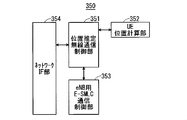
- FIG. 20 is a block diagram showing a configuration of the E-SMLC 350 for UE in the first embodiment of the present invention.
- the UE E-SMLC 350 includes a location estimation radio communication control unit 351, a UE location calculation unit 352, an eNB E-SMLC communication control unit 353, and a network IF unit 354.
- the location estimation radio communication control unit 351 has a radio communication protocol control function (PRCF) and a device management function for UE location estimation.
- the UE location calculation unit 352 has a PCF related to the UE.
- the eNB E-SMLC communication control unit 353 performs communication control with the eNB E-SMLC.
- the network IF unit 354 has an interface function for communicating with an MME or the like.
- the e-SMLC for eNB which is a management apparatus, performs measurement and calculation for estimating base station position information, which is information related to the position of the base station, and estimates base station position information. Functions as position estimation processing means. Based on the base station position information related to the position of the base station estimated by the eNB SM for eNB, various processes are performed by the management apparatus including the eNB SM for eNB.
- the processing by the management apparatus includes radio communication control in communication between a mobile terminal (UE) and a base station, communication call control, movement management of the mobile terminal, management of the radio communication system, and position information of apparatuses constituting the radio communication system. It is at least one process of management.
- wireless communications system contains a mobile terminal and a base station apparatus.
- the function of the position estimation processing means for estimating the base station position information is mounted in the wireless communication system by performing measurement and calculation for estimating the base station position information.
- the processing means for position estimation obtains “various measurement information for position estimation or information obtained by processing the measurement information” by the above-described measurement and calculation, and uses this as “base position position information”. Information indicating an estimated position as a result of estimation is estimated.
- the information related to the position estimation of the base station includes both “various measurement information for position estimation or information obtained by processing the measurement information” and “information indicating the estimated position as a result of position estimation”.
- the information on the position estimation of the base station includes the measurement information of the wireless network by the base station itself, the measurement history information and cell history information of the mobile terminal, the peripheral cell measurement history information of the base station itself, and the mobile structure in which the base station is mounted
- information on the current position estimation of the object for example, information on current position estimation in a car navigation system, train operation information, and the like.
- Establish a base station location estimation system that collects and manages information related to location estimation of these base stations, and if necessary, link this with the location estimation system of the mobile terminal to determine the location of the base station and the moving speed. Estimate information about. In addition, by providing the estimation result to the position estimation system of the mobile terminal, information on the position such as the position of the mobile terminal and the moving speed is estimated.
- the part that functions as the base station position estimation system of the wireless communication system uses information related to base station position estimation such as history information and information from parts that function as other systems such as a mobile terminal position estimation system. Estimate the position of the base station. As a result, in various situations such as when information for estimating the position from the outside cannot be obtained and when the base station is assumed to be constantly moving, the position of the base station and the position such as the moving speed are related. Information can be estimated.
- the history information of the mobile terminal is used as information regarding the position estimation of the mobile terminal. Since the mobile terminal can basically be assumed to move continuously, the base station position can be estimated as the base station position information by using the history information of the mobile terminal.
- the base station position information of a base station that is assumed to be constantly moving such as a mobile radio relay station
- the neighboring cell measurement history information of the base station itself or the current mobile structure Information about position estimation is used.
- the base station position can be estimated as the base station position information.
- the base station is installed in a movable structure that is a movable structure, for example, a vehicle such as an automobile or a train, and moves together with the movable structure.
- the base station position estimation means acquires the moving structure position information related to the position of the moving structure from the moving structure or a moving structure management system that manages the moving structure, such as a car navigation system or a train management system.
- Base station position information is estimated based on the moving structure position information. Thereby, the base station position information can be estimated more easily.
- the e-SMLC for eNB which is a management apparatus, has a base station (a) a fixed base station apparatus that is fixedly installed and operated in a fixed state, and (b) a mobile base station that is movable.
- the mobile base station apparatus is operated in a fixed state, and (c) the mobile base station apparatus that is installed so as to be movable and is operated while moving is classified and managed.
- base station position information is estimated by the base station position estimating means.
- FIG. 21 is a block diagram showing a configuration of a wireless communication system 500 according to the second embodiment of the present invention.
- the wireless communication system 500 includes a target NodeB_uu 501, a vehicle system 502, a target NodeB_iub 503, a NodeB 504, a first RNC (RadioRNetwork Controller) 505, a second RNC 506, a first CN (Core Network) 507, a NodeB_uu (independent LMU) 508, a target UE509, 1NodeB510, 2ndNodeB511, 3rd RNC512, 4th RNC513, 2nd CN514, SAS 515 for UE, and SAS516 for NodeB are comprised.
- RNC RadioRNetwork Controller
- CN Core Network
- NodeB_uu independent LMU
- the target NodeB_uu 501 and the vehicle system 502 are connected by the V interface 521.
- the vehicle system 502 and the target NodeB_iub 503 are connected by a V interface 522.
- Target NodeB_uu 501 and NodeB 504 are connected by a Uu interface 523.
- Target NodeB_iub 503 and NodeB 504 are connected by Uu interface 524.
- the target NodeB_iub 503 and the first RNC 505 are connected by an Iub interface 525.
- the NodeB 504 and the second RNC 506 are connected by an Iub interface 526.
- the first RNC 505 and the second RNC 506 are connected by an Iur interface 527.
- the second RNC 506 and the first CN 507 are connected by an Iu interface 528.
- the NodeB_uu 508 and the first NodeB 510 are connected by a Uu interface 529.
- Target UE 509 and first Node B 510 are connected by Uu interface 530.
- the first NodeB 510 and the third RNC 512 are connected by an Iub interface 531.
- the second NodeB 511 and the fourth RNC 513 are connected by an Iub interface 532.
- the third RNC 512 and the fourth RNC 513 are connected by an Iur interface 533.
- the third RNC 512 and the second CN 514 are connected by an Iu interface 534.
- the third RNC 512 and the UE SAS 515 are connected by an Iupc interface 535.
- the UE SAS 515 and the Node B SAS 516 are connected by an Iupc_LL interface 536.
- the NodeB SAS 516 and the second RNC 506 are connected by an Iupc interface 537.
- the second RNC 506 and the third RNC 512 are connected by an Iur interface 538.
- a stand-alone SMLC which is a conventional UE location estimation SAS
- a UE SAS is a UE SAS
- a NB SAS is newly provided as an eNodeB SAS.
- the NodeB SAS 516 is an entity that performs NodeB location information management and calculation in UTRAN.
- the SAS is included in the RNC
- an entity that performs NodeB location information management and calculation is included in a certain RNC.
- NodeB_uu be a NodeB to which an interface with a network side, specifically a Uu interface, such as a mobile relay (Mobile Relay Node), is wirelessly connected as a movable NodeB.
- a NodeB to which an Iub interface is connected by wire like a femtocell base station (HNB) is assumed to be eNodeB_iub.
- the vehicle system 502 relates to position estimation such as the position and speed of a structure when a NodeB is installed in the structure on the premise of movement of a train and a passenger car. It is a device that can measure and estimate information.
- the configuration shown in FIG. 21 is a logical configuration, and does not indicate that, for example, the NB SAS and the UE SAS are physically independent devices.
- Table 3 shows an example of functions related to position estimation of each logical block shown in FIG.
- the position estimation function 551 includes a PRCF for UE, a PCF for UE, a PSMF for UE, a PRRM for UE, a PRCF for NB, a PCF for NB, a PSMF for NB, and a PRRM for NB.
- the PRCF for UE, the PCF for UE, the PSMF for UE, and the PRRM for UE correspond to PRCF, PCF, PSMF, and PRRM described in Chapters 5 and 6 of Non-Patent Document 1.
- the NB PRCF, the NB PCF, the NB PSMF, and the NB PRRM are intended for NB position estimation, and the contents thereof are described in Chapters 5 and 6 of Non-Patent Document 1. This is the same function as described in.
- the location client function 552 includes an LCF for UE and an LCF for eNB.
- System handling function 553 is for LSCF for UE, LSBF for UE, LSOF for UE, LSBcF for UE, LSCTF for UE, LIMS-IWF for UE, PRCF for NB, PCF for NB, PSMF for NB, PRRM for NB, NB Includes LCF, LSCF for NB, LSBF for NB, LSOF for NB, LSBcF for NB, LSCTF for NB, and LIMS-IWF for NB.
- the LCF for UE in the location client function 552 and the LSCF for UE, the LSBF for UE, the LSOF for UE, the LSBcF for UE, the LSCTF for UE, and the LIMS-IWF for UE of the system handling function 553 are also non-patented. It corresponds to LCF, LSCF, LSBF, LSOF, LSBcF, LSCTF and LIMS-IWF described in Chapters 5 and 6 of Document 1.
- NB PRCF NB PCF
- NB PSMF NB PRRM
- NB LCF NB LSCF
- NB LSBF NB LSOF
- NB LSBcF NB LSCTF
- NB LIMS -IWF NB LIMS -IWF
- PCF and PSMF in the position estimation function 551 for NB are arranged in NB, NB_uu / iub, UE, vehicle system, and RNC / SAS (UE positioning function). Further, PRRM and PRCF in the position estimation function 551 are arranged in RNC / SAS (NB positioning function).
- PSMF in NB_uu / s1 is for GNSS signals and other NB signals, and is applied when PM_1, PM_2_1, PM_2_2, PM_3, PM_4, and PM_5 are used as positioning methods.
- PCF and PSMF in the UE have the same functions as the UE position estimation, and are applied when PM_4 is used as the positioning method.
- PCF and PSMF in a vehicle system relate to position information measured and estimated in a moving structure such as a train operation system and a car navigation system, and are applied when PM_6 is used as a positioning method.
- PSMF in NB is applied when PM_1, PM_2_1, PM_2_2, PM_3, and PM_5 are used as positioning methods.
- the positioning method will be described later.
- the location client function 552 for the NB is NB_uu / s1, RNC / SAS (NB positioning function).
- the LCF in NB_uu / s1 can change the installation position at the time of NB reset, but basically resets the position measurement and requests again when the NB operating in a fixed state detects movement. To be implemented.
- the LCF in RNC / SAS (NB positioning function) is implemented to execute a position estimation request when additional measurement is required based on the position estimation result.
- RNC / SAS (NB positioning function) is added to Table 6.2 of Non-Patent Document 1. This is implemented for the purpose of activating UE location estimation to improve NB location accuracy.
- Table 4 shows seven positioning methods.
- E_PM_1 is read as PM_1
- E_PM_2 is read as PM_2_1 and PM_2_2
- E_PM_3 is read as PM_3
- E_PM_4 is read as PM_4
- E_PM_5 is read as PM_5, and E_PM_6 May be read as PM_6.
- PM_1 is a network support GNSS method.
- PM_2_1 is a measurement arrival time difference (Observed Time Difference Of Arrival; abbreviation: OTDOA) method.
- PM_2_2 is an uplink arrival time difference (Uplink Time Difference Of Arrival; abbreviation: U-TDOA) method.
- PM_3 is a cell ID method.
- PM_4 is a method based on UE tracking information.
- PM_5 is a method based on mobile eNB tracking information.
- PM_6 is a method based on auxiliary vehicle information.
- PM_1, PM_2_1, PM_2_2, and PM_3 are functions similar to the UE position estimation described in Non-Patent Document 3, and receive, measure, and calculate a GNSS signal for the target NB_uu / iub.
- a function and a function of receiving, measuring, and calculating a downlink signal of another NB are mounted, and position estimation is performed in the same manner as the operation of the UE.
- eNB_uu / s1 is read as NB_uu / iu
- eNB is read as NB
- E-SMLC for MME / UE is read as SAS for RNC / UE
- E-SMLC for MME / eNB is read as SAS for RNC / NB.
- the same function as that of the first embodiment is realized. As a result, it is possible to estimate the position of the movable NB and the position of the UE using the estimation result.
- FIG. 22 is a block diagram showing a configuration of a mobile network system 600 according to the third embodiment of the present invention.
- the eNB and the NB may be collectively referred to as “(e) NB”.
- Wireless communication system 600 includes UE 601, GERAN 602, UTRAN 603, E-UTRAN 604, 2G-MSC 605, 2G-SGSN 606, 3G-SGSN 607, MSC server 608, MME 609, E-SMLC 610, GMLC 611 for first UE, and first (e) NB.
- a GMLC 612, a second UE GMLC 613, and a second (e) NB GMLC 614 are provided.
- UE 601 and GERAN 602 are connected by a Um interface 621.
- UE 601 and UTRAN 603 are connected by Uu interface 622.
- UE 601 and E-UTRAN 604 are connected by LTE-Uu interface 623.
- GERAN 602 and 2G-MSC 605 are connected by an A interface 624.
- GERAN 602 and 2G-SGSN 606 are connected by a Gb interface 625.
- GERAN 602 and 3G-SGSN 607 are connected by an Iu interface 626.
- the GERAN 602 and the MSC server 608 are connected by an Iu interface 627.
- the UTRAN 603 and the 3G-SGSN 607 are connected by an Iu interface 628.
- the UTRAN 603 and the MSC server 608 are connected by an Iu interface 629.
- the E-UTRAN 604 and the MME 609 are connected by the S1 interface 630.
- the MME 609 and the E-SMLC 610 are connected by an SLs interface 631.
- the first UE GMLC 611 and the 2G-MSC 605 are connected by an Lg interface 632.
- the first UE GMLC 611 and the 2G-SGSN 606 are connected by an Lg interface 633.
- the first UE GMLC 611 and the 3G-SGSN 607 are connected by an Lg interface 634.
- the first UE GMLC 611 and the MSC server 608 are connected by an Lg interface 635.
- the first UE GMLC 611 and the MME 609 are connected by an SLg interface 636.
- the first UE GMLC 611 and the first (e) NB GMLC 612 are connected by an LLg interface 637.
- the second UE GMLC 613 and the second (e) NB GMLC 614 are connected by an LLg interface 638.
- the first UE GMLC 611 and the second UE GMLC 613 are connected by an Lr interface 639.
- GMLC for UE corresponds to GMLC (Gateway Mobile Location Centre) described in Chapter 63.3 of Non-Patent Document 1.
- GMLC Gateway Mobile Location Centre
- the NB GMLC is provided so as to be connected to the UE GMLC.
- the NB GMLC performs a process of transmitting position information between radio access networks under the UE GMLC and a process of transmitting position information of other radio access networks under the UE GMLC.
- FIG. 22 is a diagram showing a logical configuration, not a physical configuration.
- the first and second (e) NB GMLCs 612 and 614 and the first and second UE GMLCs 611 and 613 are described independently.
- FIG. 23 is a diagram illustrating an example of a sequence related to a transmission process of position information between radio access networks under the UE GMLC.
- FIG. 23 shows a case where UTRAN requests information related to position estimation in E-UTRAN.
- the UTRAN MSC / SGSN detects that the base station of the own radio access network system detects the base station of the other radio access network, or the UE located in the own radio access network system is the location information of the other radio access network
- the UTRAN MSC / SGSN sends the first location information (Location (Information; abbreviated name) to the UE GMLC in step ST151. : LI) Send a request message.
- GMLC for UE transmits the first LI request message to (e) NB GMLC in step ST152.
- the (e) NB-GMLC that has received the first LI request verifies the request and the validity of the request source, for example, message authentication and authentication of the request source device.
- Step ST153 If the NB GMLC determines that there is no problem in the verification of the request and the validity of the request source in step ST153, the GMLC for NB transmits the second LI request message to the GMLC for UE in step ST154. In Step ST155, the GMLC for UE that has received the second LI request transmits the second LI request message to the E-SMLC of the E-UTRAN.
- the verification of the validity of the request and the request source in step ST153 may be performed by the GMLC for UE, or the verification of the request and the validity of the request source may be shared.
- the E-SMLC of the E-UTRAN that has received the second LI request searches for the requested location data in step ST156.
- the E-UTRAN E-SMLC transmits the second LI response to the UE GMLC.
- Step ST158 the UE GMLC that has received the second LI response transmits the second LI response to the eNB GMLC.
- Step ST159 the GMLC for eNB that has received the second LI response verifies the second LI response and the validity of the response source.
- the GMLC for eNB determines that there is no problem in verifying the response in step ST159 and the validity of the response source, in step ST160, the GMLC for eNB transmits a first LI response message to the GMLC for UE.
- the GMLC for UE that has received the first LI response message transmits the first LI response to the MSC / SGSN of UTRAN.
- step ST159 as in step ST153, the validity of the response and the response source may be verified by the UE GMLC, or the response verification and the validity verification of the response source may be shared. Good.
- FIG. 24 is a diagram illustrating an example of a sequence related to a transmission process of position information between radio access networks under different UE GMLCs.
- FIG. 24 shows a case where the E-UTRAN of the first network requests information related to position estimation in the E-UTRAN of the second network.
- the E-UTRAN E-SMLC of the first network detects a base station of the other radio access network under the control of another GMLC by the base station of the own radio access network system, or a UE located in the own radio access network system If it is determined that the location information of the base station of the other radio access network is necessary, for example, by reporting the location information of the other radio access network under the other GMLC, in step ST171, the E-UTRAN E-SMLC of the first network Transmits a first inter-GMLC LI request message to the UE GMLC in the first network.
- GMLC for UE of the first network that has received the first LILC inter-GMLC request message transmits the first inter-GMLC LI request message to the GMLC for eNB of the first network in Step ST172.
- the GMLC for eNB of the first network that has received the first LI request between GMLCs verifies the validity of the first LI request between GMLCs and the request source in step ST173. If the GMLC for eNB of the first network determines that there is no problem in the verification of the validity of the first GMLC LILC request and the request source in step ST173, in step ST174, the GMLC for UE in the first network Send 1LI request message.
- step ST175 the GMLC for UE of the first network that has received the first LI request between GMLCs transmits the second LI request message between GMLCs to the request destination network, specifically, the GMLC for UE of the second network.
- the verification of the validity of the request and the request source in step ST173 may be performed by the GMLC for UE of the first network, or the verification of the request and the validity of the request source may be shared.
- Step ST176 the GMLC for UE of the second network that has received the inter-GMLC second LI request transmits the inter-GMLC second LI request message to the GMLC for eNB of the second network.
- step ST177 the GMLC for eNB of the second network that has received the second LI request between GMLCs verifies the validity of the request and the request source.
- the GMLC for eNB in the second network determines that there is no problem in the verification of the request in step ST177 and the validity of the request source, in step ST178, the GMLC for GMLC is transmitted to the GMLC for UE in the second network. Send.
- Step ST179 the GMLC for UE of the second network that has received the inter-GMLC third LI request transmits the inter-GMLC third LI request to the E-UTRAN E-SMLC of the second network that is the request destination.
- the verification of the validity of the request and the request source in step ST177 may be performed by the GMLC for UE of the second network, or the verification of the request and the verification of the validity of the request source may be shared.
- the E-UTRAN E-SMLC of the second network that has received the inter-GMLC third LI request message searches the requested location data in step ST180.
- the E-UTRAN E-SMLC of the second network transmits the inter-GMLC third LI response message to the GMLC for UE of the second network.
- Step ST182 the GMLC for UE of the second network that has received the inter-GMLC third LI response transmits the inter-GMLC third LI response message to the GMLC for eNB of the second network.
- Step ST183 the GMLC for eNB of the second network that has received the inter-GMLC third LI response message verifies the inter-GMLC third LI response and the validity of the response source.
- the GMLC for eNB in the second network determines that there is no problem in the verification of the validity of the inter-GMLC third LI response and the response source in step ST183, in step ST184, the GMLC for UE in the second network Send a 2LI response message.
- Step ST185 the GMLC for UE in the second network that has received the inter-GMLC second LI response transmits the inter-GMLC second LI response message to the GMLC for UE in the first network of the request source.
- step ST183 as in step ST177, the validity of the response and the response source may be verified by the GMLC for UE in the second network, and the response and the validity of the response source are verified. You may share it.
- Step ST186 the GMLC for UE of the first network that has received the inter-GMLC second LI response message transmits the inter-GMLC second LI response message to the GMLC for eNB of the first network.
- step ST187 the GMLC for eNB of the first network that has received the second GMLC second LI response verifies the second GMLC second LI response and the validity of the response source. If the GMLC for eNB in the first network determines that there is no problem in the verification of the validity of the second GMLC inter-LIMC response and the response source in step ST187, in step ST188, the GMLC for UE in the first network Send a 1LI response message.
- Step ST189 the GMLC for UE in the first network that has received the first GMLC inter-GMLC response transmits the first inter-GMLC LI response message to the E-UTRAN E-SMLC of the requesting first network.
- step ST187 as in step ST173, the validity of the response and the response source may be verified by the GMLC for UE in the first network, and the verification of the response and the validity of the response source are shared. May be.
- a fourth embodiment of the present invention will be described.
- position estimation of a method based on UE tracking information of E_PM4 and PM_4 among the positioning methods in the first and second embodiments described above will be described.
- (e) NB_s1 includes a HeNB and three UEs.
- FIG. 25 is a diagram illustrating a positional relationship between the H (e) NB and the UE in the wireless communication system 140.
- the H (e) NB 148 and the cell area supported by the H (e) NB do not receive GNSS radio waves, It shall be installed in a place where other (e) NBs do not receive radio waves. That is, it is assumed that (E_) PM_1 to (E_) PM_3 and (E_) PM5, (E_) PM_6 positioning methods shown in Tables 2 and 4 are installed in an environment where the positioning method cannot be applied.
- This HeNB is activated in the location estimation of the method based on UE tracking information by the first LUP request in the first embodiment described above, and is a cell of the method based on UE tracking information by the system information Is reported.
- Three UEs that is, the first to third UEs 142 to 144 are not originally located, acquire information on position estimation at a certain point, and then visit the cell area 149 of the H (e) NB. Suppose that it came to do. That is, it is assumed that the three UEs 142 to 144 have moved to positions indicated by reference numerals 145 to 147, respectively. Note that these three UEs 142 to 144 do not need to be simultaneously located in time.
- each UE acquires system information and is notified that this cell is a cell of a method based on UE tracking information. And the information regarding the latest position estimation acquired in the past is transmitted by UE location information report.
- the information on the latest position estimation may be information on a plurality of points.
- the past position specifically the latitude and longitude can be estimated from the information regarding the position estimation of the three UEs, that is, the first to third UEs 142 to 144, via the HeNB.
- FIG. 26 is a diagram for explaining a position estimation method.
- the positions at which the first to third UEs 142 to 144 previously acquired information related to position estimation for example, the positions when receiving GPS signals transmitted from the GPS satellite 141, are denoted by reference numerals “151” to “153. ".
- H (e) The installation position of NB can be estimated.
- the area indicated by reference numeral “150” is the H (e) NB cell area installed in FIG.
- the position that becomes the minimum distance is estimated as the installation position of the H (e) NB Can do.
- the latitude and longitude, which are the positional information of H (e) NB are represented by (X, Y) where X is the latitude and Y is the longitude, and the latitude and longitude, which are the positional information measured by UE0, are (X0, Y0). ),
- the latitude and longitude as the position information measured by UE1 are represented as (X1, Y1),...,
- the latitude and longitude as the position information measured by UEn-1 as (Xn-1, Yn-1)
- it is possible to estimate the installation position of H (e) NB by obtaining the position (X, Y) at which d shown in the following formula (1) is minimized.
- the E-SMLC and RNC / SAS for eNB that has received the information that it is the first cell that has been in service after the power is turned on, if the eNB location estimation is not performed using the received UE location information, Position estimation with high accuracy is possible.
- Such H (e) NB is an “eNB that can change the installation position but is basically operated in a fixed state”.
- data of a plurality of mobile stations is used. Therefore, if the information before and after the movement of the eNB is mixed, the estimation becomes difficult. Therefore, by providing a movement detection mechanism that detects the movement of the eNB, the implementation of position estimation is simplified.
- connection monitoring of the s1 interface and the Uu interface on the network connection side is performed, and if the connection is disconnected, it is determined that the movement has occurred. Also, when the eNB is powered or reset, it is determined to move.
- an acceleration sensor is mounted to detect a change in acceleration. By performing the above, movement can be detected.
- base station position information is estimated based on a plurality of terminal position information estimated in the past by the terminal position estimating means in the mobile terminal. Thereby, even when there is no external signal for specifying the position, the received base station position information can be estimated.
- the base station that is the target of position estimation has a movement detection mechanism. Thereby, the base station position information can be estimated more easily.
- the measurement time and estimated time of the data are added to the information related to position estimation transmitted by the UE and transmitted.
- the NB that has received this data adds the reception time to the data, or sets the elapsed time calculated from the reception time and the measurement time, and transmits it to the E-SMLC for eNB or RNC / SAS.
- the E-SMLC for eNB or RNC / SAS that has received the position information and the time information weights the received data with the time information, and (e) estimates the NB position.
- a specific example of position estimation is shown below. In the present embodiment, a case similar to that of the above-described fourth embodiment is assumed.
- the moving speed is generally unknown, it can be regarded as a walking speed considering that the H (e) NB is in a house or underground where the GPS signal and the signal from the macro cell cannot be received.
- a plurality of estimated values may be calculated with a plurality of movement speeds, and may be selected when estimating the position of H (e) NB.
- the moving speed information calculated at the time of position estimation may be used.
- the moving distance is estimated by calculating 1.5 km / h ⁇ elapsed time (h), assuming 1.5 km / h per hour as a speed that is half of the walking speed.
- FIG. 27 is a diagram for explaining a method of estimating a movement path after measurement.
- the position of H (e) NB is estimated from the position information.
- the estimated position that is, the position indicated by reference numeral “155” in FIG. 27 and the measurement point, and the points indicated by reference numerals “151”, “152”, and “153” in FIG.
- the movement distance calculated in advance, the position moved by d1 to d3 in FIG. 27, and the positions indicated by reference numerals “156”, “157”, and “158” in FIG. 27 are present in the cell of H (e) NB. Estimated to be the position when the area was reached.
- the area indicated by reference numeral “160” is the H (e) NB cell area installed in FIG.
- a plurality of positions may be estimated, and an appropriate position may be estimated using the result and the estimation result as in the first embodiment described above.
- the cell radius of the H (e) NB cell, the received power and the path loss estimated value of the mobile terminal device and the base station device are obtained, the distance between the H (e) NB and the mobile terminal device is estimated, and the estimated value Is used to estimate the position of H (e) NB. This can be expected to improve the accuracy of position estimation.
- the embodiments can be freely combined within the scope of the invention, and arbitrary constituent elements of the embodiments can be appropriately modified or omitted.
- 261 target UE, 262 SLP, 263 eNodeB, 264 E-SMC for UE, 265 1st MME, 281 vehicle system, 282 target eNodeB_uu, 283 UE, 284 eNodeB, 285 target eNodeB_s1, 286 2nd MME, 287 E-SMLC for eNB.
Landscapes
- Engineering & Computer Science (AREA)
- Computer Networks & Wireless Communication (AREA)
- Signal Processing (AREA)
- Mobile Radio Communication Systems (AREA)
- Position Fixing By Use Of Radio Waves (AREA)
Priority Applications (6)
| Application Number | Priority Date | Filing Date | Title |
|---|---|---|---|
| US14/348,387 US9521511B2 (en) | 2011-09-30 | 2012-09-27 | Radio communication system, user equipment device, base station device, and management device |
| JP2013536384A JP6104167B2 (ja) | 2011-09-30 | 2012-09-27 | 無線通信システム、移動端末装置、基地局装置および管理装置 |
| IN2394CHN2014 IN2014CN02394A (enExample) | 2011-09-30 | 2012-09-27 | |
| EP12835558.3A EP2763477A4 (en) | 2011-09-30 | 2012-09-27 | RADIO COMMUNICATION SYSTEM, MOBILE DEVICE, BASIC STATION AND ADMINISTRATIVE DEVICE |
| CN201280047601.7A CN103828451A (zh) | 2011-09-30 | 2012-09-27 | 无线通信系统、移动终端装置、基站装置及管理装置 |
| US15/346,217 US20170055115A1 (en) | 2011-09-30 | 2016-11-08 | Radio communication system, user equipment device, base station device, and management device |
Applications Claiming Priority (2)
| Application Number | Priority Date | Filing Date | Title |
|---|---|---|---|
| JP2011216040 | 2011-09-30 | ||
| JP2011-216040 | 2011-09-30 |
Related Child Applications (2)
| Application Number | Title | Priority Date | Filing Date |
|---|---|---|---|
| US14/348,387 A-371-Of-International US9521511B2 (en) | 2011-09-30 | 2012-09-27 | Radio communication system, user equipment device, base station device, and management device |
| US15/346,217 Continuation US20170055115A1 (en) | 2011-09-30 | 2016-11-08 | Radio communication system, user equipment device, base station device, and management device |
Publications (1)
| Publication Number | Publication Date |
|---|---|
| WO2013047664A1 true WO2013047664A1 (ja) | 2013-04-04 |
Family
ID=47995692
Family Applications (1)
| Application Number | Title | Priority Date | Filing Date |
|---|---|---|---|
| PCT/JP2012/074900 Ceased WO2013047664A1 (ja) | 2011-09-30 | 2012-09-27 | 無線通信システム、移動端末装置、基地局装置および管理装置 |
Country Status (6)
| Country | Link |
|---|---|
| US (2) | US9521511B2 (enExample) |
| EP (1) | EP2763477A4 (enExample) |
| JP (1) | JP6104167B2 (enExample) |
| CN (1) | CN103828451A (enExample) |
| IN (1) | IN2014CN02394A (enExample) |
| WO (1) | WO2013047664A1 (enExample) |
Cited By (7)
| Publication number | Priority date | Publication date | Assignee | Title |
|---|---|---|---|---|
| WO2016060177A1 (ja) * | 2014-10-17 | 2016-04-21 | 株式会社Nttドコモ | ユーザ装置、及び距離推定方法 |
| JP2016184889A (ja) * | 2015-03-26 | 2016-10-20 | キヤノン株式会社 | 通信装置、通信装置の制御方法及びプログラム |
| JP2017505426A (ja) * | 2013-12-12 | 2017-02-16 | クゥアルコム・インコーポレイテッドQualcomm Incorporated | デバイス・ツー・デバイス近接度サービスのためのブロードキャストに基づく測位 |
| JP2018510366A (ja) * | 2015-03-07 | 2018-04-12 | ベリティ ストゥディオス アーゲー | 分散された位置特定システムおよび方法ならびに自己位置特定装置 |
| JP2018109639A (ja) * | 2014-10-24 | 2018-07-12 | ポルテ・コーポレイションPoLTE Corporation | Rfを使用する位置特定のための部分的に同期化されたマルチラテレーションまたは三辺測量方法およびシステム |
| US11259154B2 (en) | 2015-05-29 | 2022-02-22 | Verity Ag | Methods and systems for scheduling the transmission of localization signals and operating self-localizing apparatus |
| WO2023085024A1 (ja) * | 2021-11-10 | 2023-05-19 | ソニーセミコンダクタソリューションズ株式会社 | 情報処理装置、情報処理方法、プログラム |
Families Citing this family (22)
| Publication number | Priority date | Publication date | Assignee | Title |
|---|---|---|---|---|
| GB2503719A (en) * | 2012-07-05 | 2014-01-08 | Nec Corp | Providing information relating to a location of a user device in a cell configured as a mobile cell |
| CN104144030B (zh) * | 2013-05-09 | 2019-05-10 | 中兴通讯股份有限公司 | 数据发送、接收方法、数据发送及接收端 |
| US10097962B2 (en) * | 2013-09-12 | 2018-10-09 | Huawei Technologies Co., Ltd. | System and method for virtual user-specific connectivity management |
| EP2916591B1 (en) * | 2013-12-03 | 2020-11-04 | Sony Corporation | Selecting a cell of a wireless cellular communication network |
| JP6409282B2 (ja) * | 2014-02-20 | 2018-10-24 | ヤマハ株式会社 | 有線通信装置、有線通信中継装置、通信システム、およびプログラム |
| EP3010271A1 (en) | 2014-10-13 | 2016-04-20 | Vodafone IP Licensing limited | Telecommunication system |
| WO2015192891A1 (en) * | 2014-06-17 | 2015-12-23 | Telefonaktiebolaget L M Ericsson (Publ) | Notifying emergency contacts |
| US9438406B1 (en) * | 2014-09-09 | 2016-09-06 | Sprint Spectrum L.P. | Methods and systems for implementing an inter-frequency measurement procedure in the presence of a closed access node |
| EP3010275A1 (en) * | 2014-10-13 | 2016-04-20 | Vodafone IP Licensing limited | Configuration of communication devices |
| WO2016059064A1 (en) | 2014-10-13 | 2016-04-21 | Vodafone Ip Licensing Limited | Telecommunication system for relaying cellular coverage |
| CN104618859A (zh) * | 2014-12-29 | 2015-05-13 | 北京奇虎科技有限公司 | 基于地理位置的通讯管理方法和装置 |
| JP2017135507A (ja) * | 2016-01-26 | 2017-08-03 | 富士通株式会社 | 移動体管理システム,及び基地局 |
| US9571978B1 (en) | 2016-03-16 | 2017-02-14 | Google Inc. | User equipment positioning utilizing motion of high altitude platform |
| WO2018144722A1 (en) | 2017-02-02 | 2018-08-09 | Intel IP Corporation | Positioning enhancements for narrowband internet of things |
| EP3606257B1 (en) * | 2017-03-22 | 2021-10-06 | LG Electronics Inc. | Method and user equipment for executing beam recovery |
| CN107688352B (zh) * | 2017-09-27 | 2021-03-16 | 广东工业大学 | 一种自适应无人装置运行轨迹的校正方法和系统 |
| US10531421B1 (en) * | 2018-12-06 | 2020-01-07 | At&T Intellectual Property I, L.P. | Systems and methods for locating user equipment during disasters |
| CN109889973B (zh) * | 2019-01-31 | 2020-12-18 | 北京永安信通科技有限公司 | 利用基站判断人员与车辆位置关系的方法、装置和系统 |
| CN110972062B (zh) * | 2019-12-24 | 2020-10-09 | 邑客得(上海)信息技术有限公司 | 一种基于手机信令数据的基站位置参数校准方法和系统 |
| US12273963B2 (en) * | 2021-07-29 | 2025-04-08 | Qualcomm Incorporated | Reporting techniques for movable relay nodes |
| CN113891364A (zh) * | 2021-10-15 | 2022-01-04 | 中国联合网络通信集团有限公司 | 一种中继设备的控制方法、通信方法及设备 |
| CN114040334A (zh) * | 2021-10-15 | 2022-02-11 | 中国联合网络通信集团有限公司 | 一种中继设备的控制方法、通信方法及设备 |
Citations (3)
| Publication number | Priority date | Publication date | Assignee | Title |
|---|---|---|---|---|
| JP2003117589A (ja) | 2001-10-18 | 2003-04-22 | Kurita Water Ind Ltd | 水系のスケール付着防止方法 |
| JP2005328152A (ja) * | 2004-05-12 | 2005-11-24 | Nec Corp | 無線基地局装置設定システムおよび無線基地局装置設定方法 |
| JP2011058733A (ja) | 2009-09-10 | 2011-03-24 | Mitsubishi Electric Corp | 貯湯式給湯装置 |
Family Cites Families (16)
| Publication number | Priority date | Publication date | Assignee | Title |
|---|---|---|---|---|
| US8260896B2 (en) * | 2007-02-02 | 2012-09-04 | Mwa Intelligence, Inc. | Monitoring business machines using a mesh network on field nodes |
| US7127257B2 (en) * | 2001-12-27 | 2006-10-24 | Qualcomm Incorporated | Use of mobile stations for determination of base station location parameters in a wireless mobile communication system |
| JP2004353886A (ja) * | 2003-05-27 | 2004-12-16 | Toshiba Corp | 冷蔵庫 |
| JP4192686B2 (ja) | 2003-06-04 | 2008-12-10 | 日本電気株式会社 | 移動通信システムおよび移動基地局 |
| US8620342B2 (en) * | 2006-10-10 | 2013-12-31 | Broadcom Corporation | Sensing RF environment to determine geographic location of cellular base station |
| KR101197329B1 (ko) | 2007-06-21 | 2012-11-06 | 콸콤 인코포레이티드 | 셀룰러 통신 네트워크에서 기지국의 위치를 결정하기 위한 방법 및 장치 |
| JP5200595B2 (ja) | 2008-03-14 | 2013-06-05 | 富士通株式会社 | 無線端末装置 |
| JP4730565B2 (ja) * | 2008-07-17 | 2011-07-20 | 日本電気株式会社 | 無線通信システム、管理サーバ、および移動基地局制御方法 |
| JP5185071B2 (ja) | 2008-11-06 | 2013-04-17 | 株式会社エヌ・ティ・ティ・ドコモ | 移動体通信システム、在圏管理装置、通信制御装置及び通信方法 |
| JP2010219753A (ja) | 2009-03-16 | 2010-09-30 | Kddi Corp | 無線通信システム、基地局装置、サーバ、基地局装置の設置位置確認方法 |
| US20100323723A1 (en) | 2009-06-17 | 2010-12-23 | Dirk Gerstenberger | Base Station Mapping with Angle-of-Arrival and Timing Advance Measurements |
| US8463292B2 (en) | 2009-06-29 | 2013-06-11 | Telefonaktiebolaget Lm Ericsson (Publ) | TDOA—based reconstruction of base station location data |
| WO2011100859A1 (en) * | 2010-02-19 | 2011-08-25 | Telefonaktiebolaget L M Ericsson (Publ) | Improvements on otdoa and agnss positioning and timing information obtaining and updating |
| US9049669B2 (en) | 2010-03-23 | 2015-06-02 | Sumitomo Electric Industries, Ltd. | Base station device and terminal device |
| US8600403B2 (en) * | 2010-12-03 | 2013-12-03 | Qualcomm Incorporated | Method and apparatus for configuring and locating a home base station |
| EP2745568B1 (en) * | 2011-08-16 | 2018-04-18 | Telefonaktiebolaget LM Ericsson (publ) | Moving access point indication |
-
2012
- 2012-09-27 IN IN2394CHN2014 patent/IN2014CN02394A/en unknown
- 2012-09-27 JP JP2013536384A patent/JP6104167B2/ja not_active Expired - Fee Related
- 2012-09-27 WO PCT/JP2012/074900 patent/WO2013047664A1/ja not_active Ceased
- 2012-09-27 CN CN201280047601.7A patent/CN103828451A/zh active Pending
- 2012-09-27 EP EP12835558.3A patent/EP2763477A4/en not_active Withdrawn
- 2012-09-27 US US14/348,387 patent/US9521511B2/en not_active Expired - Fee Related
-
2016
- 2016-11-08 US US15/346,217 patent/US20170055115A1/en not_active Abandoned
Patent Citations (3)
| Publication number | Priority date | Publication date | Assignee | Title |
|---|---|---|---|---|
| JP2003117589A (ja) | 2001-10-18 | 2003-04-22 | Kurita Water Ind Ltd | 水系のスケール付着防止方法 |
| JP2005328152A (ja) * | 2004-05-12 | 2005-11-24 | Nec Corp | 無線基地局装置設定システムおよび無線基地局装置設定方法 |
| JP2011058733A (ja) | 2009-09-10 | 2011-03-24 | Mitsubishi Electric Corp | 貯湯式給湯装置 |
Non-Patent Citations (1)
| Title |
|---|
| See also references of EP2763477A4 |
Cited By (14)
| Publication number | Priority date | Publication date | Assignee | Title |
|---|---|---|---|---|
| JP2017505426A (ja) * | 2013-12-12 | 2017-02-16 | クゥアルコム・インコーポレイテッドQualcomm Incorporated | デバイス・ツー・デバイス近接度サービスのためのブロードキャストに基づく測位 |
| WO2016060177A1 (ja) * | 2014-10-17 | 2016-04-21 | 株式会社Nttドコモ | ユーザ装置、及び距離推定方法 |
| JPWO2016060177A1 (ja) * | 2014-10-17 | 2017-09-21 | 株式会社Nttドコモ | ユーザ装置、及び距離推定方法 |
| JP2018109639A (ja) * | 2014-10-24 | 2018-07-12 | ポルテ・コーポレイションPoLTE Corporation | Rfを使用する位置特定のための部分的に同期化されたマルチラテレーションまたは三辺測量方法およびシステム |
| US10908619B2 (en) | 2015-03-07 | 2021-02-02 | Verity Ag | Distributed localization systems and methods and self-localizing apparatus |
| JP2018510366A (ja) * | 2015-03-07 | 2018-04-12 | ベリティ ストゥディオス アーゲー | 分散された位置特定システムおよび方法ならびに自己位置特定装置 |
| US11378985B2 (en) | 2015-03-07 | 2022-07-05 | Verity Ag | Distributed localization systems and methods and self-localizing apparatus |
| US12399506B2 (en) | 2015-03-07 | 2025-08-26 | Verity Ag | Distributed localization systems and methods and self-localizing apparatus |
| JP2016184889A (ja) * | 2015-03-26 | 2016-10-20 | キヤノン株式会社 | 通信装置、通信装置の制御方法及びプログラム |
| US11259154B2 (en) | 2015-05-29 | 2022-02-22 | Verity Ag | Methods and systems for scheduling the transmission of localization signals and operating self-localizing apparatus |
| US11595795B2 (en) | 2015-05-29 | 2023-02-28 | Verity Ag | Methods and systems for scheduling the transmission of localization signals and operating self-localizing apparatus |
| US11924719B2 (en) | 2015-05-29 | 2024-03-05 | Verity Ag | Methods and systems for scheduling the transmission of localization signals and operating self-localizing apparatus |
| US12262288B2 (en) | 2015-05-29 | 2025-03-25 | Verity Ag | Methods and systems for scheduling the transmission of localization signals and operating self-localizing apparatus |
| WO2023085024A1 (ja) * | 2021-11-10 | 2023-05-19 | ソニーセミコンダクタソリューションズ株式会社 | 情報処理装置、情報処理方法、プログラム |
Also Published As
| Publication number | Publication date |
|---|---|
| JPWO2013047664A1 (ja) | 2015-03-26 |
| US20140228057A1 (en) | 2014-08-14 |
| US9521511B2 (en) | 2016-12-13 |
| US20170055115A1 (en) | 2017-02-23 |
| CN103828451A (zh) | 2014-05-28 |
| EP2763477A4 (en) | 2016-03-23 |
| EP2763477A1 (en) | 2014-08-06 |
| EP2763477A8 (en) | 2014-10-08 |
| IN2014CN02394A (enExample) | 2015-06-19 |
| JP6104167B2 (ja) | 2017-03-29 |
Similar Documents
| Publication | Publication Date | Title |
|---|---|---|
| JP6104167B2 (ja) | 無線通信システム、移動端末装置、基地局装置および管理装置 | |
| US10952178B2 (en) | Low power periodic and triggered location of a mobile device using control plane optimization | |
| EP3937517B1 (en) | Low power periodic and triggered location of a mobile device using early data transmission | |
| EP3984258B1 (en) | Low power periodic and triggered location of a mobile device using control plane optimization | |
| US9648651B2 (en) | Methods and apparatus to determine distance between devices for device to device communication and proximity services | |
| WO2013153513A2 (en) | Methods and apparatus for enhancing network positioning measurement performance by managing uncertain measurement occasions | |
| EP3806504A1 (en) | Communication system and base station | |
| US10775474B2 (en) | Method and apparatus for supporting hybrid mode positioning scheme in wireless communication system | |
| CN103533639A (zh) | 用于确定蜂窝通信网络中基站的位置的方法和装置 | |
| CN110945881A (zh) | 检测智能运输站的不当行为 | |
| EP4201085B1 (en) | Methods and apparatus for enhanced wifi positioning using civic location for 4g and 5g | |
| KR20250048693A (ko) | 사이드링크 포지셔닝 프로토콜(slpp) 절차들 | |
| KR20100131025A (ko) | 펨토셀 기반의 위치추적 방법 및 그를 위한 이동통신 시스템 | |
| CN101489214B (zh) | 一种检测用户端设备的方法、装置及系统 | |
| KR20130037147A (ko) | 초기 위치 결정 방법 및 그를 위한 이동통신 시스템 | |
| WO2020030266A1 (en) | Interference control of uplink positioning | |
| WO2006085222A1 (en) | Location services for unlicensed mobile access | |
| KR101416275B1 (ko) | 단말의 위치 정보 획득 시스템 및 방법 | |
| CN108476378A (zh) | 隐式空间重放保护 | |
| KR20250073092A (ko) | 위치 서버 보조를 이용한 모바일 디바이스의 사이드링크 포지셔닝 및 레인징 | |
| JP2023107898A (ja) | 方法および制御装置 |
Legal Events
| Date | Code | Title | Description |
|---|---|---|---|
| 121 | Ep: the epo has been informed by wipo that ep was designated in this application |
Ref document number: 12835558 Country of ref document: EP Kind code of ref document: A1 |
|
| ENP | Entry into the national phase |
Ref document number: 2013536384 Country of ref document: JP Kind code of ref document: A |
|
| REEP | Request for entry into the european phase |
Ref document number: 2012835558 Country of ref document: EP |
|
| WWE | Wipo information: entry into national phase |
Ref document number: 14348387 Country of ref document: US Ref document number: 2012835558 Country of ref document: EP |
|
| NENP | Non-entry into the national phase |
Ref country code: DE |