WO2013047096A1 - バルブ装置 - Google Patents
バルブ装置 Download PDFInfo
- Publication number
- WO2013047096A1 WO2013047096A1 PCT/JP2012/072349 JP2012072349W WO2013047096A1 WO 2013047096 A1 WO2013047096 A1 WO 2013047096A1 JP 2012072349 W JP2012072349 W JP 2012072349W WO 2013047096 A1 WO2013047096 A1 WO 2013047096A1
- Authority
- WO
- WIPO (PCT)
- Prior art keywords
- valve
- hole
- flexible film
- valve device
- valve box
- Prior art date
- Legal status (The legal status is an assumption and is not a legal conclusion. Google has not performed a legal analysis and makes no representation as to the accuracy of the status listed.)
- Ceased
Links
Images








Classifications
-
- F—MECHANICAL ENGINEERING; LIGHTING; HEATING; WEAPONS; BLASTING
- F16—ENGINEERING ELEMENTS AND UNITS; GENERAL MEASURES FOR PRODUCING AND MAINTAINING EFFECTIVE FUNCTIONING OF MACHINES OR INSTALLATIONS; THERMAL INSULATION IN GENERAL
- F16K—VALVES; TAPS; COCKS; ACTUATING-FLOATS; DEVICES FOR VENTING OR AERATING
- F16K27/00—Construction of housing; Use of materials therefor
- F16K27/02—Construction of housing; Use of materials therefor of lift valves
- F16K27/0281—Housings in two parts which can be orientated in different positions
-
- F—MECHANICAL ENGINEERING; LIGHTING; HEATING; WEAPONS; BLASTING
- F16—ENGINEERING ELEMENTS AND UNITS; GENERAL MEASURES FOR PRODUCING AND MAINTAINING EFFECTIVE FUNCTIONING OF MACHINES OR INSTALLATIONS; THERMAL INSULATION IN GENERAL
- F16K—VALVES; TAPS; COCKS; ACTUATING-FLOATS; DEVICES FOR VENTING OR AERATING
- F16K27/00—Construction of housing; Use of materials therefor
- F16K27/02—Construction of housing; Use of materials therefor of lift valves
-
- F—MECHANICAL ENGINEERING; LIGHTING; HEATING; WEAPONS; BLASTING
- F16—ENGINEERING ELEMENTS AND UNITS; GENERAL MEASURES FOR PRODUCING AND MAINTAINING EFFECTIVE FUNCTIONING OF MACHINES OR INSTALLATIONS; THERMAL INSULATION IN GENERAL
- F16K—VALVES; TAPS; COCKS; ACTUATING-FLOATS; DEVICES FOR VENTING OR AERATING
- F16K41/00—Spindle sealings
- F16K41/10—Spindle sealings with diaphragm, e.g. shaped as bellows or tube
- F16K41/12—Spindle sealings with diaphragm, e.g. shaped as bellows or tube with approximately flat diaphragm
-
- F—MECHANICAL ENGINEERING; LIGHTING; HEATING; WEAPONS; BLASTING
- F16—ENGINEERING ELEMENTS AND UNITS; GENERAL MEASURES FOR PRODUCING AND MAINTAINING EFFECTIVE FUNCTIONING OF MACHINES OR INSTALLATIONS; THERMAL INSULATION IN GENERAL
- F16K—VALVES; TAPS; COCKS; ACTUATING-FLOATS; DEVICES FOR VENTING OR AERATING
- F16K31/00—Actuating devices; Operating means; Releasing devices
- F16K31/02—Actuating devices; Operating means; Releasing devices electric; magnetic
- F16K31/06—Actuating devices; Operating means; Releasing devices electric; magnetic using a magnet, e.g. diaphragm valves, cutting off by means of a liquid
- F16K31/0686—Braking, pressure equilibration, shock absorbing
-
- F—MECHANICAL ENGINEERING; LIGHTING; HEATING; WEAPONS; BLASTING
- F16—ENGINEERING ELEMENTS AND UNITS; GENERAL MEASURES FOR PRODUCING AND MAINTAINING EFFECTIVE FUNCTIONING OF MACHINES OR INSTALLATIONS; THERMAL INSULATION IN GENERAL
- F16K—VALVES; TAPS; COCKS; ACTUATING-FLOATS; DEVICES FOR VENTING OR AERATING
- F16K31/00—Actuating devices; Operating means; Releasing devices
- F16K31/02—Actuating devices; Operating means; Releasing devices electric; magnetic
- F16K31/06—Actuating devices; Operating means; Releasing devices electric; magnetic using a magnet, e.g. diaphragm valves, cutting off by means of a liquid
- F16K31/0686—Braking, pressure equilibration, shock absorbing
- F16K31/0689—Braking of the valve element
-
- F—MECHANICAL ENGINEERING; LIGHTING; HEATING; WEAPONS; BLASTING
- F16—ENGINEERING ELEMENTS AND UNITS; GENERAL MEASURES FOR PRODUCING AND MAINTAINING EFFECTIVE FUNCTIONING OF MACHINES OR INSTALLATIONS; THERMAL INSULATION IN GENERAL
- F16K—VALVES; TAPS; COCKS; ACTUATING-FLOATS; DEVICES FOR VENTING OR AERATING
- F16K31/00—Actuating devices; Operating means; Releasing devices
- F16K31/02—Actuating devices; Operating means; Releasing devices electric; magnetic
- F16K31/06—Actuating devices; Operating means; Releasing devices electric; magnetic using a magnet, e.g. diaphragm valves, cutting off by means of a liquid
- F16K31/0686—Braking, pressure equilibration, shock absorbing
- F16K31/0696—Shock absorbing, e.g. using a dash-pot
-
- F—MECHANICAL ENGINEERING; LIGHTING; HEATING; WEAPONS; BLASTING
- F16—ENGINEERING ELEMENTS AND UNITS; GENERAL MEASURES FOR PRODUCING AND MAINTAINING EFFECTIVE FUNCTIONING OF MACHINES OR INSTALLATIONS; THERMAL INSULATION IN GENERAL
- F16K—VALVES; TAPS; COCKS; ACTUATING-FLOATS; DEVICES FOR VENTING OR AERATING
- F16K47/00—Means in valves for absorbing fluid energy
- F16K47/08—Means in valves for absorbing fluid energy for decreasing pressure or noise level and having a throttling member separate from the closure member, e.g. screens, slots, labyrinths
-
- F—MECHANICAL ENGINEERING; LIGHTING; HEATING; WEAPONS; BLASTING
- F02—COMBUSTION ENGINES; HOT-GAS OR COMBUSTION-PRODUCT ENGINE PLANTS
- F02M—SUPPLYING COMBUSTION ENGINES IN GENERAL WITH COMBUSTIBLE MIXTURES OR CONSTITUENTS THEREOF
- F02M19/00—Details, component parts, or accessories of carburettors, not provided for in, or of interest apart from, the apparatus of groups F02M1/00 - F02M17/00
- F02M19/12—External control gear, e.g. having dash-pots
- F02M19/122—Damping elements
-
- F—MECHANICAL ENGINEERING; LIGHTING; HEATING; WEAPONS; BLASTING
- F02—COMBUSTION ENGINES; HOT-GAS OR COMBUSTION-PRODUCT ENGINE PLANTS
- F02M—SUPPLYING COMBUSTION ENGINES IN GENERAL WITH COMBUSTIBLE MIXTURES OR CONSTITUENTS THEREOF
- F02M2200/00—Details of fuel-injection apparatus, not otherwise provided for
- F02M2200/31—Fuel-injection apparatus having hydraulic pressure fluctuations damping elements
- F02M2200/315—Fuel-injection apparatus having hydraulic pressure fluctuations damping elements for damping fuel pressure fluctuations
-
- F—MECHANICAL ENGINEERING; LIGHTING; HEATING; WEAPONS; BLASTING
- F02—COMBUSTION ENGINES; HOT-GAS OR COMBUSTION-PRODUCT ENGINE PLANTS
- F02M—SUPPLYING COMBUSTION ENGINES IN GENERAL WITH COMBUSTIBLE MIXTURES OR CONSTITUENTS THEREOF
- F02M57/00—Fuel-injectors combined or associated with other devices
- F02M57/02—Injectors structurally combined with fuel-injection pumps
- F02M57/022—Injectors structurally combined with fuel-injection pumps characterised by the pump drive
- F02M57/025—Injectors structurally combined with fuel-injection pumps characterised by the pump drive hydraulic, e.g. with pressure amplification
-
- F—MECHANICAL ENGINEERING; LIGHTING; HEATING; WEAPONS; BLASTING
- F16—ENGINEERING ELEMENTS AND UNITS; GENERAL MEASURES FOR PRODUCING AND MAINTAINING EFFECTIVE FUNCTIONING OF MACHINES OR INSTALLATIONS; THERMAL INSULATION IN GENERAL
- F16K—VALVES; TAPS; COCKS; ACTUATING-FLOATS; DEVICES FOR VENTING OR AERATING
- F16K31/00—Actuating devices; Operating means; Releasing devices
- F16K31/44—Mechanical actuating means
- F16K31/53—Mechanical actuating means with toothed gearing
- F16K31/54—Mechanical actuating means with toothed gearing with pinion and rack
Definitions
- the present invention relates to a valve device, and more particularly to a valve device that adjusts a flow rate from a fluid device.
- FIG. 1 is a schematic view of a valve device provided in a fluid device.
- the valve device 1 includes a valve box 5 having an inlet 2, an outlet 3, and a valve seat 4.
- the valve seat 4 is arranged inside the valve box 5.
- the inlet 2 is connected to a pump (not shown), and the fluid 6 is supplied from the pump to the valve box 5 through the inlet 2.
- An opening is formed in the valve seat 4, and the fluid 6 flowing in from the inlet 2 flows to the outlet 3 through the opening.
- valve device 1 has a valve body 7 for opening and closing the opening of the valve seat 4 inside the valve box 5.
- the valve body 7 is connected to an actuator 9 via a valve shaft 8, and the opening of the valve seat 4 is opened and closed when the actuator 9 moves the valve body 7.
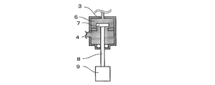
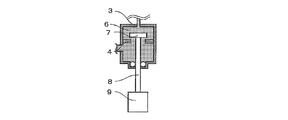
- FIGS. 2A to 2E are diagrams for explaining the operation of the valve device 1
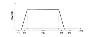
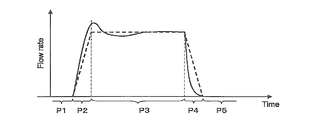
- FIG. 3 is a graph showing a time-series change in the flow rate of the fluid 6 flowing out from the outlet 3 of the valve device 1.
- the actuator 9 is often provided outside the valve box 5.
- the valve shaft 8 is inserted through a through hole 10 formed in the wall of the valve box 5.
- the valve device 1 includes a seal member 11 that closes a gap between the valve shaft 8 and the through hole 10 such as an O-ring or a V packing.
- FIG. 4 is an enlarged cross-sectional view of the vicinity of the through hole 10 of the valve device 1 in which an O-ring is used as the seal member 11.
- valve shaft 8 and the seal member 11 are in contact with each other. Therefore, the valve shaft 8 and the seal member 11 are easily worn by the movement of the valve shaft 8. . Wear debris generated by wear of the valve shaft 8 and the seal member 11 may be mixed in the fluid 6 and the fluid containing the wear debris may flow out from the outlet 3.
- Patent Document 1 JP 2011-33074 A discloses an example of a valve device that uses a flexible film such as a diaphragm as the seal member 11. It is disclosed.
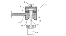
- FIG. 5 is a schematic view of the valve device 12 using a flexible membrane as a seal member.
- symbol is attached
- the valve device 12 includes a flexible film 13 disposed in the through hole 10.
- a hole is formed in the flexible membrane 13, and the valve shaft 8 is inserted through the hole.
- the periphery of the hole of the flexible membrane 13 is fixed to the outer periphery of the valve shaft 8, and the outer peripheral end of the flexible membrane 13 is fixed to the periphery of the through-hole 10.
- FIG. 6 is a graph showing a time-series change in the flow rate of the fluid 6 from the outlet 3 of the valve device 12.
- the solid line shows the change in the flow rate of the valve device 12 (FIG. 5) in which the through-hole 10 is blocked using the flexible membrane 13, and the chain line shows the through-hole 10 using the O-ring.
- a change in the flow rate of the blocked valve device 1 (FIG. 1) is shown.
- valve shaft 8 When the valve shaft 8 is moved in a direction in which the opening of the valve seat 4 is opened, that is, when the valve shaft 8 is moved in a direction in which the valve shaft 8 is pushed into the valve box 5, the flexible membrane 13 is also in the valve box. The volume of the valve box 5 is reduced. Therefore, the fluid 6 that has accumulated in the valve box 5 flows out from the outlet 3 by a decrease in the volume of the valve box 5. As a result, the flow rate of the valve device 12 (FIG. 5) in the period P2 was larger than that of the valve device 1 (FIG. 1).
- valve shaft 8 when the valve shaft 8 is moved in the direction of closing the opening of the valve seat 4, the flexible membrane 13 is pulled out from the valve box 5, and the volume of the valve box 5 increases. Therefore, a part of the fluid 6 sent from a pump (not shown) stays in the valve box 5. As a result, the flow rate of the valve device 12 (FIG. 5) in the period P4 was smaller than that of the valve device 1 (FIG. 1).
- an example of the object of the present invention is to provide a valve device that can suppress fluctuations in the flow rate without causing wear of the valve shaft into the fluid.
- one aspect of the present invention includes a valve box, a valve stem, a first flexible film, and a second flexible film.
- the valve box has an inflow port and an outflow port, and forms a space for containing a fluid therein.
- the valve shaft is inserted into a through hole formed in the wall of the valve box, and moves in the length direction of the through hole, thereby blocking a flow of fluid flowing into the space from the inlet and flowing out of the outlet. Move your body.
- the first flexible membrane has an insertion hole through which the valve shaft is inserted.
- the outer peripheral end of the first flexible membrane is fixed to the periphery of the through hole of the valve box, and the peripheral edge of the insertion hole of the first flexible membrane is fixed to the outer periphery of the valve shaft, The gap between the valve shaft and the valve shaft is blocked.
- the second flexible membrane forms part of the wall of the valve box.
- valve device of the present invention it is possible to suppress fluctuations in the flow rate without causing wear of the valve shaft into the fluid.
- FIG. 1 It is a graph which shows the time-sequential change of the flow volume of the fluid which flows out from the outflow port of the valve apparatus shown by FIG. 1 is a schematic view of a valve device according to a first embodiment of the present invention. It is the schematic which shows the closed state of the valve apparatus shown in FIG. It is the schematic which shows the open state of the valve apparatus shown in FIG. It is the schematic which shows the closed state of the valve apparatus which concerns on the 2nd Example of this invention. It is the schematic which shows the open state of the valve apparatus which concerns on the 2nd Example of this invention. It is the schematic of the valve apparatus which used the rack and pinion mechanism as a deformation
- valve device according to an embodiment of the present invention will be described in detail based on the drawings. Note that, among the constituent elements of the valve device according to the embodiment of the present invention, the same constituent elements as those shown in FIGS. 1 and 5 are denoted by the same reference numerals, and the description thereof is omitted.
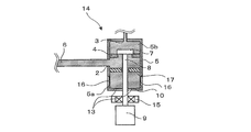
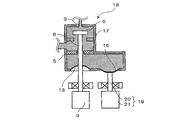
- FIG. 7 is a schematic view of the valve device according to the first embodiment of the present invention.
- the valve device 14 of the present embodiment includes an inflow port 2 and an outflow port 3, and includes a valve box 5 that forms a space for accommodating the fluid 6.
- a valve seat 4 having an opening is disposed in the valve box 5, and the fluid 6 flowing in from the inlet 2 flows to the outlet 3 through the opening.
- valve device 14 includes a valve body 7 that opens and closes the opening of the valve seat 4 inside the valve box 5. When the opening of the valve seat 4 is closed, the flow of the fluid 6 that flows into the space in the valve box 5 from the inlet 2 and flows out from the outlet 3 is blocked.
- the valve body 7 is connected to an actuator 9 provided outside the valve box 5 via a valve shaft 8.
- an actuator 9 moves the valve body 7, the opening of the valve seat 4 is opened and closed.
- an air cylinder or a motor can be used as the actuator 9, an air cylinder or a motor.
- a state where the opening of the valve seat 4 is closed is referred to as a closed state
- a state where the opening is open is referred to as an open state
- valve shaft 8 is inserted through a through hole 10 formed in the wall of the valve box 5.
- a valve shaft guide 15 is provided around the valve shaft 8 located outside the valve box 5. The moving direction of the valve shaft 8 is regulated by the valve shaft guide 15 in the length direction of the through hole 10.
- the first through hole 10 is provided with a first flexible film 13 such as a diaphragm.
- the first flexible membrane 13 is formed with an insertion hole through which the valve shaft 8 is inserted.
- the outer peripheral end of the first flexible membrane 13 is fixed to the periphery of the through hole 10, and the periphery of the insertion hole of the first flexible membrane 13 is fixed to the outer periphery of the valve shaft 8. Therefore, the gap between the through hole 10 and the valve shaft 8 is completely closed by the first flexible film 13.
- Part of the wall of the valve box 5 is formed by a second flexible film 16 that is different from the first flexible film 13.
- a diaphragm can be used as the second flexible film 16.
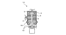
- FIG. 8A is a schematic view of the valve device 14 in the closed state
- FIG. 8B is a schematic view of the valve device 14 in the open state.
- valve shaft 8 moves in a direction to be pushed into the valve box 5. Since the first flexible film 13 is fixed to the valve shaft 8, the first flexible film 13 is also pushed into the valve box 5 as the valve shaft 8 moves. That is, the first flexible membrane 13 is deformed in a direction that reduces the volume of the valve box 5.
- the pressure of the fluid 6 in the valve box 5 increases.
- the second flexible membrane 16 is deformed in the direction of being pulled out from the valve box 5, that is, in the direction of increasing the volume of the valve box 5. Since the first flexible membrane 13 is deformed in the direction of decreasing the volume of the valve box 5 and the twenty-second flexible membrane 16 is deformed in the direction of increasing the volume of the valve box 5, the volume of the valve box 5 is increased. Hardly fluctuates.
- valve shaft 8 moves in the direction of being pulled out from the valve box 5, and the first flexible membrane 13 increases the volume of the valve box 5. Deform.
- the pressure of the fluid 6 in the valve box 5 decreases.
- the second flexible film 16 is deformed in a direction in which the second flexible film 16 is pushed into the valve box 5, that is, in a direction in which the volume of the valve box 5 is reduced. Since the first flexible membrane 13 is deformed in a direction to increase the volume of the valve box 5, and the twenty-second flexible membrane 16 is deformed in a direction to decrease the volume of the valve box 5, the volume of the valve box 5 is Hardly fluctuates.
- valve device 14 even when the valve shaft 8 moves in the direction pushed into the valve box 5 or when the valve shaft 8 moves in the direction pulled out from the valve box 5, the volume of the valve box 5 Does not change. Therefore, in the valve device 14 according to the present embodiment, even if the valve shaft 8 moves, the flow rate of the fluid 6 flowing out from the outlet 3 of the valve device 14 hardly varies.
- the first chamber 5 a is formed by the wall of the valve box 5 including the first and second flexible films 13 and 16 and the partition plate 17.
- the second chamber 5 b is formed by the wall of the valve box 5 including the inlet 2 and the outlet 3 and the partition plate 17.
- the second flexible membrane 16 is deformed in the direction of being pulled out from the valve box 5.
- the pressure of the fluid 6 in the first chamber 5a decreases and returns to the original value. That is, even if the first flexible film 13 is deformed, the pressure of the fluid 6 in the first chamber 5a hardly changes.
- the first chamber 5a and the second chamber 5b are partitioned by the partition plate 17, even if the first flexible membrane 13 is deformed in the direction in which it is pushed into the valve box 5, the fluid in the first chamber 5a 6 hardly flows toward the second chamber 5b. That is, the fluctuation of the pressure of the fluid 6 in the first chamber 5a is not easily transmitted to the second chamber 5b. Therefore, the fluctuation
- the gap between the hole of the partition plate 17 and the valve shaft 8 is preferably large enough to prevent the fluctuation of the pressure of the fluid 6 in the first chamber 5a from being transmitted to the second chamber 5b, for example, about 100 ⁇ m.
- the second flexible film 16 is designed with a material and dimensions that are more easily deformed than the first flexible film 13.
- the second flexible film 16 is formed using a material having a smaller elastic modulus than the material forming the first flexible film 13, or the area of the second flexible film 16 is set to the first value. Or larger than the area of the flexible film 13.
- the second flexible membrane 16 is likely to be deformed in response to fluctuations in the pressure of the fluid 6 in the valve box 5 due to the deformation of the first flexible membrane 13, and the pressure Fluctuations can be suppressed. As a result, fluctuations in the flow rate of the fluid 6 from the outlet 3 of the valve device 14 are further suppressed.
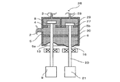
- FIG. 9A is a schematic diagram illustrating a closed state of the valve device 18 according to the present embodiment
- FIG. 9B is a schematic diagram illustrating an open state of the valve device 18.
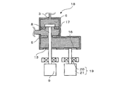
- a pinion 24 is provided between the first and second racks 22 and 23, and the movement of the first rack 22 is transmitted to the second rack 23 via the pinion 24. Therefore, the second rack 23 is moved and the second flexible film 16 is deformed as the valve shaft 8 is moved, that is, the first flexible film 13 is deformed.
- the actuator 21 is connected to a control means (not shown), and moves the bar member 20 in conjunction with the operation of the actuator 9.
Landscapes
- Engineering & Computer Science (AREA)
- General Engineering & Computer Science (AREA)
- Mechanical Engineering (AREA)
- Details Of Valves (AREA)
- Fluid-Driven Valves (AREA)
- Sliding Valves (AREA)
- Lift Valve (AREA)
Priority Applications (4)
| Application Number | Priority Date | Filing Date | Title |
|---|---|---|---|
| US14/346,953 US9388911B2 (en) | 2011-09-26 | 2012-09-03 | Valve apparatus |
| JP2013536108A JP5664793B2 (ja) | 2011-09-26 | 2012-09-03 | バルブ装置 |
| CN201280046674.4A CN103827561B (zh) | 2011-09-26 | 2012-09-03 | 阀装置 |
| IN3009CHN2014 IN2014CN03009A (cg-RX-API-DMAC7.html) | 2011-09-26 | 2012-09-03 |
Applications Claiming Priority (4)
| Application Number | Priority Date | Filing Date | Title |
|---|---|---|---|
| JP2011-208498 | 2011-09-26 | ||
| JP2011208498 | 2011-09-26 | ||
| JP2012-169939 | 2012-07-31 | ||
| JP2012169939 | 2012-07-31 |
Publications (1)
| Publication Number | Publication Date |
|---|---|
| WO2013047096A1 true WO2013047096A1 (ja) | 2013-04-04 |
Family
ID=47995143
Family Applications (1)
| Application Number | Title | Priority Date | Filing Date |
|---|---|---|---|
| PCT/JP2012/072349 Ceased WO2013047096A1 (ja) | 2011-09-26 | 2012-09-03 | バルブ装置 |
Country Status (5)
| Country | Link |
|---|---|
| US (1) | US9388911B2 (cg-RX-API-DMAC7.html) |
| JP (1) | JP5664793B2 (cg-RX-API-DMAC7.html) |
| CN (1) | CN103827561B (cg-RX-API-DMAC7.html) |
| IN (1) | IN2014CN03009A (cg-RX-API-DMAC7.html) |
| WO (1) | WO2013047096A1 (cg-RX-API-DMAC7.html) |
Cited By (1)
| Publication number | Priority date | Publication date | Assignee | Title |
|---|---|---|---|---|
| JP2022043963A (ja) * | 2020-09-04 | 2022-03-16 | アドバンス電気工業株式会社 | 定圧弁 |
Families Citing this family (1)
| Publication number | Priority date | Publication date | Assignee | Title |
|---|---|---|---|---|
| JP7107291B2 (ja) * | 2019-09-10 | 2022-07-27 | 株式会社デンソー | バルブ装置、流体循環回路 |
Citations (6)
| Publication number | Priority date | Publication date | Assignee | Title |
|---|---|---|---|---|
| JPS5522596U (cg-RX-API-DMAC7.html) * | 1978-08-01 | 1980-02-13 | ||
| JPH09245507A (ja) * | 1996-03-05 | 1997-09-19 | Stanley Electric Co Ltd | 空気圧維持装置およびそれを用いた灯具 |
| JP2004185831A (ja) * | 2002-11-29 | 2004-07-02 | Keihin Corp | 燃料電池用レギュレータユニット |
| JP2006138401A (ja) * | 2004-11-12 | 2006-06-01 | Nissan Motor Co Ltd | 静電駆動型マイクロバルブ |
| JP2010255831A (ja) * | 2009-04-28 | 2010-11-11 | Bridgestone Corp | 防振装置 |
| JP2011033074A (ja) * | 2009-07-30 | 2011-02-17 | Asahi Sunac Corp | ダイヤフラムバルブ |
Family Cites Families (14)
| Publication number | Priority date | Publication date | Assignee | Title |
|---|---|---|---|---|
| US3638670A (en) * | 1970-03-25 | 1972-02-01 | Westinghouse Air Brake Co | Low to high fluid pressure interface apparatus |
| JPS5012540B2 (cg-RX-API-DMAC7.html) * | 1972-07-31 | 1975-05-13 | ||
| US3991788A (en) * | 1975-08-28 | 1976-11-16 | Coffee-Mat Corporation | Fluid flow distributor for multi-choice vending machine |
| JPS5851174B2 (ja) | 1978-05-12 | 1983-11-15 | 松下電器産業株式会社 | 空調装置 |
| JPS6085679U (ja) | 1983-11-14 | 1985-06-13 | エヌオーケー株式会社 | バルブ |
| JPS6345470U (cg-RX-API-DMAC7.html) | 1986-09-12 | 1988-03-26 | ||
| JPS63106478A (ja) | 1986-10-24 | 1988-05-11 | Fuji Photo Film Co Ltd | 電磁弁 |
| JPH10259764A (ja) * | 1997-03-18 | 1998-09-29 | Unisia Jecs Corp | 排気還流制御装置 |
| US6623256B2 (en) * | 2001-02-21 | 2003-09-23 | Seiko Epson Corporation | Pump with inertance value of the entrance passage being smaller than an inertance value of the exit passage |
| JP4179114B2 (ja) * | 2003-09-09 | 2008-11-12 | 三菱ふそうトラック・バス株式会社 | 異物侵入防止構造付き流体装置 |
| JP4350105B2 (ja) | 2006-06-12 | 2009-10-21 | 武蔵エンジニアリング株式会社 | 液体定量吐出バルブおよび液体定量吐出装置 |
| JP4903063B2 (ja) * | 2007-02-02 | 2012-03-21 | 旭有機材工業株式会社 | マニホールド弁 |
| CN201206642Y (zh) * | 2008-05-23 | 2009-03-11 | 天津市仕科科贸有限公司 | 真空集便系统的冲洗阀 |
| CN101725720A (zh) * | 2008-11-03 | 2010-06-09 | 大连八方经济技术有限公司 | 隔膜式稳压微调阀门 |
-
2012
- 2012-09-03 IN IN3009CHN2014 patent/IN2014CN03009A/en unknown
- 2012-09-03 CN CN201280046674.4A patent/CN103827561B/zh active Active
- 2012-09-03 WO PCT/JP2012/072349 patent/WO2013047096A1/ja not_active Ceased
- 2012-09-03 JP JP2013536108A patent/JP5664793B2/ja active Active
- 2012-09-03 US US14/346,953 patent/US9388911B2/en active Active
Patent Citations (6)
| Publication number | Priority date | Publication date | Assignee | Title |
|---|---|---|---|---|
| JPS5522596U (cg-RX-API-DMAC7.html) * | 1978-08-01 | 1980-02-13 | ||
| JPH09245507A (ja) * | 1996-03-05 | 1997-09-19 | Stanley Electric Co Ltd | 空気圧維持装置およびそれを用いた灯具 |
| JP2004185831A (ja) * | 2002-11-29 | 2004-07-02 | Keihin Corp | 燃料電池用レギュレータユニット |
| JP2006138401A (ja) * | 2004-11-12 | 2006-06-01 | Nissan Motor Co Ltd | 静電駆動型マイクロバルブ |
| JP2010255831A (ja) * | 2009-04-28 | 2010-11-11 | Bridgestone Corp | 防振装置 |
| JP2011033074A (ja) * | 2009-07-30 | 2011-02-17 | Asahi Sunac Corp | ダイヤフラムバルブ |
Cited By (2)
| Publication number | Priority date | Publication date | Assignee | Title |
|---|---|---|---|---|
| JP2022043963A (ja) * | 2020-09-04 | 2022-03-16 | アドバンス電気工業株式会社 | 定圧弁 |
| JP7588396B2 (ja) | 2020-09-04 | 2024-11-22 | アドバンス電気工業株式会社 | 定圧弁 |
Also Published As
| Publication number | Publication date |
|---|---|
| JPWO2013047096A1 (ja) | 2015-03-26 |
| IN2014CN03009A (cg-RX-API-DMAC7.html) | 2015-07-03 |
| JP5664793B2 (ja) | 2015-02-04 |
| US9388911B2 (en) | 2016-07-12 |
| CN103827561A (zh) | 2014-05-28 |
| CN103827561B (zh) | 2016-01-06 |
| US20140239213A1 (en) | 2014-08-28 |
Similar Documents
| Publication | Publication Date | Title |
|---|---|---|
| JP6450499B2 (ja) | 電子膨張弁 | |
| CN107366772A (zh) | 电动阀 | |
| JP2019504253A (ja) | 2段階式電子膨張弁 | |
| WO2009019264A3 (de) | Ausströmventil für ein luftfahrzeug | |
| CN106415025B (zh) | 伺服阀 | |
| EP3054201B1 (en) | Self-acting pressure drain valve | |
| JP2005256836A (ja) | フィルタのための2ピース構造のエラストマ製リリーフ弁及び耐ドレインバック弁 | |
| US20170218984A1 (en) | Cylinder device | |
| JP5664793B2 (ja) | バルブ装置 | |
| JP7065828B2 (ja) | 電磁比例弁 | |
| CN104879523A (zh) | 阀门及其使用方法 | |
| JP5614717B2 (ja) | バルブ | |
| GB2582747A (en) | Device for controlling fluid flow | |
| RU2498136C2 (ru) | Устройство для управления потоком с использованием диафрагмы | |
| HU229976B1 (hu) | Dugattyúszerkezet és ezzel kialakított folyadékadagoló szelep | |
| US11060631B2 (en) | Servovalve | |
| JP2017155910A (ja) | 流体制御弁 | |
| FI119853B (fi) | Ovensuljin | |
| CN106062651A (zh) | 减压阀 | |
| JP2008014492A (ja) | カートリッジ弁組立体 | |
| WO2018047647A1 (ja) | 減衰弁およびシリンダ装置 | |
| EP3115620A1 (en) | Cylinder device | |
| CN103429910A (zh) | 阀 | |
| KR200444007Y1 (ko) | 밸브 어셈블리 | |
| JP6217720B2 (ja) | 電磁弁 |
Legal Events
| Date | Code | Title | Description |
|---|---|---|---|
| 121 | Ep: the epo has been informed by wipo that ep was designated in this application |
Ref document number: 12836788 Country of ref document: EP Kind code of ref document: A1 |
|
| ENP | Entry into the national phase |
Ref document number: 2013536108 Country of ref document: JP Kind code of ref document: A |
|
| WWE | Wipo information: entry into national phase |
Ref document number: 14346953 Country of ref document: US |
|
| NENP | Non-entry into the national phase |
Ref country code: DE |
|
| 122 | Ep: pct application non-entry in european phase |
Ref document number: 12836788 Country of ref document: EP Kind code of ref document: A1 |