WO2013046833A1 - 画像表示装置及びその視差調整表示方法並びに画像撮像装置 - Google Patents
画像表示装置及びその視差調整表示方法並びに画像撮像装置 Download PDFInfo
- Publication number
- WO2013046833A1 WO2013046833A1 PCT/JP2012/066254 JP2012066254W WO2013046833A1 WO 2013046833 A1 WO2013046833 A1 WO 2013046833A1 JP 2012066254 W JP2012066254 W JP 2012066254W WO 2013046833 A1 WO2013046833 A1 WO 2013046833A1
- Authority
- WO
- WIPO (PCT)
- Prior art keywords
- image
- display
- images
- display device
- subject
- Prior art date
- Legal status (The legal status is an assumption and is not a legal conclusion. Google has not performed a legal analysis and makes no representation as to the accuracy of the status listed.)
- Ceased
Links
Images





Classifications
-
- H—ELECTRICITY
- H04—ELECTRIC COMMUNICATION TECHNIQUE
- H04N—PICTORIAL COMMUNICATION, e.g. TELEVISION
- H04N13/00—Stereoscopic video systems; Multi-view video systems; Details thereof
- H04N13/30—Image reproducers
- H04N13/302—Image reproducers for viewing without the aid of special glasses, i.e. using autostereoscopic displays
-
- G—PHYSICS
- G03—PHOTOGRAPHY; CINEMATOGRAPHY; ANALOGOUS TECHNIQUES USING WAVES OTHER THAN OPTICAL WAVES; ELECTROGRAPHY; HOLOGRAPHY
- G03B—APPARATUS OR ARRANGEMENTS FOR TAKING PHOTOGRAPHS OR FOR PROJECTING OR VIEWING THEM; APPARATUS OR ARRANGEMENTS EMPLOYING ANALOGOUS TECHNIQUES USING WAVES OTHER THAN OPTICAL WAVES; ACCESSORIES THEREFOR
- G03B15/00—Special procedures for taking photographs; Apparatus therefor
-
- G—PHYSICS
- G03—PHOTOGRAPHY; CINEMATOGRAPHY; ANALOGOUS TECHNIQUES USING WAVES OTHER THAN OPTICAL WAVES; ELECTROGRAPHY; HOLOGRAPHY
- G03B—APPARATUS OR ARRANGEMENTS FOR TAKING PHOTOGRAPHS OR FOR PROJECTING OR VIEWING THEM; APPARATUS OR ARRANGEMENTS EMPLOYING ANALOGOUS TECHNIQUES USING WAVES OTHER THAN OPTICAL WAVES; ACCESSORIES THEREFOR
- G03B17/00—Details of cameras or camera bodies; Accessories therefor
- G03B17/18—Signals indicating condition of a camera member or suitability of light
-
- G—PHYSICS
- G03—PHOTOGRAPHY; CINEMATOGRAPHY; ANALOGOUS TECHNIQUES USING WAVES OTHER THAN OPTICAL WAVES; ELECTROGRAPHY; HOLOGRAPHY
- G03B—APPARATUS OR ARRANGEMENTS FOR TAKING PHOTOGRAPHS OR FOR PROJECTING OR VIEWING THEM; APPARATUS OR ARRANGEMENTS EMPLOYING ANALOGOUS TECHNIQUES USING WAVES OTHER THAN OPTICAL WAVES; ACCESSORIES THEREFOR
- G03B35/00—Stereoscopic photography
- G03B35/08—Stereoscopic photography by simultaneous recording
- G03B35/10—Stereoscopic photography by simultaneous recording having single camera with stereoscopic-base-defining system
-
- H—ELECTRICITY
- H04—ELECTRIC COMMUNICATION TECHNIQUE
- H04N—PICTORIAL COMMUNICATION, e.g. TELEVISION
- H04N13/00—Stereoscopic video systems; Multi-view video systems; Details thereof
- H04N13/20—Image signal generators
- H04N13/204—Image signal generators using stereoscopic image cameras
-
- H—ELECTRICITY
- H04—ELECTRIC COMMUNICATION TECHNIQUE
- H04N—PICTORIAL COMMUNICATION, e.g. TELEVISION
- H04N13/00—Stereoscopic video systems; Multi-view video systems; Details thereof
- H04N13/20—Image signal generators
- H04N13/204—Image signal generators using stereoscopic image cameras
- H04N13/239—Image signal generators using stereoscopic image cameras using two two-dimensional [2D] image sensors having a relative position equal to or related to the interocular distance
-
- H—ELECTRICITY
- H04—ELECTRIC COMMUNICATION TECHNIQUE
- H04N—PICTORIAL COMMUNICATION, e.g. TELEVISION
- H04N13/00—Stereoscopic video systems; Multi-view video systems; Details thereof
- H04N13/20—Image signal generators
- H04N13/296—Synchronisation thereof; Control thereof
-
- H—ELECTRICITY
- H04—ELECTRIC COMMUNICATION TECHNIQUE
- H04N—PICTORIAL COMMUNICATION, e.g. TELEVISION
- H04N23/00—Cameras or camera modules comprising electronic image sensors; Control thereof
- H04N23/60—Control of cameras or camera modules
- H04N23/61—Control of cameras or camera modules based on recognised objects
-
- H—ELECTRICITY
- H04—ELECTRIC COMMUNICATION TECHNIQUE
- H04N—PICTORIAL COMMUNICATION, e.g. TELEVISION
- H04N23/00—Cameras or camera modules comprising electronic image sensors; Control thereof
- H04N23/60—Control of cameras or camera modules
- H04N23/61—Control of cameras or camera modules based on recognised objects
- H04N23/611—Control of cameras or camera modules based on recognised objects where the recognised objects include parts of the human body
-
- H—ELECTRICITY
- H04—ELECTRIC COMMUNICATION TECHNIQUE
- H04N—PICTORIAL COMMUNICATION, e.g. TELEVISION
- H04N23/00—Cameras or camera modules comprising electronic image sensors; Control thereof
- H04N23/60—Control of cameras or camera modules
- H04N23/63—Control of cameras or camera modules by using electronic viewfinders
- H04N23/633—Control of cameras or camera modules by using electronic viewfinders for displaying additional information relating to control or operation of the camera
- H04N23/635—Region indicators; Field of view indicators
-
- H—ELECTRICITY
- H04—ELECTRIC COMMUNICATION TECHNIQUE
- H04N—PICTORIAL COMMUNICATION, e.g. TELEVISION
- H04N23/00—Cameras or camera modules comprising electronic image sensors; Control thereof
- H04N23/60—Control of cameras or camera modules
- H04N23/69—Control of means for changing angle of the field of view, e.g. optical zoom objectives or electronic zooming
Definitions
- the present invention relates to an image display device, a parallax adjustment display method thereof, and an image imaging device, and more particularly to an image display device excellent in usability for a user, a parallax adjustment display method thereof, and an image imaging device.
- a stereoscopic camera such as a stereo camera that captures a stereoscopic image
- the two-dimensional image for the right eye and the two-dimensional image for the left eye of the same subject viewed simultaneously with the right eye and the left eye, that is, two viewpoints are different (with parallax).
- a stereoscopic image of the subject is displayed by capturing a two-dimensional image and alternately displaying them on a display unit on the back of the camera frame by frame.
- This stereoscopic image is also displayed by two captured images with parallax that are output for the through image from the image sensor before the user presses the shutter button.
- the stereoscopic image display system described in Patent Document 1 described below describes the display of a stereoscopic image, but does not describe the user interface part for parallax adjustment.
- the stereoscopic image display system described in Patent Document 2 describes a technique for performing parallax adjustment, it has a user interface that can be easily understood at the shooting site and how the parallax adjustment affects the shot image. Absent.
- An object of the present invention is to provide an image display method, a parallax adjustment display method, and an image pickup apparatus that include a user interface that allows a camera user to perform parallax adjustment intuitively, easily, and clearly at a shooting site.
- An image display device, a parallax adjustment display method thereof, and an image pickup device of the present invention include a stereoscopic image acquisition unit that acquires a plurality of images with different viewpoints, and a display that displays the plurality of images acquired by the stereoscopic image acquisition unit.
- An image display device, a parallax adjustment display method thereof, and an image imaging device each of which includes: When capturing a stereoscopic image of a line in which the parallax amount between the first viewpoint image and the second viewpoint image in the plurality of images is zero, a line in which the parallax amount is zero, and the position of the specific subject
- the front-rear relationship in the optical axis direction is displayed on a partial display area of the display unit in a pseudo overhead view in which the subject is viewed from above with respect to the optical axis at the time of photographing the stereoscopic image.
- the present invention it is possible to know the degree of parallax adjustment from the context of the zero parallax amount line and the position of the specific subject by looking at the pseudo overhead view.
- FIG. 1 is an external perspective view of an image pickup apparatus (stereoscopic camera) according to an embodiment of the present invention. It is a functional block block diagram of the stereo camera shown in FIG. It is a figure which shows the example of a display image of the display part provided in the stereo camera back surface of FIG. It is a flowchart which shows the parallax adjustment processing procedure which concerns on 1st Embodiment of this invention. It is explanatory drawing of the pseudo overhead view (radar chart) which concerns on 1st Embodiment of this invention.
- FIG. 6 is an enlarged explanatory diagram of the radar chart shown in FIG. 5. It is a figure which shows the example of a display image of a display part after performing parallax adjustment from the state of the left figure of FIG.
- FIG. 1 is an external perspective view of a stereoscopic image pickup apparatus (in this embodiment, a digital camera for stereoscopic images of two left and right eyes, hereinafter referred to as a stereoscopic camera or simply a camera).
- the stereoscopic camera 10 is provided on a box-shaped housing 11, a right-eye imaging unit 12 ⁇ / b> R and a left-eye imaging unit 12 ⁇ / b> L provided side by side on the front of the housing 11, and a front left shoulder portion of the housing 11.
- the flashlight 13 includes a power switch 14, a shutter button 15, and a mode selection dial 16 provided at appropriate positions on the upper surface of the housing 11.
- liquid crystal display unit 29 shown in FIG. 2, and a through image, a mode selection screen, a menu screen, a guide display, and the like are displayed.
- a lenticular lens sheet (not shown) is pasted on the liquid crystal display unit 29 so that a stereoscopic image can be displayed.
- the imaging unit 12R includes a photographic lens 21R at the front
- the imaging unit 12L includes a photographic lens 21L at the front.
- An angle at which the optical axis 22R of the photographic lens 21R and the optical axis 22L of the photographic lens 21L intersect is called a convergence angle
- an actuator that controls the direction in which each of the imaging units 12R and 12L faces so that the convergence angle becomes a target value Lens control units 30L and 30R, which will be described later, are built in the stereoscopic camera 10.
- the stereoscopic effect of the stereoscopic image can also be controlled by fixing the convergence angle between the photographing lenses 21R and 21L and adjusting the left and right deviation amounts of the left and right captured images with an image processing technique.
- the photographing lenses 21R and 21L can independently adjust the focus position and the zoom magnification. However, in the stereo photographing mode, the photographing lenses 21R and 21L are controlled in conjunction so that a stereoscopic image of the subject can be photographed. It has become.
- FIG. 2 is an internal functional block diagram of the stereoscopic camera 10 shown in FIG.
- a solid-state image sensor 23L is disposed on the back of the photographic lens 21L
- a solid-state image sensor 23R is disposed on the back of the photographic lens 21R.
- the output signals of the solid-state image sensors 23L and 23R are connected to AFE (analog front end) circuits 24L and 24R, respectively, and the outputs of the AFE circuits 24L and 24R are connected to the bus 25.
- AFE analog front end
- a CPU (system control unit) 26, a memory 27, an image processing unit (DSP) 28, and a liquid crystal display unit 29 are connected to the bus 25.
- the image processing unit 28 performs known image processing such as offset processing, gamma correction processing, RGB / YC conversion processing, and synchronization processing, and takes captured image data in an external memory such as a memory card (not shown). Record.
- Lens control units 30L and 30R are connected to the CPU 26.
- the lens control unit 30L controls the focal position control and zoom magnification control of the photographing lens 21L according to instructions from the CPU 26.
- the lens control unit 30R receives control from the CPU 26.
- focus position control and zoom magnification control of the taking lens 21R are performed independently of the taking lens 21L.
- the lens control units 30L and 30R interlock control the photographing lenses 21L and 21R to the same magnification and the same focal position according to an instruction from the CPU 26.
- the CPU 26 has a subject selection function for selecting a specific subject among the subjects. For example, a focused subject, a subject detected by object detection such as face detection, or a subject having a spatial frequency (edge) equal to or greater than a threshold is selected as a specific subject. Alternatively, when a touch panel is attached to the liquid crystal display unit 29, the CPU 26 selects a subject designated by the touch operation by the user as a specific subject.
- FIG. 3 is a diagram showing an example of a display screen of the liquid crystal display unit 29 provided on the back of the camera.
- the person image 41 is in focus, and two car images 42 and 43 are shown on the other side.
- FIG. 4 is a flowchart showing a parallax adjustment processing procedure executed by the CPU 26 of FIG. 2 in response to an instruction input from the user.
- this process is started, first, in step S1, each of the images (the two-dimensional image for the left eye captured by the solid-state image sensor 23L and the two-dimensional image for the right eye captured by the solid-state image sensor 23R) is displayed. Feature points are extracted.
- step S2 corresponding points between the feature points of the left and right images are calculated.
- step S1 feature points in the two-dimensional image for the left eye and feature points in the two-dimensional image for the right eye are extracted, but the feature point extraction algorithms for both images are the same, so both images are the same. Feature points will be extracted. That is, the correspondence between the same feature points in both images is calculated in step S2.
- the distance between the corresponding feature points is the amount of parallax.
- step S3 clustering is performed. That is, the feature points extracted in step S1 and associated in step S2 are clustered.
- a set of feature points belonging to the image 41, a set of feature points belonging to the image 42, and an image 43 Clustering of a set of feature points belonging to is performed, and thereafter the feature points are managed for each subject image.
- step S4 the distance from the camera to each feature point (a set thereof) is calculated, and in step S5, the distance from the camera 10 to zero parallax (hereinafter referred to as a cross point) is calculated.
- a cross point the distance from the camera 10 to zero parallax
- the CPU 26 displays a pseudo overhead view (hereinafter, also referred to as a radar chart, which will be described with reference to FIG. 5) of the subject (scene) being imaged from above with respect to the optical axis.
- a pseudo overhead view hereinafter, also referred to as a radar chart, which will be described with reference to FIG. 5
- a round frame, a square frame, a triangular frame, or the like is displayed so as to overlap each specific subject on the image of the specific subject in the display image, and these round frames are displayed instead of the subject image in the radar chart.
- a square frame, a triangular frame, or the like may be distinguished with a color) (step S7).
- the CPU 26 functions as a display control unit that displays in the partial display area of the liquid crystal display unit 29 on the radar chart 50 when the subject is viewed from above with respect to the optical axis at the time of stereoscopic image shooting.
- FIG. 5 is a diagram in which a round frame 41a, a square frame 42a, and a triangular frame 43a are superimposed and displayed on the specific subject images 41, 42, and 43 in the subject image of FIG. 3, respectively.
- the two-dimensional image for the left eye and the two-dimensional image for the right eye are displayed in an overlapping state.
- the two-dimensional image for the left eye and the two-dimensional image for the right eye are alternately displayed for each frame, and this is recognized as a three-dimensional image because it enters the eyes of the person viewing the display screen through the lenticular lens sheet. .
- a small window is opened in an empty area of the screen, for example, the lower right area, and the radar chart 50 is displayed in this window.
- FIG. 5 The right figure of FIG. 5 is an enlarged view of the radar chart 50.
- An arc-shaped thick line 51 in the figure indicates a line representing zero parallax.
- the line 51 representing zero parallax is referred to as a cross-point line.
- an icon (round frame) 41b indicating the image 41 is in front of the cross point line 51
- an icon (triangular frame) 43b indicating the image 43 is on the far side of the cross point line 51.
- a shaded arc region 52 in the figure indicates a range where stereoscopic viewing is possible.
- the approximate distance calculated by the camera is shown on the center line.
- step S8 it is determined in step S8 following step S7 whether or not a parallax adjustment operation has been performed.
- the parallax adjustment is performed by, for example, an operation for moving the left and right images closer to or away from each other (for example, specifying parallax adjustment and using an operation cross key or the like).
- step S8 the process proceeds from step S8 to step S9, and the distance from the camera 10 to the cross point after the parallax adjustment operation is recalculated.
- step S10 the display of the cross point line 51 is instructed to be updated.
- the stereoscopic viewable range 52 is recalculated (step S11), the display of the stereoscopic viewable range is instructed to update (step S12), and the radar chart 50 is updated by returning to step S6. Is displayed again. An enlarged view of the redisplayed radar chart 50 is shown in FIG. The cross point line is moved (arrow 54) so as to match the position of the icon 41b of the person image.
- the parallax adjustment changes the distance from the camera where the parallax amount becomes zero, and accordingly, the display position of the cross point line 51 on the radar chart 50 is moved. If the user wants to focus on the person image 41, the parallax adjustment may be performed on the radar chart 50 so that the cross point line 51 is positioned on the icon 41b corresponding to the person image 41.
- step S8 if there is no parallax adjustment operation, the process proceeds from step S8 to step S13, and it is determined whether or not there is a parallax adjustment end operation. If there is no end operation, the process returns to step S8. If there is an end operation, the parallax adjustment is ended (step S14), and the process ends.
- FIG. 7 is a diagram illustrating a screen display example after the parallax adjustment is completed.
- the left and right images of the human image 41 are misaligned.
- the parallax is zero in the human image 41. It matches the person image 41 in the dimensional image.
- the distance from the camera to each subject can be visually recognized by the display of the radar chart 50, the front-rear relationship between the cross point and each subject can be visually recognized, and the image can be displayed by jumping out from the screen. It is possible to clearly see the subject and the subject that is retracted and displayed. Furthermore, by displaying the stereoscopically viewable region 52, it is possible to make an adjustment while confirming the relative relationship between a plurality of subjects.
- the icon for each specific subject is displayed.
- the feature point may be displayed on the radar chart as some figure, and the object corresponding to the subject image (human shape) may be displayed on the radar chart. Or the shape of a building or car) may be displayed.
- FIG. 8 is a flowchart showing a parallax adjustment processing procedure according to another embodiment of the present invention.
- the photographing lens mounted on the camera 10 has a telephoto (zoom) lens function
- a zoom operation is performed, as shown in FIG. 9, a stereoscopically visible region changes, and a distant subject is stereoscopically viewed. It becomes possible. Therefore, in the present embodiment, a process for determining whether or not the angle of view is changed by a zoom operation is included.
- This embodiment of FIG. 8 differs from the embodiment of FIG. 4 in that a determination processing step S16 of “whether there is a zoom operation” is inserted between step S8 and step S13 in the flowchart of FIG. Since the processing steps are the same as those in FIG. 4, the same processing steps are denoted by the same step numbers and description thereof is omitted.
- step S16 when it is determined that there is no parallax adjustment operation in the determination process with the parallax adjustment operation in step S8, it is determined in step S16 whether there is a zoom operation. Then, when there is no zoom operation, the process proceeds to step S13 and proceeds to a determination process with the end operation.
- step S16 If it is determined that there is a zoom operation as a result of the determination process in step S16, the process returns to step S1, and the parallax adjustment process procedure is restarted from the beginning. As a result, as shown in FIG. 9, a radar chart 50 corresponding to the zoom amount is displayed, and the user can perform parallax adjustment according to the zoom amount.
- FIG. 10 is a flowchart showing a parallax adjustment processing procedure according to still another embodiment of the present invention.
- a digital camera when a user looks at a display image on the back of the camera to check whether or not it is in focus, for example, as described in Japanese Patent Application Laid-Open No. 2006-2222979, an enlarged image portion to be focused is displayed.
- Some devices have a function that allows the user to refocus.
- FIG. 10 is applied to a digital camera having such a focus confirmation function.
- the processing procedure of FIG. 10 is almost the same as the processing procedure of FIG. 4 except that a focus confirmation processing step S20 is provided between the processing step S7 and the processing step S8 of FIG. Therefore, the same step number is assigned to the same step, and the description thereof is omitted.
- the captured image is displayed on the liquid crystal display unit 29 on the back of the camera, the radar chart 50 is displayed in step S6, the icon corresponding to the specific subject image is displayed in step S7, and the process proceeds to the focus confirmation processing step S20.
- Step S20 as shown in FIG. 11, first, in Step S21, it is determined whether or not the user is confirming the focus by enlarging the focus area. If the focus area is not enlarged (if the determination result in step S21 is NO), the process proceeds to step S22, and it is determined whether or not there is an operation for instructing to enlarge the focus area. If the determination result is affirmative, enlargement display of the focus area is started in step S23, and the process proceeds to step S8 in FIG.
- the left figure of FIG. 12 is a diagram illustrating an enlarged view of the focus area.
- the person image 41 is enlarged and displayed, and the user can check whether the image is in focus by looking at the enlarged view of the image 41.
- the lines 56 and 57 indicating the range enlarged in the left diagram on the radar chart 50 may be distinguished from each other by, for example, a red line. In this way, the user can check the angle of view that is enlarged and displayed on the radar chart 50.
- step S21 If the result of the determination in step S21 is that the focus area has been enlarged and confirmed (the determination result is affirmative), the process proceeds to step S24, and this time, it is determined whether or not there is an end operation of the focus area expansion confirmation. . If the determination result is affirmative, the process proceeds to step S25, the enlarged display is terminated, and the process proceeds to step S8. Even when the determination results of steps S22 and S24 are negative, the process proceeds to step S8.
- the optical axes 22L and 22R of the photographic lenses 21L and 21R are fixed in the two-lens stereoscopic image capturing apparatus, and the parallax is controlled by controlling the number of pixels that shift each captured image in the horizontal direction.
- the angle of convergence can be controlled by adjusting the direction of the optical axes 22L and 22R of each photographing lens.
- the stereoscopic effect was changed by changing the amount of horizontal displacement of the two captured images, but this changes not only the through image but also the position where the parallax amount of the already captured stereoscopic image is zero. It can also be applied to cases.
- FIG. 8 and FIG. 10 have been described separately, it is needless to say that both of these embodiments can be implemented.
- the image display device includes a stereoscopic image acquisition unit that acquires a plurality of images with different viewpoints, a display unit that displays the plurality of images acquired by the stereoscopic image acquisition unit, and the plurality of images.
- a subject selection unit that selects a specific subject, a line in which the parallax amount between the first viewpoint image and the second viewpoint image in the plurality of images is zero, and the parallax amount is zero Between the line and the position of the specific subject in the direction of the optical axis at the time of stereoscopic image shooting, in the partial display area of the display unit, the subject from above with respect to the optical axis at the time of stereoscopic image shooting And a display control unit for displaying in a pseudo overhead view.
- the display control unit of the image display apparatus displays the image position of the specific subject as an icon on the pseudo overhead view.
- the display control unit of the image display device displays a stereoscopically visible region before and after the line where the parallax amount is zero on the pseudo overhead view.
- the display control unit of the image display device performs a parallax adjustment between the first viewpoint image and the second viewpoint image, and when the line where the parallax amount becomes zero is changed, The display of the pseudo overhead view is updated.
- the display control unit of the image display device when a confirmation operation of an enlarged image in a focus area for focusing on any of the subjects is performed, the pseudo overhead view corresponding to the enlarged image.
- the display of is updated.
- the display control unit of the image display device is characterized in that a distance is displayed on the pseudo overhead view.
- the parallax adjustment display method of the image display device includes a stereoscopic image acquisition unit that acquires a plurality of images with different viewpoints, a display unit that displays the plurality of images acquired by the stereoscopic image acquisition unit,
- a parallax adjustment display method of an image display device comprising: a subject selection unit that selects a specific subject in any of the plurality of images; When capturing a stereoscopic image of a line in which the parallax amount between the first viewpoint image and the second viewpoint image in the plurality of images is zero, a line in which the parallax amount is zero, and the position of the specific subject
- the front-rear relationship in the optical axis direction is displayed on a partial display area of the display unit in a pseudo overhead view in which the subject is viewed from above with respect to the optical axis at the time of photographing the stereoscopic image.
- the image capturing apparatus of the embodiment includes a stereoscopic image acquisition unit that acquires a plurality of images with different viewpoints, a display unit that displays the plurality of images acquired by the stereoscopic image acquisition unit, and a plurality of the images.
- a subject selection unit that selects a specific subject in any of the above, a line where the parallax amount between the first viewpoint image and the second viewpoint image in the plurality of images is zero, and the parallax amount is zero.
- the anteroposterior relationship between the line and the position of the specific subject in the optical axis direction at the time of stereoscopic image shooting is displayed in a partial display area of the display unit from above with respect to the optical axis at the time of stereoscopic image shooting.
- a display control unit for displaying in a pseudo overhead view.
- the image capturing apparatus includes a zoom lens, and the display control unit updates the display of the pseudo overhead view according to the zoom amount of the zoom lens when detecting the zoom operation of the zoom lens. It is characterized by that.
- a pseudo overhead view (radar chart) is displayed and the position of the parallax amount zero is changed by parallax adjustment. Therefore, the influence when the parallax is adjusted can be easily known, and the parallax adjustment can be performed. It becomes easy to do.
- the parallax adjustment display method it is possible to intuitively know how the stereoscopic effect of the stereoscopic image is affected when the parallax is adjusted.
- the present invention is useful when applied to an image display device incorporated in an imaging device, an image display device for processing stereoscopic image data by being taken into a personal computer or the like. Also in the image display device, information indicating that it is stereoscopic image data can be acquired from the header information of the image data, and processing similar to that of the above-described stereoscopic image imaging device is possible.
- Stereoscopic imaging device (stereoscopic camera) 15 Shutter button 21R, 21L Fishing lens 23L, 23R Image sensor (image sensor) 26 System controller (CPU) 28 Image Processing Unit (DSP) 29 Display unit 41, 42, 43 Image 41a, 42a, 43a of specific subject Frame shape 41b, 42b, 43b corresponding to specific subject Icon 50 Pseudo overhead view (radar chart) 51 Zero-parallax line (cross-point line) 52 Stereoscopic viewable area
Landscapes
- Engineering & Computer Science (AREA)
- Multimedia (AREA)
- Signal Processing (AREA)
- Physics & Mathematics (AREA)
- General Physics & Mathematics (AREA)
- Testing, Inspecting, Measuring Of Stereoscopic Televisions And Televisions (AREA)
- Studio Devices (AREA)
Abstract
視点の異なる複数の画像を取得する立体画像取得部と、立体画像取得部により取得された前記複数の画像を表示する表示部と、複数の画像のいずれかにおいて被写体の中の特定の被写体を選択する被写体選択部とを備える画像表示装置において、複数の画像の中の第1の視点画像と第2の視点画像との視差量がゼロとなるライン51と、視差量がゼロとなるライン51と特定の被写体41,42,43の位置との立体画像撮影時の光軸方向における前後関係とを、表示部の一部表示領域50に、立体画像撮影時の光軸に対し上方から被写体を見た擬似俯瞰図で表示する。
Description
本発明は、画像表示装置及びその視差調整表示方法並びに画像撮像装置に係り、特に、ユーザにとって使い勝手の優れた画像表示装置及びその視差調整表示方法並びに画像撮像装置に関する。
立体画像を撮像するステレオカメラ等の立体カメラでは、右眼と左眼で同時に見た同一被写体の右眼用二次元画像と左眼用二次元画像つまり2枚の視点の異なる(視差のある)二次元画像を撮像し、カメラ背面の表示部に両者を1フレーム毎に交互に表示することで、被写体の立体画像を表示している。この立体画像は、ユーザがシャッタボタンを押下する前に撮像素子からスルー画像用として出力される視差のある2つの撮像画像によっても表示される。
カメラユーザは、シャッタボタンを押下して被写体の立体画像を撮影するとき、カメラ背面表示部に表示されたスルー画の立体画像を見ながら視差を調整し、好みの立体感を得る立体画像の撮影をしたいと思うが、この視差の調整が難しく、カメラメーカ側にとってそのユーザインタフェースをどうするかが問題になっている。
下記の特許文献1に記載の立体画像表示システムは、立体画像の表示について記載はあるが、視差調整についてのユーザインタフェース部分の記載はない。特許文献2に記載の立体画像表示システムは、視差調整を行う技術について記載はあるが、撮影現場で容易にしかも視差調整が撮影画像にどの様に影響があるのか分かり易いユーザインタフェースにはなっていない。
本発明の目的は、カメラユーザが撮影現場で直感的かつ容易,明確に視差調整を行うことができるユーザインタフェースを備える画像表示方法及びその視差調整表示方法並びに画像撮像装置を提供することにある。
本発明の画像表示装置及びその視差調整表示方法並びに画像撮像装置は、視点の異なる複数の画像を取得する立体画像取得部と、前記立体画像取得部により取得された前記複数の画像を表示する表示部と、前記複数の画像のいずれかにおいて特定の被写体を選択する被写体選択部とを備える画像表示装置及びその視差調整表示方法並びに画像撮像装置において、
前記複数の画像の中の第1の視点画像と第2の視点画像との視差量がゼロとなるラインと、前記視差量がゼロとなるラインと前記特定の被写体の位置との立体画像撮影時の光軸方向における前後関係とを、前記表示部の一部表示領域に、前記立体画像撮影時の光軸に対し上方から前記被写体を見た擬似俯瞰図で表示することを特徴とする。
前記複数の画像の中の第1の視点画像と第2の視点画像との視差量がゼロとなるラインと、前記視差量がゼロとなるラインと前記特定の被写体の位置との立体画像撮影時の光軸方向における前後関係とを、前記表示部の一部表示領域に、前記立体画像撮影時の光軸に対し上方から前記被写体を見た擬似俯瞰図で表示することを特徴とする。
本発明によれば、擬似俯瞰図を見ることで、視差量ゼロのラインと、特定の被写体の位置とを、視差量ゼロのラインとの前後関係から視差調整の程度を知ることができる。
以下、本発明の一実施形態について、図面を参照して説明する。
図1は、立体画像撮像装置(本実施形態では左右2眼の立体画像用のデジタルカメラ、以下、立体カメラ又は単にカメラという。)の外観斜視図である。この立体カメラ10は、箱状のハウジング11と、ハウジング11の前部に並んで設けられた右眼用の撮像部12R及び左眼用の撮像部12Lと、ハウジング11の前面左肩部に設けられたフラッシュライト13と、ハウジング11の上面の適宜箇所に設けられた電源スイッチ14,シャッタボタン15,モード選択ダイヤル16とを備える。
ハウジング11の背面側には、図2に示す液晶表示部(モニタ)29を備え、スルー画像やモード選択画面,メニュー画面,ガイド表示等が表示される。液晶表示部29には、図示しないレンチキュラレンズシートが貼られており、立体画像の表示が可能となっている。
撮像部12Rは前部に撮影レンズ21Rを備え、撮像部12Lは前部に撮影レンズ21Lを備える。撮影レンズ21Rの光軸22Rと、撮影レンズ21Lの光軸22Lとが交差する角度を輻輳角といい、輻輳角が目標値となるように各撮像部12R,12Lの向く方向を制御するアクチュエータ(後述のレンズ制御部30L,30R)が立体カメラ10に内蔵されている。なお、撮影レンズ21R,L間の輻輳角を固定とし、左右の撮像画像の左右のズレ量を画像処理技術で調整することでも、立体画像の立体感を制御することができる。
撮影レンズ21R,21Lは、夫々独立に焦点位置合わせ,ズーム倍率が調整可能となっているが、ステレオ撮影モード時には、これら撮影レンズ21R,21Lは連動制御され、被写体の立体画像が撮影できる様になっている。
図2は、図1に示す立体カメラ10の内部機能ブロック図である。撮影レンズ21Lの背部には固体撮像素子23Lが配置され、撮影レンズ21Rの背部には固体撮像素子23Rが配置される。固体撮像素子23L,23Rの各出力信号は夫々AFE(アナログフロントエンド)回路24L,24Rに接続され、AFE回路24L,24Rの出力はバス25に接続される。
バス25には、CPU(システム制御部)26と、メモリ27と、画像処理部(DSP)28と、液晶表示部29とが接続されている。画像処理部28は、CPU26からの指示を受け、オフセット処理やガンマ補正処理,RGB/YC変換処理,同時化処理等の周知の画像処理を行い、図示しないメモリカード等の外部メモリに撮像画像データを記録する。
CPU26には、レンズ制御部30L,30Rが接続され、レンズ制御部30Lは、CPU26からの指示により撮影レンズ21Lの焦点位置制御,ズーム倍率制御の制御を行い、レンズ制御部30Rは、CPU26からの指示により撮影レンズ21Rの焦点位置制御,ズーム倍率制御を撮影レンズ21Lとは独立に行う。ステレオ撮影時には、各レンズ制御部30L,30Rは、CPU26から指示により撮影レンズ21L,21Rを同一倍率同一焦点位置に連動制御する。
CPU26は、被写体の中の特定の被写体を選択する被写体選択機能を有する。例えば、フォーカスを合わせた被写体、顔検出などのオブジェクト検出により検出した被写体、空間周波数(エッジ)が閾値以上の被写体を特定の被写体として選択する。あるいは、液晶表示部29にタッチパネルが付属されている場合、ユーザがタッチ操作で指定した被写体をCPU26が特定の被写体として選択する。
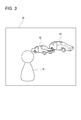
図3は、カメラ背面に設けられた液晶表示部29の表示画面例を示す図である。人物画像41に焦点が合っており、その向こう側に2台の自動車画像42,43が映っている。
スルー画像で表示された図3の立体画像をユーザが見ても、焦点がどの画像に合っているのか明確に認識できない場合がある。この例では、実際に自動車画像42に焦点が合っており、ユーザは人物画像41に焦点を合わせたいと思っているとする。
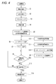
図4は、図2のCPU26がユーザからの指示入力により実行する視差調整処理手順を示すフローチャートである。この処理が開始されると、先ず、ステップS1で、画像(固体撮像素子23Lで撮像された左眼用二次元画像と、固体撮像素子23Rで撮像された右眼用二次元画像)の夫々の特徴点が抽出される。
次のステップS2で、左右画像の特徴点間の対応点が算出される。ステップS1では、左眼用二次元画像中の特徴点と、右眼用二次元画像中の特徴点が抽出されるが、両方の画像の特徴点抽出アルゴリズムが同じであるため、両画像で同じ特徴点が抽出されることになる。つまり、両画像における同じ特徴点間の対応が、このステップS2で算出される。対応する特徴点間の距離が、視差量となる。
次のステップS3では、クラスタリングが行われる。即ち、ステップS1で抽出され、ステップS2で対応付けがされた特徴点のクラスタリングが行われ、図3で言えば、画像41に属する特徴点の集合,画像42に属する特徴点の集合,画像43に属する特徴点の集合のクラスタリングが行われ、以後、特徴点は被写体画像毎に管理される。
次のステップS4では、カメラから各特徴点(の集合)までの距離が計算され、ステップS5で、カメラ10からの距離で、視差ゼロ(以下、クロスポイントという。)となる距離が算出されると共に、立体視可能範囲が算出される。
次のステップS6で、CPU26は、撮像されている被写体(シーン)を光軸に対して上方から見た擬似俯瞰図(以下、レーダーチャートとも言う。図5で説明する。)を、液晶表示29に扇領域で表示する。このとき、例えば、表示画像中の特定の被写体の画像に対して例えば丸枠、四角枠、三角枠などを特定の被写体毎に重ねて表示し、レーダーチャート内では被写体画像の替わりにこれら丸枠,四角枠,三角枠等のアイコン(色付きで区別しても良い)で表示する(ステップS7)。このように、CPU26は、液晶表示部29の一部表示領域に、立体画像撮影時の光軸に対し上方から被写体を見たレーダーチャート50で表示させる表示制御部として機能する。
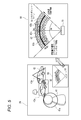
図5の左図は、図3の被写体画像中の特定被写体画像41,42,43に、夫々、丸枠41a、四角枠42a、三角枠43aを重ねて表示した図である。左眼用二次元画像と右眼用二次元画像とが重なった状態で表示されている。実際には、左眼用二次元画像と右眼用二次元画像とが1フレーム毎に交互に表示され、これがレンチキュラレンズシートを通して表示画面を見る人の眼に入るため、立体画像として認識される。そして、画面の空き領域例えば右下領域に小さなウインドウを開き、このウインドウ内に上記のレーダーチャート50を表示する。
図5の右図は、レーダーチャート50の拡大図である。図中の円弧状の太線51は、視差量ゼロを表すラインを示している。視差ゼロを表すライン51を、以下、クロスポイントラインということにする。
視差量ゼロのクロスポイントでは、左眼用二次元画像と右眼用二次元画像との視差がなく、一致している。図示の例では、画像42に合焦しているため、画像42の左眼用二次元画像上の特徴点と右眼用二次元画像上の特徴点間にズレはなく、一致している。このため、レーダーチャート50上では、画像42を示すアイコン(この例では四角枠)42bがクロスポイントライン51上に来ている。
これに対し、レーダーチャート50上で画像41を示すアイコン(丸枠)41bはクロスポイントライン51より手前にあり、画像43を示すアイコン(三角枠)43bはクロスポイントライン51より向こう側にある。図中の網掛けした円弧領域52は、立体視することができる範囲を示している。また、中央線上に、カメラが計算して求めた概略距離を示している。
図4に戻り、ステップS7の次のステップS8で、視差調整操作がされたか否かを判定する。視差調整は、例えば左右の画像を近づけたり遠ざけたりする操作(例えば視差調整を指定し、操作用十字キー等で行う。)で行う。
この視差調整操作が行われた場合には、ステップS8からステップS9に進み、視差調整操作後のカメラ10からクロスポイントまでの距離を再計算する。そして次のステップS10で、クロスポイントライン51の表示を更新指示する。
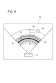
このクロスポイントライン51の更新指示と共に、立体視可能範囲52を再計算し(ステップS11)、この立体視可能範囲の表示を更新指示し(ステップS12)、ステップS6に戻って更新したレーダーチャート50を再表示する。再表示されたレーダーチャート50の拡大図を図6に示す。クロスポイントラインは人物画像のアイコン41bの位置に合うように移動(矢印54)している。
この様に、本実施形態では、視差調整を行うことで、視差量ゼロとなるカメラからの距離が変化するため、それに併せてレーダーチャート50上のクロスポイントライン51の表示位置を移動させる。もしユーザが、人物画像41に合焦させたいと思えば、レーダーチャート50上で、クロスポイントライン51が人物画像41に対応するアイコン41bに重なる位置となるように視差調整を行えば良い。
ステップS8の判定の結果、視差調整操作が無い場合にはステップS8からステップS13に進み、視差調整の終了操作があるか否かを判定する。この終了操作が無い場合にはステップS8に戻り、終了操作がある場合には視差調整を終了し(ステップS14)、この処理を終了する。
図7は、視差調整終了後の画面表示例を示す図である。図5の左図では、人物画像41の左右の画像はズレていたが、図7では、人物画像41で視差ゼロとなるため、左眼用二次元画像中の人物画像41と右眼用二次元画像中の人物画像41とは一致することになる。
この様に、本実施形態によれば、レーダーチャート50の表示により、カメラから各被写体までの距離を視認することができ、クロスポイントと各被写体の前後関係を視認でき、画面から飛び出して表示させる被写体や引っ込ませて表示させる被写体を明確に視認しすることが可能となる。更に、立体視可能な領域52を表示することで、複数の被写体の相対関係を確認しながら調整することが可能となる。
なお、上述した実施形態では、特定の被写体毎のアイコンを表示したが、特徴点を何かしらの図形でレーダーチャート上に表示しても良く、また、レーダーチャートに被写体画像対応のオブジェクト(人の形状や建物,車の形状)を表示させることでも良い。
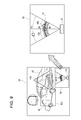
図8は、本発明の別実施形態に係る視差調整処理手順を示すフローチャートである。カメラ10に搭載されている撮影レンズが望遠(ズーム)レンズ機能を持っている場合、ズーム操作がされると、図9に示す様に、立体視可能な領域が変わり、遠方の被写体が立体視可能となる。そこで、本実施形態では、ズーム操作で画角が変わるか否かを判定する処理を入れている。
この図8の実施形態では、図4のフローチャートのステップS8とステップS13との間に「ズーム操作有りか否か」の判定処理ステップS16を入れた点が図4の実施形態と異なり、その他の処理ステップは図4と同じであるため、同じ処理ステップには同じステップ番号を付してその説明は省略する。
本実施形態では、ステップS8の視差調整操作有りの判定処理で視差調整操作無しと判定された場合には、次のステップS16で、ズーム操作有りか否かを判定する。そして、ズーム操作無しの場合にステップS13に進んで終了操作有りの判定処理に進む。
ステップS16の判定処理の結果、ズーム操作有りと判定された場合にはステップS1に戻り、視差調整処理手順を最初からやり直す。この結果、図9に示す様に、ズーム量に応じたレーダーチャート50が表示され、ユーザはズーム量に応じた視差調整を行うことが可能となる。
図10は、本発明の更に別実施形態に係る視差調整処理手順を示すフローチャートである。デジタルカメラでは、ユーザがカメラ背面の表示画像を見てフォーカスが合っている否かを確認するとき、例えば特開2006―222979号公報に記載されている様に、フォーカスさせたい画像部分を拡大表示し、ユーザにピント合わせをやり直しさせる機能を持つものがある。
この様なフォーカス確認機能を持つデジタルカメラに適用するのが、図10の実施形態である。図10の処理手順は図4の処理手順と殆ど同じであり、図4の処理ステップS7と処理ステップS8の間にフォーカス確認処理ステップS20を設けた点だけが異なり、他の処理ステップは図4と同じであるため、同一ステップに同一ステップ番号を付してその説明は省略する。
カメラ背面の液晶表示部29に撮像画像を表示すると共に、ステップS6でレーダーチャート50を表示し、ステップS7で特定被写体画像対応のアイコンを表示した後、フォーカス確認処理ステップS20に進む。
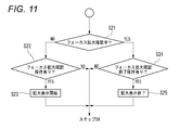
このステップS20に入ると、図11に示す様に、先ず、ステップS21で、フォーカス領域を拡大してユーザがフォーカスを確認中であるか否かを判定する。フォーカス領域を拡大していない場合(ステップS21の判定結果がNOの場合)には、ステップS22に進み、フォーカス領域の拡大確認指示の操作が有るか否かを判定する。この判定結果が肯定の場合にはステップS23でフォーカス領域の拡大表示を開始し、図10のステップS8に進む。
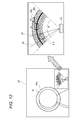
図12の左図は、フォーカス領域を拡大した図を例示する図である。この例では、人物画像41が拡大表示され、ユーザは画像41の拡大図を見て、ピントが合っているか否かを確認できる。このとき、図12の右図に示す様に、レーダーチャート50上で、左図で拡大している範囲を示す線56,57を例えば赤線等で他と区別化表示するのが良い。こうすると、ユーザはレーダーチャート50上で拡大表示している画角を確認することが可能となる。
ステップS21の判定の結果、フォーカス領域を拡大して確認している場合(判定結果が肯定)には、ステップS24に進み、今度はフォーカス領域の拡大確認の終了操作が有るか否かを判定する。この判定結果が肯定の場合にはステップS25に進み、拡大表示を終了し、ステップS8に進む。ステップS22,S24の判定結果が否定の場合にもステップS8に進む。
なお、上述した実施形態では、2眼式の立体画像撮像装置で撮影レンズ21L,21Rの光軸22L,22Rを固定式とし、各々の撮像画像を水平方向にずらす画素数を制御することで視差量を調整し立体感を出したが、各撮影レンズの光軸22L,22Rの向きを調整可能して輻輳角を制御する構成としても良い。また、画像処理で2枚の撮像画像の水平方向のズラシ量を変えて立体感を変えたが、これは、スルー画像だけでなく、既に撮影済みの立体画像の視差量ゼロの位置を変更する場合にも適用できる。
また、図8と図10の実施形態を別々に説明したが、これらの実施形態を両方実施することも可能であることはいうまでもない。
以上述べた実施形態の画像表示装置は、視点の異なる複数の画像を取得する立体画像取得部と、前記立体画像取得部により取得された前記複数の画像を表示する表示部と、前記複数の画像のいずれかにおいて、特定の被写体を選択する被写体選択部と、前記複数の画像の中の第1の視点画像と第2の視点画像との視差量がゼロとなるラインと、前記視差量がゼロとなるラインと前記特定の被写体の位置との立体画像撮影時の光軸方向における前後関係とを、前記表示部の一部表示領域に、前記立体画像撮影時の光軸に対し上方から前記被写体を見た擬似俯瞰図で表示する表示制御部とを備えることを特徴とする。
また、実施形態の画像表示装置の前記表示制御部は、前記擬似俯瞰図上で、前記特定の被写体の画像位置をアイコンで表示することを特徴とする。
また、実施形態の画像表示装置の前記表示制御部は、前記擬似俯瞰図に、前記視差量がゼロとなるラインの前後に立体視可能な領域を表示することを特徴とする。
また、実施形態の画像表示装置の前記表示制御部は、前記第1の視点画像と第2の視点画像との視差調整が行われ、前記視差量がゼロとなるラインが変更された場合に、前記擬似俯瞰図の表示を更新することを特徴とする。
また、実施形態の画像表示装置の前記表示制御部は、前記被写体のいずれかにピントを合わせるフォーカスエリア内の拡大画像の確認操作がされた場合に、該拡大画像に対応して前記擬似俯瞰図の表示を更新することを特徴とする。
また、実施形態の画像表示装置の表示制御部は、前記擬似俯瞰図に、距離表示をすることを特徴とする。
また、実施形態の画像表示装置の視差調整表示方法は、視点の異なる複数の画像を取得する立体画像取得部と、前記立体画像取得部により取得された前記複数の画像を表示する表示部と、前記複数の画像のいずれかにおいて特定の被写体を選択する被写体選択部とを備える画像表示装置の視差調整表示方法であって、
前記複数の画像の中の第1の視点画像と第2の視点画像との視差量がゼロとなるラインと、前記視差量がゼロとなるラインと前記特定の被写体の位置との立体画像撮影時の光軸方向における前後関係とを、前記表示部の一部表示領域に、前記立体画像撮影時の光軸に対し上方から前記被写体を見た擬似俯瞰図で表示することを特徴とする。
前記複数の画像の中の第1の視点画像と第2の視点画像との視差量がゼロとなるラインと、前記視差量がゼロとなるラインと前記特定の被写体の位置との立体画像撮影時の光軸方向における前後関係とを、前記表示部の一部表示領域に、前記立体画像撮影時の光軸に対し上方から前記被写体を見た擬似俯瞰図で表示することを特徴とする。
また、実施形態の画像撮像装置は、視点の異なる複数の画像を取得する立体画像取得部と、前記立体画像取得部により取得された前記複数の画像を表示する表示部と、前記複数の画像のいずれかにおいて特定の被写体を選択する被写体選択部と、前記複数の画像の中の第1の視点画像と第2の視点画像との視差量がゼロとなるラインと、前記視差量がゼロとなるラインと前記特定の被写体の位置との立体画像撮影時の光軸方向における前後関係とを、前記表示部の一部表示領域に、前記立体画像撮影時の光軸に対し上方から前記被写体を見た擬似俯瞰図で表示する表示制御部とを備えることを特徴とする。
また、実施形態の画像撮像装置は、ズームレンズを備え、前記表示制御部は、前記ズームレンズのズーム操作を検出したとき、前記ズームレンズのズーム量に応じて前記擬似俯瞰図の表示を更新することを特徴とする。
以上述べた実施形態によれば、擬似俯瞰図(レーダーチャート)を表示し視差調整によって視差量ゼロの位置を変更するため、視差を調整したときの影響を容易に知ることができ、視差調整がし易くなる。
本発明に係る視差調整表示方法によれば、視差を調整したときどのように立体画像の立体感に影響するかを直感的に知ることができるため、ステレオカメラの様な画像撮像装置や、画像撮像装置に内蔵される画像表示装置や、立体画像データをパソコンなどに取り込んで処理するときの画像表示装置等に適用すると有用である。画像表示装置でも、画像データのヘッダ情報から立体画像データであることを示す情報を取得でき、上記の立体画像撮像装置と同様の処理が可能となる。
本発明を詳細にまた特定の実施態様を参照して説明したが、本発明の精神と範囲を逸脱することなく様々な変更や修正を加えることができることは当業者にとって明らかである。
本出願は、2011年9月30日出願の日本特許出願(特願2011-218535)に基づくものであり、その内容はここに参照として取り込まれる。
本出願は、2011年9月30日出願の日本特許出願(特願2011-218535)に基づくものであり、その内容はここに参照として取り込まれる。
10 立体画像撮像装置(立体カメラ)
15 シャッタボタン
21R,21L 撮影レンズ
23L,23R 撮像素子(イメージセンサ)
26 システム制御部(CPU)
28 画像処理部(DSP)
29 表示部
41,42,43 特定被写体の画像
41a,42a,43a 特定被写体に対応する枠形状
41b,42b,43b 特定被写体に対応したアイコン
50 擬似俯瞰図(レーダーチャート)
51 視差ゼロのライン(クロスポイントライン)
52 立体視可能領域
15 シャッタボタン
21R,21L 撮影レンズ
23L,23R 撮像素子(イメージセンサ)
26 システム制御部(CPU)
28 画像処理部(DSP)
29 表示部
41,42,43 特定被写体の画像
41a,42a,43a 特定被写体に対応する枠形状
41b,42b,43b 特定被写体に対応したアイコン
50 擬似俯瞰図(レーダーチャート)
51 視差ゼロのライン(クロスポイントライン)
52 立体視可能領域
Claims (9)
- 視点の異なる複数の画像を取得する立体画像取得部と、
前記立体画像取得部により取得された前記複数の画像を表示する表示部と、
前記複数の画像のいずれかにおいて、特定の被写体を選択する被写体選択部と、
前記複数の画像の中の第1の視点画像と第2の視点画像との視差量がゼロとなるラインと、前記視差量がゼロとなるラインと前記特定の被写体の位置との立体画像撮影時の光軸方向における前後関係とを、前記表示部の一部表示領域に、前記立体画像撮影時の光軸に対し上方から前記被写体を見た擬似俯瞰図で表示する表示制御部と
を備える画像表示装置。 - 請求項1に記載の画像表示装置であって、前記表示制御部は、前記擬似俯瞰図上で、前記特定の被写体の画像位置をアイコンで表示する画像表示装置。
- 請求項1又は請求項2に記載の画像表示装置であって、前記表示制御部は、前記擬似俯瞰図に、前記視差量がゼロとなるラインの前後に立体視可能な領域を表示する画像表示装置。
- 請求項乃至請求項3のいずれか1項に記載の画像表示装置であって、前記表示制御部は、前記第1の視点画像と第2の視点画像との視差調整が行われ、前記視差量がゼロとなるラインが変更された場合に、前記擬似俯瞰図の表示を更新する画像表示装置。
- 請求項1乃至請求項4のいずれか1項に記載の画像表示装置であって、前記表示制御部は、前記被写体のいずれかにピントを合わせるフォーカスエリア内の拡大画像の確認操作がされた場合に、該拡大画像に対応して前記擬似俯瞰図の表示を更新する画像表示装置。
- 請求項1乃至請求項5のいずれか1項に記載の画像表示装置であって、前記表示制御部は、前記擬似俯瞰図に距離表示をする画像表示装置。
- 視点の異なる複数の画像を取得する立体画像取得部と、前記立体画像取得部により取得された前記複数の画像を表示する表示部と、前記複数の画像のいずれかにおいて特定の被写体を選択する被写体選択部とを備える画像表示装置の視差調整表示方法であって、
前記複数の画像の中の第1の視点画像と第2の視点画像との視差量がゼロとなるラインと、前記視差量がゼロとなるラインと前記特定の被写体の位置との立体画像撮影時の光軸方向における前後関係とを、前記表示部の一部表示領域に、前記立体画像撮影時の光軸に対し上方から前記被写体を見た擬似俯瞰図で表示する画像表示装置の視差調整表示方法。 - 請求項1乃至請求項6のいずれか1項に記載の画像表示装置を備える画像撮像装置。
- 請求項8に記載の画像撮像装置であって、ズームレンズを備え、前記表示制御部は、前記ズームレンズのズーム操作を検出したとき、前記ズームレンズのズーム量に応じて前記擬似俯瞰図の表示を更新する画像撮像装置。
Priority Applications (2)
| Application Number | Priority Date | Filing Date | Title |
|---|---|---|---|
| JP2013535992A JP5586788B2 (ja) | 2011-09-30 | 2012-06-26 | 画像表示装置及び画像撮像装置 |
| US14/228,665 US9325975B2 (en) | 2011-09-30 | 2014-03-28 | Image display apparatus, parallax adjustment display method thereof, and image capturing apparatus |
Applications Claiming Priority (2)
| Application Number | Priority Date | Filing Date | Title |
|---|---|---|---|
| JP2011-218535 | 2011-09-30 | ||
| JP2011218535 | 2011-09-30 |
Related Child Applications (1)
| Application Number | Title | Priority Date | Filing Date |
|---|---|---|---|
| US14/228,665 Continuation US9325975B2 (en) | 2011-09-30 | 2014-03-28 | Image display apparatus, parallax adjustment display method thereof, and image capturing apparatus |
Publications (1)
| Publication Number | Publication Date |
|---|---|
| WO2013046833A1 true WO2013046833A1 (ja) | 2013-04-04 |
Family
ID=47994893
Family Applications (1)
| Application Number | Title | Priority Date | Filing Date |
|---|---|---|---|
| PCT/JP2012/066254 Ceased WO2013046833A1 (ja) | 2011-09-30 | 2012-06-26 | 画像表示装置及びその視差調整表示方法並びに画像撮像装置 |
Country Status (3)
| Country | Link |
|---|---|
| US (1) | US9325975B2 (ja) |
| JP (1) | JP5586788B2 (ja) |
| WO (1) | WO2013046833A1 (ja) |
Cited By (1)
| Publication number | Priority date | Publication date | Assignee | Title |
|---|---|---|---|---|
| CN105659580A (zh) * | 2014-09-30 | 2016-06-08 | 华为技术有限公司 | 一种自动对焦方法、装置及电子设备 |
Families Citing this family (2)
| Publication number | Priority date | Publication date | Assignee | Title |
|---|---|---|---|---|
| US10070048B2 (en) * | 2013-03-26 | 2018-09-04 | Htc Corporation | Panorama photographing method, panorama displaying method, and image capturing method |
| USD795925S1 (en) * | 2014-04-16 | 2017-08-29 | Hitachi, Ltd. | Display screen or portion thereof with icon |
Citations (6)
| Publication number | Priority date | Publication date | Assignee | Title |
|---|---|---|---|---|
| JPH07167633A (ja) * | 1993-08-26 | 1995-07-04 | Matsushita Electric Ind Co Ltd | 立体画像撮像及び表示装置 |
| JP2004363680A (ja) * | 2003-06-02 | 2004-12-24 | Pioneer Electronic Corp | 表示装置及び方法 |
| JP2010177741A (ja) * | 2009-01-27 | 2010-08-12 | Olympus Corp | 撮像装置 |
| JP2011010128A (ja) * | 2009-06-26 | 2011-01-13 | Canon Inc | 再生装置、撮像装置、及びその制御方法 |
| JP2011013993A (ja) * | 2009-07-03 | 2011-01-20 | Fujifilm Corp | 画像表示装置および方法並びにプログラム |
| JP2011015721A (ja) * | 2009-07-07 | 2011-01-27 | Fa System Engineering Kk | 立体映像表示装置の立体スケール像形成装置 |
Family Cites Families (10)
| Publication number | Priority date | Publication date | Assignee | Title |
|---|---|---|---|---|
| EP0641132B1 (en) | 1993-08-26 | 1999-04-14 | Matsushita Electric Industrial Co., Ltd. | Stereoscopic image pickup apparatus |
| JP2001320733A (ja) | 2000-05-12 | 2001-11-16 | Sony Corp | 立体画像表示システム、立体画像表示装置、立体画像表示方法及び記憶媒体 |
| JP3857988B2 (ja) | 2002-03-27 | 2006-12-13 | 三洋電機株式会社 | 立体画像処理方法および装置 |
| US8369607B2 (en) | 2002-03-27 | 2013-02-05 | Sanyo Electric Co., Ltd. | Method and apparatus for processing three-dimensional images |
| JP4228646B2 (ja) * | 2002-10-02 | 2009-02-25 | 株式会社セガ | 立体視画像生成方法および立体視画像生成装置 |
| AU2003221143A1 (en) | 2003-03-20 | 2004-10-11 | Seijiro Tomita | Stereoscopic video photographing/displaying system |
| JP4315117B2 (ja) * | 2004-04-02 | 2009-08-19 | 株式会社デンソー | 車両周辺監視システム |
| JP2006107213A (ja) | 2004-10-06 | 2006-04-20 | Canon Inc | 立体画像印刷システム |
| JP5346266B2 (ja) | 2009-09-30 | 2013-11-20 | 富士フイルム株式会社 | 画像処理装置、カメラ及び画像処理方法 |
| US20120162384A1 (en) * | 2010-12-22 | 2012-06-28 | Vesely Michael A | Three-Dimensional Collaboration |
-
2012
- 2012-06-26 WO PCT/JP2012/066254 patent/WO2013046833A1/ja not_active Ceased
- 2012-06-26 JP JP2013535992A patent/JP5586788B2/ja not_active Expired - Fee Related
-
2014
- 2014-03-28 US US14/228,665 patent/US9325975B2/en not_active Expired - Fee Related
Patent Citations (6)
| Publication number | Priority date | Publication date | Assignee | Title |
|---|---|---|---|---|
| JPH07167633A (ja) * | 1993-08-26 | 1995-07-04 | Matsushita Electric Ind Co Ltd | 立体画像撮像及び表示装置 |
| JP2004363680A (ja) * | 2003-06-02 | 2004-12-24 | Pioneer Electronic Corp | 表示装置及び方法 |
| JP2010177741A (ja) * | 2009-01-27 | 2010-08-12 | Olympus Corp | 撮像装置 |
| JP2011010128A (ja) * | 2009-06-26 | 2011-01-13 | Canon Inc | 再生装置、撮像装置、及びその制御方法 |
| JP2011013993A (ja) * | 2009-07-03 | 2011-01-20 | Fujifilm Corp | 画像表示装置および方法並びにプログラム |
| JP2011015721A (ja) * | 2009-07-07 | 2011-01-27 | Fa System Engineering Kk | 立体映像表示装置の立体スケール像形成装置 |
Cited By (5)
| Publication number | Priority date | Publication date | Assignee | Title |
|---|---|---|---|---|
| CN105659580A (zh) * | 2014-09-30 | 2016-06-08 | 华为技术有限公司 | 一种自动对焦方法、装置及电子设备 |
| CN105659580B (zh) * | 2014-09-30 | 2018-09-07 | 华为技术有限公司 | 一种自动对焦方法、装置及电子设备 |
| US10129455B2 (en) | 2014-09-30 | 2018-11-13 | Huawei Technologies Co., Ltd. | Auto-focus method and apparatus and electronic device |
| CN108924428A (zh) * | 2014-09-30 | 2018-11-30 | 华为技术有限公司 | 一种自动对焦方法、装置及电子设备 |
| US10455141B2 (en) | 2014-09-30 | 2019-10-22 | Huawei Technologies Co., Ltd. | Auto-focus method and apparatus and electronic device |
Also Published As
| Publication number | Publication date |
|---|---|
| US20140210953A1 (en) | 2014-07-31 |
| JPWO2013046833A1 (ja) | 2015-03-26 |
| US9325975B2 (en) | 2016-04-26 |
| JP5586788B2 (ja) | 2014-09-10 |
Similar Documents
| Publication | Publication Date | Title |
|---|---|---|
| JP5640155B2 (ja) | 立体画像撮像装置及びその合焦状態確認用画像表示方法 | |
| JP5425554B2 (ja) | 立体撮像装置及び立体撮像方法 | |
| JP5449536B2 (ja) | 立体画像再生装置及び方法、立体撮像装置、立体ディスプレイ装置 | |
| CN102172031B (zh) | 三维显示设备和三维显示方法 | |
| JP5449535B2 (ja) | 立体撮像装置及びその制御方法 | |
| JP2001142166A (ja) | 3dカメラ | |
| WO2011136191A1 (ja) | 立体画像再生装置及び方法、立体撮像装置、立体ディスプレイ装置 | |
| JP2011077900A (ja) | 画像処理装置、カメラ及び画像処理方法 | |
| JP5647740B2 (ja) | 視差調節装置及び方法、撮影装置、再生表示装置 | |
| JP2012186612A (ja) | 撮像装置 | |
| JP5449551B2 (ja) | 画像出力装置、方法およびプログラム | |
| CN102986232A (zh) | 图像处理装置、方法及程序 | |
| JP5580486B2 (ja) | 画像出力装置、方法およびプログラム | |
| JP2010147940A (ja) | 立体画像処理装置および立体画像処理方法 | |
| JP5586788B2 (ja) | 画像表示装置及び画像撮像装置 | |
| JP5891645B2 (ja) | 撮像装置およびプログラム | |
| JP2015094831A (ja) | 立体撮像装置およびその制御方法、制御プログラム | |
| JP2014154907A (ja) | 立体撮像装置 | |
| JP5571257B2 (ja) | 画像処理装置、方法およびプログラム | |
| WO2006016534A1 (ja) | 画像撮影装置 | |
| JP2010226320A (ja) | 撮像装置 | |
| JP2012044319A (ja) | 画像処理装置、画像処理方法及び立体撮像装置 | |
| JP2013228478A (ja) | 撮像装置、その制御方法、および制御プログラム | |
| KR20090015577A (ko) | 스테레오 카메라에서 촬영상태 정보 제공 방법 및 장치 |
Legal Events
| Date | Code | Title | Description |
|---|---|---|---|
| 121 | Ep: the epo has been informed by wipo that ep was designated in this application |
Ref document number: 12835961 Country of ref document: EP Kind code of ref document: A1 |
|
| ENP | Entry into the national phase |
Ref document number: 2013535992 Country of ref document: JP Kind code of ref document: A |
|
| NENP | Non-entry into the national phase |
Ref country code: DE |
|
| 122 | Ep: pct application non-entry in european phase |
Ref document number: 12835961 Country of ref document: EP Kind code of ref document: A1 |