WO2013046793A1 - エアベアリングユニット - Google Patents
エアベアリングユニット Download PDFInfo
- Publication number
- WO2013046793A1 WO2013046793A1 PCT/JP2012/062517 JP2012062517W WO2013046793A1 WO 2013046793 A1 WO2013046793 A1 WO 2013046793A1 JP 2012062517 W JP2012062517 W JP 2012062517W WO 2013046793 A1 WO2013046793 A1 WO 2013046793A1
- Authority
- WO
- WIPO (PCT)
- Prior art keywords
- air
- bearing gap
- radial bearing
- thrust bearing
- thrust
- Prior art date
- Legal status (The legal status is an assumption and is not a legal conclusion. Google has not performed a legal analysis and makes no representation as to the accuracy of the status listed.)
- Ceased
Links
Images



Classifications
-
- F—MECHANICAL ENGINEERING; LIGHTING; HEATING; WEAPONS; BLASTING
- F16—ENGINEERING ELEMENTS AND UNITS; GENERAL MEASURES FOR PRODUCING AND MAINTAINING EFFECTIVE FUNCTIONING OF MACHINES OR INSTALLATIONS; THERMAL INSULATION IN GENERAL
- F16C—SHAFTS; FLEXIBLE SHAFTS; ELEMENTS OR CRANKSHAFT MECHANISMS; ROTARY BODIES OTHER THAN GEARING ELEMENTS; BEARINGS
- F16C32/00—Bearings not otherwise provided for
- F16C32/06—Bearings not otherwise provided for with moving member supported by a fluid cushion formed, at least to a large extent, otherwise than by movement of the shaft, e.g. hydrostatic air-cushion bearings
- F16C32/0603—Bearings not otherwise provided for with moving member supported by a fluid cushion formed, at least to a large extent, otherwise than by movement of the shaft, e.g. hydrostatic air-cushion bearings supported by a gas cushion, e.g. an air cushion
- F16C32/0614—Bearings not otherwise provided for with moving member supported by a fluid cushion formed, at least to a large extent, otherwise than by movement of the shaft, e.g. hydrostatic air-cushion bearings supported by a gas cushion, e.g. an air cushion the gas being supplied under pressure, e.g. aerostatic bearings
Definitions
- the present invention relates to a structure of an air bearing unit that supports parts such as a pulley that rotates at a high speed with a simple structure and more stably in a non-contact manner.
- Patent Document 1 describes an air bearing unit (static pressure air bearing device) that supports a rotating shaft in a non-contact manner.
- the inner periphery of a cylindrical housing into which a shaft (rotating shaft) is inserted has a porous bearing that receives the thrust load and radial load of the shaft on individual bearing surfaces (thrust bearing surface, radial bearing surface).
- An air bearing (hydrostatic air bearing) of a quality-drawn type (a porous body such as porous graphite) is provided.
- the radial bearing surface is opposed to the outer peripheral surface of the shaft and a radial bearing gap is formed between the radial bearing surface and the thrust bearing surface is opposed to the flange formed on the outer periphery of the shaft.
- a thrust bearing gap is formed between the flange and the flange.
- an exhaust groove is formed in the circumferential direction on the opposite side of the thrust bearing surface (opposite to the flange) across the radial bearing surface of the air bearing, and the outer peripheral surface of the shaft
- the exhaust groove is formed in the circumferential direction at a position near the thrust bearing surface of the air bearing.
- the air supplied to the air bearing is ejected from the thrust bearing surface and the radial bearing surface of the air bearing.
- the air ejected from the thrust bearing surface flows in the thrust bearing gap toward the outer periphery of the flange, and is discharged to the outside through the thrust bearing gap.
- the air ejected from the radial bearing surface flows in the radial bearing gap toward the exhaust groove near the thrust bearing surface and the exhaust groove on the opposite side of the thrust bearing surface, and flows into these exhaust grooves. .
- the present invention has been made in view of the above circumstances, and an object of the present invention is to provide a compact air bearing unit structure that supports a component that rotates at a high speed with a simple structure and more stably in a non-contact manner. .
- a fluid is supplied from the porous layer to the radial bearing gap to form a fluid film in the radial bearing gap, and the fluid is exhausted from the radial bearing gap to the thrust bearing gap. Using this exhausted fluid, a fluid film is also formed in the thrust bearing gap.
- the present invention is an air bearing unit that supports a rotating body rotating in a direction around an axis center in a non-contact manner by a fluid film interposed in a radial bearing gap and a first thrust bearing gap, Forming the radial bearing gap with the rotating body, the first surface surrounding the shaft center, and the first thrust bearing gap connected to one end side of the radial bearing gap with the rotating body A back metal having a second surface adjacent to the first surface, formed between, A porous layer that is formed on the first surface and that supplies the fluid that forms the fluid film in the radial bearing gap to the radial bearing gap;
- the fluid is The fluid flows in the radial bearing gap toward the first thrust bearing gap, and is exhausted from the radial bearing gap to the first thrust bearing gap, thereby forming the fluid film in the first thrust bearing gap.
- the compressed gas exhausted from the radial bearing gap is exhausted after being supplied to the thrust bearing gap, so that the groove for exhausting the compressed gas from the radial bearing gap or the thrust bearing gap There is no need to separately provide a thrust bearing surface for ejecting compressed air. Therefore, it is possible to simplify the structure of the air bearing unit that holds the components rotating at high speed in a non-contact manner.
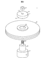
- FIG. 1A and 1B are an external view and a side view of an air bearing unit 1 with a pulley according to an embodiment of the present invention.
- FIG. 2 is a part development view of the air bearing unit 1 with pulley according to the embodiment of the present invention.
- 3A is a front view of the pulley 20, and FIG. 3B is a cross-sectional view taken along the line AA in FIG. 3A.
- 4A, 4 ⁇ / b> B, and 4 ⁇ / b> C are an external view, a cross-sectional view, and a bottom view of the air shaft 10, and
- FIG. 4D is an enlarged partial cross-sectional view of the radial bearing portion 104.
- 5A is a front view of the thrust plate 11
- FIG. 5B is a cross-sectional view taken along the line BB of FIG. 5A.
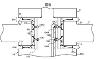
- FIG. 6 is a diagram schematically showing the support state of the pulley 20 during the supply of air to the air shaft 10.
- an air bearing unit 1 with a pulley that rotatably supports a pulley 20 that feeds a wire such as an optical fiber in a non-contact manner is taken as an example.
- FIG. 1 (A) and 1 (B) are an external view and a side view of an air bearing unit 1 with pulley according to the present embodiment
- FIG. 2 is an exploded view of components of the air bearing unit 1 with pulley.
- the air bearing unit with pulley 1 is inserted into a pulley 20 to be supported and an air shaft insertion hole 23 of the pulley 20 described later, and the pulley 20 can be rotated in a non-contact manner.
- the air shaft 10 is supported, the thrust plate 11 prevents the pulley 20 from falling off the air shaft 10, and the nut 12 that fixes the thrust plate 11 to the air shaft 10.
- the pulley 20 is assembled to the air shaft 10 by inserting the radial bearing portion 104 of the air shaft 10 into the air shaft insertion hole 23 and tightening the nut 20 via the thrust plate 11 with the nut 12.
- FIG. 3A is a front view of the pulley 20, and FIG. 3B is a cross-sectional view taken along the line AA in FIG. 3A.
- the pulley 20 has a disk shape, and a V-groove 26 on which a wire is applied is formed in the outer circumferential surface 29 in the circumferential direction.
- the pulley 20 is formed with an air shaft insertion hole 23 penetrating from one surface 21 to the other surface 22 at a position where the central axis O1 passes.
- a radial bearing portion 104 of the air shaft 10 described later is slidably inserted into the air shaft insertion hole 23.
- Bosses 24 and 25 surrounding the air shaft insertion hole 23 are formed on both surfaces 21 and 22 of the pulley 20, respectively. End surfaces 241 and 251 of the bosses 24 and 25 are finished flat.
- the end surface 251 of one boss 25 faces a step surface 1034 of the air shaft 10 described later, and the end surface 241 of the other boss 24 is described later. It faces one surface 111 of the thrust plate 11.
- FIG. 4A, 4B, and 4C are an external view, a cross-sectional view, and a bottom view of the air shaft 10, and FIG. 4D is an enlarged partial cross-sectional view of the radial bearing portion 104.
- the air shaft 10 includes a stepped columnar back metal 101 and a porous sintered layer 102 formed on the outer peripheral surface 1042 of the middle step portion (radial bearing portion) 104 of the back metal 101. I have.
- the back metal 101 includes a base portion 103 having substantially the same diameter as the outer diameters of the bosses 24 and 25 of the pulley 20, a radial bearing portion 104 having a smaller diameter than the base portion 103, and a rod portion 105 having a smaller diameter than the radial bearing portion 104. And.
- a plurality of screw holes 1032 for fixing the air bearing unit with pulley 1 to a base such as a stone surface plate are formed on one end face (bottom face) 1031 of the base portion 103.
- the base portion 103 has an air passage 106 that passes through the inside of the base portion 103 from the bottom surface 1031 to the inside of the radial bearing portion 104, and an air supply port 107 that is connected to the air passage 106 from the outer peripheral surface 1033. Is formed.
- a screw portion 1071 for connecting an air supply pipe (not shown) of the pump is formed in the opening portion of the air supply port 107.
- the opening 1061 of the air passage 106 is closed by a plug (not shown) so that the compressed air supplied from the air supply pipe of the pump to the air supply port 107 flows into the radial bearing 104 side.
- the radial bearing portion 104 is integrally formed with the other end surface (upper end surface) 1034 of the base portion 103, and a porous sintered layer 102 having air permeability is formed over the entire outer peripheral surface 1042 of the radial bearing portion 104.
- a porous sintered layer 102 having air permeability is formed over the entire outer peripheral surface 1042 of the radial bearing portion 104.
- Two grooves 1043 positioned on the back side of the porous sintered layer 102 are formed in the outer circumferential surface 1042 of the radial bearing portion 104 in the circumferential direction.
- a hole 1044 connected to the path 106 is formed.
- the number of grooves 1043 located on the back side of the porous sintered layer 102 is two, but the number of grooves 1043 on the back of the porous sintered layer 102 is the same as that of the porous sintered layer 102. What is necessary is just to determine according to the width h etc.
- the outer diameter R1 of the radial bearing portion 104 including the porous sintered layer 102 is designed to be smaller than the inner diameter r1 (see FIG. 3A) of the air shaft insertion hole 23 of the pulley 20 by a predetermined dimension. . Therefore, when the radial bearing portion 104 is inserted into the air shaft insertion hole 23 of the pulley 20, the inner peripheral surface 28 of the air shaft insertion hole 23 and the porous sintered layer 102 around the radial bearing portion 104 are formed.
- a radial bearing gap 60 is formed between the outer circumferential surface in the radial direction (that is, the radial bearing surface) 1021 (see FIG. 6).
- the two grooves 1043 are, for example, arranged away from the center position (h / 2 position) of the radial bearing portion 104 toward the base portion 103 side and the rod portion 105 side. It is preferable that it is arrange
- the height (distance between the stepped surfaces 1034 and 1041) h of the radial bearing portion 104 is more predetermined than the distance (the thickness of the pulley 20) t from the end surface 241 of the boss 24 of the pulley 20 to the end surface 251 of the boss 25.
- the size is designed to be larger. For this reason, after supplying air, a step formed by the difference in outer diameter between the end surface 251 of one boss 25 of the pulley 20 inserted into the radial bearing portion 104 and the radial bearing portion 104 and the base portion 103 and functions as a thrust bearing surface.
- a thrust bearing gap 61 a connected to the radial bearing gap 60 is formed between the surface (the upper end face of the base portion 103) 1034.
- a thrust bearing gap 61b connected to the radial bearing gap 60 is formed between one surface 111 of a later-described thrust plate 11 functioning as (see FIG. 6).
- the rod portion 105 is formed continuously with the upper end surface 1041 of the radial bearing portion 104, and is inserted into a shaft insertion hole 113 of a thrust plate 11 described later. Further, a screw portion 1051 that is screwed into the nut 12 is formed at the tip of the rod portion 105.
- FIG. 5 (A) is a front view of the thrust plate 11, and FIG. 5 (B) is a cross-sectional view taken along the line BB of FIG. 5 (A).
- the thrust plate 11 has a disk shape that is substantially the same diameter as the outer diameter of the base portion 103 of the air shaft 10, and extends from one surface 111 to the other surface 112 at a position through which the axis O ⁇ b> 1 passes.
- a shaft insertion hole 113 is formed therethrough. The rod portion 105 of the air shaft 10 is inserted into the shaft insertion hole 113. For this reason, the inner diameter r2 of the shaft insertion hole 113 is designed to be larger than the outer diameter R2 of the rod portion 105 of the air shaft 10.
- the air shaft 10 is inserted into the pulley 20 so that the radial bearing portion 104 of the air shaft 10 is positioned in the air shaft insertion hole 23 of the pulley 20, and then the shaft of the thrust plate 11 is inserted.
- the air shaft 10 into which the pulley 20 is inserted is further inserted into the thrust plate 11 so that the rod portion 105 of the air shaft 10 is positioned in the insertion hole 113.
- one surface 111 of the thrust plate 11 is caused by the outer diameter difference between the radial bearing portion 104 and the rod portion 105.
- a thrust bearing gap 61 a is formed between the upper end surface (thrust bearing surface) 1034 and a thrust bearing between the end surface 241 of the other boss 24 of the pulley 20 and one surface (thrust bearing surface) 111 of the thrust plate 11.
- a gap 61b is formed. The compressed air exhausted from the radial bearing gap 60 flows into the thrust bearing gaps 61a and 61b, and a high-pressure air film is formed. The thrust load is supported by the pressure of the air film.
- the height h of the radial bearing portion 104 is set so that the thickness s (see FIG. 6) of the thrust bearing gaps 61a and 61b on both sides of the pulley 20 is larger than the thickness of the radial bearing gap 60 to the extent that self-excited vibration does not occur. It is set to be larger.
- Thrust bearing gaps 61a and 61b having a thickness s that does not generate self-excited vibration are a slight movement that occurs in the pulley 20 in an unloaded state in the thrust direction, so that the pulley 20 has one thrust bearing surface 1034,
- the thrust bearing gaps 61a and 61b are wide enough that they do not suddenly be pushed back to the other thrust bearing surfaces 111 and 1034 even if they slightly approach the 111 side.
- the thickness s of the thrust bearing gaps 61a and 61b is about 22.5 to 37 ⁇ m.
- the height h of the radial bearing portion 104 is set, and the flow rate adjustment of the compressed air with a supply air pressure of 0.5 Mpa is performed in the range of the open flow rate of 520 NL / hr or less, thereby preventing the occurrence of self-excited vibration.
- FIG. 6 is a diagram schematically showing the support state of the pulley 20 during the supply of air to the air shaft 10.
- a pump air supply pipe (not shown) is connected to the air supply port 107 of the air shaft 10 and compressed air t from the pump is connected.
- the compressed air t is supplied to each groove 1043 located on the back side of the porous sintered layer 102 through the air passage 106 and the hole 1044 of the air shaft 10, and the porous sintered layer 102. From the outer circumferential surface 1021 in the radial direction. For this reason, a high-pressure air film is formed in the radial bearing gap 60, and the radial load is supported by the pressure. Thereby, the movement to the radial direction of the pulley 20 is restrained.
- the compressed air t in the radical bearing gap 60 passes along the radial outer peripheral surface (radial bearing surface) 1021 of the porous sintered layer 102 on one side (thrust bearing surface) 111 side of the thrust plate 11 and the base.
- a thrust bearing gap 61b between the end surface 241 of the other boss 24 of the pulley 20 and the thrust bearing surface 111 of the thrust plate 11, and the pulley. 20 flows into the thrust bearing gap 61 a between the end surface 251 of one of the bosses 25 and the thrust bearing surface 1034 of the base portion 103.
- the compressed air t1 that has flowed into the thrust bearing gaps 61a and 61b flows radially toward the outer periphery of the bosses 24 and 25, and is finally released to the outside (atmospheric pressure).
- the pressure in each of the thrust bearing gaps 61a and 61b is high on the inner peripheral side of the pulley 20 into which the compressed air t1 exhausted from the radial bearing gap 60 flows, and gradually increases toward the outer periphery of the bosses 24 and 25. Decrease. For this reason, an air film having a high average pressure is formed in the thrust bearing gaps 61a and 61b, and the thrust load is supported by the pressure. Thereby, the movement of the pulley 20 in the thrust direction is restricted.
- the pressure distribution in the thrust bearing gaps 61a and 61b may change, and self-excited vibration may occur.
- the pressure increases due to the increase in resistance
- the pressure decreases due to the decrease in resistance.
- compressed air is supplied from the porous sintered layer 102 facing the inner peripheral surface 28 of the pulley 20 to the radial bearing gap 60, and this radial Since the compressed air exhausted from the bearing gap 60 is introduced into the thrust bearing gaps 61a and 61b on both sides of the pulley 20 while maintaining the pressure, the pressure of the air film in the radial bearing gap 60 and the thrust bearing gap 61a.
- the radial load and the thrust load of the pulley 20 can be supported in a non-contact manner by the pressure of the air film in 61b. For this reason, since the power loss hardly occurs, the pulley 20 can be rotated at a high speed.
- the compressed air exhausted from the radial bearing gap 60 is used to form an air film in the thrust bearing gaps 61a and 61b, an exhaust groove for exhausting the compressed air from the radial bearing gap 60 is separately provided. There is no need to form it, and there is no need to separately provide a porous sintered layer for jetting compressed air in the thrust bearing gaps 61a and 61b. Therefore, the structure of the air bearing unit with pulley 1 that holds the pulley 20 that rotates at a high speed can be simplified and the manufacturing cost can be reduced.
- the compressed air be ejected from the radial bearing surface 1021 to the radial bearing gap 60. From the thrust bearing surfaces 1034 and 111 and the radial bearing surface 1021, respectively. It is not necessary to attach a thick porous body that ejects compressed air. Therefore, the porous sintered layer 102 having a thickness of about several millimeters (for example, about 2.5 mm) only needs to be formed integrally with the back metal 101. For this reason, the compact air bearing unit 1 with a pulley is realizable.
- the air bearing unit with pulley 1 since the porous sintered layer 102 is formed on the air shaft 10 side, the air shaft 10 is inserted into the pulley 20 to be supported. If the air shaft insertion hole 23 is formed, it is not necessary to form a special portion such as a flange. For this reason, the manufacturing cost of the pulley 20 which is a replacement part can be reduced, and the running cost can be reduced.
- the pulley 20 which rotates at high speed can be stably supported in a non-contact manner.
- the pulley-equipped air bearing unit 1 that supports the pulley 20 is described as an example.
- a component that supports components other than the pulley 20 is used as long as it is a relatively lightweight component that requires high-speed rotation. But you can.
- the pulley 20 to be supported is supported in the non-contact manner on the outer peripheral surface of the air shaft 10
- It may be applied to a cylindrical air bearing that is supported in a non-contact manner.
- flanges or the like are formed at both ends of the shaft to be supported, and the compressed air ejected from the inner circumferential surface of the porous sintered layer is the inner circumferential surface of the porous sintered layer and the shaft to be supported. It flows in the radial bearing gap formed between the outer peripheral surface of the air bearing toward both ends of the air bearing and flows into the thrust bearing clearance between the both end surfaces of the air bearing and the flange of the shaft to be supported. That's fine.
- the present invention is applicable to, for example, a use as a compact air bearing unit that supports a component that rotates at a high speed with a simple structure and more stably in a non-contact manner.
Landscapes
- Engineering & Computer Science (AREA)
- General Engineering & Computer Science (AREA)
- Mechanical Engineering (AREA)
- Magnetic Bearings And Hydrostatic Bearings (AREA)
Abstract
高速回転する部品を、簡易な構造で、より安定して非接触支持するコンパクトなエアベアリングユニットの構造を提供する。 多孔質焼結層102からラジアル軸受隙間60に流体tを供給してラジアル軸受隙間60内に流体膜を形成し、その流体tをラジアル軸受隙間60から、ラジアル軸受隙間60に繋がるスラスト軸受隙間61a、61bに排気させる。この排気t1を利用してスラスト軸受隙間61a、61b内に流体膜を形成する。ラジアル軸受隙間60から排気された流体tがスラスト軸受隙間61a、61bに供給されるため、ラジアル軸受隙間60からの流体tを排気するための溝や、スラスト軸受隙間61a、61bに流体tを噴出するスラスト軸受面を別途設ける必要がない。
Description
本発明は、高速回転するプーリ等の部品を、簡易な構造で、より安定して非接触支持するエアベアリングユニットの構造に関する。
特許文献1には、回転軸を非接触で支持するエアベアリングユニット(静圧空気軸受装置)が記載されている。
このエアベアリングユニットには、シャフト(回転軸)が挿入される円筒形のハウジングの内周に、シャフトのスラスト荷重およびラジアル荷重をそれぞれ個別の軸受面(スラスト軸受面、ラジアル軸受面)で受ける多孔質絞り形(多孔質グラファイト等の多孔質体)のエアベアリング(静圧空気軸受)が設けられている。ここで、ラジアル軸受面は、シャフトの外周面に対向して、この外周面との間にラジアル軸受隙間を形成し、スラスト軸受面は、シャフトの外周に形成されたフランジに対向して、このフランジとの間にスラスト軸受隙間を形成している。
また、ハウジングの内周面には、エアベアリングのラジアル軸受面を挟んでスラスト軸受面と反対側(フランジと反対側)に排気用溝が周方向に形成されており、シャフトの外周面には、エアベアリングのスラスト軸受面寄りの位置に排気用溝が周方向に形成されている。
このような構成において、エアベアリングに供給された空気は、エアベアリングのスラスト軸受面およびラジアル軸受面からそれぞれ噴出する。スラスト軸受面から噴出した空気は、スラスト軸受隙間内をフランジの外周に向かって流れ、スラスト軸受隙間から外部に放出される。一方、ラジアル軸受面から噴出した空気は、ラジアル軸受隙間内を、スラスト軸受面寄りの排気用溝とスラスト軸受面の反対側の排気用溝とに向かって流れ、これらの排気用溝に流入する。
しかしながら、特許文献1に記載のエアベアリングユニットでは、スラスト軸受面寄りの位置と、ラジアル軸受面を挟んでスラスト軸受面の反対側の位置とに、それぞれ、ラジアル軸受隙間に供給された空気を排出するための排気用溝を形成しておく必要がある。このため、構造が複雑化する。
また、エアベアリングに、圧縮空気を噴出するスラスト軸受面およびラジアル軸受面を個別に設けておく必要がある。このため、エアベアリングが厚くなり、その分、エアベアリングユニットが大型化する。
ところで、高速回転するプーリ等の部品をエアベアリングで保持すると、給気時に自励振動が発生することがある。これにより系が共振すると、例えば搬送物の安定な走行の妨げ等となる。
本発明は上記事情に鑑みてなされたものであり、その目的は、高速回転する部品を、簡易な構造で、より安定して非接触支持するコンパクトなエアベアリングユニットの構造を提供することにある。
上記課題を解決するために、本発明においては、多孔質層からラジアル軸受隙間に流体を供給してラジアル軸受隙間内に流体膜を形成し、その流体をラジアル軸受隙間からスラスト軸受隙間に排気させる。この排気された流体を利用してスラスト軸受隙間内にも流体膜を形成する。
例えば、本発明は、軸心周り方向に回転する回転体を、ラジアル軸受隙間および第一のスラスト軸受隙間に介在する流体膜により非接触で支持するエアベアリングユニットであって、
前記回転体との間に前記ラジアル軸受隙間を形成する、前記軸心を囲む第一の面、および前記ラジアル軸受隙間の一方の端側に繋がる前記第一のスラスト軸受隙間を前記回転体との間に形成する、当該第一の面と隣り合う第二の面を有するバックメタルと、
前記第一の面に形成され、前記ラジアル軸受隙間に前記流体膜を形成する流体を当該ラジアル軸受隙間に供給する多孔質層と、を備え、
前記流体は、
前記ラジアル軸受隙間内を前記第一のスラスト軸受隙間に向かって流れて、当該ラジアル軸受隙間から前記第一のスラスト軸受隙間に排気され、当該第一のスラスト軸受隙間内に前記流体膜を形成する。
前記回転体との間に前記ラジアル軸受隙間を形成する、前記軸心を囲む第一の面、および前記ラジアル軸受隙間の一方の端側に繋がる前記第一のスラスト軸受隙間を前記回転体との間に形成する、当該第一の面と隣り合う第二の面を有するバックメタルと、
前記第一の面に形成され、前記ラジアル軸受隙間に前記流体膜を形成する流体を当該ラジアル軸受隙間に供給する多孔質層と、を備え、
前記流体は、
前記ラジアル軸受隙間内を前記第一のスラスト軸受隙間に向かって流れて、当該ラジアル軸受隙間から前記第一のスラスト軸受隙間に排気され、当該第一のスラスト軸受隙間内に前記流体膜を形成する。
本発明によれば、ラジアル軸受隙間から排気された圧縮気体が、スラスト軸受隙間に供給された後、排気されるため、ラジアル軸受隙間からの圧縮気体を排気するための溝や、スラスト軸受隙間に圧縮空気を噴出するスラスト軸受面を別途設ける必要がない。このため、高速回転する部品を非接触保持するエアベアリングユニットの構造を簡略化することができる。
以下、添付図面を参照しながら、本発明の実施の形態について説明する。
まず、本実施の形態に係るプーリ付エアベアリングユニット1の構造について説明する。ここでは、光ファイバ等の線材を送るプーリ20を回転可能に非接触支持するプーリ付エアベアリングユニット1を一例に挙げる。
図1(A)および(B)は、本実施の形態に係るプーリ付エアベアリングユニット1の外観図および側面図であり、図2は、このプーリ付エアベアリングユニット1の部品展開図である。
図示するように、本実施の形態に係るプーリ付エアベアリングユニット1は、支持対象のプーリ20と、後述するプーリ20のエアシャフト挿入用穴23内に挿入され、プーリ20を回転可能に非接触で支持するエアシャフト10と、エアシャフト10からプーリ20が抜け落ちるのを阻止するスラストプレート11と、エアシャフト10にスラストプレート11を固定するナット12と、を備えている。プーリ20は、そのエアシャフト挿入用穴23にエアシャフト10のラジアル軸受部104が挿入され、さらにスラストプレート11を介してナット12により締めつけられることにより、エアシャフト10に組み付けられる。
つぎに、プーリ付エアベアリングユニット1の構成部品であるプーリ20、エアシャフト10、およびスラストプレート11の詳細を説明する。
図3(A)は、プーリ20の正面図であり、図3(B)は、図3(A)のA-A断面図である。
図示するように、プーリ20は、円板形状をしており、その外周面29には、線材がかけられるV溝26が周方向に形成されている。また、プーリ20には、中心軸O1が通過する位置に、一方の面21から他方の面22に貫通したエアシャフト挿入用穴23が形成されている。このエアシャフト挿入用穴23内に、後述するエアシャフト10のラジアル軸受部104がスライド可能に挿入される。
プーリ20の両面21、22には、それぞれ、このエアシャフト挿入用穴23を囲むボス24、25が形成されている。各ボス24、25の端面241、251は平坦に仕上げられている。組み付け状態(図1の状態)のプーリ付エアベアリングユニット1において、一方のボス25の端面251は、後述するエアシャフト10の段差面1034に対向し、他方のボス24の端面241は、後述するスラストプレート11の一方の面111に対向する。
図4(A)、(B)および(C)は、エアシャフト10の外観図、断面図および底面図、図4(D)は、ラジアル軸受部104の拡大部分断面図である。
図示するように、エアシャフト10は、段付き円柱状のバックメタル101と、バックメタル101の中段部(ラジアル軸受部)104の外周面1042上に形成された多孔質焼結層102と、を備えている。
バックメタル101は、プーリ20のボス24、25の外径とほぼ同径のベース部103と、ベース部103よりも小径のラジアル軸受部104と、ラジアル軸受部104よりもさらに小径のロッド部105と、を備えている。
ベース部103の一方の端面(底面)1031には、石定盤等の台座にプーリ付エアベアリングユニット1を固定するための複数のネジ穴1032が形成されている。また、このベース部103には、底面1031からベース部103の内部を通過してラジアル軸受部104の内部に至る通気路106と、外周面1033から通気路106に繋がる給気口107と、が形成されている。給気口107の開口部には、ポンプの給気管(不図示)を連結するためのネジ部1071が形成されている。ポンプの給気管から給気口107に供給される圧縮空気がラジアル軸受部104側に流入するように、通気路106の開口部1061は不図示の栓により塞がれる。
ラジアル軸受部104は、ベース部103の他方の端面(上端面)1034に一体的に形成され、このラジアル軸受部104の外周面1042の全域に、通気性を有する多孔質焼結層102が形成されている。そして、ラジアル軸受部104の外周面1042には、多孔質焼結層102の裏側に位置する2本の溝1043が周方向に形成されており、各溝1043の溝底には、それぞれ、通気路106につながる孔1044が形成されている。これにより、給気口107に連結されたポンプの給気管からの給気が開始されると、ポンプから送られてきた圧縮空気が、通気路106および孔1044を介して、多孔質焼結層102の裏側に位置する、周方向に形成された各溝1043に供給され、多孔質焼結層102内の細孔を通過して、ラジアル軸受面として機能する多孔質焼結層102のラジアル方向外周面1021から噴出する。なお、本実施の形態では、多孔質焼結層102の裏側に位置する溝1043の本数を2本としているが、多孔質焼結層102裏の溝1043の本数は多孔質焼結層102の幅h等に応じて決定すればよい。
多孔質焼結層102を含めたラジアル軸受部104の外径R1は、プーリ20のエアシャフト挿入用穴23の内径r1(図3(A)参照)よりも所定の寸法だけ小さく設計されている。このため、ラジアル軸受部104がプーリ20のエアシャフト挿入用穴23内に挿入されると、このエアシャフト挿入用穴23の内周面28とラジアル軸受部104周りの多孔質焼結層102のラジアル方向外周面(すなわちラジアル軸受面)1021との間にラジアル軸受隙間60が形成される(図6参照)。そして、ポンプからエアシャフト10への給気開始後、多孔質焼結層102のラジアル方向外周面1021から噴出する圧縮空気により、このラジアル軸受隙間60に高圧の空気膜が形成される。この空気膜の圧力によってラジアル荷重が支えられる。なお、2本の溝1043は、例えば、ラジアル軸受部104の中央位置(h/2の位置)からベース部103側およびロッド部105側に離れて配置されるなど、ラジアル軸受隙間60全体の圧力が高く維持される位置に配置されていることが好ましい。
また、ラジアル軸受部104の高さ(段差面1034、1041間の距離)hは、プーリ20のボス24の端面241からボス25の端面251までの距離(プーリ20の厚さ)tよりも所定の寸法だけ大きく設計されている。このため、給気後、ラジアル軸受部104に挿入されたプーリ20の一方のボス25の端面251と、ラジアル軸受部104およびベース部103の外径差により形成され、スラスト軸受面として機能する段差面(ベース部103の上端面)1034との間に、ラジアル軸受隙間60と繋がるスラスト軸受隙間61aが形成される。同様に、プーリ20の他方のボス24の端面241と、ラジアル軸受部104およびロッド部105の外径差により形成された段差面(ラジアル軸受部104の上端面)1041に接触する、スラスト軸受面として機能する後述のスラストプレート11の一方の面111との間に、ラジアル軸受隙間60と繋がるスラスト軸受隙間61bが形成される(図6参照)。なお、自励振動発生防止のため、ラジアル軸受部104の上端面1041のエッジ部10411がだれないように仕上げることによって、スラストプレート11の組み付け精度を向上させることが好ましい。
ロッド部105は、ラジアル軸受部104の上端面1041に連続して形成されており、後述するスラストプレート11のシャフト挿入用穴113内に挿入される。また、このロッド部105の先端には、ナット12と螺合するネジ部1051が形成されている。
図5(A)は、スラストプレート11の正面図であり、図5(B)は、図5(A)のB-B断面図である。
図示するように、スラストプレート11は、エアシャフト10のベース部103の外径とほぼ同径の円板形状であり、軸心O1が通過する位置に、一方の面111から他方の面112に貫通するシャフト挿入用穴113が形成されている。このシャフト挿入用穴113には、エアシャフト10のロッド部105が挿入される。このため、シャフト挿入用穴113の内径r2は、エアシャフト10のロッド部105の外径R2よりも大きく設計されている。
このような構成において、まず、プーリ20のエアシャフト挿入用穴23内にエアシャフト10のラジアル軸受部104が位置するように、エアシャフト10をプーリ20に挿入し、ついで、スラストプレート11のシャフト挿入用穴113内にエアシャフト10のロッド部105が位置するように、プーリ20が挿入されたエアシャフト10をスラストプレート11にさらに挿入する。この状態で、ナット12が、ロッド部105の先端に形成されたネジ部1051に締結されると、スラストプレート11は、一方の面111が、ラジアル軸受部104およびロッド部105の外径差により形成される段差面(ラジアル軸受部104の上端面)1041に接触した位置で固定される。上述したように、ラジアル軸受部104が、プーリ20の厚さtよりも所定の寸法だけ長いため、圧縮空気が流れている状態において、プーリ20の一方のボス25の端面251とベース部103の上端面(スラスト軸受面)1034との間にスラスト軸受隙間61aが形成され、プーリ20の他方のボス24の端面241とスラストプレート11の一方の面(スラスト軸受面)111との間にスラスト軸受隙間61bが形成される。そして、これらのスラスト軸受隙間61a、61b内には、ラジアル軸受隙間60から排気された圧縮空気が流入し、高圧の空気膜が形成される。この空気膜の圧力によってスラスト荷重が支えられる。
ここで、ラジアル軸受部104の高さhは、プーリ20両側のスラスト軸受隙間61a、61bの厚さs(図6参照)が、自励振動を発生しない程度にラジアル軸受隙間60の厚さよりも大きくなるように設定している。自励振動を発生しない程度の厚さsのスラスト軸受隙間61a、61bとは、スラスト方向に無負荷状態のプーリ20において発生する程度のわずかな移動により、プーリ20が一方のスラスト軸受面1034、111側に僅かに近づいても、他方のスラスト軸受面111、1034側へ急激に押し戻されない程度に広いスラスト軸受隙間61a、61bのことである。例えば、プーリ20のボス24、25の外径が約22mm、ラジアル軸受隙間60の厚さが約9~10μmの場合、スラスト軸受隙間61a、61bの厚さsが約22.5~37μmとなるようにラジアル軸受部104の高さhを設定し、さらに開放流量520NL/hr以下の範囲で給気圧0.5Mpaの圧縮空気の流量調整を行うことによって、自励振動の発生が防止される。
つぎに、エアシャフト10への給気中におけるプーリ20の支持状態について説明する。
図6は、エアシャフト10への給気中におけるプーリ20の支持状態を模式的に示した図である。
図示するように、組み付け状態(図1の状態)にあるプーリ付エアベアリングユニット1において、ポンプの給気管(不図示)をエアシャフト10の給気口107に連結し、ポンプからの圧縮空気tの供給を開始すると、この圧縮空気tは、エアシャフト10の通気路106および孔1044を介して、多孔質焼結層102の裏側に位置する各溝1043に供給され、多孔質焼結層102のラジアル方向外周面1021からラジアル軸受隙間60内に噴出する。このため、ラジアル軸受隙間60内に高圧の空気膜が形成され、その圧力によってラジアル荷重が支えられる。これにより、プーリ20のラジアル方向への移動が拘束される。
さらに、ラジカル軸受隙間60内の圧縮空気tは、多孔質焼結層102のラジアル方向外周面(ラジアル軸受面)1021に沿って、スラストプレート11の一方の面(スラスト軸受面)111側およびベース部103の上端面(スラスト軸受面)1034側に向かって流れてゆき、プーリ20の他方のボス24の端面241とスラストプレート11のスラスト軸受面111との間のスラスト軸受隙間61b、および、プーリ20の一方のボス25の端面251とベース部103のスラスト軸受面1034との間のスラスト軸受隙間61aに流入する。
スラスト軸受隙間61a、61bに流入した圧縮空気t1は、放射状に、各ボス24、25の外周に向かって流れてゆき、最終的に、外部(大気圧)に放出される。各スラスト軸受隙間61a、61b内の圧力は、ラジアル軸受隙間60から排気された圧縮空気t1が流入するプーリ20の内周側において高くなっており、ボス24、25の外周に向かうにしたがって徐々に減少する。このため、スラスト軸受隙間61a、61b内には平均圧力の高い空気膜が形成されていることとなり、その圧力によってスラスト荷重が支えられる。これにより、スラスト方向へのプーリ20の移動が拘束される。
ここで、スラスト軸受隙間61a、61bの厚さsが小さい場合、プーリ20がラジアル軸受部104の軸心O1に沿って僅かに移動すると、一方のスラスト軸受隙間61a、61bが狭くなり、他方のスラスト軸受隙間61b、61aが厚くなるため、スラスト軸受隙間61a、61b内の圧力分布が変化して、自励振動が発生する可能性がある。具体的には、狭くなったスラスト軸受隙間61a、61b内では、抵抗の増加によって圧力が上昇し、広くなったスラスト軸受隙間61b、61a内では、抵抗の減少により圧力が減少するため、プーリ20は、一方のスラスト軸受面に僅かに近付いただけで、他方のスラスト軸受面側に押し戻されるようにラジアル軸受部104の軸心O1に沿って移動する。これが繰り返される。
本実施の形態においては、プーリ20が一方のスラスト軸受面1034、111側に僅かに移動しても、他方のスラスト軸受面111、1034側へ急激に押し戻されない程度に余裕のあるスラスト軸受隙間61a、61bを設けているため、自励振動の発生を抑止することができる。
このように、本実施の形態に係るプーリ付エアベアリングユニット1によれば、プーリ20の内周面28に対向する多孔質焼結層102からラジアル軸受隙間60に圧縮空気が供給され、このラジアル軸受隙間60から排気される圧縮空気が、圧力を保ったまま、プーリ20の両面側のスラスト軸受隙間61a、61bに導入されるため、ラジアル軸受隙間60内の空気膜の圧力およびスラスト軸受隙間61a、61b内の空気膜の圧力により、プーリ20のラジアル荷重およびスラスト荷重を非接触で支えることができる。このため、動力損失をほとんど発生しないため、プーリ20を高速に回転させることができる。また、ラジアル軸受隙間60から排気される圧縮空気をスラスト軸受隙間61a、61b内の空気膜の形成に利用しているため、ラジアル軸受隙間60からの圧縮空気を排気するための排気用溝を別途形成する必要がなく、また、スラスト軸受隙間61a、61bに圧縮空気を噴出する多孔質焼結層を別途設ける必要もない。したがって、高速回転するプーリ20を保持するプーリ付エアベアリングユニット1の構造の簡略化および製造コストの低減を図ることができる。
また、本実施の形態に係るプーリ付エアベアリングユニット1においては、ラジアル軸受面1021からラジアル軸受隙間60に圧縮空気が噴出されればよく、スラスト軸受面1034、111およびラジアル軸受面1021のそれぞれから圧縮空気を噴出する厚い多孔質体を取り付ける必要がない。したがって、厚さ数ミリ(例えば約2.5mm)程度の多孔質焼結層102がバックメタル101に一体的に形成されていればよい。このため、コンパクトなプーリ付エアベアリングユニット1を実現することができる。
また、本実施の形態に係るプーリ付エアベアリングユニット1によれば、エアシャフト10側に多孔質焼結層102が形成されているため、支持対象のプーリ20には、エアシャフト10を挿入するためのエアシャフト挿入用穴23が形成されていれば足り、フランジ等の特別な部位が形成されている必要がない。このため、交換部品であるプーリ20の製造コストを低減することができ、ランニングコストを削減することができる。
また、スラスト軸受隙間61a、61bの厚さsを、自励振動を生じない程度に大きくしているため、自励振動の発生を防止することができる。このため、高速回転するプーリ20を安定に非接触支持することができる。
以上、本実施の形態では、プーリ20を支持するプーリ付エアベアリングユニット1を例に挙げたが、高速回転が要求される比較的軽量な部品であれば、プーリ20以外の部品を支持するものでもよい。
また、本実施の形態では、エアシャフト10の外周面で支持対象のプーリ20を非接触支持する場合を例に挙げたが、本発明は、支持対象のシャフトを内周の多孔質焼結層で非接触支持する円筒形のエアベアリングに適用してもよい。この場合には、支持対象のシャフトの両端にフランジ等を形成しておき、多孔質焼結層の内周面から噴出した圧縮空気が、多孔質焼結層の内周面と支持対象のシャフトの外周面との間に形成されたラジアル軸受隙間内をエアベアリングの両端側に向かって流れ、エアベアリングの両端面と支持対象のシャフトのフランジとの間のスラスト軸受隙間に流入するようにすればよい。
本発明は、例えば、高速回転する部品を、簡易な構造で、より安定して非接触支持するコンパクトなエアベアリングユニットとしての用途にも適用可能である。
1:プーリ付エアベアリングユニット、20:プーリ、21,22:プーリの表裏面、23:エアシャフト挿入用穴、24,25:ボス、26:V溝、28:プーリの内周面、29:プーリの外周面、241,251:ボスの端面、10:エアシャフト、101:バックメタル、102:多孔質焼結層、103:ベース部、104:ラジアル軸受部、105:ロッド部、106:通気路、107:給気口、1021:多孔質焼結層の外周面(ラジアル軸受面)、1031:ベース部の底面、1032:ネジ穴、1033:ベース部の外周面、1034:ベース部の端面(段差面)、1041:ラジアル軸受部の端面(段差面)、1042:ラジアル軸受部の外周面、1043:溝、1044:孔、1051:ネジ部、1061:通気路の開口部、1071:ネジ部、11:スラストプレート、111,112:スラストプレートの表裏面、113:シャフト挿入用穴、12:ナット
Claims (4)
- 軸心周り方向に回転する回転体を、ラジアル軸受隙間および第一のスラスト軸受隙間に介在する流体膜により非接触で支持するエアベアリングユニットであって、
前記回転体との間に前記ラジアル軸受隙間を形成する、前記軸心を囲む第一の面、および前記ラジアル軸受隙間の一方の端側に繋がる前記第一のスラスト軸受隙間を前記回転体との間に形成する、当該第一の面と隣り合う第二の面を有するバックメタルと、
前記第一の面に形成され、前記ラジアル軸受隙間に前記流体膜を形成する流体を当該ラジアル軸受隙間に供給する多孔質層と、を備え、
前記流体は、
前記ラジアル軸受隙間内を前記第一のスラスト軸受隙間に向かって流れて、当該ラジアル軸受隙間から前記第一のスラスト軸受隙間に排気され、当該第一のスラスト軸受隙間内に前記流体膜を形成する
ことを特徴とするエアベアリングユニット。 - 請求項1記載のエアベアリングユニットであって、
前記第一の面として外周面を有し、前記第二の面として前記第一の面から外側に張り出した段差面を有する、段付き円柱状の前記バックメタル、および前記第一の面に形成された前記多孔質層を有し、前記回転体の穴に挿入されて、前記回転体の内周面と前記多孔質層との間に前記ラジアル軸受隙間を形成し、前記段差面に対向する前記回転体の端面との間に、前記ラジアル軸受隙間の一方の端側に繋がる前記第一のスラスト軸受隙間を形成するエアシャフトと、
前記回転体の穴に挿入された前記エアシャフトが挿入される穴を有し、前記段差面に対向する前記回転体の端面の反対側の端面との間に、前記ラジアル軸受隙間の他方の端側に繋がる第二のスラスト軸受隙間を形成するスラストプレートと、を備え、
前記流体は、
前記ラジアル軸受隙間内を前記第一のスラスト軸受隙間および前記第二のスラスト軸受隙間に向かって流れて、当該ラジアル軸受隙間から前記第一のスラスト軸受隙間および前記第二のスラスト軸受隙間にそれぞれ排気され、
当該排気された前記流体を利用して、当該第一のスラスト軸受隙間内および当該第二のスラスト軸受隙間にそれぞれ前記流体膜を形成する
することを特徴とするエアベアリングユニット。 - 請求項1または2に記載のエアベアリングユニットであって、
前記回転体としてプーリを有することを特徴とするエアベアリングユニット。 - 請求項2に記載のエアベアリングユニットに用いられるエアシャフト。
Priority Applications (2)
| Application Number | Priority Date | Filing Date | Title |
|---|---|---|---|
| CN201280046551.0A CN103827527B (zh) | 2011-09-26 | 2012-05-16 | 空气轴承单元 |
| KR1020147010958A KR20140066777A (ko) | 2011-09-26 | 2012-05-16 | 에어 베어링 유닛 |
Applications Claiming Priority (2)
| Application Number | Priority Date | Filing Date | Title |
|---|---|---|---|
| JP2011-208855 | 2011-09-26 | ||
| JP2011208855A JP5851780B2 (ja) | 2011-09-26 | 2011-09-26 | エアベアリングユニット |
Publications (1)
| Publication Number | Publication Date |
|---|---|
| WO2013046793A1 true WO2013046793A1 (ja) | 2013-04-04 |
Family
ID=47994860
Family Applications (1)
| Application Number | Title | Priority Date | Filing Date |
|---|---|---|---|
| PCT/JP2012/062517 Ceased WO2013046793A1 (ja) | 2011-09-26 | 2012-05-16 | エアベアリングユニット |
Country Status (4)
| Country | Link |
|---|---|
| JP (1) | JP5851780B2 (ja) |
| KR (1) | KR20140066777A (ja) |
| CN (1) | CN103827527B (ja) |
| WO (1) | WO2013046793A1 (ja) |
Cited By (1)
| Publication number | Priority date | Publication date | Assignee | Title |
|---|---|---|---|---|
| US11067124B2 (en) * | 2018-07-23 | 2021-07-20 | Alio Industries, Inc. | Planar rotary air bearing stage |
Families Citing this family (6)
| Publication number | Priority date | Publication date | Assignee | Title |
|---|---|---|---|---|
| JP2014035054A (ja) * | 2012-08-10 | 2014-02-24 | Oiles Ind Co Ltd | 静圧気体軸受ユニット |
| JP6288999B2 (ja) * | 2013-09-17 | 2018-03-07 | オイレス工業株式会社 | 静圧気体軸受装置 |
| EP3096049A4 (en) * | 2014-01-14 | 2017-07-05 | NSK Ltd. | Rotating mechanism, machine tool, and semiconductor production device |
| DE102015010875B9 (de) * | 2015-08-25 | 2016-12-29 | Thermo Electron (Karlsruhe) Gmbh | Rheometer mit Gaslager |
| CN109564140B (zh) * | 2016-08-10 | 2021-05-04 | 国际计测器株式会社 | 动平衡测试机 |
| CN110686008B (zh) * | 2019-09-16 | 2021-01-05 | 武汉科技大学 | 一种可视的高压石英玻璃圆盘气体轴承及其使用方法 |
Citations (2)
| Publication number | Priority date | Publication date | Assignee | Title |
|---|---|---|---|---|
| JPH03292413A (ja) * | 1990-04-06 | 1991-12-24 | Nippon Seiko Kk | 多孔質体軸受ユニット |
| JP2000072330A (ja) * | 1998-08-31 | 2000-03-07 | Kyocera Corp | 糸状体のガイドローラ |
Family Cites Families (4)
| Publication number | Priority date | Publication date | Assignee | Title |
|---|---|---|---|---|
| DE4241507A1 (de) * | 1992-12-10 | 1994-06-16 | Schurr Stahlecker & Grill | Lagerung für einen OE-Spinnrotor |
| JPH11159532A (ja) * | 1997-12-01 | 1999-06-15 | Ntn Corp | 静圧軸受支持のガイドローラ |
| DE102005007297B4 (de) * | 2005-02-17 | 2007-05-31 | Minebea Co., Ltd. | Fluiddynamisches Luftlagersystem zur Drehlagerung eines Motors |
| CN200991756Y (zh) * | 2006-12-18 | 2007-12-19 | 广州市大族高精电机有限公司 | 主轴装置 |
-
2011
- 2011-09-26 JP JP2011208855A patent/JP5851780B2/ja active Active
-
2012
- 2012-05-16 CN CN201280046551.0A patent/CN103827527B/zh active Active
- 2012-05-16 WO PCT/JP2012/062517 patent/WO2013046793A1/ja not_active Ceased
- 2012-05-16 KR KR1020147010958A patent/KR20140066777A/ko not_active Ceased
Patent Citations (2)
| Publication number | Priority date | Publication date | Assignee | Title |
|---|---|---|---|---|
| JPH03292413A (ja) * | 1990-04-06 | 1991-12-24 | Nippon Seiko Kk | 多孔質体軸受ユニット |
| JP2000072330A (ja) * | 1998-08-31 | 2000-03-07 | Kyocera Corp | 糸状体のガイドローラ |
Cited By (1)
| Publication number | Priority date | Publication date | Assignee | Title |
|---|---|---|---|---|
| US11067124B2 (en) * | 2018-07-23 | 2021-07-20 | Alio Industries, Inc. | Planar rotary air bearing stage |
Also Published As
| Publication number | Publication date |
|---|---|
| JP2013068307A (ja) | 2013-04-18 |
| JP5851780B2 (ja) | 2016-02-03 |
| KR20140066777A (ko) | 2014-06-02 |
| CN103827527A (zh) | 2014-05-28 |
| CN103827527B (zh) | 2016-11-16 |
Similar Documents
| Publication | Publication Date | Title |
|---|---|---|
| JP5851780B2 (ja) | エアベアリングユニット | |
| WO2014024666A1 (ja) | 静圧気体軸受ユニット | |
| US9746024B2 (en) | Tilting pad type journal bearing | |
| JP6288999B2 (ja) | 静圧気体軸受装置 | |
| US10001170B2 (en) | Rolling bearing | |
| CN111577765A (zh) | 一种静压型径向气体轴承结构 | |
| US20200398291A1 (en) | Air turbine drive spindle | |
| CN103047220A (zh) | 缸筒供气均压式气浮无摩擦气缸 | |
| CN104024668B (zh) | 静压气体轴承装置 | |
| KR101183697B1 (ko) | 롤 장치 | |
| US11655851B2 (en) | Bearing device and rotating device | |
| JP3158709U (ja) | 空気軸受及び空気軸受を備えるスピンドル装置 | |
| WO2013061813A1 (ja) | エアロールユニット | |
| JP6146348B2 (ja) | 静圧流体軸受 | |
| TWI646271B (zh) | 多孔質氣靜壓軸承 | |
| JP7158815B2 (ja) | 回転テーブル装置 | |
| JP2017009112A (ja) | 静圧気体軸受装置およびこれを用いた糸状体のガイドローラ | |
| JP2015098876A (ja) | 静圧気体軸受およびこれを用いた回転装置 | |
| JP5230256B2 (ja) | 静圧気体軸受 | |
| JP2014149056A5 (ja) | ||
| WO2018047775A1 (ja) | エアタービン駆動スピンドル | |
| CN117889151A (zh) | 一种小型高速表面节流的流体静压主轴 | |
| US7396164B1 (en) | Compensated orifice for use in hydrostatic fluid bearing | |
| JP2003176821A (ja) | 静圧多孔質軸受 | |
| JP2012057699A (ja) | 静圧気体軸受 |
Legal Events
| Date | Code | Title | Description |
|---|---|---|---|
| 121 | Ep: the epo has been informed by wipo that ep was designated in this application |
Ref document number: 12836357 Country of ref document: EP Kind code of ref document: A1 |
|
| NENP | Non-entry into the national phase |
Ref country code: DE |
|
| ENP | Entry into the national phase |
Ref document number: 20147010958 Country of ref document: KR Kind code of ref document: A |
|
| 122 | Ep: pct application non-entry in european phase |
Ref document number: 12836357 Country of ref document: EP Kind code of ref document: A1 |