WO2013046596A1 - Terminal de traitement d'informations mobile - Google Patents
Terminal de traitement d'informations mobile Download PDFInfo
- Publication number
- WO2013046596A1 WO2013046596A1 PCT/JP2012/005929 JP2012005929W WO2013046596A1 WO 2013046596 A1 WO2013046596 A1 WO 2013046596A1 JP 2012005929 W JP2012005929 W JP 2012005929W WO 2013046596 A1 WO2013046596 A1 WO 2013046596A1
- Authority
- WO
- WIPO (PCT)
- Prior art keywords
- display
- touch panel
- information processing
- processing terminal
- display device
- Prior art date
Links
Images


Classifications
-
- G—PHYSICS
- G06—COMPUTING; CALCULATING OR COUNTING
- G06F—ELECTRIC DIGITAL DATA PROCESSING
- G06F3/00—Input arrangements for transferring data to be processed into a form capable of being handled by the computer; Output arrangements for transferring data from processing unit to output unit, e.g. interface arrangements
- G06F3/01—Input arrangements or combined input and output arrangements for interaction between user and computer
- G06F3/03—Arrangements for converting the position or the displacement of a member into a coded form
- G06F3/041—Digitisers, e.g. for touch screens or touch pads, characterised by the transducing means
-
- G—PHYSICS
- G06—COMPUTING; CALCULATING OR COUNTING
- G06F—ELECTRIC DIGITAL DATA PROCESSING
- G06F3/00—Input arrangements for transferring data to be processed into a form capable of being handled by the computer; Output arrangements for transferring data from processing unit to output unit, e.g. interface arrangements
- G06F3/01—Input arrangements or combined input and output arrangements for interaction between user and computer
- G06F3/048—Interaction techniques based on graphical user interfaces [GUI]
- G06F3/0487—Interaction techniques based on graphical user interfaces [GUI] using specific features provided by the input device, e.g. functions controlled by the rotation of a mouse with dual sensing arrangements, or of the nature of the input device, e.g. tap gestures based on pressure sensed by a digitiser
-
- G—PHYSICS
- G06—COMPUTING; CALCULATING OR COUNTING
- G06F—ELECTRIC DIGITAL DATA PROCESSING
- G06F1/00—Details not covered by groups G06F3/00 - G06F13/00 and G06F21/00
- G06F1/16—Constructional details or arrangements
- G06F1/1613—Constructional details or arrangements for portable computers
- G06F1/1633—Constructional details or arrangements of portable computers not specific to the type of enclosures covered by groups G06F1/1615 - G06F1/1626
- G06F1/1684—Constructional details or arrangements related to integrated I/O peripherals not covered by groups G06F1/1635 - G06F1/1675
- G06F1/1686—Constructional details or arrangements related to integrated I/O peripherals not covered by groups G06F1/1635 - G06F1/1675 the I/O peripheral being an integrated camera
-
- G—PHYSICS
- G06—COMPUTING; CALCULATING OR COUNTING
- G06F—ELECTRIC DIGITAL DATA PROCESSING
- G06F1/00—Details not covered by groups G06F3/00 - G06F13/00 and G06F21/00
- G06F1/16—Constructional details or arrangements
- G06F1/1613—Constructional details or arrangements for portable computers
- G06F1/1633—Constructional details or arrangements of portable computers not specific to the type of enclosures covered by groups G06F1/1615 - G06F1/1626
- G06F1/1684—Constructional details or arrangements related to integrated I/O peripherals not covered by groups G06F1/1635 - G06F1/1675
- G06F1/1694—Constructional details or arrangements related to integrated I/O peripherals not covered by groups G06F1/1635 - G06F1/1675 the I/O peripheral being a single or a set of motion sensors for pointer control or gesture input obtained by sensing movements of the portable computer
-
- G—PHYSICS
- G06—COMPUTING; CALCULATING OR COUNTING
- G06F—ELECTRIC DIGITAL DATA PROCESSING
- G06F3/00—Input arrangements for transferring data to be processed into a form capable of being handled by the computer; Output arrangements for transferring data from processing unit to output unit, e.g. interface arrangements
- G06F3/01—Input arrangements or combined input and output arrangements for interaction between user and computer
- G06F3/011—Arrangements for interaction with the human body, e.g. for user immersion in virtual reality
- G06F3/012—Head tracking input arrangements
-
- G—PHYSICS
- G06—COMPUTING; CALCULATING OR COUNTING
- G06F—ELECTRIC DIGITAL DATA PROCESSING
- G06F2200/00—Indexing scheme relating to G06F1/04 - G06F1/32
- G06F2200/16—Indexing scheme relating to G06F1/16 - G06F1/18
- G06F2200/163—Indexing scheme relating to constructional details of the computer
- G06F2200/1637—Sensing arrangement for detection of housing movement or orientation, e.g. for controlling scrolling or cursor movement on the display of an handheld computer
-
- G—PHYSICS
- G06—COMPUTING; CALCULATING OR COUNTING
- G06F—ELECTRIC DIGITAL DATA PROCESSING
- G06F2203/00—Indexing scheme relating to G06F3/00 - G06F3/048
- G06F2203/041—Indexing scheme relating to G06F3/041 - G06F3/045
- G06F2203/04101—2.5D-digitiser, i.e. digitiser detecting the X/Y position of the input means, finger or stylus, also when it does not touch, but is proximate to the digitiser's interaction surface and also measures the distance of the input means within a short range in the Z direction, possibly with a separate measurement setup
-
- G—PHYSICS
- G06—COMPUTING; CALCULATING OR COUNTING
- G06F—ELECTRIC DIGITAL DATA PROCESSING
- G06F2203/00—Indexing scheme relating to G06F3/00 - G06F3/048
- G06F2203/041—Indexing scheme relating to G06F3/041 - G06F3/045
- G06F2203/04108—Touchless 2D- digitiser, i.e. digitiser detecting the X/Y position of the input means, finger or stylus, also when it does not touch, but is proximate to the digitiser's interaction surface without distance measurement in the Z direction
Definitions
- the present invention relates to a portable information processing terminal, and more particularly to a portable information processing terminal having a touch panel.
- a mobile phone including a touch panel in which a touch input device and a display device are integrated may be used by being arranged horizontally such as on a desk surface.
- a touch panel in which a touch input device and a display device are integrated
- the user when the user operates from directly above the screen, which is a touch panel, it is easy to visually recognize the keys displayed on the screen, but the user operates from the horizontal direction, that is, the horizontal direction with respect to the screen.
- the horizontal direction that is, the horizontal direction with respect to the screen.
- an object of the present invention is to improve the visibility and operability degradation of an information processing terminal equipped with a touch panel type display device, which is the above-described problem.
- An information processing terminal is A touch panel display device; A control device for controlling a display state of the touch panel display device; Position detecting means for detecting a specific position with respect to the touch panel display device,
- the control device includes a display control unit that changes a display state of the display data according to a distance between a specific position detected by the position detection unit and a display area occupied by display data on the touch panel display device. The Take the configuration.
- the program which is the other form of this invention is: In information processing terminal equipped with touch panel type display device, Position detecting means for detecting a specific position with respect to the touch panel type display device; The display state of the display data is controlled according to the distance between the specific position detected by the position detector and the display area occupied by the display data on the touch panel display device, while controlling the display state of the touch panel display device.
- a display control unit for changing It is a program for realizing.
- a display control method includes: An information processing terminal equipped with a touch panel display device Detecting a specific position with respect to the touch panel type display device; Changing the display state of the display data on the touch panel display device according to the distance between the detected specific position and the display area occupied by the display data on the touch panel display device; Take the configuration.
- the present invention is configured as described above, so that the operability of an information processing terminal equipped with a touch panel display device can be improved.
- FIG. 2 is a diagram illustrating an appearance of a mobile terminal according to Embodiment 1.
- FIG. 2 is a block diagram illustrating a configuration of a mobile terminal according to Embodiment 1.
- FIG. 6 is a diagram for explaining an operation of recognizing an operator by the mobile terminal according to Embodiment 1.
- FIG. 6 is a diagram for explaining an operation of recognizing an operator by the mobile terminal according to Embodiment 1.
- FIG. 6 is a diagram illustrating a display example of a display screen by the mobile terminal according to Embodiment 1.
- FIG. 6 is a diagram illustrating a display example of a display screen by the mobile terminal according to Embodiment 1.
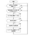
- FIG. 3 is a flowchart illustrating the operation of the mobile terminal according to the first embodiment.
- FIG. 10 is a diagram illustrating a display example of a display screen by a mobile terminal in Embodiment 2.
- FIG. 10 is a diagram illustrating a display example of a display screen by a mobile terminal in Embodiment 3.
- FIG. 10 is a diagram illustrating a display example of a display screen by a mobile terminal according to a fourth embodiment. 10 is a flowchart illustrating the operation of the mobile terminal according to the fourth embodiment. It is a figure which shows the external appearance of the portable terminal in Embodiment 5.
- FIG. FIG. 10 is a diagram for explaining an operation of recognizing an operator by a mobile terminal in the fifth embodiment.
- FIG. 10 is a diagram for explaining an operation of recognizing an operator by a mobile terminal in the fifth embodiment.
- FIG. 10 is a flowchart illustrating an operation of the mobile terminal according to the fifth embodiment.
- FIG. 16 is a diagram for explaining an operation of recognizing an operator by a mobile terminal in the sixth embodiment.
- FIG. 10 is a diagram illustrating a display example of a display screen by a mobile terminal according to a sixth embodiment.
- FIG. 15 is a diagram for explaining an operation of recognizing an operator by a mobile terminal in the seventh embodiment.
- FIG. 20 is a diagram for describing contact input sensitivity setting in a mobile terminal according to an eighth embodiment. It is a functional block diagram which shows the structure of the information processing terminal in attachment 1 of this invention.
- FIGS. 1 and 2 are diagrams illustrating a configuration of a mobile terminal according to the present embodiment.
- 3 to 4 are diagrams illustrating an operation of recognizing the operator by the mobile terminal.
- 5 to 6 are diagrams showing display examples of the display screen by the portable terminal, and
- FIG. 7 is a flowchart showing the operation of the portable terminal.
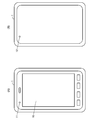
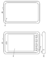
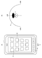
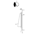
- FIG. 1 is a diagram showing an appearance of a mobile terminal 1 according to the present invention, and FIGS. 1A and 1B are respectively viewed from one surface (front surface) and the other surface (back surface) of the mobile terminal 1. Appearance is shown.
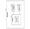
- FIG. 2 is a block diagram showing a circuit configuration of the mobile terminal 1.
- the mobile terminal 1 is a general information processing terminal including a CPU 15 that is a central processing unit, and a Flash ROM 16 and a RAM 17 that are storage devices for storing various data.
- the CPU 15 is connected to each circuit and device in the terminal via a bus.
- the Flash ROM 16 is a rewritable storage memory that stores various control programs to be executed by the CPU 15 and user data.
- a RAM 17 random access memory
- the mobile terminal 1 is described as an example of a mobile phone terminal such as a so-called smartphone.
- the mobile terminal 1 is a PHS (Personal Handy-phone System), PDA (Personal Data). Assistance, Personal ⁇ ⁇ Digital Assistants (personal portable information communication devices), tablet terminals, personal computers, game terminals, electronic dictionaries, car navigation systems, and other information processing apparatuses may be used.
- PHS Personal Handy-phone System
- PDA Personal Data
- Assistance Personal ⁇ ⁇ Digital Assistants
- tablet terminals personal computers
- game terminals electronic dictionaries
- car navigation systems and other information processing apparatuses
- the mobile terminal 1 includes a touch panel type display device 10 on the surface.
- the touch panel display device 10 includes, for example, an input device that receives contact input from an operator such as an electrostatic touch panel, and a display device such as a liquid crystal panel or an organic EL, and the display surface of the display device is a touch panel. It constitutes an input device.
- the mobile terminal 1 includes a display control unit 21 (control device) that controls the display state of the display device constituting the touch panel type display device 10.
- the display control unit 21 is connected to the CPU 15 and displays icons and the like displayed on the display screen of the touch panel display device 10 according to the position (specific position) detected by the operator as described later. It controls the display state of data.
- the display control unit 21 is constructed by incorporating a program into the CPU 15, or is constructed by a dedicated arithmetic device.
- the mobile terminal 1 includes an input detection unit (contact detection unit) 22 that detects a contact input to the input device that constitutes the touch panel type display device 10.
- the input detection part 22 is connected to the said CPU15, and detects and receives the contact input with respect to the display location of display data, such as the icon displayed on a display screen so that it may mention later. That is, when the display area such as the display area or display range of the display data changes, the input detection unit 22 has a function of detecting a contact input performed on the display range.
- the input detection unit 22 is constructed by incorporating a program into the CPU 15 or constructed by a dedicated arithmetic device.
- the mobile terminal 1 includes a camera sensor unit 11 that captures an image on one surface on which the touch panel display device 10 is provided.
- the camera sensor unit 11 is an image sensor such as a CCD image sensor or a CMOS sensor, for example.
- the mobile terminal 1 includes a camera control unit 10 that is a circuit that controls an image sensor that is the camera sensor unit 11.
- the camera control unit 10 sends the captured image data to the CPU 15, and the CPU 15 detects the position of the operator from the data content of the image data as a specific position, as will be described later. That is, the camera sensor unit 11, the camera control unit 23, and the CPU 15 cooperate to function as a position detection unit that detects the position of the operator.
- the position may be detected as a specific position.
- the mobile terminal 1 includes a proximity sensor unit 12 on a surface opposite to the surface on which the touch panel type display device 10 is mounted.
- the proximity sensor unit 12 is a sensor that detects the distance to the object. For example, when the distance to the object is equal to or less than a reference value, the mobile terminal 1 is in contact with a plane such as a desk or a wall such as the desk D. Is detected and notified to the CPU 15.
- the mobile terminal 1 includes a triaxial acceleration sensor unit 13 therein.
- the triaxial acceleration sensor 13 detects the inclination angle of the mobile terminal 1 with respect to the horizontal plane by detecting the acceleration of the mobile terminal 1 in the triaxial direction with respect to the earth's attractive force, and notifies the CPU 15 of the detected inclination angle.
- the CPU 15 detects that the portable terminal 1 is in contact with an object using the proximity sensor unit 12, and the inclination angle of the portable terminal 1 detected by the three-axis acceleration sensor unit 13 is horizontal. If it is determined that there is, it is detected that the mobile terminal 1 is placed horizontally on a predetermined table. That is, the proximity sensor unit 12, the triaxial acceleration sensor unit 13, and the CPU 15 function in cooperation with each other as a horizontal state detection unit that detects that the mobile terminal 1 is in a horizontal state.
- the horizontal state in the present invention means that the inclination angle of the mobile terminal 1 detected by the three-axis acceleration sensor unit 13 described above is within a preset range (for example, an inclination angle of 5 degrees with respect to the horizontal plane). It is also included when it is within the range. Further, the condition for determining that the mobile terminal 1 is in the horizontal state is not necessarily placed on an object such as a table. That is, the mobile terminal 1 is not necessarily limited to including the proximity sensor unit 12. Further, the means for detecting that the mobile terminal 1 is in the horizontal state is not limited to being realized by the above-described configuration, and may be realized by another configuration.
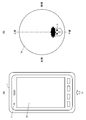
- a position detection unit configured by the camera sensor unit 11 and the CPU 15 performs image recognition processing of image data captured by the camera sensor unit 11 and identifies in which direction the operator is positioned. Specifically, in the present embodiment, as shown in FIG. 3, first, image data in a range indicated by a symbol R shown in FIGS. 3 and 4 is obtained by the camera sensor unit 11 provided on the upper end side of the mobile terminal 1. To be acquired. Thereafter, the CPU 15 executes image recognition processing on the image data in the RAM 17 and performs person (face) detection processing.
- matching is performed with human face feature data stored in advance, or a characteristic portion such as a human eye or mouth is detected by a statistical method.
- a characteristic portion such as a human eye or mouth is detected by a statistical method.
- the operator U's face is detected on the lower end side, so that the operator U is shown in FIG. It is detected as being located in the horizontal direction with respect to the portable terminal 1 and located on the lower end side of FIG.
- the imaging range R of FIG. 4B when the operator U is located on the end side in a specific direction, the operator U is located on each end side and in the horizontal direction of the mobile terminal 1. If the operator U is located in the center of the shooting range R, it is detected that the operator U is vertically above the mobile terminal 1.
- the above-described detection of the position of the operator U is not necessarily performed using a captured image. You may implement
- the display control unit 21 detects that the mobile terminal 1 is placed in a horizontal state and the operator U is positioned in a specific horizontal direction with respect to the mobile terminal 1 as described above.
- the display state of the display screen of the touch panel type display device 10 is changed and displayed. Specifically, the display control unit 21 first recognizes that the display screen is viewed from the end side in a specific direction of the mobile terminal 1 where the operator U is located, and the end side is the lower side of the display screen.
- the display orientation of the display data displayed on the touch panel display device 10 is changed so that The display control unit 21 further displays the display state of the display data according to the distance from the detected position (specific position) of the operator U to the display area occupied by the display data on the display screen of the touch panel display device 10.
- the display state of the icons and the entire screen is changed and displayed. To do.
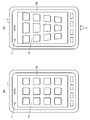
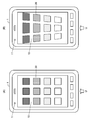
- the display control unit 21 controls to display a plurality of rectangular icons 20 on the display screen of the touch panel display device 10 as shown in FIG. 5A as a normal display state.
- the display direction is such that the lower side of the display data faces the lower end side of FIG. From such a state, the portable terminal 1 is placed on the desk D or the like and becomes horizontal, and the position of the operator U is horizontal with respect to the portable terminal 1 as shown in FIG.
- the touch panel type display device 10 is such that the end side is on the lower side of the display screen. Change the display direction of the data displayed on the screen. However, in the example of FIG. 5B, the display orientation is not changed with respect to FIG.
- the shape of the icon 20 is described as a rectangular shape. However, the shape of the icon 20 is not limited to a rectangular shape, and may be, for example, a circular shape or any shape.
- the display control unit 21 changes the display shape of each square icon 20 that is display data displayed on the display screen from a specific end of the mobile terminal 1.
- the display is changed to a trapezoidal shape so as to increase as the distance of the display increases.
- the display shape of each icon 20 is changed to a trapezoidal shape in which the width located on the operator U side is short and the width located far from the operator U is long as compared to the normal display.
- the trapezoidal display size is enlarged and displayed as the icon 20 is located farther from the operator U. Thereby, each icon 20 is displayed so that the operator U can feel a sense of perspective more strongly, and the operator U can easily recognize the icon 20 located farther away.
- each icon 20 is relative to the distance direction. Determine the position. For example, with respect to a specific end portion of the mobile terminal 1, an icon 20 existing at a position farthest in the distance direction and an icon 20 present at the latest position are respectively displayed as an icon 20 at the distal end and an icon at the proximal end. 20 is determined. In addition, you may consider that the icon displayed in parallel with respect to the specific edge part of the portable terminal 1 exists in the same position with respect to the distance direction. And according to the relative distance with respect to the specific edge part which each icon 20 has, the display mode change process with respect to each icon 20 is performed.
- the display mode changing process is, for example, changing the shape so that each icon 20 becomes a trapezoid as described above, and then reducing the ratio of the data size of each icon 20 from distal to proximal. Alternatively, it is a process of displaying the image by changing its size, such as enlarging from proximal to distal. Alternatively, in the display mode change process, only one of the above-described shape change and enlargement / reduction process may be performed.
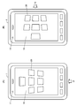
- the change in the display state of the icon 20 in FIG. 5B is an example, and the icon 20 may be displayed in a different shape. Further, the size of the icon 20 is not necessarily changed, and the image element added to the icon 20 may be changed as described in other embodiments. Further, in the above, the case where the shape of each icon 20 is changed and displayed is exemplified, but as shown in FIG. 6A, the display data 20 ′ displayed on the entire touch panel display device 10 is displayed as follows. As shown in FIG. 6B, the entire screen is displayed so that the width of the end side where the operator U is positioned is gradually shortened, and the width of the end side opposite to the end side becomes longer. It is also possible to display as follows.
- the positions of the distal and proximal positions of the entire screen in the direction of the distance from the specific end of the mobile terminal 1 to the screen are determined, and the entire screen is trapezoidal so that the entire screen becomes a trapezoid.
- the ratio of the data size is displayed decreasing from the distal to the proximal, or enlarged from the proximal to the distal.
- the input detection unit 22 performs a process of changing a range in which contact input to the icon 20 is detected. That is, in the normal display state shown in FIG. 5A, the input detection unit 22 receives the contact input when detecting the contact input on the square icon 20, but after the change display in FIG. Detects a contact input to the range of the shape of the icon 20 which is a trapezoid, and accepts the input.
- the display state changing process by the display control unit 21 described above is executed according to the position of the operator U even when the touch panel display device 10 of the mobile terminal 1 is not positioned in the horizontal state. Also good.
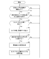
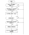
- the proximity sensor 12 disposed on the back surface of the mobile terminal 1 detects the distance to the proximity object. If the distance to the proximity object is closer than a preset threshold value, the mobile terminal 1 determines that it is in contact with the proximity object (Yes in step S1).
- the installation angle of the mobile terminal 1 is detected from the detection value obtained by the triaxial acceleration sensor 13 provided in the mobile terminal 1. If the installation angle of the mobile terminal 1 is within a preset threshold with respect to an angle perpendicular to the direction of gravity of the earth, it is determined that the mobile terminal 1 is installed horizontally (Yes in step S2).
- step S3 when the portable terminal 1 contacts the proximity
- the image data output from the camera control unit 23 is sent to the RAM 17, and an image recognition process is performed by the CPU 15 to identify in which direction the position of the operator U is located on the mobile terminal 1. At this time, if it is determined that the position of the operator U is in the center of the captured image data, it is determined that the operator U is vertically above the mobile terminal 1. On the other hand, when the operator U is located at the end of the mobile terminal 1 in a specific direction in the image data, the operator U is identified as operating from a position near the horizontal in the specific direction of the mobile terminal 1. (Yes in step S5). For example, in the example of FIG.
- the mobile terminal 1 placed horizontally is identified as being operated in the direction of the arrow from the horizontal plane.
- the display state on the display screen of the touch panel type display device 10 is changed (step S6).
- the lower end side of the mobile terminal 1 becomes the lower side of the display screen.
- Change the display orientation Compared with the normal display state of FIG. 5A, the length in the width direction on the lower side of the screen display located on the operator U side, that is, on the front side of the operator U is shorter.
- the display screen is changed to a trapezoidal display screen in which the length in the width direction on the upper side of the screen display located on the far side is longer. Thereby, the operator U becomes easier to see the screen display located far away.
- the operation area for detecting contact input to the touch panel type display device 10 is also changed to a trapezoid corresponding to the display area (step S7).
- the operator U can perform an operation corresponding to the screen display, and can easily perform the operation.
- the present invention even when the operator U looks at the mobile terminal 1 from the horizontal direction while the mobile terminal 1 is installed horizontally on a desk or the like, the perspective of the display content is reduced. Is more strongly reflected and displayed, so that the operator U can easily confirm the display contents and the operability is improved.
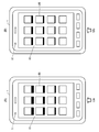
- FIG. 8 is a diagram illustrating a display example of the display screen of the mobile terminal according to the present embodiment.
- the mobile terminal 1 in the present embodiment has a configuration substantially similar to that of the above-described first embodiment, but the method of change display according to the position of the operator U by the display control unit 21 is different.
- the display control unit 21 in the present embodiment detects that the mobile terminal 1 is placed in a horizontal state and the operator U is positioned in a specific horizontal direction with respect to the mobile terminal 1. Then, according to the distance from the detected position of the operator U to the display position of the display data on the display screen of the touch panel type display device 10, the icon 20 and the display color density and brightness of the entire screen are changed and displayed. .
- the position of the operator U can be identified on the lower end side (arrow position) of the mobile terminal 1 as shown in FIG. 8A with respect to the normal display state described in FIG.
- the display density of the icon 20 located close to the operator U is light, and the display density of the icon 20 located far is displayed dark.
- the display density on the side closer to the operator U may be darker and the display density on the side farther away may be displayed lighter.
- the luminance of the display screen may be changed according to the distance from the operator U as well. For example, the brightness on the side located closer to the operator U may be darkened, and the brightness on the far side may be brighter, or vice versa.
- the display density of the icon 20 displayed by changing the shape and size in the first embodiment is changed according to the position from the operator U as in FIG. 8A. It is an example when it is displayed.
- FIG. 9 is a diagram illustrating a display example of the display screen of the mobile terminal according to the present embodiment.
- the mobile terminal 1 in the present embodiment has a configuration substantially similar to that of the above-described first embodiment, but the method of change display according to the position of the operator U by the display control unit 21 is different.
- the display control unit 21 in the present embodiment detects that the mobile terminal 1 is placed in a horizontal state and the operator U is positioned in a specific horizontal direction with respect to the mobile terminal 1. Then, according to the distance from the detected position of the operator U to the display area of the display data on the display screen of the touch panel type display device 10, the display area occupied by the shadow display displayed in the vicinity of the display area of each icon 20 Change the height of the 3D display.
- the display control unit 21 sets the position of the operator U on the lower end side (arrow position) of the mobile terminal 1 as shown in FIG. 9A with respect to the normal display state described in FIG. If it can be identified, a black shadow display is displayed small (shallow) behind the icon 20 located close to the operator U, and a black shadow is displayed below the icon 20 located far away. Display the display larger (deeper).
- FIG. 9B shows a shadow display having a different size according to the position from the operator U, similarly to FIG. 9A, on the icon 20 displayed with the shape and size changed in the first embodiment. This is an example when is displayed.
- the display control unit 21 changes the display area of the shadow display in the same manner as the process for changing the display mode of each icon 20 described above. That is, the direction of the distance from the specific end of the mobile terminal 1 to each icon 20 is specified, and the relative position of each icon 20 with respect to the distance direction is determined. For example, with respect to a specific end portion of the mobile terminal 1, the icon 20 existing at the position farthest in the distance direction and the icon 20 at the most recent position, respectively, the icon 20 at the distal position and the icon 20 at the proximal position, respectively. The icon 20 is determined. In addition, you may consider that all the icons displayed in parallel with respect to the specific edge part of the portable terminal 1 exist in the same position with respect to the distance direction.
- the shadow display changing process is, for example, reducing the ratio of the data size of the shadow display of each icon 20 from the distal to the proximal so that it becomes a trapezoid like each icon 20 as described above. Or it is the process which changes and displays the size of shadow display itself, such as enlarging from proximal to distal.
- the icon 20 may be displayed in a three-dimensional manner so as to exhibit a three-dimensional visual effect. That is, when the mobile terminal 1 is arranged horizontally and the position of the operator U with respect to the terminal 1 can be identified, the three-dimensional image is displayed such that the higher the distance from the operator U is, the higher the height is displayed. The display may be displayed along with the lower side behind the icon 20.
- FIG. 10 is a diagram illustrating a display example of the display screen of the mobile terminal in the present embodiment
- FIG. 11 is a flowchart illustrating the operation of the mobile terminal.
- the mobile terminal 1 according to the present embodiment has substantially the same configuration as that of the first embodiment described above. However, the position of the operator U is always detected, and each of the above-described positions is determined according to the changed position of the operator U. It differs in that it is changed and displayed as in the embodiment.
- step S1 and S2 in FIG. 7 it is detected that the mobile terminal 1 is placed in a horizontal state (steps S1 and S2 in FIG. 7), and when pressing on the touch panel display device 10 is detected (step S3 in FIG. 7). )),
- the display was controlled by operating the camera to detect the position of the operator U (steps S4 to S7 in FIG. 7).
- step S11 and S12 in FIG. 11 when it is detected that the mobile terminal 1 is placed in a horizontal state (steps S11 and S12 in FIG. 11), the camera is operated (step S13 in FIG. 11) to capture the captured image. It is determined whether the operator U exists in the data (step S14 in FIG. 11).
- image recognition processing is performed on the image data, and parts such as the face outline, eyes, nose, mouth, and the like existing in the image data are extracted based on preset criteria, thereby The presence is detected and it is determined that the operator U exists.
- the position of the operator U with respect to the portable terminal 1 is detected, and display control is performed corresponding to the position (steps S15 to S17 in FIG. 11).
- FIG. 10A when it is detected that the operator U is located on the lower end side (see the arrow) of the mobile terminal 1, the display screen is displayed in the same manner as in the first embodiment.
- Each of the rectangular icons 20 that are display data displayed on the screen is deformed and displayed in a trapezoidal shape so as to increase as the distance from a specific end of the mobile terminal 1 increases.
- the mobile terminal 1 first determines that the operator U uses the mobile terminal 1 from the image data that is always captured by the camera sensor unit 11. It is detected that it is located on the right end side.
- the display direction of the display data displayed on the mold display device 10 is changed. That is, the display on the display screen shown in FIG. 10A is rotated 90 degrees counterclockwise and displayed in the direction shown in FIG. In this case as well, each square icon 20 that is display data displayed on the display screen is displayed in a trapezoidal shape so as to increase as the distance from the specific end of the mobile terminal 1 increases. To do.
- the display data change display according to the distance from the operator U may be performed as described in the above-described embodiments.
- FIG. 12 is a diagram illustrating an external configuration of the mobile terminal according to the present embodiment.
- 13 to 14 are diagrams for explaining an operation of recognizing an operator by the mobile terminal.
- FIG. 15 is a flowchart showing the operation of the mobile terminal.
- the portable terminal 1 in this embodiment has the structure substantially the same as the thing of each embodiment mentioned above, the camera sensor part 11a is provided in the side surface located in the lower end part of the portable terminal 1, as shown in FIG. It differs in that it is equipped.
- the camera sensor unit 11a is mounted on a specific side surface of the mobile terminal 1, only the specific side surface direction of the mobile terminal 1 becomes the imaging range R as shown in FIG.
- the image data as shown in FIG. Note that image data is captured by operating the camera when it is detected that the mobile terminal 1 is placed in a horizontal state (steps S21 and S22 in FIG. 15), as in the fourth embodiment described above (FIG. 15). 15 step S23).
- step S24 in FIG. 15 it is determined whether or not the operator U exists in the captured image data.
- the operator U for example, by performing image recognition processing on the image data and extracting parts such as the face outline, eyes, nose, and mouth existing in the image data, the presence of the human face is detected, and the operator U Is determined to exist. Accordingly, it is determined that the operator U is located on the side in the side surface direction where the camera sensor unit 11a is equipped, and display control is performed as shown in FIG. Steps S25 and S26 in FIG.
- the display data change display according to the distance from the operator U may be performed as described in the above-described embodiments.
- the camera sensor unit 11a is mounted only on the side surface located at the lower end of the four side surfaces of the mobile terminal 1 .
- it may be mounted on the other side surface.
- you may equip several side surface with the camera sensor part 11a.
- the side where the camera sensor unit 11a that detects the operator U is specified is specified, and the operator U is positioned on the side of the side of the side, and the same display change is performed.
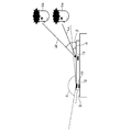
- FIG. 16 is a diagram for explaining the operation of recognizing the operator by the mobile terminal.
- FIG. 17 is a diagram illustrating a display example of the display screen of the mobile terminal.
- the portable terminal 1 in the present embodiment has a configuration that is almost the same as that of each of the above-described embodiments, but the method of change display according to the position of the operator U by the display control unit 21 is different.
- the display control unit 21 in the present embodiment detects that the mobile terminal 1 is placed in a horizontal state and the operator U is positioned in a specific horizontal direction with respect to the mobile terminal 1. Then, the display state is changed according to the distance from the position of the operator U, and the display state is also changed according to the angle with respect to the display surface of the operator U and the touch panel type display device 10.
- the position of the operator is a position indicated by a symbol Ua and a symbol Ub.
- the line of sight La from the operator Ua to the display position of the display data has an angle ⁇ with respect to the display screen
- the line of sight Lb from the operator Ub to the display position of the display data has an angle with respect to the display screen. ⁇ , which is different.
- the operator Ua since the operator Ua has a smaller line-of-sight angle with respect to the display screen than the operator Ub, the operator Ua is usually less likely to visually recognize the display data.
- the mobile terminal 1 first sets parts such as a face outline, eyes, nose, and mouth that are present in the image data captured by the camera sensor unit 11 in advance. Extraction is performed based on the reference, and the height positions of the faces of the operators Ua and Ub with respect to the mobile terminal 1 are specified. At this time, in particular, the height positions of the eyes of the operators Ua and Ub are detected. Then, based on the detected height positions of the operators Ua and Ub, the angles of the operators Ua and Ub with respect to the operation screen are specified, and display control corresponding to the angles is performed.
- the distance from the operator increases as the distance from the operator increases.
- the shadow display to be displayed is displayed in a large size, and the degree of change in the size of the shadow display is changed according to the angles of the operators Ua and Ub. That is, when performing a shadow display on the icon 20 displayed at the same position on the display screen, the shadow display (FIG. 16A) for the operator Ua having a smaller angle with respect to the display screen is more effective than the operator Ua. Also, the display is larger than the shading display (FIG. 16B) for the operator Ub having a large angle with respect to the display screen. Thereby, although the operator Ua has a small angle of the line of sight with respect to the display screen, it becomes easier to visually recognize the display data.
- the size of the shadow display is changed depending on the angle.
- the size and shape of the display data are changed, and the display color is displayed. You may change according to the angle of the position of the operator with respect to a screen.
- FIG. 18 is a diagram for explaining the operation of recognizing the operator by the mobile terminal.
- the mobile terminal 1 in the present embodiment has substantially the same configuration as that of each of the above-described embodiments, but the position of a specific operator U set in advance from image data captured by the camera sensor unit 11 It has a feature in that it has a function of specifying.
- the portable terminal 1 specifies one operator U. For example, all facial contours, eyes, nose, mouth, and other parts existing in the image data are extracted based on preset criteria, and the operator with the largest specific contour or facial contour is identified.
- the operator U located on the lower end side is specified.
- the icon 20 is changed and displayed according to the specified position of the operator U.
- a rule for specifying one operator U from the image data is set in advance, but the operator U may be specified by another rule.
- the position of the operator who is present in the image data last may be specified within a preset time, or the position of a specific operator in which face feature data is stored in advance may be specified.
- an operation such as blinking of the operator existing in the image data may be detected, and the position of the operator who performed the operation may be specified.
- FIG. 19 is a diagram for explaining the operation of recognizing the operator by the mobile terminal.
- the portable terminal 1 in this embodiment has the structure substantially the same as that of each embodiment mentioned above, according to the distance of the touch panel type display apparatus 10 from the position of the operator U, the input detection part 22 is according to the distance. The difference is that it has a function of changing the sensitivity of contact input to the touch panel type display device 10.
- the mobile terminal 1 when it is detected that the operator U is located on the lower end side (see the arrow) of the mobile terminal 1, first, according to the distance from the position of the operator U as described above. The display state is changed, and at the same time, the sensitivity S for detecting the touch input is set to be higher as the distance from the position of the operator U is longer.
- symbol S of FIG. 19 represents the height of the sensitivity S of contact input visually.
- the operator U performs input by pressing the touch panel with a normal pressing force to a position located near the touch panel type display device 10, but far away such as near the upper end of the mobile terminal 1. It is possible to input a position with a smaller pressing force, for example, a light touch.
- the sensitivity S for detecting contact input may be set higher as the distance from the position of the operator U increases.
- the operator 10 can obtain a visual sense that the display data located farther away is located above the display screen, and the operation such as pressing input to the display data can be performed with a light contact.
- the visual sensation matches the operational sensation, and the operability can be improved.
- a touch panel display device 110 A control device 120 for controlling a display state of the touch panel display device 110; Position detecting means 130 for detecting a specific position with respect to the touch panel type display device 110, The control device 120 changes the display state of the display data according to the distance between the specific position detected by the position detection unit 130 and the display area occupied by the display data on the touch panel display device 110.
- Part 121 Information processing terminal 100.
- (Appendix 2) An information processing terminal according to attachment 1, wherein The display control unit determines positions to be distal and proximal on the display area in the direction of the distance from the specific position to the display data, and changes a display state from the distal to the proximal. indicate, Information processing terminal.
- Appendix 4 An information processing terminal according to appendix 2 or 3, The display control unit displays the ratio of the data size of the display data in a reduced manner from the distal to the proximal, or in an enlarged manner from the proximal to the distal. Information processing terminal.
- Appendix 5 An information processing terminal according to any one of appendices 1 to 4, The display control unit changes a display area occupied by shadow display data displayed in the vicinity of a display area of display data displayed on the touch panel type display device according to the distance. Information processing terminal.
- Appendix 6 An information processing terminal according to any one of appendices 1 to 5, The display control unit changes the height of stereoscopic display displayed in the vicinity of a display area of display data displayed on the touch panel type display device according to the distance. Information processing terminal.
- Appendix 7 An information processing terminal according to any one of appendices 1 to 6, The display control unit changes a display color density of display data displayed on the touch panel display device according to the distance; Information processing terminal.
- Appendix 8 An information processing terminal according to any one of appendices 1 to 7, The display control unit changes the luminance of the display color of display data displayed on the touch panel display device according to the distance. Information processing terminal.
- the display control unit is configured to display the display data according to an angle from the specific position detected by the position detection unit to a display position of display data on the touch panel display device with respect to a display surface of the touch panel display device. Change the display status of Information processing terminal.
- the control device includes a contact detection unit that detects a contact input to the touch panel display device, The contact detection unit changes a range in which contact input to the display data is detected according to a change in the display state of the display data by the display control unit.
- Information processing terminal includes a contact detection unit that detects a contact input to the touch panel display device, The contact detection unit changes a range in which contact input to the display data is detected according to a change in the display state of the display data by the display control unit.
- the control device includes a contact detection unit that detects a contact input to the touch panel display device,
- the contact detection unit has a sensitivity for detecting a contact input to the touch panel display device according to a distance between the specific position detected by the position detection unit and a display position of display data on the touch panel display device. change, Information processing terminal.
- Appendix 12 An information processing terminal according to any one of appendices 1 to 11, A horizontal state detecting means for detecting that the display surface of the touch panel type display device is in a horizontal state based on a preset reference; The display control unit changes and displays the display state of the display data when the touch panel type display device is in a horizontal state by the horizontal state detection means. Information processing terminal.
- the position detection means detects a specific person set in advance at the specific position;
- the display control unit changes a display state of the display data according to a distance between the position of the specific person detected by the position detection unit and a display position of display data on the touch panel display device.
- Information processing terminal An information processing terminal according to any one of appendices 1 to 12,
- the position detection means detects a specific person set in advance at the specific position;
- the display control unit changes a display state of the display data according to a distance between the position of the specific person detected by the position detection unit and a display position of display data on the touch panel display device.
- Position detecting means for detecting a specific position with respect to the touch panel type display device;
- the display state of the display data is controlled according to the distance between the specific position detected by the position detector and the display area occupied by the display data on the touch panel display device, while controlling the display state of the touch panel display device.
- Appendix 15 The program according to appendix 14, wherein The display control unit determines positions to be distal and proximal on the display area in the direction of the distance from the specific position to the display data, and changes a display state from the distal to the proximal. indicate, program.
- the programs described in the above embodiments and supplementary notes are stored in a storage device or recorded on a computer-readable recording medium.
- the recording medium is a portable medium such as a flexible disk, an optical disk, a magneto-optical disk, and a semiconductor memory.
Landscapes
- Engineering & Computer Science (AREA)
- Theoretical Computer Science (AREA)
- General Engineering & Computer Science (AREA)
- Computer Hardware Design (AREA)
- Human Computer Interaction (AREA)
- Physics & Mathematics (AREA)
- General Physics & Mathematics (AREA)
- User Interface Of Digital Computer (AREA)
- Position Input By Displaying (AREA)
Abstract
Priority Applications (2)
| Application Number | Priority Date | Filing Date | Title |
|---|---|---|---|
| EP12835441.2A EP2763010A4 (fr) | 2011-09-26 | 2012-09-18 | Terminal de traitement d'informations mobile |
| US14/347,186 US20140300570A1 (en) | 2011-09-26 | 2012-09-18 | Mobile information processing terminal |
Applications Claiming Priority (2)
| Application Number | Priority Date | Filing Date | Title |
|---|---|---|---|
| JP2011-208567 | 2011-09-26 | ||
| JP2011208567 | 2011-09-26 |
Publications (1)
| Publication Number | Publication Date |
|---|---|
| WO2013046596A1 true WO2013046596A1 (fr) | 2013-04-04 |
Family
ID=47994682
Family Applications (1)
| Application Number | Title | Priority Date | Filing Date |
|---|---|---|---|
| PCT/JP2012/005929 WO2013046596A1 (fr) | 2011-09-26 | 2012-09-18 | Terminal de traitement d'informations mobile |
Country Status (4)
| Country | Link |
|---|---|
| US (1) | US20140300570A1 (fr) |
| EP (1) | EP2763010A4 (fr) |
| JP (1) | JPWO2013046596A1 (fr) |
| WO (1) | WO2013046596A1 (fr) |
Cited By (9)
| Publication number | Priority date | Publication date | Assignee | Title |
|---|---|---|---|---|
| JP2015061298A (ja) * | 2013-09-20 | 2015-03-30 | シャープ株式会社 | 携帯端末、および制御方法 |
| JP2016038720A (ja) * | 2014-08-07 | 2016-03-22 | 本田技研工業株式会社 | 電子装置及び該電子装置を搭載した車両 |
| JP2016224595A (ja) * | 2015-05-28 | 2016-12-28 | 株式会社コロプラ | システム、方法、およびプログラム |
| JP2017045333A (ja) * | 2015-08-27 | 2017-03-02 | 京セラドキュメントソリューションズ株式会社 | 表示装置および表示制御プログラム |
| CN106488063A (zh) * | 2015-08-27 | 2017-03-08 | 京瓷办公信息系统株式会社 | 显示装置 |
| JP2017050620A (ja) * | 2015-08-31 | 2017-03-09 | 京セラドキュメントソリューションズ株式会社 | 表示装置および表示制御プログラム |
| JP2017049664A (ja) * | 2015-08-31 | 2017-03-09 | 京セラドキュメントソリューションズ株式会社 | 表示装置および表示制御プログラム |
| JPWO2015151387A1 (ja) * | 2014-04-04 | 2017-04-13 | ソニー株式会社 | 画像処理装置、画像処理方法及びプログラム |
| JP2020503599A (ja) * | 2016-12-14 | 2020-01-30 | サムスン エレクトロニクス カンパニー リミテッド | ディスプレイ装置及びその制御方法 |
Families Citing this family (3)
| Publication number | Priority date | Publication date | Assignee | Title |
|---|---|---|---|---|
| CA2857531A1 (fr) * | 2011-12-08 | 2013-06-13 | Exo U Inc. | Procede pour ameliorer une interaction avec une interface utilisateur affichee sur un dispositif d'affichage a ecran tactile 3d |
| CN102945520A (zh) * | 2012-11-02 | 2013-02-27 | 中兴通讯股份有限公司 | 一种设备管理系统及方法 |
| CN106648413B (zh) * | 2016-09-28 | 2020-07-28 | 北京小米移动软件有限公司 | 基于手机的可操作区域的处理方法和装置 |
Citations (5)
| Publication number | Priority date | Publication date | Assignee | Title |
|---|---|---|---|---|
| JP2007017596A (ja) | 2005-07-06 | 2007-01-25 | Matsushita Electric Ind Co Ltd | 携帯端末装置 |
| WO2008041312A1 (fr) * | 2006-10-02 | 2008-04-10 | Pioneer Corporation | Dispositif d'affichage d'images |
| JP2009157908A (ja) * | 2007-12-07 | 2009-07-16 | Sony Corp | 情報表示端末、情報表示方法、およびプログラム |
| WO2011064895A1 (fr) * | 2009-11-30 | 2011-06-03 | パイオニア株式会社 | Dispositif d'affichage de carte, procédé d'affichage de carte, programme d'affichage de carte, et support d'enregistrement |
| JP2011175617A (ja) * | 2010-01-29 | 2011-09-08 | Shimane Prefecture | 画像認識装置および操作判定方法並びにプログラム |
Family Cites Families (16)
| Publication number | Priority date | Publication date | Assignee | Title |
|---|---|---|---|---|
| JP3658537B2 (ja) * | 2000-06-27 | 2005-06-08 | シャープ株式会社 | 情報記録表示装置 |
| US8736557B2 (en) * | 2006-09-11 | 2014-05-27 | Apple Inc. | Electronic device with image based browsers |
| US8462109B2 (en) * | 2007-01-05 | 2013-06-11 | Invensense, Inc. | Controlling and accessing content using motion processing on mobile devices |
| US20090156970A1 (en) * | 2007-12-14 | 2009-06-18 | Sullivan Shannon E | System and method for exercising eyes |
| KR101495164B1 (ko) * | 2008-04-10 | 2015-02-24 | 엘지전자 주식회사 | 이동단말기 및 그 화면 처리 방법 |
| JP2010004118A (ja) * | 2008-06-18 | 2010-01-07 | Olympus Corp | デジタルフォトフレーム、情報処理システム、制御方法、プログラム及び情報記憶媒体 |
| JP5328810B2 (ja) * | 2008-12-25 | 2013-10-30 | パナソニック株式会社 | 情報表示装置および情報表示方法 |
| JP5374170B2 (ja) * | 2009-01-22 | 2013-12-25 | 任天堂株式会社 | 情報処理プログラム、情報処理装置、情報処理システムおよび情報処理方法 |
| US8179449B2 (en) * | 2009-05-20 | 2012-05-15 | Sony Ericsson Mobile Communications Ab | Portable electronic apparatus including a display and method for controlling display content based on movement of the display and user position |
| US8373669B2 (en) * | 2009-07-21 | 2013-02-12 | Cisco Technology, Inc. | Gradual proximity touch screen |
| KR20110052998A (ko) * | 2009-11-13 | 2011-05-19 | 삼성전자주식회사 | 디바이스에서 사용자 인터페이스 제공 방법 및 장치 |
| KR20110101585A (ko) * | 2010-03-09 | 2011-09-16 | 삼성전자주식회사 | 휴대용 단말기의 화면 전환 장치 및 방법 |
| JP2011223556A (ja) * | 2010-03-25 | 2011-11-04 | Kyocera Corp | 携帯端末装置 |
| JP5573379B2 (ja) * | 2010-06-07 | 2014-08-20 | ソニー株式会社 | 情報表示装置および表示画像制御方法 |
| JP2012038164A (ja) * | 2010-08-09 | 2012-02-23 | Sony Corp | 情報処理装置 |
| JP5732784B2 (ja) * | 2010-09-07 | 2015-06-10 | ソニー株式会社 | 情報処理装置、情報処理方法およびコンピュータプログラム |
-
2012
- 2012-09-18 EP EP12835441.2A patent/EP2763010A4/fr not_active Withdrawn
- 2012-09-18 US US14/347,186 patent/US20140300570A1/en not_active Abandoned
- 2012-09-18 WO PCT/JP2012/005929 patent/WO2013046596A1/fr active Application Filing
- 2012-09-18 JP JP2013535877A patent/JPWO2013046596A1/ja active Pending
Patent Citations (5)
| Publication number | Priority date | Publication date | Assignee | Title |
|---|---|---|---|---|
| JP2007017596A (ja) | 2005-07-06 | 2007-01-25 | Matsushita Electric Ind Co Ltd | 携帯端末装置 |
| WO2008041312A1 (fr) * | 2006-10-02 | 2008-04-10 | Pioneer Corporation | Dispositif d'affichage d'images |
| JP2009157908A (ja) * | 2007-12-07 | 2009-07-16 | Sony Corp | 情報表示端末、情報表示方法、およびプログラム |
| WO2011064895A1 (fr) * | 2009-11-30 | 2011-06-03 | パイオニア株式会社 | Dispositif d'affichage de carte, procédé d'affichage de carte, programme d'affichage de carte, et support d'enregistrement |
| JP2011175617A (ja) * | 2010-01-29 | 2011-09-08 | Shimane Prefecture | 画像認識装置および操作判定方法並びにプログラム |
Non-Patent Citations (1)
| Title |
|---|
| See also references of EP2763010A4 |
Cited By (13)
| Publication number | Priority date | Publication date | Assignee | Title |
|---|---|---|---|---|
| JP2015061298A (ja) * | 2013-09-20 | 2015-03-30 | シャープ株式会社 | 携帯端末、および制御方法 |
| JPWO2015151387A1 (ja) * | 2014-04-04 | 2017-04-13 | ソニー株式会社 | 画像処理装置、画像処理方法及びプログラム |
| US10636384B2 (en) | 2014-04-04 | 2020-04-28 | Sony Corporation | Image processing apparatus and image processing method |
| JP2016038720A (ja) * | 2014-08-07 | 2016-03-22 | 本田技研工業株式会社 | 電子装置及び該電子装置を搭載した車両 |
| JP2016224595A (ja) * | 2015-05-28 | 2016-12-28 | 株式会社コロプラ | システム、方法、およびプログラム |
| CN106488063B (zh) * | 2015-08-27 | 2019-05-28 | 京瓷办公信息系统株式会社 | 显示装置 |
| US10254918B2 (en) | 2015-08-27 | 2019-04-09 | Kyocera Document Solutions Inc. | Tilt adjustable perspective icons display device and non-transitory computer readable medium |
| CN106488063A (zh) * | 2015-08-27 | 2017-03-08 | 京瓷办公信息系统株式会社 | 显示装置 |
| JP2017045333A (ja) * | 2015-08-27 | 2017-03-02 | 京セラドキュメントソリューションズ株式会社 | 表示装置および表示制御プログラム |
| JP2017049664A (ja) * | 2015-08-31 | 2017-03-09 | 京セラドキュメントソリューションズ株式会社 | 表示装置および表示制御プログラム |
| JP2017050620A (ja) * | 2015-08-31 | 2017-03-09 | 京セラドキュメントソリューションズ株式会社 | 表示装置および表示制御プログラム |
| JP2020503599A (ja) * | 2016-12-14 | 2020-01-30 | サムスン エレクトロニクス カンパニー リミテッド | ディスプレイ装置及びその制御方法 |
| JP7050067B2 (ja) | 2016-12-14 | 2022-04-07 | サムスン エレクトロニクス カンパニー リミテッド | ディスプレイ装置及びその制御方法 |
Also Published As
| Publication number | Publication date |
|---|---|
| EP2763010A1 (fr) | 2014-08-06 |
| EP2763010A4 (fr) | 2015-06-03 |
| US20140300570A1 (en) | 2014-10-09 |
| JPWO2013046596A1 (ja) | 2015-03-26 |
Similar Documents
| Publication | Publication Date | Title |
|---|---|---|
| WO2013046596A1 (fr) | Terminal de traitement d'informations mobile | |
| KR102121592B1 (ko) | 시력 보호 방법 및 장치 | |
| US9703939B2 (en) | Mobile terminal and control method thereof | |
| CN103870773B (zh) | 用于显示数据的方法和装置 | |
| KR101806891B1 (ko) | 이동 단말기 및 이동 단말기의 제어방법 | |
| US9007321B2 (en) | Method and apparatus for enlarging a display area | |
| US20160292922A1 (en) | Display control device, display control method, and recording medium | |
| US20160334936A1 (en) | Portable device and method of modifying touched position | |
| JP2019128961A (ja) | 指紋認識のための方法、電子装置及び格納媒体 | |
| US10866649B2 (en) | Gesture identification method and electronic device | |
| JP6046384B2 (ja) | 端末装置 | |
| JP2013150129A (ja) | 携帯端末 | |
| CN111405117B (zh) | 一种控制方法及电子设备 | |
| US11750727B2 (en) | Electronic device including a plurality of displays and method for operating same | |
| EP3614239B1 (fr) | Commande de dispositif électronique en réponse à une rotation des doigts sur un capteur d'empreintes digitales et procédés correspondants | |
| EP4149091A1 (fr) | Dispositif électronique comprenant une pluralité d'affichages et procédé de fonctionnement associé | |
| US20220366874A1 (en) | Eye gaze control of magnification user interface | |
| JP7495459B2 (ja) | 頭部装着型ディスプレイ装置、頭部装着型ディスプレイ装置の制御方法 | |
| CN109104573B (zh) | 一种确定对焦点的方法及终端设备 | |
| JP6792721B2 (ja) | 電子機器、プログラム、制御装置および制御方法 | |
| KR101537625B1 (ko) | 이동단말기 및 그 제어방법 | |
| JP2020017215A (ja) | 電子機器、制御プログラム及び表示制御方法 | |
| US11100903B2 (en) | Electronic device and control method for controlling a display range on a display | |
| US8941648B2 (en) | Mobile terminal and control method thereof | |
| JP2020017218A (ja) | 電子機器、制御プログラム及び表示制御方法 |
Legal Events
| Date | Code | Title | Description |
|---|---|---|---|
| 121 | Ep: the epo has been informed by wipo that ep was designated in this application |
Ref document number: 12835441 Country of ref document: EP Kind code of ref document: A1 |
|
| ENP | Entry into the national phase |
Ref document number: 2013535877 Country of ref document: JP Kind code of ref document: A |
|
| WWE | Wipo information: entry into national phase |
Ref document number: 2012835441 Country of ref document: EP |
|
| WWE | Wipo information: entry into national phase |
Ref document number: 14347186 Country of ref document: US |
|
| NENP | Non-entry into the national phase |
Ref country code: DE |