WO2013046593A1 - Dispositif de génération d'image de vue d'œil d'oiseau, procédé de génération d'image de vue d'œil d'oiseau et programme de génération d'image de vue d'œil d'oiseau - Google Patents
Dispositif de génération d'image de vue d'œil d'oiseau, procédé de génération d'image de vue d'œil d'oiseau et programme de génération d'image de vue d'œil d'oiseau Download PDFInfo
- Publication number
- WO2013046593A1 WO2013046593A1 PCT/JP2012/005923 JP2012005923W WO2013046593A1 WO 2013046593 A1 WO2013046593 A1 WO 2013046593A1 JP 2012005923 W JP2012005923 W JP 2012005923W WO 2013046593 A1 WO2013046593 A1 WO 2013046593A1
- Authority
- WO
- WIPO (PCT)
- Prior art keywords
- image
- overhead
- vehicle
- joint
- image generation
- Prior art date
Links
- 238000000034 method Methods 0.000 title claims description 26
- 238000003384 imaging method Methods 0.000 claims abstract description 218
- 238000006243 chemical reaction Methods 0.000 claims abstract description 29
- 230000015572 biosynthetic process Effects 0.000 claims abstract description 18
- 238000003786 synthesis reaction Methods 0.000 claims abstract description 18
- 230000005855 radiation Effects 0.000 claims description 98
- 240000004050 Pentaglottis sempervirens Species 0.000 claims description 85
- 235000004522 Pentaglottis sempervirens Nutrition 0.000 claims description 85
- 230000002194 synthesizing effect Effects 0.000 claims description 6
- 238000001514 detection method Methods 0.000 description 16
- 238000010586 diagram Methods 0.000 description 15
- 239000002131 composite material Substances 0.000 description 14
- 230000008569 process Effects 0.000 description 8
- 230000000007 visual effect Effects 0.000 description 5
- 230000008859 change Effects 0.000 description 3
- 241000270295 Serpentes Species 0.000 description 2
- 230000009471 action Effects 0.000 description 2
- 238000000605 extraction Methods 0.000 description 1
- 230000006872 improvement Effects 0.000 description 1
- 230000002093 peripheral effect Effects 0.000 description 1
Images


Classifications
-
- B—PERFORMING OPERATIONS; TRANSPORTING
- B60—VEHICLES IN GENERAL
- B60R—VEHICLES, VEHICLE FITTINGS, OR VEHICLE PARTS, NOT OTHERWISE PROVIDED FOR
- B60R1/00—Optical viewing arrangements; Real-time viewing arrangements for drivers or passengers using optical image capturing systems, e.g. cameras or video systems specially adapted for use in or on vehicles
- B60R1/20—Real-time viewing arrangements for drivers or passengers using optical image capturing systems, e.g. cameras or video systems specially adapted for use in or on vehicles
- B60R1/22—Real-time viewing arrangements for drivers or passengers using optical image capturing systems, e.g. cameras or video systems specially adapted for use in or on vehicles for viewing an area outside the vehicle, e.g. the exterior of the vehicle
- B60R1/23—Real-time viewing arrangements for drivers or passengers using optical image capturing systems, e.g. cameras or video systems specially adapted for use in or on vehicles for viewing an area outside the vehicle, e.g. the exterior of the vehicle with a predetermined field of view
- B60R1/27—Real-time viewing arrangements for drivers or passengers using optical image capturing systems, e.g. cameras or video systems specially adapted for use in or on vehicles for viewing an area outside the vehicle, e.g. the exterior of the vehicle with a predetermined field of view providing all-round vision, e.g. using omnidirectional cameras
-
- G—PHYSICS
- G06—COMPUTING; CALCULATING OR COUNTING
- G06T—IMAGE DATA PROCESSING OR GENERATION, IN GENERAL
- G06T3/00—Geometric image transformations in the plane of the image
- G06T3/40—Scaling of whole images or parts thereof, e.g. expanding or contracting
- G06T3/4038—Image mosaicing, e.g. composing plane images from plane sub-images
-
- G—PHYSICS
- G06—COMPUTING; CALCULATING OR COUNTING
- G06V—IMAGE OR VIDEO RECOGNITION OR UNDERSTANDING
- G06V20/00—Scenes; Scene-specific elements
- G06V20/50—Context or environment of the image
- G06V20/56—Context or environment of the image exterior to a vehicle by using sensors mounted on the vehicle
- G06V20/58—Recognition of moving objects or obstacles, e.g. vehicles or pedestrians; Recognition of traffic objects, e.g. traffic signs, traffic lights or roads
-
- B—PERFORMING OPERATIONS; TRANSPORTING
- B60—VEHICLES IN GENERAL
- B60R—VEHICLES, VEHICLE FITTINGS, OR VEHICLE PARTS, NOT OTHERWISE PROVIDED FOR
- B60R2300/00—Details of viewing arrangements using cameras and displays, specially adapted for use in a vehicle
- B60R2300/60—Details of viewing arrangements using cameras and displays, specially adapted for use in a vehicle characterised by monitoring and displaying vehicle exterior scenes from a transformed perspective
- B60R2300/607—Details of viewing arrangements using cameras and displays, specially adapted for use in a vehicle characterised by monitoring and displaying vehicle exterior scenes from a transformed perspective from a bird's eye viewpoint
-
- G—PHYSICS
- G06—COMPUTING; CALCULATING OR COUNTING
- G06V—IMAGE OR VIDEO RECOGNITION OR UNDERSTANDING
- G06V10/00—Arrangements for image or video recognition or understanding
- G06V10/10—Image acquisition
- G06V10/16—Image acquisition using multiple overlapping images; Image stitching
Definitions
- the present invention relates to a bird's-eye view image generation device, a bird's-eye view image generation method, and a bird's-eye view image generation program that converts captured images acquired from a plurality of image pickup devices and outputs them to a display device.
- the present invention relates to a bird's-eye view image synthesis technique that eliminates an unnatural reflection of a subject near a joint that occurs when a bird's-eye view image is synthesized and displayed.
- a viewpoint conversion process is performed in which images captured by the front, rear, and left and right cameras of the vehicle are converted into an image viewed vertically downward from above the vehicle (hereinafter also referred to as a bird's-eye view image). Then, these bird's-eye view images are combined to generate a combined bird's-eye view image as if looking down from the top of the vehicle. Thereby, the driver
- the three-dimensional obstacle may not be visible near the joint of the images.
- the two overhead images are not overlapped and displayed in the vicinity of the joint, but in this case, a three-dimensional obstacle may break across the joint and appear discontinuous.
- the following techniques are known for reducing the visibility of a three-dimensional obstacle near the joint of such an overhead image. For example, when a three-dimensional obstacle is detected near the joint by the obstacle detection means, in addition to the road surface level (first reference height), the display area extraction processing is performed for one or more different finite reference heights. It is known to switch and display a plurality of overhead images obtained (see, for example, Patent Document 1). In addition, it is determined whether or not there is an obstacle in the area corresponding to the joint portion of the composite bird's-eye view with sonar mounted on the vehicle, and if there is an obstacle in this area, the joint bird's-eye view image is connected. It is known to change the position of the eye portion (see, for example, Patent Document 2).
- the overhead view image of FIG. 19D obtained from the reference height 102 is switched and displayed.
- the subject is displayed for each switching display. Appears to have caused a lateral movement, a longitudinal movement, an oblique movement, and the like with respect to the vehicle image. That is, the positional relationship between the subject and the vehicle image and the positional relationship on the reference height (at the reference height) between the adjacent bird's-eye images change for each switching display.
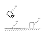
- FIG. 20 shows the positional relationship between the imaging device 201 and the rectangular parallelepiped 203 installed on the ground 202.
- the imaging device 201 exists in a state in which the vicinity of the ground can be imaged from a position having a certain height from the ground.
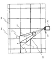
- FIG. 21 shows a captured image 301 acquired by the imaging device that captured the rectangular parallelepiped 203 in FIG.
- the grid line 303 is a square grid-like grid drawn on the ground 202.
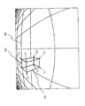
- FIG. 22 shows a bird's-eye view image 304 obtained by converting the captured image 301 of FIG. 21 by the viewpoint conversion process for projecting on the ground.
- the grid line 303 is converted into a grid line 306 composed of straight lines.
- the points of the rectangular parallelepiped 302 and the rectangular parallelepiped 305 are point A1 and point A2, point B1 and point B2, point C1 and point C2, point D1 and point D2, point E1 and point E2, point F1 and point F2, respectively.
- G1 and point G2, and point H1 and point H2 correspond to each other.
- This position 307 is on the vertical line where the imaging device 201 that acquired the captured image 301 that is the generation source of the overhead image 304 with respect to the position where the subject existing at the reference height in the overhead image 304 is reflected. Position.
- a vertical subject in the overhead image 304 is projected in the radial direction from the position of the imaging device 201.
- Such a reflection state is expressed as “falling” of the subject, and the radial direction is “falling direction”. It expresses.
- the position of the imaging device shown in the overhead image or the vehicle image in the drawings is synonymous with the position 307 of the imaging device 201 drawn on FIG.
- FIG. 24A shows the relationship between the imaging devices for two of Patent Document 2 and the area included in the overhead image generated from the image acquired by this imaging apparatus (display area of the overhead image).
- the imaging device 401 generates a bird's-eye view image that includes a region 403 and a region 405.
- the imaging device 402 generates a bird's-eye view image including a region 404 and a region 405. Therefore, the region 405 is a portion where a part of the overhead image is generated by overlapping a part of the captured images of both the imaging devices 401 and 402.
- the images are connected to each other using a joint in the area 405.
- a joint indicated by a dotted line 408 is arranged, a part of the overhead image generated from the image of the imaging device 401 is displayed on the region 406 side in the region 405, and on the region 407 side. A part of the overhead view image generated from the image of the imaging device 402 is displayed.
- FIG. 25A A rectangular parallelepiped 412 in FIG. 25A arranged at a position indicated by a dotted line 408 (see FIG. 24B) and FIG. 25B arranged at a position indicated by a dotted line 409 (see FIG. 24B).
- the display of is simply interrupted and disappears in the middle.
- FIG. 25 (A) and FIG. 25 (B) The difference between FIG. 25 (A) and FIG. 25 (B) is that the rectangular parallelepiped 412 in FIG. 25 (B) has a larger portion that is interrupted and disappears by the change in the arrangement location of the joint. .
- FIG. 25C in which the joint is arranged at the position indicated by the dotted line 410 (see FIG. 24B), the rectangular parallelepiped 412 is reflected on the region 406 side, and at the same time, the region straddling the joint. It is reflected on the 407 side in a discontinuous state.
- a composite bird's-eye view image in which one subject is separated into two and two subjects appear to be present may mislead the recognition of the state of the subject and the position with respect to the vehicle. There is.
- Patent Document 1 there is a possibility that the positional relationship on the reference height between the own vehicle and the overhead view image and between the adjacent overhead view images is shifted. Further, in Patent Document 2, there is a possibility that a subject such as a rectangular parallelepiped that extends in a direction perpendicular to the ground is interrupted across a joint and appears discontinuously.
- the present invention has been made in view of the above circumstances, and is an overhead image generation apparatus, an overhead image generation method, and an overhead image generation program capable of accurately recognizing the position and shape of a subject in a composite overhead image.
- the purpose is to provide.
- the bird's-eye view image generation device of the present invention has a captured image acquisition unit that acquires captured images captured by a plurality of imaging devices mounted on a vehicle, and an overhead view of the captured image acquired by the captured image acquisition unit by viewpoint conversion processing.
- the overhead image synthesis unit that synthesizes a plurality of overhead images converted by the image conversion unit, and the two overhead images corresponding to two imaging devices with overlapping imaging ranges, the overlap Within the imaging range, an arbitrary position on the periphery of the vehicle image corresponding to the vehicle included in the overhead view image is used as an end point, between the two radial directions from the two imaging devices toward the end point, and from the end point
- a joint setting unit that sets a line extending in an arbitrary direction opposite to the vehicle image as a joint that connects two overhead images synthesized by the overhead image synthesis unit; Equipped with a.
- the joint setting unit sets the joint along one of the two radial directions in the two overhead images.
- the vertical subject does not fall down in any direction across the joint within the range included in the overhead image of the imaging apparatus that is the reference for the direction of the line along the joint. Therefore, within this range, the display in the height direction of the subject is not interrupted and disappears in the middle, so that it is displayed larger and it is easy to recognize the presence of the subject.
- the joint setting unit may be configured such that, in the two bird's-eye view images, the first angle formed by the driver's line-of-sight direction and the first radiation direction is the line-of-sight.
- the angle is smaller than a second angle formed by the direction and the second radiation direction, the joint is set along a direction approaching the first radiation direction from the line-of-sight direction.
- an overhead image of an imaging device in which the vertical object tilt direction is close to the driver's line-of-sight direction is displayed, while an overhead image of an imaging device far from the driver's line-of-sight direction is an overhead image of the above-described nearby imaging device.
- the joint setting unit uses the corner of the vehicle image as the end point in the two overhead images.
- the direction of one side of the vehicle is such that one side of the vehicle image is in contact with a region included in only one bird's-eye view image generated from an imaging device whose position is closest to one side of the vehicle image. And the direction of the bird's-eye view image coincide with each other, and it becomes easier to recognize the direction in which the subject exists with the vehicle as the center.
- the overhead image generation apparatus of the present invention includes a vehicle information acquisition unit that acquires vehicle information of the vehicle, and the joint setting unit is based on the vehicle information acquired by the vehicle information acquisition unit. Set eyes.
- the position of the joint can be changed according to the application and the situation around the vehicle, and the state of the subject and the position of the subject relative to the vehicle can be easily recognized without misunderstanding.
- the vehicle information acquisition unit acquires the vehicle information including a traveling direction of the vehicle
- the joint setting unit includes a region on the traveling direction side of the vehicle, and the The seam is set avoiding a region near the direction opposite to the traveling direction in a direction orthogonal to the traveling direction.
- the overhead image generation apparatus of the present invention includes a synthesized overhead image synthesized by the overhead image synthesis unit, and a captured image acquired by the captured image acquisition unit or an overhead image converted by the image conversion unit.
- An image output unit that outputs simultaneously is provided.
- the driver can ensure the visibility and wide field of view of the three-dimensional object that is greatly deformed and difficult to recognize on the composite overhead image within one video, and the visibility is supplemented.
- the overhead image generation method of the present invention is an overhead image generation method of the overhead image generation device, the step of acquiring captured images captured by a plurality of imaging devices, and viewpoint conversion processing on the acquired captured images
- the step of converting to a bird's-eye view image, the step of synthesizing the converted plurality of bird's-eye view images, and the two bird's-eye view images corresponding to two imaging devices having overlapping imaging ranges An arbitrary position on the periphery of the vehicle image corresponding to the vehicle included in the bird's-eye view image is used as an end point, and between the two radial directions from the two imaging devices toward the end point, the opposite side from the vehicle image from the end point A line extending in an arbitrary direction is set as a joint connecting the two overhead images synthesized by the overhead image synthesis unit.
- the overhead image generation program of the present invention is a program for causing a computer to execute each step of the overhead image generation method.
- FIGS. 4A to 4C are diagrams showing an example of a synthesized portion of two adjacent overhead images among the synthesized overhead images according to the first embodiment of the present invention.
- FIGS. 4A to 4D are diagrams showing examples of radiation that passes through end points within an image-capable angle of view of the imaging apparatus according to the first embodiment of the present invention.
- A)-(C) The figure which shows an example of the synthetic
- A), (B) The figure which shows an example of the synthetic
- FIGS. 8A to 8D are diagrams showing examples of radiation (joints) passing through end points within an angle of view capable of being picked up by an image pickup apparatus according to a second embodiment of the present invention.
- (A) The figure which shows an example of the range between two radiations which go to an end point from an imaging device within the imaging range by two imaging devices which concern on the 3rd Embodiment of this invention
- (B) 3rd of this invention The figure which shows an example of the driver
- the block diagram which shows the structural example of the bird's-eye view image output system which concerns on the 5th Embodiment of this invention.
- (A) The figure which shows an example of the range between two radiations which go to an end point from an imaging device within the imaging range by two imaging devices which concern on the 5th Embodiment of this invention.
- the figure which shows an example of the output image of the bird's-eye view image generation apparatus which concerns on the 6th Embodiment of this invention (A) A diagram showing a relationship between a conventional vehicle, a subject, and a first reference height, (B) A diagram showing a relationship between a conventional vehicle, a subject, and a second reference height, (C) a conventional first The figure which shows the bird's-eye view image obtained from 1 reference
- the figure which shows the bird's-eye view image which converted the captured image of FIG. 21 by the viewpoint conversion process which projects on the ground The figure which shows that the line segment of the height direction of the rectangular parallelepiped of the bird's-eye view image of FIG. 22 crosses at a predetermined point.
- (A) The figure which shows the relationship between two conventional imaging devices and the display area containing the bird's-eye view image produced
- (B) Two conventional imaging devices, The figure which shows the relationship between the display area containing the bird's-eye view image produced
- (A)-(C) The figure which shows an example of the synthetic
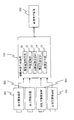
- FIG. 1 is a block diagram illustrating a configuration example of an overhead image output system according to the first embodiment of the present invention.
- the overhead image generation device 501 is mounted on a vehicle, for example, and performs various processes such as a process for generating an overhead image.
- the front imaging apparatus 502 images the front periphery of the vehicle.
- the rear imaging device 503 images the rear periphery of the vehicle.
- the right side imaging device 504 images the right side periphery of the vehicle.
- the left side imaging device 505 images the left side periphery of the vehicle.
- the image display device 506 is an in-vehicle monitor or the like installed in the vehicle that displays an input image or the like. These devices 501 to 506 are electrically connected.
- Each of the imaging devices 502 to 505 is mounted on a vehicle and generally has an angle of view of about 180 degrees.
- the overhead image generation device 501 is connected to the front imaging device 502, the rear imaging device 503, the right side imaging device 504, and the left side imaging device 505 on the input side, and on the output side, An image display device 506 is connected.
- a front imaging device 502, a rear imaging device 503, a right side imaging device 504, a left side imaging device 505, and an image display device 506 connected to the overhead image generation device 501 are an electronic control unit (not shown) installed in the vehicle. You may connect via ECU: Electric Control Unit.
- the overhead image generation device 501 includes a known CPU, ROM, RAM, and the like, and includes a captured image acquisition unit 51, an image conversion unit 52, an overhead image synthesis unit 53, a joint setting unit 54, and an image output unit 55. Configured.
- the functions of the captured image acquisition unit 51, the image conversion unit 52, the overhead image synthesis unit 53, the joint setting unit 54, and the image output unit 55 are, for example, programs stored in the ROM by the CPU in the overhead image generation device 501. It is realized by executing.
- the captured image acquisition unit 51 acquires a captured image that is an image captured by each of the imaging devices 502 to 505 via a wired or wireless line or cable.
- the image conversion unit 52 converts the captured image acquired by the captured image acquisition unit 51 into an overhead image by viewpoint conversion processing.
- a bird's-eye view image is an image drawn as if looking down at the ground from a high place.
- An example of the viewpoint conversion process is described in the following document. (Reference Patent Document) Japanese Patent Application Laid-Open No. 2004-289386
- the bird's-eye view image synthesis unit 53 synthesizes a plurality of bird's-eye images converted by the image conversion unit 52 to generate a synthesized bird's-eye view image. Also, the overhead image synthesis unit 53 connects a plurality of images at the joint set by the joint setting unit 54 to generate a composite overhead image.
- the joint setting unit 54 includes two overhead images (for example, reference numeral 707 in FIG. 3B) corresponding to two imaging apparatuses having overlapping imaging ranges (for example, reference numerals 503 and 505 in FIG. 3A). 708), the joint setting unit 54 within the above-described overlapping imaging range (for example, see reference numeral 705 in FIG. 3A), the vehicle image corresponding to the vehicle included in the overhead image (for example, FIG. 2).
- An arbitrary position on the periphery of (A) is an end point (for example, see reference numeral 702 in FIG. 3A). Between the two imaging directions from the two imaging devices to the end point (for example, refer to the directions of reference numerals 703 and 704 in FIG.
- the end point is in an arbitrary direction opposite to the vehicle image.
- the extending line is set as a joint that connects the two overhead images synthesized by the overhead image synthesis unit 53 (see, for example, reference numeral 706 in FIG. 3B). Note that the end points described in the present embodiment indicate end points closer to the joint imaging device. Details of the joint setting method by the joint setting unit 54 will be described later. For example, one joint is set for each two overhead images to be joined.
- the image output unit 55 outputs the combined overhead image generated by the overhead image synthesizing unit 53 and other images to the image display device 506 via a wired or wireless line or cable.
- the relationship between the positions and orientations of the imaging devices 502 to 505 and the vehicle 601 is as shown in FIG.
- the composite overhead image 603 displayed on the image display device 506 is as shown in FIG.
- the vehicle image 602 assumes a position where the vehicle 601 exists in the real world.
- the area of the vehicle image 602 is shown as a rectangular area, but the shape of this area is not limited to a rectangle.
- the synthesized bird's-eye view image 603 is obtained by subjecting the captured images of the imaging devices 502 to 505 to viewpoint conversion processing by the image conversion unit 52 so as to surround the entire periphery of the vehicle image 602, and the respective images are synthesized by the overhead view image synthesis unit 53. Is.
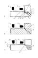
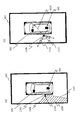
- FIGS. 3A to 3C are diagrams illustrating an example of a synthesized portion of two adjacent overhead images in the synthesized overhead image 603 (see FIG. 2B).
- reference numeral 701 denotes a range (overhead image display area) included in the overhead image generated from the captured image of the rear imaging device 503 or the left side imaging device 505.
- Reference numeral 702 indicates an end point closer to the joint imaging devices 503 and 505.
- Reference numeral 703 indicates radiation that passes through the end point 702 from the position of the rear imaging device 503.
- Reference numeral 704 indicates radiation that passes through the end point 702 from the position of the left side imaging device 505.
- Reference numeral 705 indicates a range surrounded by the display range 701, the radiation 703, and the radiation 704. This range is a range where the imaging range of the rear imaging device 503 and the imaging range of the left side imaging device 505 overlap.
- FIG. 3B a region 707 in which a part of the overhead image of the rear imaging device 503 is displayed when the joint 706 is arranged in an arbitrary radial direction from the end point 702 in the range 705, and the left side An area 708 in which a part of the overhead image of the imaging device 505 is displayed is shown.
- FIG. 3C is a diagram illustrating a state in which two overhead images are synthesized based on the joint 706, and vertical subjects 710 and 714 are reflected at positions 709 and 713 on the reference height, respectively. Note that the vertical subject in this embodiment is a subject perpendicular to the ground.
- the vertical subject 710 reflected at the position 709 falls in the direction of the radiation 711 passing from the rear imaging device 503 through the position 709 and the direction of the radiation 712 passing through the position 709 from the left side imaging device 505.
- the image display device 506 displays an image that has fallen in only one direction of the radiation 711 due to the positional relationship between the region 707 and the region 708.
- the vertical subject 714 reflected at the position 713 falls in the direction of the radiation 715 passing from the rear imaging device 503 through the position 713 and the direction of the radiation 716 passing through the position 713 from the left side imaging device 505.
- the image display device 506 displays an image that has fallen in only one direction of the radiation 716 depending on the positional relationship between the region 707 and the region 708.
- the display of the collapse is interrupted at the position of the intersection 717 between the joint 706 and the radiation 716.
- the joint 706 is arranged (set) in a direction between the radiation 703 and the radiation 704 (within the range 705) so as to be within the range 705.
- neither of the two radiations intersects the joint 706 in the outer direction of the two radiations from the two imaging devices 503 and 505.
- two radiations 711 and 712 (715 and 716) passing through the position of the subject 710 (714) from the positions of the two imaging devices 503 and 505 are connected in the outer direction in which the fall from the position of the subject 710 (714) occurs. Only one of the eyes 706 may intersect, but both do not intersect.
- FIG. 4A an area 719 in which a part of the overhead image of the rear imaging device 503 is displayed when the joint 718 is arranged in the radial direction from the end point 702 outside the range 705, and the left side An area 720 in which a part of the bird's-eye view image of the side imaging device 505 is displayed is shown.
- FIG. 4B shows a state in which two overhead images are synthesized based on the joint 718, and vertical subjects 710 and 714 appear at positions 709 and 713 on the same reference height as FIG. 3C, respectively.
- FIG. 3C the vertical subject 710 reflected at the position 709 is displayed that falls in only one direction of the radiation 711.
- the vertical subject 714 reflected at the position 713 is significantly different from FIG.
- the positional relationship between the region 719 and the region 720 what is displayed in the direction of the radiation 716 is interrupted at the intersection 721 between the joint 718 and the radiation 716.
- what is displayed falling down in the direction of the radiation 715 is interrupted at the position of the intersection 722 of the joint 718 and the radiation 715. Therefore, the subject 714 is displayed discontinuously.
- the joint 718 is arranged in a direction (outside the range 705) that is not between the radiation 703 and the radiation 704 extending from the end point 702 so as to be out of the range 705.
- both of the two radiations may intersect the joint 718 in the outer direction of the two radiations from the two imaging devices.
- both of the two radiations 715 and 716 are joints 718 in the outward direction in which the fall from the position of the subject 714 occurs. Interact with.
- the vertical subject 714 is discontinuously reflected across the joint.
- the bird's-eye view image generation device 501 has a captured image acquisition unit 51 that acquires captured images captured by the plurality of imaging devices 503 and 505, and a bird's-eye view of the acquired captured image by viewpoint conversion processing.
- An image conversion unit 52 that converts to an image
- an overhead image synthesis unit 53 that synthesizes a plurality of converted overhead images
- a joint setting unit 54 selects any of the peripheral edges of the vehicle image corresponding to the vehicle included in the overhead image within the overlapping imaging range in the two overhead images corresponding to the two imaging devices 503 and 505 whose imaging ranges overlap.
- the line is set as a joint 706 that connects the two overhead images synthesized by the overhead image synthesis unit 53.
- both the joint 706 and the two radiations 711 and 712 (715 and 716) do not intersect with each other, or only one intersects.
- the imaging range of the two imaging devices can be used regardless of the vehicle image 602. Seams may be arranged within the respective ranges such as the ranges 801 to 804 with an arbitrary position on the periphery of the vehicle image 602 as an end point.
- the configuration of the overhead image output system of the present embodiment is the same as the configuration of the overhead image output system of the first embodiment shown in FIG.
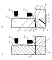
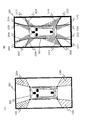
- FIGS. 6A to 6C and FIGS. 7A and 7B show an example of a synthesized portion of two adjacent overhead images in the synthesized overhead image 603 (see FIG. 2B). Yes.
- FIG. 6A shows a bird's-eye view image display range 701, end points 702, radiation 703, and radiation 704, as in FIG. 3A.
- a part of the overhead image of the rear imaging device 503 is displayed when the joint 901 is arranged so as to coincide with the direction of the radiation 703 in FIG. 6A, that is, along the radiation 703.
- the display area 902 to be displayed and the display area 903 in which a part of the overhead image of the left side imaging device 505 is displayed are shown.
- FIG. 6C is a diagram showing a state in which a bird's-eye view image is synthesized based on the joint 901 in FIG. 6B, and vertical subjects 905 and 909 are reflected at positions 904 and 908 on the reference height, respectively. is there.
- the vertical subject 905 reflected in the position 904 falls in the direction of the radiation 906 passing from the rear imaging device 503 through the position 904 and the direction of the radiation 907 passing through the position 904 from the left side imaging device 505.
- the image display device 506 displays an image that has fallen in only one direction of the radiation 906 due to the positional relationship between the display area 902 and the display area 903.
- the joint 901 is disposed along the direction of the radiation 703 from the position of the rear imaging device 503. For this reason, the vertical subject 905 displayed by falling in the direction of the radiation 906 passing through the position 904 that is not in the direction of the radiation 703 from the position of the rear imaging device 503 does not intersect the joint 901.
- the vertical subject 909 reflected at the position 908 falls in the direction of the radiation 910 passing from the rear imaging device 503 to the position 908 and the direction of the radiation 911 passing from the left side imaging device 505 to the position 908.
- the image display device 506 displays an image that falls down in only one direction of the radiation 910 due to the positional relationship between the display area 902 and the display area 903.
- the joint 901 is disposed along the direction of the radiation 703 from the position of the rear imaging device 503. Therefore, as with the vertical subject 905, the vertical subject 909 that falls down and is displayed in the direction of the radiation 910 passing through the position 908 that is not in the direction of the radiation 703 from the position of the rear imaging device 503 does not intersect the joint 901.
- FIG. 7A illustrates a display area 913 in which a part of the overhead image of the rear imaging device 503 is displayed in the range 705 when the joint 912 is disposed so as not to coincide with both the radiations 703 and 704.
- FIG. 7B a bird's-eye view image is synthesized based on the joint 912 in FIG. 7A, and vertical subjects 905 and 909 are respectively displayed at the same reference height positions 904 and 908 as in FIG. 6C. It shows a state of being crowded.
- the vertical subject 905 reflected at the position 904 is displayed that has fallen in only one direction of the radiation 906, but the position of the intersection 915 between the joint 912 and the radiation 906 is displayed. Is interrupted. At this time, the vertical subject 905 displayed by falling in the direction of the radiation 906 from the position of the rear imaging device 503 intersects with the joint 912.
- the vertical subject 909 reflected at the position 908 falls in the direction of the radiation 910 passing from the rear imaging device 503 to the position 908 and the direction of the radiation 911 passing from the left side imaging device 505 to the position 908.
- the image display device 506 displays an image that has fallen in only one direction of the radiation 911 due to the positional relationship between the display area 913 and the display area 914.
- the vertical subject 909 does not intersect with the joint 912, but since the radiation 911 and the joint 912 are not parallel, they intersect outside the display areas 913 and 914 (see FIG. 7A).
- the direction in which the joint 912 extends does not coincide with the direction of the radiation 906 from the position of the rear imaging device 503.
- the position of the rear imaging device 503 is a position that is a base point in the tilting direction of the vertical subject 905 in the display area 913. Therefore, depending on the position of the subject 905, the fall may occur in a direction across the joint 912. In this case, the vertical subject 905 is interrupted and disappears in the middle of the range included in the overhead image.
- the joint setting unit 54 joins the two bird's-eye view images along one of the two radiation directions 703 and 704 (radiation direction).
- the eye 901 is set.
- the vertical subject falls down at any position within the range included in the bird's-eye view image of the rear imaging device 503 that is the reference of the direction of the radiation 703 with which the joint 901 is matched (aligned). It does not occur in the direction across 901.
- the display of the subject is displayed in a large size without being interrupted and disappearing. Therefore, it becomes easy to recognize the presence of the subject.
- the image capturing range of the two image capturing apparatuses can be used regardless of the vehicle image 602. Seams may be arranged along the directions of the radiations 1001 to 1004 with any position on the periphery of the vehicle image 602 as an end point.
- FIGS. 9A and 9B and FIGS. 10A and 10B are diagrams illustrating an example of the synthesized overhead image 603.
- FIG. 9A the relationship between the radiation 1102 indicating the line-of-sight direction from the position of the driver 1101 and the radiation dotted line 1103 indicating the fall-down direction when a vertical subject appears in the overhead image of the rear imaging device 503. Is shown.
- FIG. 9B a radiation 1102 indicating the direction of the line of sight from the position of the driver 1101, and a radiating dotted line 1104 indicating the direction of the fall when a vertical subject appears in the overhead view image of the left side imaging device 505, , Showing the relationship.
- the end point 1105 closer to the joint imaging device is arranged.
- a vertical subject exists at the point 1109 a condition for arranging a joint from the end point 1105 in an arbitrary radial direction will be considered.
- the line-of-sight direction and the tilt-down direction are close means that the angle formed by the line-of-sight direction and the tilt-down direction is smaller, and that the line-of-sight direction and the tilt-down direction are far away. Means that the angle formed by the line-of-sight direction and the tilt-down direction is larger.
- the joint setting unit 54 uses the two bird's-eye view images in the line-of-sight direction 1110 of the vehicle driver 1101 and the direction of the radiation 1107 (first emission direction). Is smaller than the second angle formed by the line-of-sight direction 1110 and the direction of the radiation 1106 (second radiation direction), the lines are connected along the direction close to the radiation 1107 from the line-of-sight direction 1110. Set eyes.
- the bird's-eye view image side where the vertical subject's tilting direction is close to the driver's line-of-sight direction is displayed, and the bird's-eye view image side far from the driver's line-of-sight direction is not displayed.
- the bird's-eye view image side far from the driver's line-of-sight direction is not displayed.
- only a bird's-eye view image in which the line-of-sight direction 1110 when the driver 1101 looks at the vertical subject from the driver's seat and the direction in which the subject falls down is displayed. Therefore, it becomes easy to recognize the direction in which the subject exists with the driver as the center.
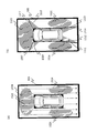
- FIGS. 11A to 11C are diagrams illustrating an example of a part of the composite overhead image 603 (see FIG. 2B).
- each end point 1201 closer to the joint imaging device is located on each side representing the left end and the right end of the vehicle image 602, and a joint 1202 extending from each end point 1201 is shown.
- the left end and the right end do not include a corner portion.
- the height direction is relatively close to the vehicle, that is, the height of the rear imaging device 503 is the same as the height of the vehicle. Further, it is assumed that the rear imaging device 503 is located as close to the rear end as possible at the center of the left and right sides of the vehicle. Further, it is assumed that the vehicle is mounted on the vehicle in a general layout arrangement in which the vehicle and the ground are reflected (the vehicle and the ground are included in the imaging range of the rear imaging device 503).
- a vehicle having a height from a reference height is projected onto the overhead image of the rear imaging device 503, so that when viewed vertically downward from above the vehicle (virtual viewpoint of the overhead image), a vehicle that reflects the rear imaging device 503 and The rear direction of the vehicle with a short distance is hardly deviated.
- the vehicle left-right direction in which the distance between the rear imaging device 503 and the reflected vehicle is long deviates greatly, and the vehicle is reflected in the region 1203.
- each end point 1204 closer to the joint imaging device is located on the side representing the rear end of the vehicle image 602, and a joint 1205 extending from each end point 1204 is shown.
- the left-side imaging device 505 and the right-side imaging device 504 are relatively close in height to the vehicle, that is, the left-side imaging device 505 or the right-side imaging device 504 has the same height as the vehicle.
- the left side imaging device 505 and the right side imaging device 504 are located on the left end side or the right end side of the vehicle as much as possible.
- the vehicle is mounted on the vehicle in a general layout arrangement in which the vehicle and the ground are reflected (the vehicle and the ground are included in the imaging range of the left side imaging device 505 or the right side imaging device 504).
- the position on the overhead view image is shifted.
- the vehicle upper side virtual viewpoint of the bird's-eye view image
- the left-right direction of the vehicle in which the distance between the left-side imaging device 505 or the right-side imaging device 504 and the reflected vehicle is short is hardly shifted.
- the vehicle front-rear direction in which the distance between the left-side imaging device 505 or the right-side imaging device 504 and the reflected vehicle is long deviates greatly, and the vehicle is reflected in the region 1206 or the region 1207.
- the end point 1208 of the joint 1209 for synthesizing the bird's-eye view image of the rear imaging device 503 and the left side imaging device 505 is arranged so as to be positioned at the corner of the side of the vehicle image 602. Show things.
- the vehicle on the bird's-eye view image generated from the captured image of the left-side imaging device 505 or the right-side imaging device 504 that is shifted and displayed is not displayed.
- FIGS. 11A and 11B when the end point closer to the joint imaging device is shifted from the corner of the side of the vehicle image 602, one rear end or side end of the vehicle image 602 is disposed.
- the two overhead-view image display areas are in contact with the side that represents, and when viewed vertically downward from above the vehicle, there is a possibility that a vehicle that appears greatly deviated from the actual position is displayed.
- the above end points are arranged at the corners of the sides of the vehicle image 602 as in the example of FIG. 11C, one bird's-eye view image display area is provided for one rear end or side end of the vehicle image 602. It is difficult to display a vehicle that touches and appears greatly shifted.
- rear end of the vehicle here corresponds to the rear end (lower end) of the vehicle image 602 in FIGS. 11A to 11C.
- side end of the vehicle here corresponds to the side end (left end or right end) of the vehicle image 602 in FIGS. 11 (A) to (C).
- the joint 1301 is arranged with the corner 1302 of the side of the vehicle image 602 as an end point closer to the imaging device of the joint 1301.
- the joint 1303 is arranged with the corner 1304 of the side of the vehicle image 602 as an end point closer to the imaging device of the joint 1303.
- the joint 1305 is arranged with the corner 1306 of the side of the vehicle image 602 as an end point closer to the imaging device of the joint 1305.
- the joint 1307 is arranged with the corner 1308 of the side of the vehicle image 602 as an end point closer to the imaging device of the joint 1307.
- the entire side 1309 representing the front end of the vehicle image 602 is in contact with the entire one side representing a part of the periphery of the display area 1310 on which a part of the overhead image of the front imaging device 502 is displayed.
- the entire side 1311 representing the left end of the vehicle image 602 is in contact with the entire one side representing a part of the periphery of the display area 1312 on which a part of the overhead image of the left side imaging device 505 is displayed.
- the entire side 1313 representing the rear end of the vehicle image 602 is in contact with the entire one side representing a part of the periphery of the display area 1314 on which a part of the overhead image of the rear imaging device 503 is displayed.
- the entire side 1315 representing the right end of the vehicle image 602 is in contact with the entire one side representing a part of the periphery of the display area 1316 on which a part of the overhead image of the right-side imaging device 504 is displayed.
- the end point closer to the joint imaging device is set to each corner of the side of the vehicle image 602 (the side of the display area in which a part of two overhead images adjacent to each other to be combined is displayed)
- the combined overhead image 603 is generated at all the corners
- a display area where a part of one overhead image is displayed is in contact with one side of the vehicle image 602. Therefore, the directionality of each side of the vehicle image 602 and each bird's-eye view image with respect to the vehicle matches.
- the joint on the synthesized overhead image 603 displayed by the image display device 506 has a predetermined width so that the driver can clearly recognize the break of the overhead image.
- the joint setting unit 54 uses the corners of the vehicle image 602 as end points in the two bird's-eye view images.
- a corner where two sides close to the imaging device intersect in the display area in which a part of the two overhead images is displayed is an end point of the joint
- a single bird's-eye view image display area generated from an imaging device whose position is closest to one side of the vehicle image 602 is in contact with one side.
- FIG. 13 is a block diagram illustrating a configuration example of an overhead image output system according to the fifth embodiment of the present invention.
- the overhead image generation device 1401 is mounted on a vehicle, for example, and performs various processes such as a process for generating an overhead image.
- the steering wheel horn angle detection device 1402 detects a straight traveling state, a left turn state, a right turn state, or a rotation angle of the steering wheel of the vehicle, and outputs it to the overhead view image generation device 1401.
- the traveling state detection device 1403 detects information such as whether the vehicle is moving forward or backward, and outputs the detected information to the overhead image generation device 1401.
- the driver operation reception device 1404 receives information input by the driver through an input device (not shown) installed in the vehicle and outputs the information to the overhead image generation device 1401.
- the obstacle detection device 1405 detects an obstacle from a captured image acquired by a sonar or an imaging device mounted on the vehicle, and outputs the information to the overhead image generation device 1401. These devices are electrically connected.
- the overhead image generation device 1401 includes, on the input side, a front imaging device 502, a rear imaging device 503, a right side imaging device 504, a left side imaging device 505, a handle snake angle detection device 1402, a traveling state.
- a detection device 1403, a driver operation reception device 1404, and an obstacle detection device 1405 are connected, and an image display device 506 is connected to the output side.
- the bird's-eye view image generation device 1401 is a vehicle information acquisition unit 56 that acquires vehicle information of a vehicle on which the bird's-eye view image generation device 1401 is mounted in addition to the components that realize the functions of the bird's-eye view image generation device 501 described in FIG. Is provided.
- the vehicle information acquisition unit 56 receives various vehicle information from the steering wheel horn detection device 1402, the traveling state detection device 1403, the driver operation reception device 1404, and the obstacle detection device 1405 via a wired or wireless line or cable. get.
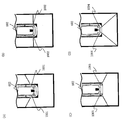
- FIGS. 14 (A) to (B), FIGS. 15 (A) to (B), FIGS. 16 (A) to (B), and FIG. 17 are synthesized overhead images 603 (see FIG. 6 (B)). It is a figure which shows an example.
- each corner of the vehicle image 602 is set as an end point closer to the joint imaging device, and each joint can be located when the joint is arranged along an arbitrary radial direction.
- ⁇ 1504 are shown.
- the vehicle snake angle detection device 1402 obtain various vehicle information as described above in real time. can do.
- the joint setting unit 54 can be switched to an optimum position within the range 1501 to 1504 in accordance with the application and the situation around the vehicle.
- FIG. 14B shows a case where a joint is arranged at a position that is a boundary (one of the sides that are the periphery of the range 1501) in the ranges 1501 to 1504. There are two joints for each corner of the vehicle image 602.
- a vertical subject is reflected at the reference height position of each region.
- the display in the height direction of the subject may be interrupted and disappear due to the action.
- the background flows in the direction of the arrow 1523 (downward in the figure) on the composite overhead image 603 as shown in FIG. Therefore, priority is given to the area 1524 so that a vertical subject is not interrupted and disappears within the overhead image display range.
- they are arranged at the positions of joints 1507, 1511, 1513, and 1517, and the vertical subject falls down in the direction across the joints 1507, 1511, 1513, and 1517.
- the region may not overlap the region 1524.
- the joints 1531 to 1534 may not be symmetrical as shown in FIG.
- the overhead image generation device 501 of the present embodiment includes the vehicle information acquisition unit 56 that acquires vehicle information of a vehicle on which the overhead image generation device 501 is mounted.
- the joint setting unit 54 sets a joint based on the acquired vehicle information.
- the joint is changed according to the vehicle information between the two radiation directions from the position of the imaging device toward the end point.
- joints are set by avoiding regions on the vehicle traveling direction side (for example, the rear side when reversing) and regions that are opposite to the traveling direction in the direction orthogonal to the traveling direction (for example, the front side when moving backward). To do. Thereby, a seam can be switched to an optimal state according to a use or the situation around vehicles. Therefore, it becomes easy to recognize the state of the subject and the position with respect to the vehicle without misunderstanding.
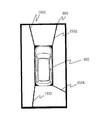
- FIG. 18 is a diagram illustrating an example of an output image of the overhead image generation device 1401.
- a combined overhead image 603 and a viewpoint conversion image different from the combined overhead image 603 are output simultaneously.
- the viewpoint conversion image may be at least part of the overhead image, may be at least part of the captured image captured by the imaging device, or may be another image.
- the composite overhead image 603 is arranged on the right side, and the viewpoint conversion image of the left side of the vehicle in which the vehicle 1602 is reflected is arranged on the left side.
- the output image 1601 is output to the image display device 506 by the image output unit 55 provided in the overhead image generation device 1401.
- the image display device 506 displays a plurality of images included in the output image at the same time.
- each image in the output image 1601 may be changed in consideration of the use of the image that is output simultaneously with the synthesized overhead image, the directionality of the output image with respect to the vehicle (which part is the image), and the like.
- the overhead image generation apparatus 501 of the present embodiment includes the synthesized overhead image (first image) synthesized by the overhead image synthesis unit 53 and the captured image or image conversion acquired by the captured image acquisition unit 51.
- the image output part 55 which outputs simultaneously the bird's-eye view image (2nd image) converted by the part 52 is provided.
- the synthesized overhead image and the second image that displays a different view from the synthesized overhead image or a portion that is not displayed on the synthesized overhead image may be output simultaneously.
- the present invention is useful for an overhead image generation apparatus, an overhead image generation method, an overhead image generation program, and the like that can recognize the position and shape of a subject in a synthesized overhead image with high accuracy.
- First reference height 102 Second reference height 103, 104, 105 Subject 201 Imaging device 202 Ground 203 Rectangular body 301 Imaging device 302, 305 Rectangular body 303, 306 Grid line 304 Overhead image 307 Position 401, 402 Imaging device 403, 404 , 405, 406, 407 Regions 408, 409, 410 Dotted line 411 Point 412 Rectangular body 501 Overhead image generation device 502 Front imaging device 503 Rear imaging device 504 Right side imaging device 505 Left side imaging device 506 Image display device 51 Captured image acquisition unit 52 Image conversion unit 53 Overhead image synthesis unit 54 Joint setting unit 55 Image output unit 56 Vehicle information acquisition unit 601 Vehicle 602 Vehicle image 603 Composite overhead view image 701 Overhead image display range 702 Endpoints 703 and 704 Pass the endpoint from the position of the imaging device Radiation 705 Display range Areas 706, 718 surrounded by 701, radiation 703, and radiation 704 Joints 707, 708, 719, 720 Regions 709, 713 Positions 710, 7
Landscapes
- Engineering & Computer Science (AREA)
- Multimedia (AREA)
- Physics & Mathematics (AREA)
- General Physics & Mathematics (AREA)
- Theoretical Computer Science (AREA)
- Mechanical Engineering (AREA)
- Image Processing (AREA)
- Closed-Circuit Television Systems (AREA)
Abstract
L'invention concerne un dispositif de génération d'image de vue d'œil d'oiseau qui comporte une unité d'acquisition d'image capturée, une unité de conversion d'image, une unité de synthèse d'image de vue d'œil d'oiseau et une unité de réglage de joint. En ce qui concerne deux images de vue d'œil d'oiseau correspondant à deux dispositifs d'imagerie dont les plages d'image se chevauchent, l'unité de réglage de joint règle une position donnée dans la périphérie d'une image de véhicule correspondant au véhicule contenu dans les images de vue d'œil d'oiseau à l'intérieur des plages d'imagerie se chevauchant en tant que point de bord, et règle une ligne s'étendant du point de bord dans une direction donnée sur le côté opposé de l'image de véhicule entre deux directions radiales s'étendant des deux dispositifs d'imagerie au point de bord en tant que joint pour assembler les deux images de vue d'œil d'oiseau à synthétiser.
Priority Applications (4)
| Application Number | Priority Date | Filing Date | Title |
|---|---|---|---|
| CN201280016788.4A CN103477634B (zh) | 2011-09-30 | 2012-09-14 | 俯瞰图像生成装置和俯瞰图像生成方法 |
| EP12834713.5A EP2763406A4 (fr) | 2011-09-30 | 2012-09-14 | Dispositif de génération d'image de vue d'oeil d'oiseau, procédé de génération d'image de vue d'oeil d'oiseau et programme de génération d'image de vue d'oeil d'oiseau |
| JP2013535874A JP5962927B2 (ja) | 2011-09-30 | 2012-09-14 | 俯瞰画像生成装置、俯瞰画像生成方法、および俯瞰画像生成プログラム |
| US14/015,735 US9715631B2 (en) | 2011-09-30 | 2013-08-30 | Birds-eye-view image generation device, and birds-eye-view image generation method |
Applications Claiming Priority (2)
| Application Number | Priority Date | Filing Date | Title |
|---|---|---|---|
| JP2011217954 | 2011-09-30 | ||
| JP2011-217954 | 2011-09-30 |
Related Child Applications (1)
| Application Number | Title | Priority Date | Filing Date |
|---|---|---|---|
| US14/015,735 Continuation US9715631B2 (en) | 2011-09-30 | 2013-08-30 | Birds-eye-view image generation device, and birds-eye-view image generation method |
Publications (1)
| Publication Number | Publication Date |
|---|---|
| WO2013046593A1 true WO2013046593A1 (fr) | 2013-04-04 |
Family
ID=47994679
Family Applications (1)
| Application Number | Title | Priority Date | Filing Date |
|---|---|---|---|
| PCT/JP2012/005923 WO2013046593A1 (fr) | 2011-09-30 | 2012-09-14 | Dispositif de génération d'image de vue d'œil d'oiseau, procédé de génération d'image de vue d'œil d'oiseau et programme de génération d'image de vue d'œil d'oiseau |
Country Status (5)
| Country | Link |
|---|---|
| US (1) | US9715631B2 (fr) |
| EP (1) | EP2763406A4 (fr) |
| JP (1) | JP5962927B2 (fr) |
| CN (1) | CN103477634B (fr) |
| WO (1) | WO2013046593A1 (fr) |
Families Citing this family (16)
| Publication number | Priority date | Publication date | Assignee | Title |
|---|---|---|---|---|
| CN104469135B (zh) * | 2013-09-18 | 2017-11-28 | 株式会社理光 | 图像处理系统 |
| JP5971223B2 (ja) * | 2013-10-16 | 2016-08-17 | 株式会社デンソー | 合成画像生成装置 |
| JP6375633B2 (ja) * | 2014-02-12 | 2018-08-22 | 株式会社デンソー | 車両周辺画像表示装置、車両周辺画像表示方法 |
| US10336462B2 (en) | 2015-03-12 | 2019-07-02 | Vu Systems, LLC | Vehicle navigation methods, systems and computer program products |
| US20160300372A1 (en) * | 2015-04-09 | 2016-10-13 | Bendix Commercial Vehicle Systems Llc | System and Method for Graphically Indicating an Object in an Image |
| CN104967826A (zh) * | 2015-07-03 | 2015-10-07 | 上海弼智仿生高科技有限公司 | 固定区域监视系统及方法 |
| GB2556797B (en) * | 2015-11-06 | 2018-10-24 | Mitsubishi Electric Corp | Image processing apparatus, image processing method, and image processing program |
| JP6477444B2 (ja) * | 2015-11-25 | 2019-03-06 | 株式会社デンソー | 表示制御装置及び表示制御プログラム |
| JP6730606B2 (ja) * | 2016-11-25 | 2020-07-29 | 株式会社Jvcケンウッド | 俯瞰映像生成装置、俯瞰映像生成システム、俯瞰映像生成方法およびプログラム |
| KR102551099B1 (ko) | 2017-01-13 | 2023-07-05 | 엘지이노텍 주식회사 | 어라운드뷰 제공장치, 제공방법 및 이를 구비한 차량 |
| US10436485B2 (en) * | 2017-11-14 | 2019-10-08 | Haier Us Appliance Solutions, Inc. | Sealed system for a packaged terminal air conditioner unit |
| JP2019151304A (ja) * | 2018-03-06 | 2019-09-12 | アイシン精機株式会社 | 周辺監視装置 |
| GB2586712B (en) * | 2018-03-28 | 2021-12-22 | Mitsubishi Electric Corp | Image processing device, image processing method, and image processing program |
| US10967792B1 (en) * | 2018-10-12 | 2021-04-06 | Roger Stafford | Apparatus for monitoring periphery of a vehicle and displaying a view of the periphery on a display device |
| CN111402132B (zh) * | 2020-03-11 | 2024-02-02 | 黑芝麻智能科技(上海)有限公司 | 倒车辅助方法及系统、图像处理器及相应的辅助驾驶系统 |
| JPWO2021186853A1 (fr) * | 2020-03-19 | 2021-09-23 |
Citations (6)
| Publication number | Priority date | Publication date | Assignee | Title |
|---|---|---|---|---|
| JP2002027448A (ja) * | 2000-04-28 | 2002-01-25 | Matsushita Electric Ind Co Ltd | 画像処理装置および監視システム |
| JP2004289386A (ja) | 2003-03-20 | 2004-10-14 | Clarion Co Ltd | 画像表示方法、画像表示装置及び画像処理装置 |
| JP2007036668A (ja) * | 2005-07-27 | 2007-02-08 | Nissan Motor Co Ltd | 俯瞰画像表示システム及び俯瞰画像の表示方法 |
| JP2007041791A (ja) | 2005-08-02 | 2007-02-15 | Nissan Motor Co Ltd | 俯瞰画像表示システム及び俯瞰画像の表示方法 |
| JP2008033901A (ja) * | 2006-07-06 | 2008-02-14 | Nissan Motor Co Ltd | 車両用画像表示システム |
| JP2010200240A (ja) | 2009-02-27 | 2010-09-09 | Hyundai Motor Co Ltd | 車両周囲俯瞰画像表示装置及び方法 |
Family Cites Families (6)
| Publication number | Priority date | Publication date | Assignee | Title |
|---|---|---|---|---|
| EP1150252B1 (fr) | 2000-04-28 | 2018-08-15 | Panasonic Intellectual Property Management Co., Ltd. | Synthèse d'une image à partir d'une multitude de vues de caméra |
| JP4639753B2 (ja) * | 2004-10-25 | 2011-02-23 | 日産自動車株式会社 | 運転支援装置 |
| US20090128630A1 (en) | 2006-07-06 | 2009-05-21 | Nissan Motor Co., Ltd. | Vehicle image display system and image display method |
| JP5182042B2 (ja) * | 2008-11-28 | 2013-04-10 | 富士通株式会社 | 画像処理装置、画像処理方法及びコンピュータプログラム |
| JP5503660B2 (ja) * | 2009-09-24 | 2014-05-28 | パナソニック株式会社 | 運転支援表示装置 |
| JP5548002B2 (ja) * | 2010-03-25 | 2014-07-16 | 富士通テン株式会社 | 画像生成装置、画像表示システム及び画像生成方法 |
-
2012
- 2012-09-14 WO PCT/JP2012/005923 patent/WO2013046593A1/fr active Application Filing
- 2012-09-14 CN CN201280016788.4A patent/CN103477634B/zh active Active
- 2012-09-14 EP EP12834713.5A patent/EP2763406A4/fr not_active Withdrawn
- 2012-09-14 JP JP2013535874A patent/JP5962927B2/ja active Active
-
2013
- 2013-08-30 US US14/015,735 patent/US9715631B2/en active Active
Patent Citations (6)
| Publication number | Priority date | Publication date | Assignee | Title |
|---|---|---|---|---|
| JP2002027448A (ja) * | 2000-04-28 | 2002-01-25 | Matsushita Electric Ind Co Ltd | 画像処理装置および監視システム |
| JP2004289386A (ja) | 2003-03-20 | 2004-10-14 | Clarion Co Ltd | 画像表示方法、画像表示装置及び画像処理装置 |
| JP2007036668A (ja) * | 2005-07-27 | 2007-02-08 | Nissan Motor Co Ltd | 俯瞰画像表示システム及び俯瞰画像の表示方法 |
| JP2007041791A (ja) | 2005-08-02 | 2007-02-15 | Nissan Motor Co Ltd | 俯瞰画像表示システム及び俯瞰画像の表示方法 |
| JP2008033901A (ja) * | 2006-07-06 | 2008-02-14 | Nissan Motor Co Ltd | 車両用画像表示システム |
| JP2010200240A (ja) | 2009-02-27 | 2010-09-09 | Hyundai Motor Co Ltd | 車両周囲俯瞰画像表示装置及び方法 |
Non-Patent Citations (1)
| Title |
|---|
| See also references of EP2763406A4 |
Also Published As
| Publication number | Publication date |
|---|---|
| US20140002660A1 (en) | 2014-01-02 |
| CN103477634B (zh) | 2016-11-23 |
| EP2763406A4 (fr) | 2015-06-17 |
| JP5962927B2 (ja) | 2016-08-03 |
| US9715631B2 (en) | 2017-07-25 |
| EP2763406A1 (fr) | 2014-08-06 |
| CN103477634A (zh) | 2013-12-25 |
| JPWO2013046593A1 (ja) | 2015-03-26 |
Similar Documents
| Publication | Publication Date | Title |
|---|---|---|
| JP5962927B2 (ja) | 俯瞰画像生成装置、俯瞰画像生成方法、および俯瞰画像生成プログラム | |
| JP5068779B2 (ja) | 車両周囲俯瞰画像表示装置及び方法 | |
| JP4760831B2 (ja) | 車両周囲監視装置及び車両周囲監視方法 | |
| JP3894322B2 (ja) | 車両用視界モニタシステム | |
| JP4248570B2 (ja) | 画像処理装置並びに視界支援装置及び方法 | |
| JP4315968B2 (ja) | 画像処理装置並びに視界支援装置及び方法 | |
| JP6379779B2 (ja) | 車両用表示装置 | |
| JP7283059B2 (ja) | 周辺監視装置 | |
| JP5724446B2 (ja) | 車両の運転支援装置 | |
| JP2013501280A (ja) | 車両周辺のモニタ方法 | |
| JP5451497B2 (ja) | 運転支援表示装置 | |
| JP5966513B2 (ja) | 車両の後側方撮影装置 | |
| US9162621B2 (en) | Parking support apparatus | |
| WO2017038123A1 (fr) | Dispositif de surveillance d'une zone entourant un véhicule | |
| EP3967554B1 (fr) | Système d'affichage pour véhicule | |
| JP2018063294A (ja) | 表示制御装置 | |
| WO2011013813A1 (fr) | Dispositif embarqué à bord dun véhicule et programme de traitement dimage | |
| JP2016213708A (ja) | 車両用表示装置 | |
| JP2006224927A (ja) | 車両周辺視認装置 | |
| JP5212422B2 (ja) | 運転支援装置 | |
| JP6724821B2 (ja) | 俯瞰映像生成装置、俯瞰映像生成システム、俯瞰映像生成方法およびプログラム | |
| JP2007028443A (ja) | 画像表示システム | |
| EP3967553A1 (fr) | Système d'affichage pour véhicule | |
| JP5091882B2 (ja) | 画像処理装置並びに視界支援装置及び方法 | |
| JP2007028444A (ja) | 画像表示システム |
Legal Events
| Date | Code | Title | Description |
|---|---|---|---|
| 121 | Ep: the epo has been informed by wipo that ep was designated in this application |
Ref document number: 12834713 Country of ref document: EP Kind code of ref document: A1 |
|
| ENP | Entry into the national phase |
Ref document number: 2013535874 Country of ref document: JP Kind code of ref document: A |
|
| WWE | Wipo information: entry into national phase |
Ref document number: 2012834713 Country of ref document: EP |
|
| NENP | Non-entry into the national phase |
Ref country code: DE |