WO2013046312A1 - 車両および車両の制御方法 - Google Patents
車両および車両の制御方法 Download PDFInfo
- Publication number
- WO2013046312A1 WO2013046312A1 PCT/JP2011/071977 JP2011071977W WO2013046312A1 WO 2013046312 A1 WO2013046312 A1 WO 2013046312A1 JP 2011071977 W JP2011071977 W JP 2011071977W WO 2013046312 A1 WO2013046312 A1 WO 2013046312A1
- Authority
- WO
- WIPO (PCT)
- Prior art keywords
- driving force
- vehicle
- driving
- state
- engine
- Prior art date
Links
Images


Classifications
-
- B—PERFORMING OPERATIONS; TRANSPORTING
- B60—VEHICLES IN GENERAL
- B60K—ARRANGEMENT OR MOUNTING OF PROPULSION UNITS OR OF TRANSMISSIONS IN VEHICLES; ARRANGEMENT OR MOUNTING OF PLURAL DIVERSE PRIME-MOVERS IN VEHICLES; AUXILIARY DRIVES FOR VEHICLES; INSTRUMENTATION OR DASHBOARDS FOR VEHICLES; ARRANGEMENTS IN CONNECTION WITH COOLING, AIR INTAKE, GAS EXHAUST OR FUEL SUPPLY OF PROPULSION UNITS IN VEHICLES
- B60K6/00—Arrangement or mounting of plural diverse prime-movers for mutual or common propulsion, e.g. hybrid propulsion systems comprising electric motors and internal combustion engines ; Control systems therefor, i.e. systems controlling two or more prime movers, or controlling one of these prime movers and any of the transmission, drive or drive units Informative references: mechanical gearings with secondary electric drive F16H3/72; arrangements for handling mechanical energy structurally associated with the dynamo-electric machine H02K7/00; machines comprising structurally interrelated motor and generator parts H02K51/00; dynamo-electric machines not otherwise provided for in H02K see H02K99/00
- B60K6/20—Arrangement or mounting of plural diverse prime-movers for mutual or common propulsion, e.g. hybrid propulsion systems comprising electric motors and internal combustion engines ; Control systems therefor, i.e. systems controlling two or more prime movers, or controlling one of these prime movers and any of the transmission, drive or drive units Informative references: mechanical gearings with secondary electric drive F16H3/72; arrangements for handling mechanical energy structurally associated with the dynamo-electric machine H02K7/00; machines comprising structurally interrelated motor and generator parts H02K51/00; dynamo-electric machines not otherwise provided for in H02K see H02K99/00 the prime-movers consisting of electric motors and internal combustion engines, e.g. HEVs
- B60K6/42—Arrangement or mounting of plural diverse prime-movers for mutual or common propulsion, e.g. hybrid propulsion systems comprising electric motors and internal combustion engines ; Control systems therefor, i.e. systems controlling two or more prime movers, or controlling one of these prime movers and any of the transmission, drive or drive units Informative references: mechanical gearings with secondary electric drive F16H3/72; arrangements for handling mechanical energy structurally associated with the dynamo-electric machine H02K7/00; machines comprising structurally interrelated motor and generator parts H02K51/00; dynamo-electric machines not otherwise provided for in H02K see H02K99/00 the prime-movers consisting of electric motors and internal combustion engines, e.g. HEVs characterised by the architecture of the hybrid electric vehicle
- B60K6/44—Series-parallel type
- B60K6/445—Differential gearing distribution type
-
- B—PERFORMING OPERATIONS; TRANSPORTING
- B60—VEHICLES IN GENERAL
- B60W—CONJOINT CONTROL OF VEHICLE SUB-UNITS OF DIFFERENT TYPE OR DIFFERENT FUNCTION; CONTROL SYSTEMS SPECIALLY ADAPTED FOR HYBRID VEHICLES; ROAD VEHICLE DRIVE CONTROL SYSTEMS FOR PURPOSES NOT RELATED TO THE CONTROL OF A PARTICULAR SUB-UNIT
- B60W20/00—Control systems specially adapted for hybrid vehicles
- B60W20/10—Controlling the power contribution of each of the prime movers to meet required power demand
- B60W20/13—Controlling the power contribution of each of the prime movers to meet required power demand in order to stay within battery power input or output limits; in order to prevent overcharging or battery depletion
-
- B—PERFORMING OPERATIONS; TRANSPORTING
- B60—VEHICLES IN GENERAL
- B60W—CONJOINT CONTROL OF VEHICLE SUB-UNITS OF DIFFERENT TYPE OR DIFFERENT FUNCTION; CONTROL SYSTEMS SPECIALLY ADAPTED FOR HYBRID VEHICLES; ROAD VEHICLE DRIVE CONTROL SYSTEMS FOR PURPOSES NOT RELATED TO THE CONTROL OF A PARTICULAR SUB-UNIT
- B60W10/00—Conjoint control of vehicle sub-units of different type or different function
- B60W10/04—Conjoint control of vehicle sub-units of different type or different function including control of propulsion units
- B60W10/06—Conjoint control of vehicle sub-units of different type or different function including control of propulsion units including control of combustion engines
-
- B—PERFORMING OPERATIONS; TRANSPORTING
- B60—VEHICLES IN GENERAL
- B60W—CONJOINT CONTROL OF VEHICLE SUB-UNITS OF DIFFERENT TYPE OR DIFFERENT FUNCTION; CONTROL SYSTEMS SPECIALLY ADAPTED FOR HYBRID VEHICLES; ROAD VEHICLE DRIVE CONTROL SYSTEMS FOR PURPOSES NOT RELATED TO THE CONTROL OF A PARTICULAR SUB-UNIT
- B60W10/00—Conjoint control of vehicle sub-units of different type or different function
- B60W10/04—Conjoint control of vehicle sub-units of different type or different function including control of propulsion units
- B60W10/08—Conjoint control of vehicle sub-units of different type or different function including control of propulsion units including control of electric propulsion units, e.g. motors or generators
-
- B—PERFORMING OPERATIONS; TRANSPORTING
- B60—VEHICLES IN GENERAL
- B60W—CONJOINT CONTROL OF VEHICLE SUB-UNITS OF DIFFERENT TYPE OR DIFFERENT FUNCTION; CONTROL SYSTEMS SPECIALLY ADAPTED FOR HYBRID VEHICLES; ROAD VEHICLE DRIVE CONTROL SYSTEMS FOR PURPOSES NOT RELATED TO THE CONTROL OF A PARTICULAR SUB-UNIT
- B60W10/00—Conjoint control of vehicle sub-units of different type or different function
- B60W10/24—Conjoint control of vehicle sub-units of different type or different function including control of energy storage means
- B60W10/26—Conjoint control of vehicle sub-units of different type or different function including control of energy storage means for electrical energy, e.g. batteries or capacitors
-
- B—PERFORMING OPERATIONS; TRANSPORTING
- B60—VEHICLES IN GENERAL
- B60W—CONJOINT CONTROL OF VEHICLE SUB-UNITS OF DIFFERENT TYPE OR DIFFERENT FUNCTION; CONTROL SYSTEMS SPECIALLY ADAPTED FOR HYBRID VEHICLES; ROAD VEHICLE DRIVE CONTROL SYSTEMS FOR PURPOSES NOT RELATED TO THE CONTROL OF A PARTICULAR SUB-UNIT
- B60W20/00—Control systems specially adapted for hybrid vehicles
- B60W20/10—Controlling the power contribution of each of the prime movers to meet required power demand
-
- B—PERFORMING OPERATIONS; TRANSPORTING
- B60—VEHICLES IN GENERAL
- B60W—CONJOINT CONTROL OF VEHICLE SUB-UNITS OF DIFFERENT TYPE OR DIFFERENT FUNCTION; CONTROL SYSTEMS SPECIALLY ADAPTED FOR HYBRID VEHICLES; ROAD VEHICLE DRIVE CONTROL SYSTEMS FOR PURPOSES NOT RELATED TO THE CONTROL OF A PARTICULAR SUB-UNIT
- B60W20/00—Control systems specially adapted for hybrid vehicles
- B60W20/40—Controlling the engagement or disengagement of prime movers, e.g. for transition between prime movers
-
- B—PERFORMING OPERATIONS; TRANSPORTING
- B60—VEHICLES IN GENERAL
- B60W—CONJOINT CONTROL OF VEHICLE SUB-UNITS OF DIFFERENT TYPE OR DIFFERENT FUNCTION; CONTROL SYSTEMS SPECIALLY ADAPTED FOR HYBRID VEHICLES; ROAD VEHICLE DRIVE CONTROL SYSTEMS FOR PURPOSES NOT RELATED TO THE CONTROL OF A PARTICULAR SUB-UNIT
- B60W30/00—Purposes of road vehicle drive control systems not related to the control of a particular sub-unit, e.g. of systems using conjoint control of vehicle sub-units, or advanced driver assistance systems for ensuring comfort, stability and safety or drive control systems for propelling or retarding the vehicle
- B60W30/18—Propelling the vehicle
- B60W30/18009—Propelling the vehicle related to particular drive situations
- B60W30/18072—Coasting
- B60W2030/1809—Without torque flow between driveshaft and engine, e.g. with clutch disengaged or transmission in neutral
-
- B—PERFORMING OPERATIONS; TRANSPORTING
- B60—VEHICLES IN GENERAL
- B60W—CONJOINT CONTROL OF VEHICLE SUB-UNITS OF DIFFERENT TYPE OR DIFFERENT FUNCTION; CONTROL SYSTEMS SPECIALLY ADAPTED FOR HYBRID VEHICLES; ROAD VEHICLE DRIVE CONTROL SYSTEMS FOR PURPOSES NOT RELATED TO THE CONTROL OF A PARTICULAR SUB-UNIT
- B60W2710/00—Output or target parameters relating to a particular sub-units
- B60W2710/06—Combustion engines, Gas turbines
- B60W2710/0666—Engine torque
-
- B—PERFORMING OPERATIONS; TRANSPORTING
- B60—VEHICLES IN GENERAL
- B60W—CONJOINT CONTROL OF VEHICLE SUB-UNITS OF DIFFERENT TYPE OR DIFFERENT FUNCTION; CONTROL SYSTEMS SPECIALLY ADAPTED FOR HYBRID VEHICLES; ROAD VEHICLE DRIVE CONTROL SYSTEMS FOR PURPOSES NOT RELATED TO THE CONTROL OF A PARTICULAR SUB-UNIT
- B60W2710/00—Output or target parameters relating to a particular sub-units
- B60W2710/10—Change speed gearings
- B60W2710/105—Output torque
-
- Y—GENERAL TAGGING OF NEW TECHNOLOGICAL DEVELOPMENTS; GENERAL TAGGING OF CROSS-SECTIONAL TECHNOLOGIES SPANNING OVER SEVERAL SECTIONS OF THE IPC; TECHNICAL SUBJECTS COVERED BY FORMER USPC CROSS-REFERENCE ART COLLECTIONS [XRACs] AND DIGESTS
- Y02—TECHNOLOGIES OR APPLICATIONS FOR MITIGATION OR ADAPTATION AGAINST CLIMATE CHANGE
- Y02T—CLIMATE CHANGE MITIGATION TECHNOLOGIES RELATED TO TRANSPORTATION
- Y02T10/00—Road transport of goods or passengers
- Y02T10/10—Internal combustion engine [ICE] based vehicles
- Y02T10/40—Engine management systems
-
- Y—GENERAL TAGGING OF NEW TECHNOLOGICAL DEVELOPMENTS; GENERAL TAGGING OF CROSS-SECTIONAL TECHNOLOGIES SPANNING OVER SEVERAL SECTIONS OF THE IPC; TECHNICAL SUBJECTS COVERED BY FORMER USPC CROSS-REFERENCE ART COLLECTIONS [XRACs] AND DIGESTS
- Y02—TECHNOLOGIES OR APPLICATIONS FOR MITIGATION OR ADAPTATION AGAINST CLIMATE CHANGE
- Y02T—CLIMATE CHANGE MITIGATION TECHNOLOGIES RELATED TO TRANSPORTATION
- Y02T10/00—Road transport of goods or passengers
- Y02T10/60—Other road transportation technologies with climate change mitigation effect
- Y02T10/62—Hybrid vehicles
-
- Y—GENERAL TAGGING OF NEW TECHNOLOGICAL DEVELOPMENTS; GENERAL TAGGING OF CROSS-SECTIONAL TECHNOLOGIES SPANNING OVER SEVERAL SECTIONS OF THE IPC; TECHNICAL SUBJECTS COVERED BY FORMER USPC CROSS-REFERENCE ART COLLECTIONS [XRACs] AND DIGESTS
- Y10—TECHNICAL SUBJECTS COVERED BY FORMER USPC
- Y10S—TECHNICAL SUBJECTS COVERED BY FORMER USPC CROSS-REFERENCE ART COLLECTIONS [XRACs] AND DIGESTS
- Y10S903/00—Hybrid electric vehicles, HEVS
- Y10S903/902—Prime movers comprising electrical and internal combustion motors
- Y10S903/903—Prime movers comprising electrical and internal combustion motors having energy storing means, e.g. battery, capacitor
- Y10S903/93—Conjoint control of different elements
Definitions
- the present invention relates to a vehicle and a vehicle control method, and more particularly, to a travel control of a vehicle that travels using the inertia force of the vehicle.
- a vehicle that is mounted with a power storage device (for example, a secondary battery or a capacitor) and travels by using a driving force generated from electric power stored in the power storage device as an environment-friendly vehicle.
- a power storage device for example, a secondary battery or a capacitor
- Such vehicles include, for example, electric vehicles, hybrid vehicles, fuel cell vehicles, and the like.
- JP-T-2008-520485 discloses that in a hybrid vehicle including an internal combustion engine and a motor generator, when the motor generator is in the generator mode, the output is higher than the actual power consumption of the vehicle electrical system.
- a configuration for controlling the motor generator to alternately repeat a first interval for driving the motor generator to operate and a second interval for switching off the motor generator is disclosed.
- Patent Document 1 when the motor generator operates as a generator, the motor generator is driven at an operating point with high efficiency in the first interval, and in the second interval. The motor generator is stopped. As a result, the operation of the motor generator is suppressed from being continued at a low efficiency during the power generation operation, so that the energy efficiency of the vehicle in the power generation operation can be improved.
- Patent Document 2 Japanese Patent Laying-Open No. 2010-6309 describes a hybrid vehicle including an internal combustion engine and a motor generator in a traveling state using a driving force generated by the internal combustion engine and an inertia state in which the internal combustion engine is stopped.
- working alternately is disclosed.
- the internal combustion engine can be driven at a highly efficient operating point, so that fuel efficiency can be improved.
- Patent Document 1 when power is generated by the motor generator, the motor generator is driven and stopped repeatedly. It was not something to change.
- Patent Document 2 JP 2010-6309 A (Patent Document 2) discloses a configuration in which driving and stopping of an engine that is an internal combustion engine are repeated in a hybrid vehicle.
- the present invention has been made to solve such a problem, and an object of the present invention is to improve energy efficiency during vehicle traveling in a vehicle capable of traveling using driving force from an engine and a motor generator. It is to let you.
- a vehicle includes a first drive source and a second drive source that generate a driving force for driving the vehicle, and a control device for controlling the first and second drive sources.
- the control device executes a continuous driving force operation for driving the first driving source so as to continuously generate the driving force, and generates a first level driving force for the second driving source.
- the vehicle is caused to travel by executing a driving force changing operation that alternately switches between the first state and the second state that is a driving force at a level lower than the first level.
- control device performs the driving force changing operation in the second driving source when the change in the driving force requested by the user is within a predetermined range.
- control device performs the first and second operations for the second drive source so that the speed of the vehicle is maintained within an allowable range while the driving force changing operation is being performed in the second drive source.
- the state of is switched.
- control device switches the second drive source to the second state in response to the vehicle speed increasing to the upper limit of the allowable range, and responds to the vehicle speed decreasing to the lower limit of the allowable range. Then, the second drive source is switched to the first state.
- the sum of the driving force generated by the first driving source and the driving force when the second driving source is in the second state is higher than a reference driving force having a constant output capable of maintaining the speed of the vehicle.
- a reference driving force having a constant output capable of maintaining the speed of the vehicle is set small.
- the sum of the driving force generated by the first driving source and the driving force when the second driving source is in the first state is set larger than the reference driving force.
- the vehicle travels mainly by the inertial force of the vehicle when the second drive source is in the second state.
- the driving force generated by the first driving source is set to a predetermined driving force determined in advance.
- control device stops generating the driving force from the second driving source when the second driving source is in the second state.
- the first drive source is an engine and the second drive source is a rotating electrical machine.
- the first drive source is a rotating electric machine, and the second drive source is an engine.
- the vehicle further includes a power storage device for supplying electric power to the rotating electrical machine.
- a power storage device for supplying electric power to the rotating electrical machine.
- the control device stops the continuous driving force operation for the rotating electrical machine, and the second level The third state in which the driving force is generated and the fourth state in which the driving force at a level lower than the second level are switched alternately.
- the control device causes the rotating electric machine to turn on during the period in which the engine is in the first state.
- the state is switched to state 3, and the rotating electrical machine is switched to the fourth state during the period in which the engine is in the second state.
- control device stops generating the driving force from the rotating electrical machine when the rotating electrical machine is in the fourth state.
- each of the first and second drive sources is a rotating electric machine.
- a vehicle control method is a control method for a vehicle including a first drive source and a second drive source.
- the control method includes a step of driving the first driving source so as to generate a continuous driving force, a first state in which a driving force of a first level is generated, and driving at a level lower than the first level.
- a step of driving the second drive source so as to alternately switch the second state, which is a force, and a step of running the vehicle using the drive force from the first and second drive sources.
- 1 is an overall block diagram of a hybrid vehicle according to an embodiment.
- 6 is a first time chart for illustrating an overview of a first example of inertial traveling control in the first embodiment.
- 6 is a first time chart for illustrating an overview of a second example of the inertial traveling control in the first embodiment. It is a time chart for demonstrating the operation
- 4 is a flowchart for illustrating an inertial traveling control process executed by an ECU in the first embodiment.
- 6 is a first time chart for illustrating an overview of a first example of inertial traveling control in the second embodiment.
- FIG. 6 is a first time chart for explaining an overview of a second example of inertial traveling control in the second embodiment.
- Embodiment 2 it is a flowchart for demonstrating the inertial running control process performed by ECU.
- FIG. 10 is an overall block diagram of a vehicle according to a third embodiment using two motor generators as drive sources.
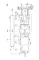
- FIG. 1 is an overall block diagram of a vehicle 100 according to the present embodiment of the present invention.
- vehicle 100 is a hybrid vehicle having a rotating electrical machine and an engine as drive sources.
- vehicle 100 includes a power storage device 110, a system main relay (SMR) 115, a drive control unit (PCU) 120, motor generators 130 and 135, and power.
- SMR system main relay
- PCU drive control unit
- a transmission gear 140, a drive wheel 150, an engine 160 as an internal combustion engine, and an ECU (Electronic Control Unit) 300 as a control device are provided.
- PCU 120 includes a converter 121, inverters 122 and 123, voltage sensors 180 and 185, and capacitors C1 and C2.
- the power storage device 110 is a power storage element configured to be chargeable / dischargeable.
- the power storage device 110 includes, for example, a secondary battery such as a lithium ion battery, a nickel metal hydride battery, or a lead storage battery, or a power storage element such as an electric double layer capacitor.
- the power storage device 110 is connected to the PCU 120 via the power lines PL1 and NL1. Then, power storage device 110 supplies power for generating driving force of vehicle 100 to PCU 120. The power storage device 110 stores the electric power generated by the motor generator 130. The output of power storage device 110 is, for example, about 200V.
- the power storage device 110 is provided with a voltage sensor 170 and a current sensor 175.
- Voltage sensor 170 detects voltage VB of power storage device 110 and outputs the detection result to ECU 300.
- Current sensor 175 detects current IB input to and output from the power storage device, and outputs the detected value to ECU 300.
- the relay included in the SMR 115 has one end connected to the positive terminal and the negative terminal of the power storage device 110 and the other end connected to the power lines PL1 and NL1 connected to the PCU 120.
- SMR 115 switches between power supply and cutoff between power storage device 110 and PCU 120 based on control signal SE ⁇ b> 1 from ECU 300.
- Converter 121 performs voltage conversion between power lines PL1, NL1 and power lines PL2, NL1 based on control signal PWC from ECU 300.
- the inverters 122 and 123 are connected to the converter 121 in parallel via the power lines PL2 and NL1.
- the inverter 122 is controlled by a control signal PWI1 from the ECU 300, converts DC power from the converter 121 into AC power, and drives a motor generator 130 (hereinafter also referred to as “MG1”). Inverter 122 also converts AC power generated by motor generator 130 into DC power, and charges power storage device 110 via converter 121.
- the inverter 123 is controlled by a control signal PWI2 from the ECU 300, converts DC power from the converter 121 into AC power, and drives a motor generator 135 (hereinafter also referred to as “MG2”). Inverter 123 also converts AC power generated by motor generator 135 into DC power, and charges power storage device 110 via converter 121.
- Motor generators 130 and 135 are AC rotating electric machines, for example, permanent magnet type synchronous motors having a rotor in which permanent magnets are embedded.
- Each output shaft of the motor generators 130 and 135 is coupled to a power transmission gear 140 including a power split mechanism such as a planetary gear. Then, the driving force from motor generators 130 and 135 is transmitted to driving wheel 150.
- the motor generators 130 and 135 are also coupled to the engine 160 via the power transmission gear 140.
- Engine 160 is controlled by control signal DRV from ECU 300.
- the driving force generated from engine 160 is transmitted to driving wheel 150 and motor generator 130 via power transmission gear 140.
- ECU 300 cooperatively controls the driving forces generated by motor generators 130 and 135 and engine 160 to cause the vehicle to travel.
- the motor generators 130 and 135 can generate electric power by being rotated by the drive wheels 150 during the regenerative braking operation of the vehicle 100. Then, the generated power is converted into charging power for power storage device 110 by PCU 120.
- motor generator 130 is used as a starter motor when starting engine 160 and is exclusively used as a generator that is driven by engine 160 to generate electric power.
- Motor generator 135 is used exclusively as an electric motor for driving drive wheels 150 using electric power from power storage device 110.
- FIG. 1 shows an example of a configuration in which two motor generators and one engine are provided.
- the number of motor generators is not limited to this. For example, even if there is one motor generator, Good. Or the case where more than two motor generators are provided may be sufficient.
- Capacitor C1 is provided between power lines PL1 and NL1, and reduces voltage fluctuation between power lines PL1 and NL1.
- Capacitor C2 is provided between power lines PL2 and NL1, and reduces voltage fluctuation between power lines PL2 and NL1.
- Voltage sensors 180 and 185 detect voltages VL and VH applied to both ends of capacitors C1 and C2, respectively, and output the detected values to ECU 300.
- a speed sensor 190 In order to detect the speed (vehicle speed) of the vehicle 100, a speed sensor 190 is provided in the vicinity of the drive wheel 150. Speed sensor 190 detects vehicle speed SPD based on the rotational speed of drive wheel 150 and outputs the detected value to ECU 300. Further, a rotation angle sensor (not shown) for detecting the rotation angle of motor generator 135 may be used as the speed sensor. In this case, ECU 300 indirectly calculates vehicle speed SPD based on a temporal change in the rotation angle of motor generator 135, a reduction ratio, and the like.
- ECU 300 includes a CPU (Central Processing Unit), a storage device, and an input / output buffer, and inputs signals from each sensor and outputs control signals to each device and stores power.
- the device 110 and each device of the vehicle 100 are controlled. Note that these controls are not limited to processing by software, and can be processed by dedicated hardware (electronic circuit).
- ECU 300 generates and outputs a control signal for controlling PCU 120, SMR 115, and the like.
- one control device is provided as the ECU 300.
- a control device for the PCU 120, a control device for the power storage device 110, or the like is provided individually for each function or for each control target device. It is good also as a structure which provides a control apparatus.
- ECU 300 calculates a state of charge (SOC) of power storage device 110 based on detected values of voltage VB and current IB from voltage sensor 170 and current sensor 175 provided in power storage device 110.
- SOC state of charge
- ECU 300 receives a required torque TR determined based on an operation of an accelerator pedal (not shown) by a user from a host ECU (not shown). ECU 300 generates control signals PWC, PWI1, and PWI2 for converter 121 and inverters 122 and 123, respectively, based on request torque TR from the user, and drives motor generators 130 and 135.
- ECU 300 receives a mode signal MOD set by the user.
- This mode signal MOD is a signal for instructing whether or not to execute inertial traveling control to be described later.
- the mode signal MOD is switched by the user by a specific switch or setting on the operation screen. Alternatively, the mode signal MOD may be automatically set in response to the establishment of a specific condition.
- ECU 300 for example, operates to perform inertial running control when mode signal MOD is set to ON, and does not perform inertial running control when mode signal MOD is set to OFF. It operates so as to perform the running.
- inertial force Since the inertial force is applied to the vehicle while the vehicle is running, if the driving force generated by the motor generator and engine during driving is lower than the driving force required to maintain the vehicle speed, gradually Although the vehicle speed decreases, traveling using the inertia force of the vehicle (hereinafter also referred to as “inertia traveling”) is continued for a while.
- traveling is performed such that the required torque from the user is substantially constant, and thereby the vehicle speed is maintained substantially constant.
- the driving power of the motor generator is switched between a high output state and a low output state while executing a continuous driving force operation that continuously outputs a constant driving force for the engine.
- Inertia travel control is performed to travel by performing the change operation. Thereby, the energy efficiency is improved while the vehicle is running.
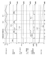
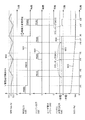
- FIG. 2 is a time chart for explaining a basic traveling pattern of the inertial traveling control in the first embodiment.
- the horizontal axis indicates time
- the vertical axis indicates vehicle speed SPD, motor generator output, engine output, required power from user, charge / discharge power of power storage device, and power storage.
- the SOC of the device is shown.
- discharging electric power is represented by the positive value and charging electric power is represented by the negative value.
- the power required by the user is given as a substantially constant value.
- the inertial traveling control according to the first embodiment is not applied.
- the EV traveling is performed by the continuous motor output PM0.
- the engine 160 is started by being cranked by the motor generator 130 (MG1) between times t1 and t2.
- the engine 160 is operated at a constant output of the output PE1 after completion of the independent operation.
- the constant output PE1 is set to an output that is smaller than the driving force capable of maintaining the current vehicle speed V1 and that causes the engine 160 to perform high-efficiency operation (that is, low fuel consumption).
- the motor generator 135 When the vehicle speed SPD falls to the lower limit value LL of the predetermined allowable range with respect to the target vehicle speed V1 (time t3 in FIG. 2), the motor generator 135 is driven. The output of the motor generator 135 is set so that the sum (PM1 + PE1) of the motor output and the engine output at this time becomes larger than the output PM0 required to maintain the vehicle speed V1. As a result, the vehicle 100 is accelerated.
- the vehicle speed SPD varies within the allowable range, but the average speed can be maintained at approximately V1.
- electricity consumption can be improved.
- the fuel consumption of the engine can be improved by adjusting the engine output so that the engine is operated in the high-efficiency operation region. As a result, energy efficiency during traveling can be improved as a whole.
- the total output (motor output + engine output) and acceleration time required when the acceleration running is executed can be arbitrarily set.
- the acceleration time may be set to a predetermined time
- the vehicle speed SPD may be set to a total output that can be increased from the lower limit value LL to the upper limit value UL within that period.
- the total output used for acceleration may be fixed to a predetermined output, and the acceleration time may be achieved.
- the acceleration time is too short, a large power is required, and a torque shock may occur.
- the acceleration time that is, the drive time of the motor generator 135 and the engine 160 becomes long, and it becomes difficult to perform inertial running. Therefore, the acceleration time and the total output during acceleration are appropriately set in consideration of drivability and energy efficiency.
- the motor generator 135 is operated so as to repeat driving and stopping.
- the motor generator 135 is not stopped during the inertia traveling, but a driving force smaller than the driving force during the acceleration traveling period is output from the motor generator 135. Also good.
- the driving force of the motor generator between the high output state and the low output state, the torque shock between the acceleration traveling and the inertia traveling can be mitigated, and drivability can be improved.
- the motor generator 135 may be operated in a low output state during the inertial running period.
- the total output in the high output state during each acceleration traveling period is not necessarily constant, and may be the same or different. Further, the total output in the low output state may be the same size or different sizes.
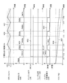
- the driving power changing operation of the motor generator as shown in FIGS. 2 and 3 is executed when the power required by the user is substantially constant. . That is, the driving force changing operation of the motor generator is not executed at the time of acceleration and deceleration when the power required by the user fluctuates.
- FIG. 4 and FIG. 5 are diagrams for explaining operations during acceleration and deceleration, respectively, when inertial traveling control is applied. 4 and 5, the horizontal axis represents time, and the vertical axis represents vehicle speed SPD, motor generator output, engine output, required power from the user, and charge / discharge power of the power storage device.
- the output PE6B of the engine 160 after the vehicle speed change may be the same as or different from the output PE1B before the vehicle speed change.
- regenerative braking may be performed by the motor generator 135 during the period when the deceleration request is received.
- motor generator 135 outputs negative motor output PM6B by regenerative power generation (dashed line W43 in FIG. 5).
- power storage device 110 is charged by the generated power (one-dot chain line W49 in FIG. 5), which increases the SOC.
- the driving force constant operation of the engine 160 and the driving force change operation of the motor generator 135 are performed. Is interrupted.
- FIG. 4 and 5 the time chart in which the output of the motor generator 135 is not zero during the inertial running period is shown.
- FIG. 4 and 5 the time chart in which the output of the motor generator 135 is not zero during the inertial running period is shown.
- FIG. 4 and 5 the driving power of the motor generator 135 in the low output state may be set to zero and the motor generator 135 may be stopped.
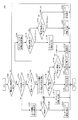
- FIG. 6 is a flowchart for illustrating an inertial traveling control process executed by ECU 300 in the first embodiment. Each step in the flowchart shown in FIG. 6 is realized by executing a program stored in ECU 300 in a predetermined cycle. Alternatively, for some steps, it is also possible to construct dedicated hardware (electronic circuit) and realize processing.
- step S 100 determines in step (hereinafter, step is abbreviated as S) 100 whether inertial running control is selected based on mode signal MOD set by the user. Determine.
- mode signal MOD is set to OFF and inertial running control is not selected (NO in S100)
- the subsequent processing is skipped, and ECU 300 returns the processing to the main routine.
- mode signal MOD is set to ON and inertial running control is selected (YES in S100)
- the process proceeds to S110, and ECU 300 next receives a request from user based on required torque TR. It is determined whether or not the required power is substantially constant.
- ECU 300 starts engine 160 to perform a driving force constant operation based on a predetermined engine output, and a motor generator It selects so that a driving force change driving
- FIG. 6 immediately after the start of the driving force change operation, as shown in FIGS. 2 to 5, the motor generator 135 is set to a low output state and the inertial running is started.
- the low output state includes a case where the driving force is zero as shown in FIG.
- ECU 300 determines in S140 whether vehicle speed SPD has increased to upper limit value UL of the allowable speed range.
- the motor generator 135 is first set to the low output state and the inertial running is executed. Therefore, the vehicle speed SPD is lower than the upper limit value UL, and the vehicle speed SPD gradually decreases. To do.
- the driving force changing operation as described above is executed so that the vehicle speed SPD is maintained within the allowable speed range.
- ECU 300 causes deceleration due to inertia traveling with motor generator 135 and engine 160 in a low output state, and lowers engine 160 to a low level. Either the output state or the deceleration accompanied by the regenerative braking by driving the motor generator 135 in the regenerative state is executed. Or you may make it decelerate, switching between the deceleration by inertial driving and the deceleration accompanying regenerative braking.
- ECU 300 selects both of engine 160 and motor generator 135 to execute the driving force changing operation.
- ECU 300 switches both motor generator 135 and engine 160 to a low output state and performs inertia.
- the running is executed (S180).
- ECU 300 switches motor generator 135 and engine 160 to a high output state and executes accelerated traveling (S182). Until the vehicle speed SPD reaches the upper limit value UL, the ECU 300 maintains the motor generator 135 and the engine 160 in a high output state and continues the acceleration travel (S184).
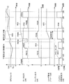
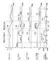
- FIGS. 7 and 8 are time charts for explaining the outline of the inertial running control in the second embodiment.
- time is shown on the horizontal axis as in FIGS. 2 and 3, and the vehicle speed SPD, motor generator output, engine output, user required power, power storage device The charge / discharge power and the SOC of the power storage device are shown.
- the output of the motor generator 135 is reduced to the constant output PM1D.
- the engine 160 is in a stopped state. In this state, the output PM1D of the motor generator 135 is smaller than the output PM0D capable of maintaining the vehicle speed V1, so the vehicle 100 travels inertial and the vehicle speed SPD gradually decreases.
- the engine 160 is cranked by the motor generator 130 and started immediately before the vehicle speed SPD falls to the lower limit value LL of the allowable range. After that, when the vehicle speed SPD decreases to the lower limit value LL of the allowable range at time t42, the engine 160 is switched to a high output state, and acceleration traveling is executed by the output PM1D from the motor generator 135 and the output PE1D from the engine 160. Is done.
- the inertia traveling and the acceleration traveling are repeatedly executed by the driving force changing operation of the engine 160.
- the motor generator 135 since the motor generator 135 is operated at a constant output, the SOC is shown in FIG. It decreases linearly as shown by the solid line W55.
- the motor generator 135 stops at the start of the next inertial traveling. (Time t48 in FIG. 7). Thereby, the power consumption in the inertial running period is suppressed.
- engine 160 is driven immediately before vehicle speed SPD reaches lower limit value LL of the allowable range, and when vehicle speed SPD decreases to lower limit value LL (time t49 in FIG. 7), the driving power of motor generator 135 and engine 160 is increased.
- the acceleration operation is executed.
- the motor generator is continuously driven with a constant output while the engine is driven with a change in driving force, and the vehicle is driven using inertial running to improve energy efficiency during vehicle running. Is possible. Then, when the SOC falls below a predetermined reference value, the degree of decrease in the SOC can be reduced by performing the driving force changing operation so that the motor generator is also switched between driving and stopping.
- motor generator 130 (MG1) is increased by increasing the driving force of engine 160 during the acceleration traveling period. ) Is driven, and power storage device 110 is charged to a predetermined level by the power generated by MG1.
- the engine 160 may not be stopped during the inertial running period, and for example, the engine 160 may be in a low output state such as idle operation. In this case, the engine 160 is in an operating state even during the inertial running period, and fuel is consumed. However, when the loss due to idle operation is smaller than the energy loss at the time of starting the engine, the engine 160 is not stopped and is reduced. The output state may improve the total energy efficiency. Therefore, for the low output state in the driving force changing operation of engine 160, the magnitude of the driving force is determined in consideration of overall energy efficiency.
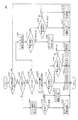
- FIG. 9 is a flowchart for illustrating an inertial traveling control process executed by ECU 300 in the second embodiment.
- steps S120, S130, S150, S152, S154, and S190 in the flowchart of FIG. 6 in the first embodiment are replaced with S120A, S130A, S150A, S152A, S154A, and S190A.
- the description of the same steps as those in FIG. 6 will not be repeated.
- SOC is greater than predetermined reference value Sth (YES in S120A)
- the process proceeds to S130A, and ECU 300 causes motor generator 135 to be smaller than the driving force that can maintain current vehicle speed SPD.
- the driving force is selected to perform a continuous driving force operation with a constant output and to perform a driving force changing operation for the engine 160.
- ECU 300 switches engine 160 to a low output state and executes inertial traveling (S150A).
- ECU 300 switches engine 160 to a high output state and executes acceleration traveling (S152A). Then, until vehicle speed SPD reaches upper limit value UL, ECU 300 keeps engine 160 in a high output state and continues the acceleration travel (S154A).
- ECU 300 switches engine 160 to the low output state again and executes inertial running.
- the subsequent processing is the same as the processing from steps S170 to S184 in the first embodiment, and the description thereof will not be repeated.
- the low output state in the driving force changing operation is intended to include the case where the driving force is zero. Then, as described in FIGS. 7 and 8, the magnitude of the driving force is appropriately set in consideration of the driving state of vehicle 100 and the energy efficiency.
- a vehicle 100A in FIG. 10 has a configuration in which the engine 160 is not provided in the vehicle 100 in FIG. 1, and the vehicle 100A travels using the driving forces of both the motor generator 130 (MG1) and the motor generator 135 (MG2). To do.
- the power storage device 110 cannot be charged as described above, but the same control can be performed by replacing the driving force of the engine 160 with the motor generator 130 in the time chart of FIG. It is possible to do.
- MG1 is also used as an electric motor instead of a generator, and when traveling using driving forces generated by three driving sources of motor generators 130 and 135 and engine 160, Applicable.
Landscapes
- Engineering & Computer Science (AREA)
- Chemical & Material Sciences (AREA)
- Combustion & Propulsion (AREA)
- Transportation (AREA)
- Mechanical Engineering (AREA)
- Automation & Control Theory (AREA)
- Electric Propulsion And Braking For Vehicles (AREA)
- Hybrid Electric Vehicles (AREA)
Abstract
Description
好ましくは、第1の駆動源は回転電機であり、第2の駆動源はエンジンである。
本発明による車両の制御方法は、第1の駆動源および第2の駆動源を含む車両についての制御方法である。制御方法は、連続的な駆動力が発生するように第1の駆動源を駆動するステップと、第1のレベルの駆動力を発生する第1の状態と第1のレベルよりも低いレベルの駆動力である第2の状態とを交互に切換えるように第2の駆動源を駆動するステップと、第1および第2の駆動源からの駆動力を用いて車両を走行させるステップとを備える。
図1は、本発明の本実施の形態に従う車両100の全体ブロック図である。以下で詳細に説明されるように、車両100は、駆動源として回転電機およびエンジンを有するハイブリッド車両である。
実施の形態1の慣性走行制御においては、上述のように、ユーザからの要求パワーがほぼ一定である場合に、図2および図3で示したようなモータジェネレータの駆動力変更運転が実行される。すなわち、ユーザからの要求パワーが変動する加速時および減速時には、モータジェネレータの駆動力変更運転は実行されない。
実施の形態1においては、慣性走行制御において、エンジン出力を一定とするとともにモータジェネレータを駆動力変更運転とする構成について説明した。
上記の実施の形態1および実施の形態2においては、複数の駆動源としてエンジンとモータジェネレータとが備えられるハイブリッド車両を例として説明したが、本発明は、複数の駆動源として、たとえば、図10に示されるような、2つのモータジェネレータからの駆動力を用いて走行することが可能なツインモータ構成の電気自動車などの、他の構成を有する車両にも適用可能である。
Claims (15)
- 車両であって、
前記車両(100)の走行駆動力を発生する第1の駆動源および第2の駆動源(130,135,160)と、
前記第1および第2の駆動源(130,135,160)を制御するための制御装置(300)とを備え、
前記制御装置(300)は、前記第1の駆動源については駆動力を連続的に発生するように駆動する連続駆動力運転を実行するとともに、前記第2の駆動源については、第1のレベルの駆動力を発生する第1の状態と、前記第1のレベルよりも低いレベルの駆動力である第2の状態とを交互に切換える駆動力変更運転を実行して前記車両(100)を走行させる、車両。 - 前記制御装置(300)は、ユーザからの要求駆動力の変化が所定範囲内の場合に、前記第2の駆動源において前記駆動力変更運転を実行する、請求項1に記載の車両。
- 前記制御装置(300)は、前記第2の駆動源において前記駆動力変更運転を実行している間は、前記車両(100)の速度が許容範囲内に維持されるように、前記第2の駆動源について前記第1および第2の状態を切換える、請求項2に記載の車両。
- 前記制御装置(300)は、前記車両(100)の速度が前記許容範囲の上限まで上昇したことに応答して前記第2の駆動源を前記第2の状態に切換え、前記車両(100)の速度が前記許容範囲の下限まで低下したことに応答して前記第2の駆動源を前記第1の状態に切換える、請求項3に記載の車両。
- 前記第1の駆動源が発生する駆動力と、前記第2の駆動源が前記第2の状態における駆動力との和は、前記車両(100)の速度を維持することが可能な一定出力の基準駆動力よりも小さく設定され、
前記第1の駆動源が発生する駆動力と、前記第2の駆動源が前記第1の状態における駆動力との和は、前記基準駆動力よりも大きく設定される、請求項1に記載の車両。 - 前記車両(100)は、前記第2の駆動源が前記第2の状態のときには、主に前記車両(100)の慣性力によって走行する、請求項5に記載の車両。
- 前記第1の駆動源が発生する駆動力は、予め定められた所定の駆動力に設定される、請求項1に記載の車両。
- 前記制御装置(300)は、前記第2の駆動源が前記第2の状態のときには、前記第2の駆動源からの駆動力の発生を停止する、請求項7に記載の車両。
- 前記第1の駆動源は、エンジン(160)であり、
前記第2の駆動源は、回転電機(135)である、請求項1に記載の車両。 - 前記第1の駆動源は、回転電機(135)であり、
前記第2の駆動源は、エンジン(160)である、請求項1に記載の車両。 - 前記回転電機に電力を供給するための蓄電装置(110)をさらに備え、
前記制御装置(300)は、前記エンジン(160)が前記駆動力変更運転を実行中に、前記蓄電装置(110)の充電状態が予め定められたしきい値を下回ったときは、前記回転電機(135)について、前記連続駆動力運転を中止し、第2のレベルの駆動力を発生する第3の状態と、前記第2のレベルよりも低いレベルの駆動力を発生する第4の状態とを交互に切換えるように運転する、請求項10に記載の車両。 - 前記制御装置(300)は、前記エンジン(160)が前記駆動力変更運転を実行中に、前記蓄電装置(110)の充電状態が前記予め定められたしきい値を下回ったときは、前記エンジン(160)が前記第1の状態の期間に前記回転電機(135)を前記第3の状態に切換え、前記エンジン(160)が前記第2の状態の期間に前記回転電機(135)を前記第4の状態に切換える、請求項11に記載の車両。
- 前記制御装置(300)は、前記回転電機(135)が前記第4の状態ときには、前記回転電機(135)からの駆動力の発生を停止する、請求項12に記載の車両。
- 前記第1および第2の駆動源の各々は、回転電機(130,135)である、請求項1に記載の車両。
- 第1の駆動源および第2の駆動源(130,135,160)を含む車両の制御方法であって、
連続的な駆動力が発生するように、前記第1の駆動源を駆動するステップと、
第1のレベルの駆動力を発生する第1の状態と、前記第1のレベルよりも低いレベルの駆動力である第2の状態とを交互に切換えるように、前記第2の駆動源を駆動するステップと、
前記第1および第2の駆動源からの駆動力を用いて前記車両(100)を走行させるステップとを備える、車両の制御方法。
Priority Applications (4)
| Application Number | Priority Date | Filing Date | Title |
|---|---|---|---|
| CN201180073663.0A CN103826951A (zh) | 2011-09-27 | 2011-09-27 | 车辆和车辆的控制方法 |
| US14/344,511 US9162670B2 (en) | 2011-09-27 | 2011-09-27 | Vehicle and method of controlling vehicle |
| EP11873538.0A EP2762375A4 (en) | 2011-09-27 | 2011-09-27 | VEHICLE AND VEHICLE CONTROL PROCEDURE |
| PCT/JP2011/071977 WO2013046312A1 (ja) | 2011-09-27 | 2011-09-27 | 車両および車両の制御方法 |
Applications Claiming Priority (1)
| Application Number | Priority Date | Filing Date | Title |
|---|---|---|---|
| PCT/JP2011/071977 WO2013046312A1 (ja) | 2011-09-27 | 2011-09-27 | 車両および車両の制御方法 |
Publications (1)
| Publication Number | Publication Date |
|---|---|
| WO2013046312A1 true WO2013046312A1 (ja) | 2013-04-04 |
Family
ID=47994429
Family Applications (1)
| Application Number | Title | Priority Date | Filing Date |
|---|---|---|---|
| PCT/JP2011/071977 WO2013046312A1 (ja) | 2011-09-27 | 2011-09-27 | 車両および車両の制御方法 |
Country Status (4)
| Country | Link |
|---|---|
| US (1) | US9162670B2 (ja) |
| EP (1) | EP2762375A4 (ja) |
| CN (1) | CN103826951A (ja) |
| WO (1) | WO2013046312A1 (ja) |
Cited By (1)
| Publication number | Priority date | Publication date | Assignee | Title |
|---|---|---|---|---|
| JPWO2013046312A1 (ja) * | 2011-09-27 | 2015-03-26 | トヨタ自動車株式会社 | 車両および車両の制御方法 |
Families Citing this family (3)
| Publication number | Priority date | Publication date | Assignee | Title |
|---|---|---|---|---|
| US9346363B2 (en) * | 2012-08-13 | 2016-05-24 | Mitsubishi Electric Corporation | Propulsion control apparatus of engine hybrid railroad vehicle |
| SE1350152A1 (sv) * | 2013-02-08 | 2014-08-09 | BAE Systems Hägglunds Aktiebolag | Förfarande och system för styrning av ett fordons drivlina |
| FR3004231B1 (fr) * | 2013-04-05 | 2015-04-03 | Renault Sa | Procede de controle de l'etat d'une chaine cinematique d'un groupe motopropulseur de vehicule electrique hybride ou thermique |
Citations (5)
| Publication number | Priority date | Publication date | Assignee | Title |
|---|---|---|---|---|
| JPS5090020A (ja) * | 1973-12-18 | 1975-07-18 | ||
| JP2007187090A (ja) | 2006-01-13 | 2007-07-26 | Toyota Motor Corp | 速度維持制御装置 |
| JP2008520485A (ja) | 2004-11-16 | 2008-06-19 | フォルクスワーゲン・アクチェンゲゼルシャフト | ハイブリッド自動車及びハイブリッド自動車の動作制御法 |
| JP2009298232A (ja) | 2008-06-11 | 2009-12-24 | Toyota Motor Corp | ハイブリッド車およびその制御方法 |
| JP2010006309A (ja) | 2008-06-30 | 2010-01-14 | Toyota Motor Corp | 車両用制御装置 |
Family Cites Families (18)
| Publication number | Priority date | Publication date | Assignee | Title |
|---|---|---|---|---|
| JP3646962B2 (ja) * | 1998-01-12 | 2005-05-11 | 富士重工業株式会社 | ハイブリッド車 |
| JP3376918B2 (ja) | 1998-06-17 | 2003-02-17 | 日産自動車株式会社 | 車両用定速走行制御システム |
| JP3563314B2 (ja) | 1999-11-25 | 2004-09-08 | 本田技研工業株式会社 | ハイブリッド車両のオートクルーズ制御装置 |
| JP4636651B2 (ja) * | 2000-04-07 | 2011-02-23 | Gknドライブラインジャパン株式会社 | 動力伝達装置 |
| JP2002106378A (ja) * | 2000-10-02 | 2002-04-10 | Takayuki Miyao | 無段変速機のハイブリッド駆動方法 |
| JP3931810B2 (ja) * | 2002-12-27 | 2007-06-20 | アイシン・エィ・ダブリュ株式会社 | 車輌の制御装置 |
| EP1466775A3 (en) * | 2003-04-10 | 2010-09-15 | Nissan Motor Company Limited | Drive controlling apparatus and method for automotive vehicle |
| DE102004017115A1 (de) * | 2004-04-07 | 2005-10-27 | Zf Friedrichshafen Ag | Verfahren zur Geschwindigkeitsregelung für ein Fahrzeug mit automatischem oder automatisiertem Getriebe |
| JP4005069B2 (ja) * | 2004-09-03 | 2007-11-07 | 本田技研工業株式会社 | ハイブリッド車両の制御装置 |
| JP4529726B2 (ja) * | 2005-02-23 | 2010-08-25 | トヨタ自動車株式会社 | 動力出力装置、動力出力装置の制御方法及びそれを搭載した車両 |
| JP4321619B2 (ja) * | 2007-03-30 | 2009-08-26 | トヨタ自動車株式会社 | 車両およびその制御方法 |
| DE102008005644A1 (de) * | 2008-01-23 | 2009-07-30 | Wilhelm Meiners | Verfahren zur Kraftstoffeinsparung bei KFZ mit Verbrennungsmotor durch zyklische Betriebsweise |
| JP4596016B2 (ja) * | 2008-02-12 | 2010-12-08 | トヨタ自動車株式会社 | 車輌走行制御装置 |
| JP4453765B2 (ja) * | 2008-02-26 | 2010-04-21 | トヨタ自動車株式会社 | ハイブリッド車およびその制御方法 |
| KR101114381B1 (ko) * | 2009-11-19 | 2012-02-14 | 현대자동차주식회사 | 하이브리드 차량의 경제운전 제어장치 및 방법 |
| IT1398820B1 (it) * | 2009-12-16 | 2013-03-21 | Magneti Marelli Spa | Metodo di controllo della velocita'di un veicolo con alternanza di moto attivo e moto passivo |
| DE102010007632A1 (de) * | 2010-02-05 | 2011-08-11 | Dr. Ing. h.c. F. Porsche Aktiengesellschaft, 70435 | Hybridfahrzeug |
| US8433465B2 (en) * | 2010-06-08 | 2013-04-30 | Ford Global Technologies, Llc | Transitioning between series-drive and parallel-drive in a hybrid-electric vehicle powertrain |
-
2011
- 2011-09-27 EP EP11873538.0A patent/EP2762375A4/en not_active Withdrawn
- 2011-09-27 CN CN201180073663.0A patent/CN103826951A/zh active Pending
- 2011-09-27 WO PCT/JP2011/071977 patent/WO2013046312A1/ja active Application Filing
- 2011-09-27 US US14/344,511 patent/US9162670B2/en not_active Expired - Fee Related
Patent Citations (5)
| Publication number | Priority date | Publication date | Assignee | Title |
|---|---|---|---|---|
| JPS5090020A (ja) * | 1973-12-18 | 1975-07-18 | ||
| JP2008520485A (ja) | 2004-11-16 | 2008-06-19 | フォルクスワーゲン・アクチェンゲゼルシャフト | ハイブリッド自動車及びハイブリッド自動車の動作制御法 |
| JP2007187090A (ja) | 2006-01-13 | 2007-07-26 | Toyota Motor Corp | 速度維持制御装置 |
| JP2009298232A (ja) | 2008-06-11 | 2009-12-24 | Toyota Motor Corp | ハイブリッド車およびその制御方法 |
| JP2010006309A (ja) | 2008-06-30 | 2010-01-14 | Toyota Motor Corp | 車両用制御装置 |
Non-Patent Citations (1)
| Title |
|---|
| See also references of EP2762375A4 |
Cited By (1)
| Publication number | Priority date | Publication date | Assignee | Title |
|---|---|---|---|---|
| JPWO2013046312A1 (ja) * | 2011-09-27 | 2015-03-26 | トヨタ自動車株式会社 | 車両および車両の制御方法 |
Also Published As
| Publication number | Publication date |
|---|---|
| US20140343777A1 (en) | 2014-11-20 |
| US9162670B2 (en) | 2015-10-20 |
| EP2762375A4 (en) | 2016-01-27 |
| EP2762375A1 (en) | 2014-08-06 |
| CN103826951A (zh) | 2014-05-28 |
Similar Documents
| Publication | Publication Date | Title |
|---|---|---|
| JP5692405B2 (ja) | 車両および車両の制御方法 | |
| JP5804074B2 (ja) | 車両および車両の制御方法 | |
| JP6003943B2 (ja) | ハイブリッド車両およびハイブリッド車両の制御方法 | |
| JP5696791B2 (ja) | 車両および車両の制御方法 | |
| WO2012098658A1 (ja) | ハイブリッド車両およびその制御方法 | |
| JP6100690B2 (ja) | 車両 | |
| JP5696790B2 (ja) | 車両および車両の制御方法 | |
| JP5825287B2 (ja) | ハイブリッド車両 | |
| JP5811181B2 (ja) | 車両および車両の制御方法 | |
| WO2012137329A1 (ja) | ハイブリッド車両およびその制御方法 | |
| JP2016155484A (ja) | ハイブリッド車両 | |
| WO2013046310A1 (ja) | 車両および車両の制御方法 | |
| WO2013046312A1 (ja) | 車両および車両の制御方法 | |
| JP6149814B2 (ja) | ハイブリッド車両 | |
| WO2013061413A1 (ja) | 車両および車両の制御方法 | |
| WO2013061414A1 (ja) | 車両および車両の制御方法 | |
| JPWO2013046312A1 (ja) | 車両および車両の制御方法 | |
| JP2014073788A (ja) | ハイブリッド車両およびハイブリッド車両の制御方法 | |
| JP2013099227A (ja) | 車両および車両の制御方法 | |
| JPWO2013061414A1 (ja) | 車両および車両の制御方法 | |
| JPWO2013046310A1 (ja) | 車両および車両の制御方法 | |
| JP5765192B2 (ja) | 車両および車両の制御方法 | |
| JP2013086725A (ja) | 車両および車両の制御方法 |
Legal Events
| Date | Code | Title | Description |
|---|---|---|---|
| 121 | Ep: the epo has been informed by wipo that ep was designated in this application |
Ref document number: 11873538 Country of ref document: EP Kind code of ref document: A1 |
|
| WWE | Wipo information: entry into national phase |
Ref document number: 14344511 Country of ref document: US |
|
| ENP | Entry into the national phase |
Ref document number: 2013535671 Country of ref document: JP Kind code of ref document: A |
|
| NENP | Non-entry into the national phase |
Ref country code: DE |
|
| REEP | Request for entry into the european phase |
Ref document number: 2011873538 Country of ref document: EP |
|
| WWE | Wipo information: entry into national phase |
Ref document number: 2011873538 Country of ref document: EP |