WO2013042351A1 - Led照明装置 - Google Patents
Led照明装置 Download PDFInfo
- Publication number
- WO2013042351A1 WO2013042351A1 PCT/JP2012/005943 JP2012005943W WO2013042351A1 WO 2013042351 A1 WO2013042351 A1 WO 2013042351A1 JP 2012005943 W JP2012005943 W JP 2012005943W WO 2013042351 A1 WO2013042351 A1 WO 2013042351A1
- Authority
- WO
- WIPO (PCT)
- Prior art keywords
- cooling
- led
- cooling cylinder
- back surface
- mounting plate
- Prior art date
- Legal status (The legal status is an assumption and is not a legal conclusion. Google has not performed a legal analysis and makes no representation as to the accuracy of the status listed.)
- Ceased
Links
Images


Classifications
-
- F—MECHANICAL ENGINEERING; LIGHTING; HEATING; WEAPONS; BLASTING
- F21—LIGHTING
- F21V—FUNCTIONAL FEATURES OR DETAILS OF LIGHTING DEVICES OR SYSTEMS THEREOF; STRUCTURAL COMBINATIONS OF LIGHTING DEVICES WITH OTHER ARTICLES, NOT OTHERWISE PROVIDED FOR
- F21V29/00—Protecting lighting devices from thermal damage; Cooling or heating arrangements specially adapted for lighting devices or systems
- F21V29/50—Cooling arrangements
- F21V29/70—Cooling arrangements characterised by passive heat-dissipating elements, e.g. heat-sinks
- F21V29/74—Cooling arrangements characterised by passive heat-dissipating elements, e.g. heat-sinks with fins or blades
- F21V29/77—Cooling arrangements characterised by passive heat-dissipating elements, e.g. heat-sinks with fins or blades with essentially identical diverging planar fins or blades, e.g. with fan-like or star-like cross-section
- F21V29/773—Cooling arrangements characterised by passive heat-dissipating elements, e.g. heat-sinks with fins or blades with essentially identical diverging planar fins or blades, e.g. with fan-like or star-like cross-section the planes containing the fins or blades having the direction of the light emitting axis
-
- F—MECHANICAL ENGINEERING; LIGHTING; HEATING; WEAPONS; BLASTING
- F21—LIGHTING
- F21V—FUNCTIONAL FEATURES OR DETAILS OF LIGHTING DEVICES OR SYSTEMS THEREOF; STRUCTURAL COMBINATIONS OF LIGHTING DEVICES WITH OTHER ARTICLES, NOT OTHERWISE PROVIDED FOR
- F21V29/00—Protecting lighting devices from thermal damage; Cooling or heating arrangements specially adapted for lighting devices or systems
- F21V29/50—Cooling arrangements
- F21V29/70—Cooling arrangements characterised by passive heat-dissipating elements, e.g. heat-sinks
- F21V29/74—Cooling arrangements characterised by passive heat-dissipating elements, e.g. heat-sinks with fins or blades
- F21V29/78—Cooling arrangements characterised by passive heat-dissipating elements, e.g. heat-sinks with fins or blades with helically or spirally arranged fins or blades
-
- F—MECHANICAL ENGINEERING; LIGHTING; HEATING; WEAPONS; BLASTING
- F21—LIGHTING
- F21K—NON-ELECTRIC LIGHT SOURCES USING LUMINESCENCE; LIGHT SOURCES USING ELECTROCHEMILUMINESCENCE; LIGHT SOURCES USING CHARGES OF COMBUSTIBLE MATERIAL; LIGHT SOURCES USING SEMICONDUCTOR DEVICES AS LIGHT-GENERATING ELEMENTS; LIGHT SOURCES NOT OTHERWISE PROVIDED FOR
- F21K9/00—Light sources using semiconductor devices as light-generating elements, e.g. using light-emitting diodes [LED] or lasers
- F21K9/20—Light sources comprising attachment means
-
- F—MECHANICAL ENGINEERING; LIGHTING; HEATING; WEAPONS; BLASTING
- F21—LIGHTING
- F21S—NON-PORTABLE LIGHTING DEVICES; SYSTEMS THEREOF; VEHICLE LIGHTING DEVICES SPECIALLY ADAPTED FOR VEHICLE EXTERIORS
- F21S8/00—Lighting devices intended for fixed installation
- F21S8/02—Lighting devices intended for fixed installation of recess-mounted type, e.g. downlighters
-
- F—MECHANICAL ENGINEERING; LIGHTING; HEATING; WEAPONS; BLASTING
- F21—LIGHTING
- F21V—FUNCTIONAL FEATURES OR DETAILS OF LIGHTING DEVICES OR SYSTEMS THEREOF; STRUCTURAL COMBINATIONS OF LIGHTING DEVICES WITH OTHER ARTICLES, NOT OTHERWISE PROVIDED FOR
- F21V29/00—Protecting lighting devices from thermal damage; Cooling or heating arrangements specially adapted for lighting devices or systems
- F21V29/50—Cooling arrangements
- F21V29/56—Cooling arrangements using liquid coolants
-
- F—MECHANICAL ENGINEERING; LIGHTING; HEATING; WEAPONS; BLASTING
- F21—LIGHTING
- F21V—FUNCTIONAL FEATURES OR DETAILS OF LIGHTING DEVICES OR SYSTEMS THEREOF; STRUCTURAL COMBINATIONS OF LIGHTING DEVICES WITH OTHER ARTICLES, NOT OTHERWISE PROVIDED FOR
- F21V29/00—Protecting lighting devices from thermal damage; Cooling or heating arrangements specially adapted for lighting devices or systems
- F21V29/50—Cooling arrangements
- F21V29/70—Cooling arrangements characterised by passive heat-dissipating elements, e.g. heat-sinks
- F21V29/74—Cooling arrangements characterised by passive heat-dissipating elements, e.g. heat-sinks with fins or blades
- F21V29/77—Cooling arrangements characterised by passive heat-dissipating elements, e.g. heat-sinks with fins or blades with essentially identical diverging planar fins or blades, e.g. with fan-like or star-like cross-section
-
- F—MECHANICAL ENGINEERING; LIGHTING; HEATING; WEAPONS; BLASTING
- F21—LIGHTING
- F21S—NON-PORTABLE LIGHTING DEVICES; SYSTEMS THEREOF; VEHICLE LIGHTING DEVICES SPECIALLY ADAPTED FOR VEHICLE EXTERIORS
- F21S8/00—Lighting devices intended for fixed installation
- F21S8/04—Lighting devices intended for fixed installation intended only for mounting on a ceiling or the like overhead structures
-
- F—MECHANICAL ENGINEERING; LIGHTING; HEATING; WEAPONS; BLASTING
- F21—LIGHTING
- F21W—INDEXING SCHEME ASSOCIATED WITH SUBCLASSES F21K, F21L, F21S and F21V, RELATING TO USES OR APPLICATIONS OF LIGHTING DEVICES OR SYSTEMS
- F21W2131/00—Use or application of lighting devices or systems not provided for in codes F21W2102/00-F21W2121/00
- F21W2131/10—Outdoor lighting
- F21W2131/101—Outdoor lighting of tunnels or the like, e.g. under bridges
-
- F—MECHANICAL ENGINEERING; LIGHTING; HEATING; WEAPONS; BLASTING
- F21—LIGHTING
- F21Y—INDEXING SCHEME ASSOCIATED WITH SUBCLASSES F21K, F21L, F21S and F21V, RELATING TO THE FORM OR THE KIND OF THE LIGHT SOURCES OR OF THE COLOUR OF THE LIGHT EMITTED
- F21Y2105/00—Planar light sources
- F21Y2105/10—Planar light sources comprising a two-dimensional [2D] array of point-like light-generating elements
-
- F—MECHANICAL ENGINEERING; LIGHTING; HEATING; WEAPONS; BLASTING
- F21—LIGHTING
- F21Y—INDEXING SCHEME ASSOCIATED WITH SUBCLASSES F21K, F21L, F21S and F21V, RELATING TO THE FORM OR THE KIND OF THE LIGHT SOURCES OR OF THE COLOUR OF THE LIGHT EMITTED
- F21Y2115/00—Light-generating elements of semiconductor light sources
- F21Y2115/10—Light-emitting diodes [LED]
Definitions
- the present invention relates to an illumination device using an LED (Light Emitting Diode), and more particularly to an illumination device incorporating a heat sink.
- LED Light Emitting Diode
- LEDs using LEDs have become widespread as one of the solutions to meet the recent problem of energy saving. Since LEDs have the characteristic of long life in addition to low power consumption, related technologies have been studied all over the world, and it can be said that they are very fast-evolving semiconductors. In the past, it was limited to products with low power consumption such as display lamps, but with the development of high-power LED elements, in recent years, high-power lighting devices utilizing this have also appeared. The illumination effect of the LED lighting device is very high, and there are some that exceed fluorescent lamps. Further, since the LED light is irradiated in a straight line, the illuminance value is higher than the total luminous flux value and emits a strong light beam.
- an LED lighting device having a structure including a substrate on which an LED element for illumination is mounted, a base for fixing the substrate, and a heat sink made of a heat pipe, a heat radiating fin, or the like that moves heat generated from the LED. ing.
- the conventional LED lighting device has a complicated structure because it requires various components such as a base, a heat pipe, and a heat radiating fin for fixing a substrate on which the LED element is mounted.
- the degree of adhesion between the heat pipe and the component in contact with the heat pipe is high, but actually, due to factors such as the difference in each material and shape, It is difficult to configure with high adhesion.
- the present invention has been made in view of the above points, and intends to provide an LED lighting device capable of suppressing heat resistance lower than that of the prior art and further efficiently dissipating heat generated from LED elements. Is.
- the present invention includes an illumination unit having a substrate on which a plurality of LED elements are mounted and a support member that supports the substrate, and a cooling unit that supports and cools the support member.
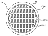
- the support member includes a mounting plate portion in which one surface in the thickness direction is an attachment surface to which the substrate is attached and the other surface in the thickness direction is a back surface.
- the cooling section has a length, one end in the longitudinal direction is opened and the other end is closed, and the one end of the cooling cylinder is closed on the back surface, thereby An internal space formed inside, and a cooling hydraulic fluid sealed in the internal space, and the support member is supported at the one end of the cooling cylinder, and is viewed from the thickness direction of the mounting plate portion.
- the actual inside of the back surface located in the internal space.
- a number of recesses separated from each other recess on the mounting surface side characterized in that it is formed in a honeycomb shape.
- Heat generated from the LED elements during operation of the LED lighting device is conducted from the attachment surface to the attachment plate portion through the substrate, and from the attachment plate portion to the cooling working fluid.
- the cooling working fluid When heat is conducted to the cooling working fluid, the cooling working fluid is easily evaporated and vaporized, and the heat of the vaporized cooling working fluid is conducted to the cooling cylinder and radiated to the outside. In this way, when the heat of condensation is released at the upper part of the internal space, the cooling working fluid is cooled and liquefied, and returned to the mounting plate portion by gravity, and the circulation of the cooling working fluid continues. Done.
- the rigidity of the mounting plate portion is ensured by a wall having a height located between adjacent recesses, and against the saturated vapor pressure of the cooling working fluid and at the time of injection of the cooling working fluid.
- the mounting plate portion can withstand a vacuum state or a reduced pressure state close to vacuum without deformation. Therefore, since the rigidity of the mounting plate portion is ensured by the wall portion having a height located between the adjacent concave portions, the wall portion forming the bottom surface of the concave portion can be thinned.
- all the LED elements when viewed from the thickness direction of the mounting plate portion, all the LED elements are located inside the back surface located in the internal space, and the wall portion forming the bottom surface of the recess is thin. Therefore, the heat generated from all the LED elements is effectively conducted to the cooling working fluid through the thin wall portion forming the bottom surface of the recess, which is extremely advantageous for effectively cooling all the LED elements. .
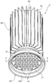
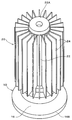
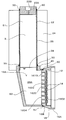
- the LED lighting device 2 includes an illumination unit 10 and a cooling unit 20 that supports the illumination unit 10, and is enclosed in an internal space S of the cooling unit 20.
- the plurality of LED elements 14 of the illuminating unit 10 are cooled by the evaporation heat of the cooling working fluid 28 thus formed.
- the LED illumination device 2 of the embodiment shown in FIGS. 1 to 6 is used while being supported in such a direction that the LED irradiation light is irradiated vertically downward.
- the LED lighting device 2 is placed on the upper wall or side wall in the tunnel, and if the use location is a building, the LED illumination device 2 is placed on a ceiling or a wall surface.
- Various known attachments are provided in the cooling unit 20 or the illumination unit 10, but are omitted in the drawing.
- the illumination unit 10 includes a substrate 12, an LED element 14, and a support member 16.
- the substrate 12 has a circular shape, and a plurality of LED elements 14 are mounted on the substrate 12.
- the support member 16 includes an attachment plate portion 16A and a reflector 16B.
- the mounting plate portion 16A has a circular shape, and as shown in FIG. 5, one surface in the thickness direction of the mounting plate portion 16A is a mounting surface 1602 to which the substrate 12 is attached, and the other surface in the thickness direction. Is the back 1604.
- the mounting plate portion 16A supports the substrate 12 from the vertical upper side by the mounting surface 1602 in a state where the mounting plate portion 16A is horizontal, and directs the plurality of LED elements 14 mounted on the substrate 12 downward in the vertical direction.
- the reflector 16B is provided around the mounting plate portion 16A so as to cover the periphery of the substrate 12.
- the reflector 16B reflects and collects the irradiation light from the LED element 14, and irradiates the light with a desired irradiation amount.
- a large number of recesses 1610 that are recessed toward the attachment surface 1602 and separated from each other are formed in a honeycomb shape over the entire back surface 1604 of the attachment plate portion 16A located in the internal space S.
- a large number of recesses 1610 are formed in a state of being close to each other.
- the recess 1610 has a circular cross section. Therefore, as shown in FIG. 5, the mounting plate portion 16 ⁇ / b> A extends over and adjoins the wall portion 1620 positioned between the bottom surface 1610 ⁇ / b> A and the mounting surface 1602 of the multiple recesses 1610, the mounting surface 1602 and the back surface 1604.
- Recess 1610 has a bottom surface 1610A and a side surface 1610B that rises from the periphery of bottom surface 1610A and is connected to back surface 1604. Further, in the present embodiment, the boundary portion between bottom surface 1610A and side surface 1610B is connected by concave curved surface 1610C.
- the plurality of LED elements 14 are arranged so that the centers of the LED elements 14 are located at locations on the substrate 12 that are positioned on the extension of the axis CL of the recess 1610.
- the rigidity of the mounting plate portion 16A is ensured by the height of the wall portion 1622, and against the saturated vapor pressure of the cooling working fluid 28 acting on the mounting plate portion 16A, and for cooling
- the mounting plate portion 16A can withstand a vacuum state at the time of injection of the working fluid 28 or a reduced pressure state close to a vacuum without deformation. Therefore, since the rigidity of the mounting plate portion 16A is ensured by the wall portion 1622, the wall portion 1620 forming the bottom surface 1610A of the recess portion 1610 can be thinned, and the heat generated from the LED element 14 can be effectively applied to the cooling working fluid 28. This is extremely advantageous in effectively cooling the LED element 14. In this case, as shown in FIG.
- the cooling unit 20 supports the support member 16 and moves and dissipates the heat generated from the LED elements 14 during the operation of the LED lighting device 2. Therefore, the cooling unit 20 also serves as a heat sink having a heat pipe function.
- the cooling unit 20 includes a cooling cylinder 22, a radiation fin 24, an internal space S, and a cooling working fluid 28.
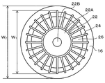
- One end portion of the cooling cylinder 22 in the longitudinal direction is opened, and the opened end portion is closed by the back surface 1604 of the mounting plate portion 16A.
- a plug-like sealing portion 22A is provided at the other end in the longitudinal direction of the cooling cylinder 22, and, as will be described later, after the cooling working fluid 28 is injected into the internal space S, the hole of the sealing portion 22A is provided. 22B is closed by welding without a gap.
- One end in the longitudinal direction of the cooling cylinder 22 is closed by the back surface 1604 of the mounting plate portion 16A, and the other end in the longitudinal direction is closed by the sealing portion 22A, so that an internal space S is formed inside the cooling
- the cooling cylinder 22 includes a cylindrical body 25 and a hollow intermediate connecting member 26 that is attached to the end of the cylindrical body 25 in the longitudinal direction and supports the mounting plate portion 16A.
- the radiating fins 24 extend over the entire length of the cylindrical body 25, are provided on the outer peripheral surface of the cylindrical body 25 at intervals in the circumferential direction, and are provided integrally with the cylindrical body 25.
- the diameter of the illumination unit 10 is larger than the diameter of the cylindrical body 25 as in the LED lighting device 2 of this embodiment, that is, the region where the plurality of LED elements 14 are arranged is the cross-sectional area of the cylindrical body 25. If larger than that, the provision of the intermediate connection member 26 is advantageous in firmly connecting the illumination unit 10 and the cooling unit 20 to each other.
- the intermediate connecting member 26 is hollow and has a base attached to the end of the cylindrical body 25 and an inclined part that gradually increases in diameter from the base. Therefore, the internal space S includes a cylindrical space portion S1 that extends in a straight line with a uniform cross section defined inside the cylindrical body 25, and an end portion in the longitudinal direction of the cylindrical space portion S1 that is formed inside the intermediate connection member 26. And a conical space portion S2 whose cross-sectional area gradually increases as it moves away from the cylindrical space portion S1. Further, the portion of the cooling portion 20 that supports the support member 16 becomes an end portion of the intermediate connection member 26 that forms the conical space portion S2 on the side away from the cylindrical space portion S1, and the cooling cylinder 22 that is closed by the back surface 1604. The opened end becomes the end of the conical space S2 on the side away from the cylindrical space S1.
- the intermediate connection member 26 by providing the intermediate connection member 26, a plurality of components mounted on the inner side of the back surface 1604 located in the internal space S when viewed from the thickness direction of the mounting plate portion 16 ⁇ / b> A.
- the mounting plate portion 16A is provided so that the LED elements 14 are positioned, and all the LED elements are efficiently cooled by the evaporation heat of the cooling working fluid 28.
- the cooling unit 20 including the heat radiation fins 24 is accommodated in the lighting unit 10 including the support member 16 when viewed from the axial direction of the cooling cylinder 22. It is as a structure.
- the diameter W1 of the cooling unit 20 including the radiation fins 24 is set to a size equal to or smaller than the diameter W2 of the support member 16. That is, the outline of the cooling unit 20 including the plurality of heat dissipating fins 24 in a plan view is arranged to be inside the outline of the illumination unit 10.
- the cylindrical body 25, the intermediate connecting member 26, and the support member 16 are made of a material having high thermal conductivity, and can withstand a vacuum state when the cooling working fluid 28 is injected, and when used, the cooling working fluid is used. It is made of a material that can withstand a saturated vapor pressure of 28. For example, lightweight aluminum with high thermal conductivity is suitable. In addition, it is advantageous to reduce costs by manufacturing by a die casting method or the like. Further, welding is used for the attachment of the sealing portion 22A to the cylindrical body 25, the attachment of the cylindrical body 25 and the intermediate connection member 26, and the attachment of the intermediate connection member 26 and the support member 16, and for a long time between these members. The state without a gap is maintained, and the durability of the LED lighting device 2 is enhanced. In addition, the code
- the cooling unit 20 also serves as a heat sink having a heat pipe function.
- the cooling hydraulic fluid 28 is a cooling operation in which the entire area of the back surface 1604 of the mounting plate portion 16A is in a state where the longitudinal direction of the cooling cylinder 22 (specifically, the longitudinal direction of the cylindrical body 25 of the cooling cylinder 22) is oriented in the vertical direction. It is enclosed in an amount that is always immersed in the liquid 28.
- the liquid portion 28A due to the cooling working fluid 28 is always present in the lower portion of the internal space S, and the liquid level is always positioned above the entire area of the back surface 1604 of the mounting plate portion 16A. Is enclosed.
- the cooling hydraulic fluid 28 various conventionally known liquids such as liquids such as water and alcohol, and highly insulating and non-flammable liquids such as silicon oil can be used.
- the cooling working fluid 28 is sealed up to the lower end of the cylindrical space S1.
- the cooling fluid 28 is injected into the internal space S from the hole 22B of the sealing portion 22A with the internal space S in a vacuum state or a reduced pressure state close to vacuum, and after the injection, the hole 22B has no gap by welding. Is blocked.
- Heat generated from the LED element 14 during operation of the LED lighting device 2 is conducted from the attachment surface 1602 to the attachment plate portion 16A through the substrate 12, and from the attachment plate portion 16A to the cooling working fluid 28 of the liquid portion 28A. .
- the cooling working fluid 28 is easily evaporated and vaporized.
- the vaporized cooling fluid 28 rises in the internal space S, and the heat of the vaporized cooling fluid 28 is conducted to the radiation fins 24 through the cooling cylinder 22 and is radiated from the radiation fins 24 to the outside. Is done.
- the heat of condensation is released at the upper part of the internal space S, whereby the cooling working fluid 28 is cooled and liquefied, and is returned again to the liquid portion 28A on the mounting plate portion 16A by gravity.
- the working fluid 28 is circulated continuously.
- the cooling unit 20 itself has a structure that functions as a heat pipe that functions as a heat pipe that moves and dissipates heat generated from the LED elements 14. Therefore, it is possible to dissipate the heat generated from the LED element 14 efficiently without worrying about an increase in thermal resistance, although it has a very simple structure as compared with the conventional LED lighting device 2. .
- all the LED elements 14 are located inside the back surface 1604 located in the internal space S when viewed from the thickness direction of the mounting plate portion 16A, and the bottom surface 1610A of the recess 1610 is provided.
- the wall portion 1620 forming the thin film is thin. Therefore, the heat generated from all the LED elements 14 is effectively conducted to the cooling working fluid 28, which is extremely advantageous in effectively cooling all the LED elements 14.
- the plurality of LED elements 14 are respectively arranged at locations on the substrate 12 positioned on the extension of the axis CL of the recess 1610, the heat generated from the LED elements 14 passes through the thin wall portion 1620. Since it is conducted to the cooling working fluid 28, it is more advantageous in effectively cooling the LED element 14.
- the outline of the cooling unit 20 including the plurality of heat radiation fins 24 in a plan view is arranged so as to be inside the outline of the illumination unit 10, it is convenient in handling the LED illumination device 2.
- the heat radiating fins 24 do not have a structure that protrudes greatly to the outside of the illumination unit 10, the heat radiating fins 24 are not easily damaged, and there is little fear of deterioration or the like.
- size of the illumination part 10 the design of the member etc. which cover the cooling part 20, for example can be performed easily.
- the LED lighting device 2 when the LED lighting device 2 is shipped or stored, the LED illuminating device 2 can be loaded and stored without being concerned about damaging the radiating fins 24 by simply covering with an appropriate cushioning material that matches the size of the lighting unit 10. be able to.
- the illumination unit 10 includes the substrate 12, the LED element 14, and the support member 16, and the cooling unit 20 includes the cooling cylinder 22, the radiation fin 24, the intermediate connection member 26, the internal space S, and the cooling operation.
- the liquid 28 is included.
- the configuration of the illumination unit 10 and the configuration of the radiation fins 24 are the same as those in the above embodiment, and the shape of the intermediate connection member 26 that constitutes the cooling cylinder 22 is different from that in the above embodiment.
- the intermediate connecting member 26 to firmly connect the illumination unit 10 and the cooling unit 20 to each other.
- the cooling cylinder 22 includes a cylindrical body 25 and an intermediate connecting member 26.
- the intermediate connecting member 26 is hollow, and has a base attached to the end of the cylindrical body 25, a base connected to the base, and an axial center of the base.
- the support member 16 is attached to an end portion of the side portion.
- the cooling unit 20 has a length and a longitudinal end portion thereof (in this modification, the end portion of the side portion of the intermediate connecting member 26), and the cooling tube 22 is opened.
- the inner space S extends along the vertical direction, and is enclosed in the internal space S. Cooling fluid 28.
- the internal space S includes a cylindrical space portion S1 that extends in a straight line with a uniform cross section defined inside the cylindrical body 25, and an end portion in the longitudinal direction of the cylindrical space portion S1 that is formed inside the intermediate connection member 26. And a lower space portion S3 whose axis is orthogonal to the cylindrical space portion S1.
- the cooling hydraulic fluid 28 is enclosed in such an amount that the entire back surface 1604 of the mounting plate portion 16A is always immersed in the cooling hydraulic fluid 28 with the longitudinal direction of the cooling cylinder 22 oriented in the vertical direction.
- the cooling hydraulic fluid 28 is sealed up to the lower end of the cylindrical space S1.
- the plurality of LED elements 14 mounted on the inner side of the back surface 1604 positioned in the internal space S as viewed from the thickness direction of the mounting plate portion 16A are positioned, and the mounting plate positioned in the internal space S A large number of recesses 1610 that are recessed toward the attachment surface 1602 and separated from each other are formed in a honeycomb shape over the entire area of the back surface 1604 of the portion 16A. Therefore, also in this modification, the heat generated from the LED element 14 is effectively conducted to the cooling fluid 28 by the thin wall portion 1620 forming the bottom surface 1610A of the recess 1610, and the LED element 14 is effectively cooled.
- the same effects as those of the above-described embodiment are obtained, such as being extremely advantageous.
- the present invention is not limited to the embodiments described above.
- the LED element 14 may be protected by a member surrounding the LED element 14.
- a translucent protective member usually used for a light bulb or the like.
- the protective member it is possible to protect the light emitting portion, adjust the intensity of illumination light, and the like, and use it according to the purpose.
- the LED illuminating device 2 of embodiment showed the example which comprised the cooling cylinder 22 including the cylindrical body 25 and the radiation fin 24, what is the structure which the hydraulic fluid 28 for cooling can circulate by gravity?
- the shape of the cooling unit 20 is not limited to that of the embodiment, and a shape according to the purpose can be adopted.
- substrate 12 shall be disk shape, the shape of the board
- an example of a hanging type lighting device has been described.
- the present invention can be applied to other lighting such as a so-called downlight type lighting device embedded in a ceiling.
- LED illumination device 10 ... illumination part, 12 ... substrate, 14 ... LED element, 16 ... support member, 16A ... attachment plate part, 1602 ... attachment plate part, 1604 ... back surface, 1610 ?? Recess, 16B ... Reflector, 20 ... Cooling part, 22 ... Cooling cylinder, 24 ... Radiation fin, 25 ... Cylinder, 26 ... Intermediate connecting member, S ... Internal space, 28 ... Cooling Hydraulic fluid.
Landscapes
- Engineering & Computer Science (AREA)
- General Engineering & Computer Science (AREA)
- Physics & Mathematics (AREA)
- Microelectronics & Electronic Packaging (AREA)
- Optics & Photonics (AREA)
- Arrangement Of Elements, Cooling, Sealing, Or The Like Of Lighting Devices (AREA)
- Non-Portable Lighting Devices Or Systems Thereof (AREA)
- Led Device Packages (AREA)
Priority Applications (7)
| Application Number | Priority Date | Filing Date | Title |
|---|---|---|---|
| BR112014006746A BR112014006746A2 (pt) | 2011-09-21 | 2012-09-19 | dispositivo de iluminação de led |
| DE112012003929.7T DE112012003929T5 (de) | 2011-09-21 | 2012-09-19 | LED-Beleuchtungsvorrichtung |
| RU2014115836A RU2616097C2 (ru) | 2011-09-21 | 2012-09-19 | Светодиодное осветительное устройство |
| US14/346,141 US9366423B2 (en) | 2011-09-21 | 2012-09-19 | LED illumination device |
| AU2012310961A AU2012310961C1 (en) | 2011-09-21 | 2012-09-19 | LED illumination device |
| KR1020147009141A KR101778089B1 (ko) | 2011-09-21 | 2012-09-19 | Led 조명 장치 |
| CN201280045647.5A CN103998862B (zh) | 2011-09-21 | 2012-09-19 | Led照明装置 |
Applications Claiming Priority (2)
| Application Number | Priority Date | Filing Date | Title |
|---|---|---|---|
| JP2011-205587 | 2011-09-21 | ||
| JP2011205587A JP5635469B2 (ja) | 2011-09-21 | 2011-09-21 | Led照明装置 |
Publications (1)
| Publication Number | Publication Date |
|---|---|
| WO2013042351A1 true WO2013042351A1 (ja) | 2013-03-28 |
Family
ID=47914139
Family Applications (1)
| Application Number | Title | Priority Date | Filing Date |
|---|---|---|---|
| PCT/JP2012/005943 Ceased WO2013042351A1 (ja) | 2011-09-21 | 2012-09-19 | Led照明装置 |
Country Status (8)
| Country | Link |
|---|---|
| US (1) | US9366423B2 (https=) |
| JP (1) | JP5635469B2 (https=) |
| KR (1) | KR101778089B1 (https=) |
| CN (1) | CN103998862B (https=) |
| AU (1) | AU2012310961C1 (https=) |
| BR (1) | BR112014006746A2 (https=) |
| DE (1) | DE112012003929T5 (https=) |
| WO (1) | WO2013042351A1 (https=) |
Cited By (2)
| Publication number | Priority date | Publication date | Assignee | Title |
|---|---|---|---|---|
| CN103644551A (zh) * | 2013-12-03 | 2014-03-19 | 广州虎辉照明科技公司 | 一种led工矿灯 |
| CN103883963A (zh) * | 2014-04-17 | 2014-06-25 | 南宁燎旺车灯有限责任公司 | 一种led车灯 |
Families Citing this family (17)
| Publication number | Priority date | Publication date | Assignee | Title |
|---|---|---|---|---|
| JP6480117B2 (ja) * | 2014-07-17 | 2019-03-06 | シチズン電子株式会社 | Led照明装置 |
| DE202014103410U1 (de) * | 2014-07-24 | 2015-10-27 | ELS Energieeffiziente Licht-Systeme GmbH & Co. KG | LED-Leuchte |
| US9401468B2 (en) * | 2014-12-24 | 2016-07-26 | GE Lighting Solutions, LLC | Lamp with LED chips cooled by a phase transformation loop |
| USD863607S1 (en) * | 2015-07-07 | 2019-10-15 | Auroralight, Inc. | Ball and socket heat exchanger for a light fixture |
| CN105020632B (zh) * | 2015-08-06 | 2016-10-12 | 深圳市康铭盛科技实业股份有限公司 | 一种具有散热机构的节能射灯及实现方法 |
| USD784591S1 (en) * | 2015-09-22 | 2017-04-18 | Cooper Technologies Company | High-lumen round light fixture |
| CN105135255A (zh) * | 2015-09-24 | 2015-12-09 | 长沙蓝锐知识产权咨询有限公司 | 一种多功能照明灯具 |
| CN105135373A (zh) * | 2015-09-24 | 2015-12-09 | 长沙蓝锐知识产权咨询有限公司 | 一种多功能照明方法 |
| USD803460S1 (en) | 2016-04-22 | 2017-11-21 | Hubbell Incorporated | Bay luminaire |
| USD803453S1 (en) * | 2016-04-22 | 2017-11-21 | Hubbell Incorporated | Bay luminaire |
| JP2017159657A (ja) * | 2017-04-07 | 2017-09-14 | Hoya Candeo Optronics株式会社 | 光照射装置 |
| USD847399S1 (en) | 2017-05-05 | 2019-04-30 | Hubbell Incorporated | Performance high-bay luminaire |
| JP2019087520A (ja) * | 2017-11-10 | 2019-06-06 | アイリスオーヤマ株式会社 | Led照明装置の放熱構造 |
| KR102182631B1 (ko) * | 2018-10-10 | 2020-11-24 | (주)와이드윙스 | 식물 생장용 조명장치 |
| CN111006146B (zh) * | 2019-12-10 | 2021-12-17 | 山东梦奇电器有限公司 | 一种具有除虫散热功能的市政用路面灯 |
| JP7042857B2 (ja) * | 2020-02-07 | 2022-03-28 | 三菱電機株式会社 | 電力変換装置 |
| EP4650651A1 (en) * | 2023-01-13 | 2025-11-19 | Stella Importação e Exportação de Luminárias Ltda | Lighting fixture for outdoor use |
Citations (5)
| Publication number | Priority date | Publication date | Assignee | Title |
|---|---|---|---|---|
| JP3121916U (ja) * | 2006-03-08 | 2006-06-01 | 超▲家▼科技股▲扮▼有限公司 | Ledランプおよびその熱放散構造 |
| JP2010010128A (ja) * | 2008-06-24 | 2010-01-14 | Hongwu Yang | 受動性放熱器及び街路灯放熱装置 |
| JP2010524210A (ja) * | 2007-04-03 | 2010-07-15 | オスラム ゲゼルシャフト ミット ベシュレンクテル ハフツング | 半導体光モジュール |
| WO2011055659A1 (ja) * | 2009-11-05 | 2011-05-12 | 株式会社エルム | 大型led照明装置 |
| JP2011165703A (ja) * | 2010-02-04 | 2011-08-25 | Stanley Electric Co Ltd | ヒートシンクおよび発光素子ユニット |
Family Cites Families (15)
| Publication number | Priority date | Publication date | Assignee | Title |
|---|---|---|---|---|
| JP4236544B2 (ja) * | 2003-09-12 | 2009-03-11 | 三洋電機株式会社 | 照明装置 |
| JP5179875B2 (ja) * | 2004-09-15 | 2013-04-10 | ソウル セミコンダクター カンパニー リミテッド | ヒートパイプを備える発光素子及び発光素子用のヒートパイプリードの製造方法 |
| JP2006210537A (ja) | 2005-01-26 | 2006-08-10 | Furukawa Electric Co Ltd:The | Led発光構造体の放熱構造 |
| CN100572908C (zh) * | 2006-11-17 | 2009-12-23 | 富准精密工业(深圳)有限公司 | 发光二极管灯具 |
| US7784972B2 (en) * | 2006-12-22 | 2010-08-31 | Nuventix, Inc. | Thermal management system for LED array |
| JP2009064661A (ja) | 2007-09-06 | 2009-03-26 | Nec Lighting Ltd | 光源を備えた水槽 |
| CN101463987A (zh) * | 2008-05-08 | 2009-06-24 | 陈德荣 | 一种大功率Led灯快速散热的方法 |
| US7740380B2 (en) * | 2008-10-29 | 2010-06-22 | Thrailkill John E | Solid state lighting apparatus utilizing axial thermal dissipation |
| JP2010267435A (ja) | 2009-05-13 | 2010-11-25 | Fujine Sangyo:Kk | Led放熱装置およびled照明装置 |
| US9291327B2 (en) * | 2009-07-06 | 2016-03-22 | Solais Lighting, Inc. | Light conditioning for high-brightness white-light illumination sources |
| CN201652262U (zh) * | 2009-12-07 | 2010-11-24 | 滁州恒恩光电科技有限公司 | 一种led路灯的散热器 |
| CN102109128A (zh) * | 2009-12-28 | 2011-06-29 | 大连金三维科技有限公司 | 半导体光源工矿灯 |
| US8692444B2 (en) * | 2010-03-16 | 2014-04-08 | Infinilux, Llc | Solid state low bay light with integrated and sealed thermal management |
| CN102052610A (zh) * | 2010-12-20 | 2011-05-11 | 江苏生日快乐光电科技有限公司 | 大功率厂房灯 |
| US10030863B2 (en) * | 2011-04-19 | 2018-07-24 | Cree, Inc. | Heat sink structures, lighting elements and lamps incorporating same, and methods of making same |
-
2011
- 2011-09-21 JP JP2011205587A patent/JP5635469B2/ja active Active
-
2012
- 2012-09-19 AU AU2012310961A patent/AU2012310961C1/en not_active Ceased
- 2012-09-19 BR BR112014006746A patent/BR112014006746A2/pt not_active Application Discontinuation
- 2012-09-19 KR KR1020147009141A patent/KR101778089B1/ko not_active Expired - Fee Related
- 2012-09-19 WO PCT/JP2012/005943 patent/WO2013042351A1/ja not_active Ceased
- 2012-09-19 DE DE112012003929.7T patent/DE112012003929T5/de not_active Withdrawn
- 2012-09-19 CN CN201280045647.5A patent/CN103998862B/zh not_active Expired - Fee Related
- 2012-09-19 US US14/346,141 patent/US9366423B2/en not_active Expired - Fee Related
Patent Citations (5)
| Publication number | Priority date | Publication date | Assignee | Title |
|---|---|---|---|---|
| JP3121916U (ja) * | 2006-03-08 | 2006-06-01 | 超▲家▼科技股▲扮▼有限公司 | Ledランプおよびその熱放散構造 |
| JP2010524210A (ja) * | 2007-04-03 | 2010-07-15 | オスラム ゲゼルシャフト ミット ベシュレンクテル ハフツング | 半導体光モジュール |
| JP2010010128A (ja) * | 2008-06-24 | 2010-01-14 | Hongwu Yang | 受動性放熱器及び街路灯放熱装置 |
| WO2011055659A1 (ja) * | 2009-11-05 | 2011-05-12 | 株式会社エルム | 大型led照明装置 |
| JP2011165703A (ja) * | 2010-02-04 | 2011-08-25 | Stanley Electric Co Ltd | ヒートシンクおよび発光素子ユニット |
Cited By (2)
| Publication number | Priority date | Publication date | Assignee | Title |
|---|---|---|---|---|
| CN103644551A (zh) * | 2013-12-03 | 2014-03-19 | 广州虎辉照明科技公司 | 一种led工矿灯 |
| CN103883963A (zh) * | 2014-04-17 | 2014-06-25 | 南宁燎旺车灯有限责任公司 | 一种led车灯 |
Also Published As
| Publication number | Publication date |
|---|---|
| KR20140063772A (ko) | 2014-05-27 |
| JP5635469B2 (ja) | 2014-12-03 |
| CN103998862A (zh) | 2014-08-20 |
| US20140233233A1 (en) | 2014-08-21 |
| US9366423B2 (en) | 2016-06-14 |
| JP2013069453A (ja) | 2013-04-18 |
| AU2012310961B2 (en) | 2016-02-04 |
| AU2012310961A1 (en) | 2014-04-10 |
| AU2012310961C1 (en) | 2016-05-05 |
| BR112014006746A2 (pt) | 2017-04-04 |
| KR101778089B1 (ko) | 2017-09-13 |
| CN103998862B (zh) | 2017-06-16 |
| DE112012003929T5 (de) | 2014-07-17 |
Similar Documents
| Publication | Publication Date | Title |
|---|---|---|
| JP5635469B2 (ja) | Led照明装置 | |
| US8313220B2 (en) | LED lighting fixture | |
| JP4569683B2 (ja) | 発光素子ランプ及び照明器具 | |
| US7847471B2 (en) | LED lamp | |
| JP2013069453A5 (https=) | ||
| JP6131891B2 (ja) | 照明器具およびヒートシンク | |
| TWI398601B (zh) | 發光二極體燈具 | |
| JP5658414B2 (ja) | Led照明装置 | |
| KR101674673B1 (ko) | 조명용 방열장치 | |
| JP2013222543A (ja) | Led照明器具 | |
| CN201314509Y (zh) | 多孔性材质灯罩的散热结构 | |
| JP2014165034A (ja) | 電球型照明装置 | |
| JP3173982U (ja) | 発光ダイオード照明器具用放熱装置 | |
| RU2616097C2 (ru) | Светодиодное осветительное устройство | |
| TW201520472A (zh) | 照明裝置及用於照明裝置的散熱器製造方法 | |
| JP6480117B2 (ja) | Led照明装置 | |
| KR20120066426A (ko) | 엘이디 복합방열판 및 이를 포함하는 엘이디 조명등 | |
| KR20120104960A (ko) | 방열 기능이 우수한 led 조명 기구 | |
| RU148487U1 (ru) | Светильник светодиодный | |
| KR101167085B1 (ko) | 방열 기능이 우수한 led 조명 기구 | |
| JP6172953B2 (ja) | Led照明装置 | |
| JP3146568U (ja) | 高い放熱性を備えた屋外発光ダイオード照明具の殻体装置及び屋外発光ダイオード照明具 | |
| CN204534209U (zh) | Led球泡灯 | |
| KR101289357B1 (ko) | 엘이디 스포트 조명용 방열장치 | |
| TWI436001B (zh) | 燈具散熱模組及燈具 |
Legal Events
| Date | Code | Title | Description |
|---|---|---|---|
| 121 | Ep: the epo has been informed by wipo that ep was designated in this application |
Ref document number: 12834501 Country of ref document: EP Kind code of ref document: A1 |
|
| WWE | Wipo information: entry into national phase |
Ref document number: 14346141 Country of ref document: US |
|
| WWE | Wipo information: entry into national phase |
Ref document number: 1120120039297 Country of ref document: DE Ref document number: 112012003929 Country of ref document: DE |
|
| ENP | Entry into the national phase |
Ref document number: 20147009141 Country of ref document: KR Kind code of ref document: A |
|
| ENP | Entry into the national phase |
Ref document number: 2012310961 Country of ref document: AU Date of ref document: 20120919 Kind code of ref document: A |
|
| ENP | Entry into the national phase |
Ref document number: 2014115836 Country of ref document: RU Kind code of ref document: A |
|
| 32PN | Ep: public notification in the ep bulletin as address of the adressee cannot be established |
Free format text: NOTING OF LOSS OF RIGHTS PURSUANT TO RULE 112(1) EPC (EPO FORM 1205A DD 18/07/2014) |
|
| REG | Reference to national code |
Ref country code: BR Ref legal event code: B01A Ref document number: 112014006746 Country of ref document: BR |
|
| 122 | Ep: pct application non-entry in european phase |
Ref document number: 12834501 Country of ref document: EP Kind code of ref document: A1 |
|
| ENP | Entry into the national phase |
Ref document number: 112014006746 Country of ref document: BR Kind code of ref document: A2 Effective date: 20140320 |