WO2013027758A1 - Ion exchange membrane for vanadium redox batteries, composite body, and vanadium redox battery - Google Patents
Ion exchange membrane for vanadium redox batteries, composite body, and vanadium redox battery Download PDFInfo
- Publication number
- WO2013027758A1 WO2013027758A1 PCT/JP2012/071171 JP2012071171W WO2013027758A1 WO 2013027758 A1 WO2013027758 A1 WO 2013027758A1 JP 2012071171 W JP2012071171 W JP 2012071171W WO 2013027758 A1 WO2013027758 A1 WO 2013027758A1
- Authority
- WO
- WIPO (PCT)
- Prior art keywords
- ion exchange
- exchange membrane
- group
- polymer
- vanadium redox
- Prior art date
Links
Images

Classifications
-
- C—CHEMISTRY; METALLURGY
- C08—ORGANIC MACROMOLECULAR COMPOUNDS; THEIR PREPARATION OR CHEMICAL WORKING-UP; COMPOSITIONS BASED THEREON
- C08L—COMPOSITIONS OF MACROMOLECULAR COMPOUNDS
- C08L71/00—Compositions of polyethers obtained by reactions forming an ether link in the main chain; Compositions of derivatives of such polymers
-
- C—CHEMISTRY; METALLURGY
- C08—ORGANIC MACROMOLECULAR COMPOUNDS; THEIR PREPARATION OR CHEMICAL WORKING-UP; COMPOSITIONS BASED THEREON
- C08G—MACROMOLECULAR COMPOUNDS OBTAINED OTHERWISE THAN BY REACTIONS ONLY INVOLVING UNSATURATED CARBON-TO-CARBON BONDS
- C08G65/00—Macromolecular compounds obtained by reactions forming an ether link in the main chain of the macromolecule
- C08G65/34—Macromolecular compounds obtained by reactions forming an ether link in the main chain of the macromolecule from hydroxy compounds or their metallic derivatives
- C08G65/38—Macromolecular compounds obtained by reactions forming an ether link in the main chain of the macromolecule from hydroxy compounds or their metallic derivatives derived from phenols
- C08G65/40—Macromolecular compounds obtained by reactions forming an ether link in the main chain of the macromolecule from hydroxy compounds or their metallic derivatives derived from phenols from phenols (I) and other compounds (II), e.g. OH-Ar-OH + X-Ar-X, where X is halogen atom, i.e. leaving group
-
- C—CHEMISTRY; METALLURGY
- C08—ORGANIC MACROMOLECULAR COMPOUNDS; THEIR PREPARATION OR CHEMICAL WORKING-UP; COMPOSITIONS BASED THEREON
- C08G—MACROMOLECULAR COMPOUNDS OBTAINED OTHERWISE THAN BY REACTIONS ONLY INVOLVING UNSATURATED CARBON-TO-CARBON BONDS
- C08G75/00—Macromolecular compounds obtained by reactions forming a linkage containing sulfur with or without nitrogen, oxygen, or carbon in the main chain of the macromolecule
- C08G75/20—Polysulfones
- C08G75/23—Polyethersulfones
-
- C—CHEMISTRY; METALLURGY
- C08—ORGANIC MACROMOLECULAR COMPOUNDS; THEIR PREPARATION OR CHEMICAL WORKING-UP; COMPOSITIONS BASED THEREON
- C08G—MACROMOLECULAR COMPOUNDS OBTAINED OTHERWISE THAN BY REACTIONS ONLY INVOLVING UNSATURATED CARBON-TO-CARBON BONDS
- C08G81/00—Macromolecular compounds obtained by interreacting polymers in the absence of monomers, e.g. block polymers
-
- C—CHEMISTRY; METALLURGY
- C08—ORGANIC MACROMOLECULAR COMPOUNDS; THEIR PREPARATION OR CHEMICAL WORKING-UP; COMPOSITIONS BASED THEREON
- C08J—WORKING-UP; GENERAL PROCESSES OF COMPOUNDING; AFTER-TREATMENT NOT COVERED BY SUBCLASSES C08B, C08C, C08F, C08G or C08H
- C08J5/00—Manufacture of articles or shaped materials containing macromolecular substances
- C08J5/20—Manufacture of shaped structures of ion-exchange resins
- C08J5/22—Films, membranes or diaphragms
- C08J5/2206—Films, membranes or diaphragms based on organic and/or inorganic macromolecular compounds
- C08J5/2218—Synthetic macromolecular compounds
- C08J5/2256—Synthetic macromolecular compounds based on macromolecular compounds obtained by reactions other than those involving carbon-to-carbon bonds, e.g. obtained by polycondensation
-
- H—ELECTRICITY
- H01—ELECTRIC ELEMENTS
- H01M—PROCESSES OR MEANS, e.g. BATTERIES, FOR THE DIRECT CONVERSION OF CHEMICAL ENERGY INTO ELECTRICAL ENERGY
- H01M8/00—Fuel cells; Manufacture thereof
- H01M8/10—Fuel cells with solid electrolytes
- H01M8/1016—Fuel cells with solid electrolytes characterised by the electrolyte material
- H01M8/1018—Polymeric electrolyte materials
- H01M8/102—Polymeric electrolyte materials characterised by the chemical structure of the main chain of the ion-conducting polymer
- H01M8/1027—Polymeric electrolyte materials characterised by the chemical structure of the main chain of the ion-conducting polymer having carbon, oxygen and other atoms, e.g. sulfonated polyethersulfones [S-PES]
-
- H—ELECTRICITY
- H01—ELECTRIC ELEMENTS
- H01M—PROCESSES OR MEANS, e.g. BATTERIES, FOR THE DIRECT CONVERSION OF CHEMICAL ENERGY INTO ELECTRICAL ENERGY
- H01M8/00—Fuel cells; Manufacture thereof
- H01M8/10—Fuel cells with solid electrolytes
- H01M8/1016—Fuel cells with solid electrolytes characterised by the electrolyte material
- H01M8/1018—Polymeric electrolyte materials
- H01M8/102—Polymeric electrolyte materials characterised by the chemical structure of the main chain of the ion-conducting polymer
- H01M8/1032—Polymeric electrolyte materials characterised by the chemical structure of the main chain of the ion-conducting polymer having sulfur, e.g. sulfonated-polyethersulfones [S-PES]
-
- H—ELECTRICITY
- H01—ELECTRIC ELEMENTS
- H01M—PROCESSES OR MEANS, e.g. BATTERIES, FOR THE DIRECT CONVERSION OF CHEMICAL ENERGY INTO ELECTRICAL ENERGY
- H01M8/00—Fuel cells; Manufacture thereof
- H01M8/10—Fuel cells with solid electrolytes
- H01M8/1016—Fuel cells with solid electrolytes characterised by the electrolyte material
- H01M8/1018—Polymeric electrolyte materials
- H01M8/1041—Polymer electrolyte composites, mixtures or blends
- H01M8/1053—Polymer electrolyte composites, mixtures or blends consisting of layers of polymers with at least one layer being ionically conductive
-
- H—ELECTRICITY
- H01—ELECTRIC ELEMENTS
- H01M—PROCESSES OR MEANS, e.g. BATTERIES, FOR THE DIRECT CONVERSION OF CHEMICAL ENERGY INTO ELECTRICAL ENERGY
- H01M8/00—Fuel cells; Manufacture thereof
- H01M8/18—Regenerative fuel cells, e.g. redox flow batteries or secondary fuel cells
- H01M8/184—Regeneration by electrochemical means
- H01M8/188—Regeneration by electrochemical means by recharging of redox couples containing fluids; Redox flow type batteries
-
- C—CHEMISTRY; METALLURGY
- C08—ORGANIC MACROMOLECULAR COMPOUNDS; THEIR PREPARATION OR CHEMICAL WORKING-UP; COMPOSITIONS BASED THEREON
- C08G—MACROMOLECULAR COMPOUNDS OBTAINED OTHERWISE THAN BY REACTIONS ONLY INVOLVING UNSATURATED CARBON-TO-CARBON BONDS
- C08G2261/00—Macromolecular compounds obtained by reactions forming a carbon-to-carbon link in the main chain of the macromolecule
- C08G2261/10—Definition of the polymer structure
- C08G2261/12—Copolymers
- C08G2261/126—Copolymers block
-
- C—CHEMISTRY; METALLURGY
- C08—ORGANIC MACROMOLECULAR COMPOUNDS; THEIR PREPARATION OR CHEMICAL WORKING-UP; COMPOSITIONS BASED THEREON
- C08J—WORKING-UP; GENERAL PROCESSES OF COMPOUNDING; AFTER-TREATMENT NOT COVERED BY SUBCLASSES C08B, C08C, C08F, C08G or C08H
- C08J2381/00—Characterised by the use of macromolecular compounds obtained by reactions forming in the main chain of the macromolecule a linkage containing sulfur with or without nitrogen, oxygen, or carbon only; Polysulfones; Derivatives of such polymers
- C08J2381/06—Polysulfones; Polyethersulfones
-
- C—CHEMISTRY; METALLURGY
- C08—ORGANIC MACROMOLECULAR COMPOUNDS; THEIR PREPARATION OR CHEMICAL WORKING-UP; COMPOSITIONS BASED THEREON
- C08L—COMPOSITIONS OF MACROMOLECULAR COMPOUNDS
- C08L2205/00—Polymer mixtures characterised by other features
- C08L2205/05—Polymer mixtures characterised by other features containing polymer components which can react with one another
-
- Y—GENERAL TAGGING OF NEW TECHNOLOGICAL DEVELOPMENTS; GENERAL TAGGING OF CROSS-SECTIONAL TECHNOLOGIES SPANNING OVER SEVERAL SECTIONS OF THE IPC; TECHNICAL SUBJECTS COVERED BY FORMER USPC CROSS-REFERENCE ART COLLECTIONS [XRACs] AND DIGESTS
- Y02—TECHNOLOGIES OR APPLICATIONS FOR MITIGATION OR ADAPTATION AGAINST CLIMATE CHANGE
- Y02E—REDUCTION OF GREENHOUSE GAS [GHG] EMISSIONS, RELATED TO ENERGY GENERATION, TRANSMISSION OR DISTRIBUTION
- Y02E60/00—Enabling technologies; Technologies with a potential or indirect contribution to GHG emissions mitigation
- Y02E60/30—Hydrogen technology
- Y02E60/50—Fuel cells
-
- Y—GENERAL TAGGING OF NEW TECHNOLOGICAL DEVELOPMENTS; GENERAL TAGGING OF CROSS-SECTIONAL TECHNOLOGIES SPANNING OVER SEVERAL SECTIONS OF THE IPC; TECHNICAL SUBJECTS COVERED BY FORMER USPC CROSS-REFERENCE ART COLLECTIONS [XRACs] AND DIGESTS
- Y02—TECHNOLOGIES OR APPLICATIONS FOR MITIGATION OR ADAPTATION AGAINST CLIMATE CHANGE
- Y02P—CLIMATE CHANGE MITIGATION TECHNOLOGIES IN THE PRODUCTION OR PROCESSING OF GOODS
- Y02P20/00—Technologies relating to chemical industry
- Y02P20/50—Improvements relating to the production of bulk chemicals
- Y02P20/582—Recycling of unreacted starting or intermediate materials
Definitions
- the present invention relates to an ion exchange membrane made of a polymer having a sulfonic acid group, and is particularly useful for a vanadium redox battery.
- the vanadium redox battery is excellent in charge / discharge cycle resistance and safety, and is optimal for a large secondary battery.
- a vanadium redox battery is a battery that charges and discharges by oxidation-reduction reactions of vanadium having different valences.
- an ion exchange membrane is used as a diaphragm for adjusting the ion balance in the positive electrode and the negative electrode and preventing mixing of vanadium having different valences.
- a proton exchange membrane or an anion exchange membrane can be used as such an ion exchange membrane.
- anion exchange membrane Selemion APS manufactured by Asahi Glass Co., Ltd. is used.
- an anion exchange membrane needs to pass ions having a large ion radius such as sulfate anion, there is a problem that resistance is high.
- the ion exchange membrane In addition to ion conductivity, the ion exchange membrane must have properties such as prevention of permeation of the electrolyte and mechanical strength.
- examples of such an ion exchange membrane include a membrane containing a perfluorocarbon sulfonic acid polymer introduced with a sulfonic acid group represented by Nafion (registered trademark) manufactured by DuPont of the United States, and a neoceptor manufactured by Tokuyama.
- Nafion registered trademark
- a membrane containing a crosslinked polystyrene sulfonate is used.
- a membrane containing a perfluorocarbon sulfonic acid polymer such as Nafion has advantages of excellent chemical durability, high proton conductivity, and low cell resistance.
- Nafion also has a problem of poor ion permeation selectivity.
- vanadium ions are also allowed to pass during charging / discharging, so that the amount of active material in the electrolytic solution is reduced and the charging / discharging cycle is significantly deteriorated.
- a membrane containing a polystyrene sulfonate cross-linked product such as neoceptor has advantages such as low cost, low vanadium ion permeability, and excellent ion permeation selectivity.
- advantages such as low cost, low vanadium ion permeability, and excellent ion permeation selectivity.
- the strength of the membrane is insufficient, there is a problem that measures such as fiber reinforcement must be taken.
- chemical durability and heat resistance such as sulfonic acid groups being eliminated during hydrolysis and heat generation.
- Patent Document 1 a sulfonic acid group is introduced into an aromatic polymer to improve mechanical strength and heat resistance.
- most of these techniques are optimized for fuel cell applications, and few techniques optimized for redox flow battery applications have been developed.
- Non-Patent Document 1 sulfonated polyether ether ketone is used for redox flow battery applications, and charge / discharge characteristics superior to Nafion are reported. However, even with these methods, energy efficiency and voltage efficiency are insufficient.
- an object of the present invention is to provide an ion exchange membrane for a vanadium redox battery that exhibits excellent energy efficiency due to excellent chemical durability and heat resistance, low resistance, and high ion selective permeability. And providing a vanadium redox battery using the same.
- An ion exchange membrane for a vanadium redox battery comprising a polymer containing a component containing a sulfonic acid group together with the component of the general formula (1).
- X is a monovalent or divalent group, any of a nitrile group, an amide group, an ester group or a carboxyl group, Z is an O atom or S atom, and Ar ′ is a divalent aromatic group.
- An ion exchange membrane comprising a polymer having a sulfonic acid group, wherein the sulfonic acid group is a metal salt.
- 3. The polymer having a sulfonic acid group has a constituent of the general formula (1), and the metal salt is a sodium salt, a potassium salt or a calcium salt.
- X is a monovalent or divalent group, any of a nitrile group, an amide group, an ester group, or a carboxyl group
- Z is any of an O atom or S atom
- Ar ′ is a divalent aromatic group.
- An ion-exchange membrane having a structure of two or more layers and containing a polymer having a sulfonic acid group in each layer, and at least two layers having different sulfonic acid group contents, an ion for vanadium redox battery Exchange membrane. 5.
- the polymer having a sulfonic acid group is a hydrocarbon polymer and / or a fluorine polymer.
- ion exchange membrane for a vanadium redox battery as described in 1. 6). 3.
- the hydrocarbon polymer having a sulfonic acid group has a constituent represented by the following general formula (1). ⁇ 5.
- X is a monovalent or divalent group, any of a nitrile group, an amide group, an ester group or a carboxyl group, Z is an O atom or S atom, and Ar ′ is a divalent aromatic group.
- the structural component containing the sulfonic acid group includes a structural component represented by the following general formula (2). ⁇ 6.
- Ar represents a divalent aromatic group
- Y represents a sulfonyl group or a ketone group
- Z represents an O atom, an S atom, or a direct bond
- X represents H or a monovalent cation species. 8).
- the structural component of the general formula (1) is a structural component represented by the following general formula (3) 1.3.6.7.
- Z represents either an O atom or an S atom
- Ar ′ represents a divalent aromatic group.
- the polymer containing a sulfonic acid group contains a constituent represented by the following general formula (4) as a constituent of the general formula (2), and a constituent of the general formula (3) 6. It contains the component shown by 7. ⁇ 8.
- the ion exchange membrane for vanadium redox batteries according to any one of the above.
- X represents H or a monovalent cationic species.
- the ion exchange membrane is composed of two or more ion exchange membrane layers bonded or superposed. ⁇ 6. The ion exchange membrane for vanadium redox batteries according to any one of the above. 11. 1. The logarithmic viscosity of each layer in a single layer or multiple layers at 30 ° C. of a 0.5 g / dL solution using N-methyl-2-pyrrolidone as a solvent is 0.5 to 5.0 dL / g. ⁇ 10.
- the ion exchange membrane for vanadium redox batteries according to any one of the above. 12 The polymer having a sulfonic acid group is a polyarylene ether compound and contains 50 to 100% by mass of the polymer. ⁇ 11.
- ⁇ 12. A composite for a vanadium redox battery, comprising the ion exchange membrane according to any one of the above and an electrode. 14.13.
- a vanadium redox battery comprising the composite described in 1.
- the sulfonic acid group-containing aromatic polyarylene ether compound of the present invention is also characterized by low vanadium ion permeability and is useful as an ion exchange membrane for vanadium redox batteries with high energy efficiency.
- FIG. 1 shows a schematic diagram of a vanadium redox flow battery.
- the present invention comprises the first to third inventions of the present application described later, and unless otherwise noted, refers to matters common to the first to third inventions of the present application.
- the first to third inventions of the present application provide a polymer material useful as an ion exchange membrane for a vanadium redox battery, which is excellent not only in ion conductivity but also in heat resistance, workability and dimensional stability. That is, by using a dihalide having a polar group having a polymer aggregating effect or a similar compound in combination, an ion exchange membrane having low vanadium ion permeability can be provided from the polymer aggregating effect by the polar group.
- the above polyarylene ether is synthesized using 3,3′-disulfo-4,4′-dichlorodiphenylsulfone derivative or a similar compound as a monomer having a sulfonic acid group introduced on an electron-withdrawing aromatic ring.
- 3,3′-disulfo-4,4′-dichlorodiphenylsulfone derivative or a similar compound as a monomer having a sulfonic acid group introduced on an electron-withdrawing aromatic ring.
- the ion exchange membrane for a vanadium redox battery of the present invention preferably contains a polymer containing a component containing a sulfonic acid group together with the general formula (1).
- the second invention of the present application is an ion exchange membrane comprising a polymer having a sulfonic acid group, and is an ion exchange membrane for a vanadium redox battery in which the sulfonic acid group is a metal salt.
- the polymer containing the component containing the sulfonic acid group which is a metal salt with general formula (1) More preferably, the metal salt is a sodium salt, potassium salt, or calcium salt. It is estimated that the sulfonic acid group of the polymer constituting the membrane is a salt of sodium, potassium or calcium, and the degree of swelling of the membrane with respect to water tends to be lower than when it is a proton, and ion permeation selectivity is improved.
- the degree of swelling is considered to vary depending on the difference in the ionic radius of the metal of the sulfonic acid group. For example, when sodium, potassium, and calcium are compared, it is presumed that potassium having a large ionic radius has a higher swelling degree and lower resistance than sodium and calcium, and exhibits excellent energy efficiency.
- the third invention of the present application is an ion exchange membrane comprising a structure having two or more layers, each layer containing a polymer having a sulfonic acid group, and having at least two layers having different sulfonic acid group contents. It is an ion exchange membrane for a redox battery.
- a hydrocarbon-based ion exchange membrane having different sulfonic acid group contents in each layer into a structure of two or more layers, an ion exchange membrane having further low vanadium ion permeability and membrane resistance can be provided.
- the ion exchange membrane preferably has a structure of 2 layers or more and 5 layers or less. If the number of layers is five or more, the preparation method of the ion exchange membrane may become difficult.
- the polymer having a sulfonic acid group is preferably a hydrocarbon polymer and / or a fluorine polymer. As described above, it is preferable to contain a polymer containing a component containing a sulfonic acid group together with the general formula (1).
- X is a monovalent or divalent group, and any one of a nitrile group, an amide group, an ester group, and a carboxyl group
- Z represents an O atom or S atom
- Ar ′ represents a divalent aromatic group.
- the component containing the sulfonic acid group includes a component represented by the following general formula (2).
- Ar represents a divalent aromatic group
- Y represents a sulfonyl group or a ketone group
- Z represents an O atom, an S atom, or a direct bond
- X represents H or a monovalent cation species.
- X represents sodium, potassium, or calcium.
- the component represented by the general formula (1) is preferably a component represented by the following general formula (3).
- Z represents an O atom, an S atom, or a direct bond
- Ar ′ represents a divalent aromatic group
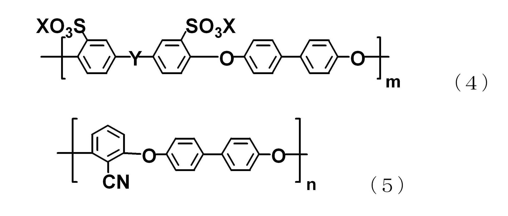
- the component represented by the general formula (2) preferably includes a component represented by the following general formula (4), and the component represented by the general formula (3) is represented by the following general formula (5). It is preferable that it is a structural component.
- X represents H or a monovalent cationic species. In the second invention of the present application, X represents sodium, potassium, or calcium.
- ion exchange membrane for vanadium redox battery of the present invention those containing the structural component represented by the general formula (5) together with the general formula (4) are particularly preferable.
- the dimensional stability in the electrolytic solution is excellent, and the toughness of the film is also high.
- the ion exchange membrane for vanadium redox battery of the present invention may contain structural units other than the above general formula (1) and the sulfonic acid group-containing component. At this time, it is preferable that structural units other than those represented by the general formula (1) are 50% by mass or less of the sulfonic acid group-containing component. By setting it to 50% by mass or less, the characteristics of the ion exchange membrane for vanadium redox battery of the present invention can be utilized.
- the sulfonic acid group content of the ion exchange membrane for vanadium redox battery of the present invention is a composition in the range of 25 ⁇ m ⁇ 55 and 45 ⁇ n ⁇ 75 in the above general formula (4) and general formula (5). Is preferred. When m is less than 25, there is a tendency that sufficient proton conductivity is not exhibited when used as a proton conductive membrane, and when m is greater than 55, the swellability and vanadium ion permeability to the electrolytic solution are poor. It tends to be too large to be suitable for use.
- sulfonic acid group content can be calculated
- the composition in which the A layer is in the range of 30 ⁇ m ⁇ 55 and the B layer is in the range of 23 ⁇ m ⁇ 30 is preferable.
- m of the A layer within the above range, a sufficiently low resistance can be exhibited when used as an ion exchange membrane for a vanadium redox battery.
- m is less than 30, the resistance tends to be high when used as an ion exchange membrane for a vanadium redox battery.
- m of the B layer within the above range, it is possible to suppress the transmission of divalent vanadium ions that are most easily transmitted among the vanadium ions. That is, when the B layer is disposed on the negative electrode side, the most excellent ion permeation suppressing effect can be expected.
- m is larger than 30, the swellability with respect to the electrolytic solution and the vanadium ion permeability become too large, and the current efficiency tends to be lowered.
- sulfonic acid group content can be calculated
- Both surfaces of the ion exchange membrane were used as an ion exchange membrane for a vanadium redox battery by increasing the electrolyte wettability of the surface of the ion exchange membrane by setting m of the A layer and the C layer within the above range. Sometimes a sufficiently low resistance can be exhibited. When m is less than 30, the resistance tends to be high when used as an ion exchange membrane for a vanadium redox battery. On the other hand, by setting m of the B layer within the above range, the central B layer can exhibit the vanadium ion permeation suppressing effect.
- the A layer satisfies 35 ⁇ m ⁇ 45, and the B layer satisfies 26 ⁇ m ⁇ 30.
- the ion exchange membrane for a vanadium redox battery of the present invention can be polymerized by an aromatic nucleophilic substitution reaction containing the compounds represented by the following general formula (6) and general formula (7) as monomers.
- Specific examples of the compound represented by the general formula (6) include 3,3′-disulfo-4,4′-dichlorodiphenyl sulfone, 3,3′-disulfo-4,4′-difluorodiphenyl sulfone, 3, 3'-disulfo-4,4'-dichlorodiphenyl ketone, 3,3'-disulfo-4,4'-difluorodiphenyl sulfone, and those whose sulfonic acid group is converted to a salt with a monovalent cationic species Can be mentioned.
- the monovalent cation species may be sodium, potassium, other metal species, various amines, or the like, but is not limited thereto.
- Examples of the compound represented by the general formula (7) include 2,6-dichlorobenzonitrile, 2,6-difluorobenzonitrile, 2,4-dichlorobenzonitrile, 2,4-difluorobenzonitrile, and 2,6-dichloro.
- Examples include benzamide and methyl 2,6-dichlorobenzoate.
- Y is a sulfonyl group or ketone group
- X is a monovalent cation species
- Z is chlorine or fluorine
- W is a monovalent or divalent group, and represents a nitrile group, an amide group, an ester group, or a carboxyl group.
- nitrile compounds are preferred.
- the above 2,6-dichlorobenzonitrile and 2,4-dichlorobenzonitrile are in an isomer relationship, and any of them has good ion conductivity, heat resistance, workability and dimensional stability. Can be achieved. The reason is considered that both monomers are excellent in reactivity and that the structure of the whole molecule is made harder by constituting a small repeating unit.
- various activated difluoroaromatic compounds and dichloroaromatic compounds can be used in combination with the compounds represented by the general formulas (6) and (7) as monomers.
- these compounds include 4,4′-dichlorodiphenylsulfone, 4,4′-difluorodiphenylsulfone, 4,4′-difluorobenzophenone, 4,4′-dichlorobenzophenone, decafluorobiphenyl, and the like.
- aromatic dihalogen compounds, aromatic dinitro compounds, aromatic dicyano compounds and the like that are active in aromatic nucleophilic substitution can also be used.
- Ar in the structural component represented by the general formula (1) and Ar ′ in the structural component represented by the general formula (2) are generally the same as those described above in the aromatic nucleophilic substitution polymerization. It is a structure introduced from an aromatic diol component monomer used together with the compounds represented by formulas (6) and (7).
- aromatic diol monomers include 4,4′-biphenol, bis (4-hydroxyphenyl) sulfone, 1,1-bis (4-hydroxyphenyl) ethane, 2,2-bis (4-hydroxy).
- aromatic diols that can be used for polymerization of polyarylene ether compounds by aromatic nucleophilic substitution reaction can also be used.
- a polymer can be obtained by reacting an aromatic compound and / or a dichloroaromatic compound with an aromatic diol in the presence of a basic compound.
- the polymerization can be carried out in a temperature range of 0 to 350 ° C., but a temperature of 50 to 250 ° C. is preferable. When the temperature is lower than 0 ° C., the reaction does not proceed sufficiently, and when the temperature is higher than 350 ° C., the polymer tends to be decomposed.
- the polymerization time is preferably 8 to 16 hours.
- the reaction can be carried out in the absence of a solvent, but is preferably carried out in a solvent.
- the solvent that can be used include N-methyl-2-pyrrolidone, N, N-dimethylacetamide, N, N-dimethylformamide, dimethyl sulfoxide, diphenyl sulfone, sulfolane, and the like.
- any solvent that can be used as a stable solvent in the aromatic nucleophilic substitution reaction may be used alone or as a mixture of two or more.
- Examples of the basic compound include sodium hydroxide, potassium hydroxide, sodium carbonate, potassium carbonate, sodium hydrogen carbonate, potassium hydrogen carbonate, and the like, and those that can convert an aromatic diol into an active phenoxide structure may be used. It can use without being limited to.
- water may be generated as a by-product.
- water can be removed from the system as an azeotrope by coexisting toluene or the like in the reaction system.
- a water absorbing material such as molecular sieve can also be used.
- the aromatic nucleophilic substitution reaction is carried out in a solvent
- the amount is less than 5% by mass, the degree of polymerization tends to be difficult to increase.
- the amount is more than 50% by mass, the viscosity of the reaction system becomes too high, and the post-treatment of the reaction product tends to be difficult.
- the solvent is removed from the reaction solution by evaporation, and the residue is washed as necessary to obtain the desired polymer.
- the polymer can be obtained by precipitating the polymer as a solid by adding the reaction solution in a solvent having low polymer solubility, and collecting the precipitate by filtration.
- the polymer or composition constituting the ion exchange membrane for a vanadium redox battery of the present invention may be a block polymer comprising the components of the above general formula (1) and general formula (2). It is preferable to use a block polymer because it has excellent dimensional stability in the electrolytic solution and improves the vanadium ion permeation suppression effect due to the microphase separation structure of the hydrophilic segment and the hydrophobic segment.
- the block polymer composed of the components of the general formula (1) and the general formula (2) can be synthesized by any known method. It can synthesize
- the terminal group of any of the oligomers that have been synthesized in advance and become hydrophilic and hydrophobic segments is modified with a highly reactive group such as the above-mentioned perfluoroaromatic compound such as decafluorobiphenyl.
- a highly reactive group such as the above-mentioned perfluoroaromatic compound such as decafluorobiphenyl.
- it can be synthesized by reacting the other oligomer.
- the oligomer may be used after being purified and isolated after synthesis, may be used as it is in the synthesized oligomer solution, or the purified and isolated oligomer may be used as a solution.
- the oligomer to be purified and isolated may be any oligomer, but the oligomer forming the hydrophobic segment is easier to synthesize.
- the other oligomer is preferably reacted in an equimolar amount, but in order to prevent gelation due to a side reaction during the reaction, it is preferable to keep the modified oligomer slightly in excess.
- the degree of excess varies depending on the molecular weight of the oligomer and the molecular weight of the target polymer, but is preferably in the range of 0.1 to 50 mol%, more preferably in the range of 0.5 to 10 mol%.
- the hydrophobic segment is preferably modified with a highly reactive group. Depending on the structure of the hydrophilic segment, the modification reaction may not proceed well.
- the polymer or composition constituting the ion exchange membrane for vanadium-based redox batteries has a polymer logarithmic viscosity measured by a method described later of 0.5 dl / g or more in each layer of a single layer or multiple layers. Is preferred.
- the logarithmic viscosity is more preferably 0.8 dl / g or more.
- problems in processability such as difficulty in dissolving the polymer occur, which is not preferable.
- polar organic solvents such as N-methylpyrrolidone and N, N-dimethylacetamide can be generally used. If the solubility is low, concentrated sulfuric acid is used. It can also be measured.
- the polymer or composition constituting the ion exchange membrane for vanadium redox batteries of the present invention may be a single polymer or a composition in combination with another polymer.
- these polymers include polyesters such as polyethylene terephthalate, polybutylene terephthalate, and polyethylene naphthalate, polyamides such as nylon 6, nylon 6,6, nylon 6,10, and nylon 12, polymethyl methacrylate, and polymethacrylate.
- Acrylate resins such as polymethyl acrylate, polyacrylic acid esters, polyacrylic acid resins, polymethacrylic acid resins, polyethylene, polypropylene, various polyolefins including polystyrene and diene polymers, polyurethane resins, cellulose acetate, Cellulosic resins such as ethyl cellulose, polyarylate, aramid, polycarbonate, polyphenylene sulfide, polyphenylene oxide, polysulfone, polyether Thermal curing of aromatic polymers such as sulfone, polyether ether ketone, polyether imide, polyimide, polyamide imide, polybenzimidazole, polybenzoxazole, polybenzthiazole, epoxy resin, phenol resin, novolac resin, benzoxazine resin There are no particular restrictions on the conductive resin.
- compositions with basic polymers such as polybenzimidazole and polyvinylpyridine are a preferred combination for improving polymer dimensionality. If a sulfonic acid group is further introduced into these basic polymers, the processability of the composition becomes more preferable.
- the sulfonic acid group-containing polyarylene ether compound of the present invention is preferably contained in an amount of 50% by mass or more and less than 100% by mass of the entire composition. More preferably, it is 70 mass% or more and less than 100 mass%.
- the content of the sulfonic acid group-containing polyarylene ether compound of the present invention is less than 50% by mass of the entire composition, the sulfonic acid group concentration of the ion exchange membrane containing the composition is lowered, and good ion conductivity is obtained.
- the unit containing a sulfonic acid group tends to be a discontinuous phase and the mobility of ions to be conducted tends to decrease.
- composition of the present invention if necessary, for example, an antioxidant, a heat stabilizer, a lubricant, a tackifier, a plasticizer, a crosslinking agent, a viscosity modifier, an antistatic agent, an antibacterial agent, an antifoaming agent, Various additives such as a dispersant and a polymerization inhibitor may be included.
- the ion exchange membrane of the third invention of the present application may include various reinforcing layers such as glass paper, glass cloth, ceramic nonwoven fabric, porous substrate, and nonwoven fabric as necessary.
- the polymer or composition constituting the ion exchange membrane for vanadium redox battery of the present invention can be formed into a molded body such as fiber or film by any method such as extrusion, spinning, rolling or casting. Among these, it is preferable to mold from a solution dissolved in an appropriate solvent.
- the solvent include aprotic polar solvents such as N, N-dimethylformamide, N, N-dimethylacetamide, dimethyl sulfoxide, N-methyl-2-pyrrolidone and hexamethylphosphonamide, and alcohols such as methanol and ethanol.
- An appropriate one can be selected, but is not limited thereto. A plurality of these solvents may be used as a mixture within a possible range.
- the concentration of the compound in the solution is preferably in the range of 0.1 to 50% by mass. If the compound concentration in the solution is less than 0.1% by mass, it tends to be difficult to obtain a good molded product, and if it exceeds 50% by mass, the workability tends to deteriorate.
- a method of obtaining a molded body from a solution can be performed using a conventionally known method.
- the molded product can be obtained by removing the solvent by heating, drying under reduced pressure, immersion in a compound non-solvent that can be mixed with a solvent that dissolves the compound, or the like.
- the solvent is an organic solvent
- the solvent is preferably distilled off by heating or drying under reduced pressure.
- the sulfonic acid group in the molded article thus obtained may contain a salt form with a cationic species, but it can be converted to a free sulfonic acid group by acid treatment as necessary. You can also.
- the method for laminating the ion exchange membrane in the third invention of the present application is not particularly limited, but it is preferable to perform lamination by adhesion or superposition.
- Overlaying refers to laminating a plurality of ion exchange membranes without using an adhesive or the like.
- Adhesion refers to bonding a plurality of ion exchange membranes with an adhesive ion exchange resin or the like, or solution casting in multiple layers.
- a plurality of ion exchange membranes may be superposed in a state where water or an organic solvent is included on the surface. In the case of bonding, it can be carried out by any known method such as overcoating by solution casting, solution casting in multiple layers, and heating press.
- the most preferable method for forming the ion exchange membrane of each layer is casting from a solution, and the solvent can be removed from the cast solution to obtain an ion exchange membrane for a vanadium redox battery.
- a hydrocarbon ion exchange membrane having a structure of two or more layers can be obtained by forming them by overlapping or bonding.
- the ion exchange membrane of the present invention is prepared from the sulfonic acid group-containing polyarylene ether compound or a composition thereof.
- the most preferable method for forming the ion exchange membrane is casting from a solution, and the solvent can be removed from the cast solution as described above to obtain an ion exchange membrane for a vanadium redox battery.
- a solvent using an organic polar solvent such as N-methyl-2-pyrrolidone, N, N-dimethylformamide, dimethyl sulfoxide, or an alcohol solvent may be used in some cases.
- the removal of the solvent is preferably by drying in view of the uniformity of the ion exchange membrane for vanadium redox batteries.
- the viscosity of the solution is high, when the substrate or the solution is heated and cast at a high temperature, the viscosity of the solution is lowered and the casting can be easily performed.
- the thickness of the solution at the time of casting is not particularly limited, but is preferably 10 to 1000 ⁇ m. More preferably, it is 50 to 500 ⁇ m.
- the thickness of the solution is less than 10 ⁇ m, the form as an ion exchange membrane for a vanadium redox battery tends to be not maintained, and if it is thicker than 1000 ⁇ m, a non-uniform ion exchange membrane tends to be easily formed.
- a method for controlling the cast thickness of the solution a known method can be used.
- the thickness can be controlled with the amount and concentration of the solution with a constant thickness using an applicator, a doctor blade, or the like, and with a cast area constant using a glass petri dish or the like.
- the cast solution can obtain a more uniform film by adjusting the solvent removal rate.
- the evaporation rate can be reduced by lowering the temperature in the first stage.
- the coagulation rate of the compound can be adjusted by leaving the solution in air or an inert gas for an appropriate time.
- the ion exchange membrane for vanadium-based redox batteries of the present invention can have any film thickness depending on the purpose, but is preferably as thin as possible from the viewpoint of ion conductivity. Specifically, in the first and second inventions of the present application, it is preferably 5 to 200 ⁇ m, more preferably 5 to 50 ⁇ m, and most preferably 5 to 20 ⁇ m.
- the thickness of each layer is preferably 5 to 200 ⁇ m, more preferably 5 to 50 ⁇ m, and most preferably 5 to 20 ⁇ m. If the thickness of the ion exchange membrane for a vanadium redox battery is less than 5 ⁇ m, it is difficult to handle the ion exchange membrane, and a short circuit or the like tends to occur when a vanadium redox battery is produced. The resistance value increases and the power generation performance of the vanadium redox battery tends to decrease.
- the sulfonic acid group in the membrane may contain a metal salt, but can be converted to free sulfonic acid by an appropriate acid treatment.
- the ion conductivity of the ion exchange membrane is preferably 1.0 ⁇ 10 ⁇ 3 S / cm or more.
- the ion conductivity is 1.0 ⁇ 10 ⁇ 3 S / cm or more, a good output tends to be obtained in a vanadium redox battery using the ion exchange membrane, which is less than 1.0 ⁇ 10 ⁇ 3 S / cm. In this case, the output of the vanadium redox battery tends to decrease.
- the IEC (ion exchange capacity) of the ion exchange membranes of the first and second inventions of the present application is 0.5 meq / g or more and preferably 3.0 meq / g or less. Furthermore, the IEC of the ion exchange membrane is 1.3 meq / g or more, and more preferably 2.1 meq / g. When the IEC of the ion exchange membrane is 0.5 meq / g or less, there is a tendency that sufficient proton conductivity is not exhibited when used as a proton conductive membrane.
- the IEC of the ion exchange membrane When the IEC of the ion exchange membrane is 3.0 meq / g or less, the swelling property and the vanadium ion permeability with respect to the electrolytic solution tend to be too large to be suitable for use.
- the IEC of the sulfonic acid group in each layer is 0.5 meq / g or more, and preferably 3.0 meq / g or less. Furthermore, the IEC of each layer is 1.3 meq / g or more, and more preferably 2.1 meq / g.
- the IEC of the ion exchange membrane When the IEC of the ion exchange membrane is 0.5 meq / g or less, there is a tendency that sufficient proton conductivity is not exhibited when the ion exchange membrane is used as a hydrocarbon ion exchange membrane having a structure of two or more layers. When the IEC of the ion exchange membrane is 3.0 meq / g or less, the swelling property and the vanadium ion permeability with respect to the electrolytic solution tend to be too large to be suitable for use.
- the difference in ion exchange capacity between layers having different ion exchange capacities is preferably 0.5 meq / g or more and 1.5 meq / g or less, more preferably 0.8 meq / g or more and 1.3 meq / g or less.
- the 3% weight reduction temperature of the ion exchange membrane of the present invention is preferably 300 ° C to 500 ° C. When the temperature is 300 ° C. or lower, durability may be insufficient when the temperature is increased.
- a vanadium redox battery is a battery that is charged and discharged by an oxidation-reduction reaction of vanadium having different valences.
- the ion exchange membrane is used as a diaphragm for adjusting the ion balance in the positive electrode and the negative electrode and preventing mixing of vanadium having different valences.
- the ion exchange membrane for a vanadium redox battery of the present invention may be used in a redox flow battery in which an aqueous electrolyte is charged and discharged by circulating a pump, or vanadium hydrate is used as a carbon electrode instead of an aqueous electrolyte. It may be used as a redox battery impregnated with.
- a redox flow battery that charges and discharges aqueous electrolyte solution by circulating a pump has a diaphragm disposed between a pair of current collector plates facing each other with a gap interposed therebetween, for example.
- An electrode material is sandwiched between at least one of the diaphragms, and the electrode material includes an electrolytic cell having a structure including an electrolytic solution made of an aqueous solution containing an active material.
- the aqueous electrolyte examples include iron-chromium, titanium-manganese-chromium, chromium-chromium, iron-titanium, etc., in addition to the vanadium electrolyte as described above, but the vanadium electrolyte is preferable.
- the carbon electrode material assembly of the present invention uses a vanadium-based electrolyte having a viscosity of 0.005 Pa ⁇ s or more at 25 ° C. or a vanadium-based electrolyte containing 1.5 mol / l or more of vanadium ions. Useful for redox flow batteries.
- Solution viscosity The polymer powder was dissolved in N-methylpyrrolidone at a concentration of 0.5 g / dl, and the viscosity was measured using a Ubbelohde viscometer in a constant temperature bath at 30 ° C., and the logarithmic viscosity ln [ta / tb] / Evaluation was made in c) (ta is the number of seconds that the sample solution was dropped, tb was the number of seconds that the solvent was dropped, and c was the polymer concentration).
- TGA thermogravimetry meter
- a small cell having an electrode area of 10 cm 2 of 10 cm in the vertical direction (liquid flow direction) and 1 cm in the width direction is formed, and charging and discharging are repeated at a constant current density, current efficiency, cell resistance, energy efficiency, voltage efficiency was calculated as follows. Moreover, 3 mol / l sulfuric acid aqueous solution of 2 mol / l vanadium oxysulfate was used for the positive electrode electrolyte, and 3 mol / l sulfuric acid aqueous solution of 2 mol / l vanadium sulfate was used for the negative electrode electrolyte. The amount of the electrolytic solution was excessively large with respect to the cell and the piping. The liquid flow rate was 6.2 ml per minute, and the measurement was performed at 30 ° C.
- the charging voltage V C50 and the discharging voltage V D50 corresponding to the amount of electricity when the charging rate is 50% are obtained from the amount of electricity-voltage curve, and the cell resistance R ( ⁇ ⁇ cm 2 ) with respect to the electrode geometric area is obtained from Equation 3. .
- E is a cell open circuit voltage of 1.432 V (measured value) when the charging rate is 50%
- I is a current value of 0.4 A in constant current charge / discharge.
- Equation 5 Energy efficiency: ⁇ E Using the current efficiency ⁇ I and the voltage efficiency ⁇ V described above, the energy efficiency ⁇ E is obtained by Equation 5.
- NMR measurement A polymer (sulfonic acid group is Na or K salt) was dissolved in a solvent, and 1 H-NMR was measured at room temperature using a UNITY-500 manufactured by VARIAN. Heavy dimethyl sulfoxide was used as the solvent. From the peak area value derived from the structural formula (4) and the peak area value derived from the structural formula (5), the molar ratio of the constituent components was calculated, and the values of m and n were calculated.
- Example 1 3,3′-disulfo-4,4′-dichlorodiphenylsulfone disodium salt (abbreviation: S-DCDPS) 5.000 g (0.01012 mole), 2,6-dichlorobenzonitrile (abbreviation: DCBN) 2.2215 g ( 0.01288 mole), 4,4'-biphenol 4.2846 g (0.02299 mole), potassium carbonate 3.4957 g (0.02529 mole) and 2.61 g of molecular sieves were weighed into a 100 ml four-necked flask and flushed with nitrogen. . After adding 30 ml of NMP and stirring at 150 ° C.
- Example 2 4.4560 g (0.00902 mole) of 3,3′-disulfo-4,4′-dichlorodiphenylsulfone disodium salt (abbreviation: S-DCDPS) and 3,6-dichlorobenzonitrile (abbreviation: DCBN) of 3.
- S-DCDPS 3,3′-disulfo-4,4′-dichlorodiphenylsulfone disodium salt
- DCBN 3,6-dichlorobenzonitrile
- the NMP solution of polymer 2 was cast on a glass plate on a hot plate with the thickness adjusted, and after NMP was distilled off until it became a film, it was immersed in water for more than one night to form a film with an average thickness of 30 ⁇ m. It was adjusted.
- the obtained film was treated in dilute sulfuric acid (concentrated sulfuric acid 6 ml, water 300 ml) for 1 hour to remove the salt, and then immersed in pure water for 1 hour to remove the acid component.
- the 3% weight loss temperature (measured based on the sample weight at 200 ° C.) by thermogravimetry of this film was 384 ° C.
- the IEC determined by titration was 1.70 meq / g.
- Example 3 The NMP solution of polymer 2 was cast on a glass plate on a hot plate with the thickness adjusted, and after NMP was distilled off until it became a film, it was immersed in water for more than one night to form a film with an average thickness of 30 ⁇ m. Prepared.
- S-DCDPS 3,3′-disulfo-4,4′-dichlorodiphenylsulfone disodium salt
- DCBN 4.6-dichlorobenz
- the IEC determined by titration was 2.03 meq / g and 1.33 meq / g, respectively.
- the produced ion exchange membranes of polymers 1 and 3 were superposed and sandwiched between carbon electrode materials (XF30A manufactured by Toyobo Co., Ltd.) to assemble a cell as shown in FIG.
- a small cell having an electrode area of 10 cm 2 of 10 cm in the vertical direction (liquid passing direction) and 1 cm in the width direction was prepared, and charge / discharge was repeated at a constant current density to evaluate the ion exchange membrane performance.
- a 3 mol / l sulfuric acid aqueous solution of 2 mol / l vanadium oxysulfate was used for the positive electrode electrolyte, and a 3 mol / l sulfuric acid aqueous solution of 2 mol / l vanadium sulfate was used for the negative electrode electrolyte.
- the amount of the electrolytic solution was excessively large with respect to the cell and the piping.
- the liquid flow rate was 6.2 ml per minute, and the measurement was performed at 30 ° C.
- Example 5 1 g of each of the polymer 3 and the polymer 2 was dissolved in 5 ml of NMP.
- the polymer 3 was cast on a glass plate on a hot plate to a thickness of about 80 ⁇ m, and after NMP was distilled off until it became a film, it was immersed in water overnight or more.
- Polymer 2 was cast on a glass plate on a hot plate to a thickness of about 200 ⁇ m, NMP was distilled off until it became a film, and then immersed in water overnight or longer.
- Each obtained film was treated with boiling water in dilute sulfuric acid (concentrated sulfuric acid 6 ml, water 300 ml) for 1 hour to remove the salt, converted to acid, and then boiled in pure water for 1 hour to liberate the acid component Removed and dried.
- the film thickness of polymer 3 was 10 ⁇ m, and the film thickness of polymer 2 was 30 ⁇ m.
- the 3% weight loss temperature (measured based on the sample weight at 200 ° C.) by thermogravimetry of this film was 389 ° C.
- the IEC determined by titration was 1.33 meq / g and 1.71 meq / g, respectively.
- the ion exchange membrane performance was evaluated in the same manner as in Example 4 except that the produced polymer 3 and 2 ion exchange membranes were superposed and sandwiched between carbon electrode materials (XF30A manufactured by Toyobo Co., Ltd.).
- Example 6 1 g of each of the obtained polymer 1 and polymer 3 was dissolved in 5 ml of NMP, and an NMP solution of polymer 1 was first cast on a glass plate on a hot plate to a thickness of about 200 ⁇ m, and NMP was distilled off until a film was formed. Further, an NMP solution of polymer 2 was cast to a thickness of 200 ⁇ m from above, and NMP was distilled off until a film was formed. Further, an NMP solution of polymer 1 was cast to a thickness of 200 ⁇ m from above, and NMP was distilled off until a film was formed. Thereafter, the NMP solution was immersed in water overnight or more and then dried. The obtained three-layer ion exchange membrane was assembled in the same manner as described above, and the performance was evaluated. The thickness of each layer was 10 ⁇ m.
- the ion exchange membranes produced in Examples 1 to 6 were sandwiched between carbon electrode materials (XF30A manufactured by Toyobo Co., Ltd.) to assemble a cell as shown in FIG. 10 cm 2 electrode area of 10 cm in the vertical direction (liquid passing direction) and 1 cm in the width direction A small cell having a constant current density is made, and charging / discharging is repeated at a constant current density to test the electrode performance.
- carbon electrode materials XF30A manufactured by Toyobo Co., Ltd.
- a 3 mol / l sulfuric acid aqueous solution of 2 mol / l vanadium oxysulfate was used for the positive electrode electrolyte, and a 3 mol / l sulfuric acid aqueous solution of 2 mol / l vanadium sulfate was used for the negative electrode electrolyte.
- the amount of the electrolytic solution was excessively large with respect to the cell and the piping.
- the liquid flow rate was 6.2 ml per minute, and the measurement was performed at 30 ° C.
- the ion exchange membrane of Example 1 had the lowest cell resistance and excellent voltage efficiency. Moreover, the ion exchange membrane of Example 2 also showed low cell resistance, and was excellent in voltage efficiency and energy efficiency.
- the ion exchange membrane of Example 3 was the most energy efficient in the single layer membrane. It was found that the ion exchange membranes composed of two or more layers of Examples 3 to 5 showed very high current efficiency, low resistance, and excellent energy efficiency. Thereby, it is thought that the deterioration of energy efficiency during charge / discharge cycles during long-term use can be suppressed.
- Comparative Example 1 was excellent in current efficiency, the cell efficiency was high, so that the voltage efficiency was lowered. Moreover, although the cell resistance of Comparative Example 2 was low as in Example 1, the current efficiency was lowered because the permeation suppression of vanadium ions was insufficient.
- the sulfonic acid group-containing aromatic polyarylene ether compound of the present invention as an ion exchange membrane for a redox battery, it is possible to provide a redox battery exhibiting a long life, low cell resistance, excellent voltage efficiency and energy efficiency. .
Abstract
Description

2.スルホン酸基を有するポリマーを含有してなるイオン交換膜であって、当該スルホン酸基が金属塩であることを特徴とするバナジウム系レドックス電池用イオン交換膜。
3.前記スルホン酸基を有するポリマーが、一般式(1)の構成成分を有し、前記金属塩がナトリウム塩、カリウム塩またはカルシウム塩であることを特徴とする2.に記載のバナジウム系レドックス電池用イオン交換膜。
2. An ion exchange membrane comprising a polymer having a sulfonic acid group, wherein the sulfonic acid group is a metal salt. An ion exchange membrane for a vanadium redox battery.
3. 1. The polymer having a sulfonic acid group has a constituent of the general formula (1), and the metal salt is a sodium salt, a potassium salt or a calcium salt. An ion exchange membrane for a vanadium redox battery as described in 1.

4.2層以上の構造からなり、各層にスルホン酸基を有するポリマーを含有してなるイオン交換膜であって、少なくともスルホン酸基含有量が異なる層を2層以上有するバナジウム系レドックス電池用イオン交換膜。
5.前記イオン交換膜において、スルホン酸基を有するポリマーが炭化水素系ポリマー及び/またはフッ素系ポリマーであることを特徴とする、4.に記載のバナジウム系レドックス電池用イオン交換膜。
6.前記イオン交換膜において、スルホン酸基を有する炭化水素系ポリマーが下記一般式(1)で表される構成成分を有することを特徴とする4.~5.のいずれかに記載のバナジウム系レドックス電池用イオン交換膜。
4. An ion-exchange membrane having a structure of two or more layers and containing a polymer having a sulfonic acid group in each layer, and at least two layers having different sulfonic acid group contents, an ion for vanadium redox battery Exchange membrane.
5. 3. In the ion exchange membrane, the polymer having a sulfonic acid group is a hydrocarbon polymer and / or a fluorine polymer. An ion exchange membrane for a vanadium redox battery as described in 1.
6). 3. In the ion exchange membrane, the hydrocarbon polymer having a sulfonic acid group has a constituent represented by the following general formula (1). ~ 5. The ion exchange membrane for vanadium redox batteries according to any one of the above.

7.前記スルホン酸基を含有する構成成分として、下記一般式(2)で示される構成成分を含むことを特徴とする1.~6.のいずれかに記載のバナジウム系レドックス電池用イオン交換膜。
7). 1. The structural component containing the sulfonic acid group includes a structural component represented by the following general formula (2). ~ 6. The ion exchange membrane for vanadium redox batteries according to any one of the above.

8.前記一般式(1)の構成成分が下記一般式(3)で示される構成成分であることを特徴とする1.3.6.7.のいずれかに記載のバナジウム系レドックス電池用イオン交換膜。
8). The structural component of the general formula (1) is a structural component represented by the following general formula (3) 1.3.6.7. The ion exchange membrane for vanadium redox batteries according to any one of the above.

9.前記スルホン酸基を含有するポリマーが前記一般式(2)の構成成分として下記一般式(4)で示される構成成分を含むとともに、前記一般式(3)の構成成分として下記一般式(5)で示される構成成分を含むことを特徴とする7.~8.のいずれかに記載のバナジウム系レドックス電池用イオン交換膜。
9. The polymer containing a sulfonic acid group contains a constituent represented by the following general formula (4) as a constituent of the general formula (2), and a constituent of the general formula (3) 6. It contains the component shown by 7. ~ 8. The ion exchange membrane for vanadium redox batteries according to any one of the above.

10.前記イオン交換膜が接着または重ね合わせによる2層以上のイオン交換膜の層からなることを特徴とする、4.~6.のいずれかに記載のバナジウム系レドックス電池用イオン交換膜。
11.N-メチル-2-ピロリドンを溶媒とした0.5g/dL溶液の30℃における単層または複層における各層の対数粘度が0.5~5.0dL/gである1.~10.のいずれかに記載のバナジウム系レドックス電池用イオン交換膜。
12.前記スルホン酸基を有するポリマーがポリアリーレンエーテル系化合物であり、該ポリマーを50~100質量%含むことを特徴とする1.~11.のいずれかに記載のバナジウム系レドックス電池用イオン交換膜。
13.1.~12.のいずれかに記載のイオン交換膜と、電極とを含有することを特徴とするバナジウム系レドックス電池用複合体。
14.13.に記載の複合体を含有することを特徴とするバナジウム系レドックス電池。
10. 3. The ion exchange membrane is composed of two or more ion exchange membrane layers bonded or superposed. ~ 6. The ion exchange membrane for vanadium redox batteries according to any one of the above.
11. 1. The logarithmic viscosity of each layer in a single layer or multiple layers at 30 ° C. of a 0.5 g / dL solution using N-methyl-2-pyrrolidone as a solvent is 0.5 to 5.0 dL / g. ~ 10. The ion exchange membrane for vanadium redox batteries according to any one of the above.
12 The polymer having a sulfonic acid group is a polyarylene ether compound and contains 50 to 100% by mass of the polymer. ~ 11. The ion exchange membrane for vanadium redox batteries according to any one of the above.
13.1. ~ 12. A composite for a vanadium redox battery, comprising the ion exchange membrane according to any one of the above and an electrode.
14.13. A vanadium redox battery comprising the composite described in 1.
本願第1~第3の発明は、イオン伝導性だけでなく耐熱性、加工性および寸法安定性に優れた、バナジウム系レドックス電池用イオン交換膜として有用な高分子材料を提供するものである。すなわち、ポリマー凝集効果のある極性基を有するジハロゲン化物またはその類似化合物を併用していることにより、極性基によるポリマー凝集効果から、バナジウムイオン透過性が低いイオン交換膜を提供することができる。また、電子吸引性の芳香環上にスルホン酸基を導入したモノマーとして、3,3’-ジスルホ-4,4‘-ジクロロジフェニルスルホン誘導体またはその類似化合物を用い、上記のポリアリーレンエーテルを合成することにより、高温でもスルホン酸基が脱離しにくいイオン交換膜を提供することができる。 Hereinafter, the present invention will be described in detail. The present invention comprises the first to third inventions of the present application described later, and unless otherwise noted, refers to matters common to the first to third inventions of the present application.
The first to third inventions of the present application provide a polymer material useful as an ion exchange membrane for a vanadium redox battery, which is excellent not only in ion conductivity but also in heat resistance, workability and dimensional stability. That is, by using a dihalide having a polar group having a polymer aggregating effect or a similar compound in combination, an ion exchange membrane having low vanadium ion permeability can be provided from the polymer aggregating effect by the polar group. Further, the above polyarylene ether is synthesized using 3,3′-disulfo-4,4′-dichlorodiphenylsulfone derivative or a similar compound as a monomer having a sulfonic acid group introduced on an electron-withdrawing aromatic ring. Thus, it is possible to provide an ion exchange membrane in which a sulfonic acid group is hardly detached even at a high temperature.
該スルホン酸基を有するポリマーは、炭化水素系ポリマー及び/またはフッ素系ポリマーであることが好ましい。前述のように、一般式(1)とともにスルホン酸基を含有する成分を含むポリマーを含有することが好ましい。 The third invention of the present application is an ion exchange membrane comprising a structure having two or more layers, each layer containing a polymer having a sulfonic acid group, and having at least two layers having different sulfonic acid group contents. It is an ion exchange membrane for a redox battery. By forming a hydrocarbon-based ion exchange membrane having different sulfonic acid group contents in each layer into a structure of two or more layers, an ion exchange membrane having further low vanadium ion permeability and membrane resistance can be provided. The ion exchange membrane preferably has a structure of 2 layers or more and 5 layers or less. If the number of layers is five or more, the preparation method of the ion exchange membrane may become difficult. More preferably, it has a structure of 2 to 3 layers.
The polymer having a sulfonic acid group is preferably a hydrocarbon polymer and / or a fluorine polymer. As described above, it is preferable to contain a polymer containing a component containing a sulfonic acid group together with the general formula (1).


各層のイオン交換膜を成形する手法として最も好ましいのは、溶液からのキャストであり、キャストした溶液から溶媒を除去してバナジウム系レドックス電池用イオン交換膜を得ることができる。それらを重ね合わせまたは接着などで形成させ、2層以上の構造からなる炭化水素系イオン交換膜を得ることができる。 The method for laminating the ion exchange membrane in the third invention of the present application is not particularly limited, but it is preferable to perform lamination by adhesion or superposition. Overlaying refers to laminating a plurality of ion exchange membranes without using an adhesive or the like. Adhesion refers to bonding a plurality of ion exchange membranes with an adhesive ion exchange resin or the like, or solution casting in multiple layers. When superposing, a plurality of ion exchange membranes may be superposed in a state where water or an organic solvent is included on the surface. In the case of bonding, it can be carried out by any known method such as overcoating by solution casting, solution casting in multiple layers, and heating press.
The most preferable method for forming the ion exchange membrane of each layer is casting from a solution, and the solvent can be removed from the cast solution to obtain an ion exchange membrane for a vanadium redox battery. A hydrocarbon ion exchange membrane having a structure of two or more layers can be obtained by forming them by overlapping or bonding.
充電に始まり、放電で終わる1サイクルのテストにおいて、電流密度を電極幾何面積当たり40mA/cm2(400mA)として、1.7Vまでの充電に要した電気量をQ1クーロン、1.0Vまでの定電流放電、およびこれに続く1.2Vでの定電圧放電で取りだした電気量をそれぞれQ2、Q3クーロンとし、数式1で電流効率ηI
を求める。 (A) Current efficiency: η I
In a one-cycle test starting with charging and ending with discharging, the current density is 40 mA / cm 2 (400 mA) per electrode geometric area, and the amount of electricity required for charging up to 1.7 V is constant up to Q 1 coulomb and 1.0 V. Let Q 2 and Q 3 coulomb be the amounts of electricity taken out by the current discharge and the subsequent constant voltage discharge at 1.2 V, respectively.
Ask for.

負極液中のV3+をV2+に完全に還元するのに必要な理論電気量Qthに対して、放電により取りだした電気量の比を充電率とし、数式2で充電率を求める。 (B) Cell resistance: R
The ratio of the amount of electricity taken out by discharge with respect to the theoretical amount of electricity Q th necessary to completely reduce V 3+ in the negative electrode solution to V 2+ is taken as the charging rate, and the charging rate is obtained by Equation 2.


上記の方法で求めたセル抵抗Rを用いて数式4の簡便法により電圧効率ηVを求める。 (C) Voltage efficiency: η V
Using the cell resistance R obtained by the above method, the voltage efficiency η V is obtained by the simple method of Equation 4.

前述の電流効率ηIと電圧効率ηVを用いて、数式5によりエネルギー効率ηEを求める。 (D) Energy efficiency: η E
Using the current efficiency η I and the voltage efficiency η V described above, the energy efficiency η E is obtained by

(a)、(b)、(c)、(d)の測定後、続いて同セルを用い、40mA/cm2の定電流密度でセル電圧1.0~1.7V間で充放電を繰り返し実施する。規定サイクル経過後、再び(a)、(b)、(c)、(d)の測定を行い、ηE及びその初期からの変化量ΔηEを求める。 (E) Change with time of charge / discharge cycle After measurement of (a), (b), (c), (d), the same cell was used and a cell voltage of 1.0 to 40 mA / cm 2 at a constant current density. Charging / discharging is repeated between 1.7V. After the prescribed cycle, the measurements (a), (b), (c), and (d) are performed again to obtain η E and the amount of change Δη E from the beginning.
イオン交換容量[meq/g]=(10-滴定量[ml])/2 IEC: 100 mg of the dried ion exchange membrane was immersed in 50 ml of 0.01N NaOH aqueous solution and stirred at 25 ° C. overnight. Then, neutralization titration with 0.05N HCl aqueous solution was performed. For neutralization titration, a potentiometric titrator COMMITE-980 manufactured by Hiranuma Sangyo Co., Ltd. was used. The ion exchange equivalent was calculated by the following formula.
Ion exchange capacity [meq / g] = (10-titer [ml]) / 2
3,3’-ジスルホ-4,4’-ジクロロジフェニルスルホン2ナトリウム塩(略号:S-DCDPS)5.000g(0.01012mole)、2,6-ジクロロベンゾニトリル(略号:DCBN)2.2215g(0.01288mole)、4,4’-ビフェノール4.2846g(0.02299mole)、炭酸カリウム3.4957g(0.02529mole)、モレキュラーシーブ2.61gを100ml四つ口フラスコに計り取り、窒素を流した。30mlのNMPを入れて、150℃で一時間撹拌した後、反応温度を195-200℃に上昇させて系の粘性が十分上がるのを目安に反応を続けた(約5時間)。放冷の後、沈降しているモレキュラーシーブを除いて水中にストランド状に沈殿させた。得られたポリマーは、沸騰水中で1時間洗浄した後、乾燥した。ポリマーの対数粘度は1.24dl/gを示し、上記構造式において、m=44、n=56であった。ポリマー構造式を下記に示す。下記をポリマー1と称する。 (Example 1)
3,3′-disulfo-4,4′-dichlorodiphenylsulfone disodium salt (abbreviation: S-DCDPS) 5.000 g (0.01012 mole), 2,6-dichlorobenzonitrile (abbreviation: DCBN) 2.2215 g ( 0.01288 mole), 4,4'-biphenol 4.2846 g (0.02299 mole), potassium carbonate 3.4957 g (0.02529 mole) and 2.61 g of molecular sieves were weighed into a 100 ml four-necked flask and flushed with nitrogen. . After adding 30 ml of NMP and stirring at 150 ° C. for 1 hour, the reaction was continued by raising the reaction temperature to 195-200 ° C. and sufficiently increasing the viscosity of the system (about 5 hours). After standing to cool, the precipitated molecular sieve was removed and the mixture was precipitated in water as a strand. The obtained polymer was washed in boiling water for 1 hour and then dried. The logarithmic viscosity of the polymer was 1.24 dl / g, and in the above structural formula, m = 44 and n = 56. The polymer structural formula is shown below. The following is referred to as

3,3’-ジスルホ-4,4’-ジクロロジフェニルスルホン2ナトリウム塩(略号:S-DCDPS)を4.4560g(0.00902mole)、2,6-ジクロロベンゾニトリル(略号:DCBN)を3.1583g(0.01831mole)、4,4’-ビフェノール5.0912g(0.02732mole)、炭酸カリウム4.1538g(0.03005mole)とする以外は、実施例1と同様にして重合を行い、上記構造式において、m=33、n=67のポリマーを得た。ポリマーの対数粘度は、1.58dl/gを示した。ポリマー構造式を下記に示す。下記をポリマー2と称する。 (Example 2)
4.4560 g (0.00902 mole) of 3,3′-disulfo-4,4′-dichlorodiphenylsulfone disodium salt (abbreviation: S-DCDPS) and 3,6-dichlorobenzonitrile (abbreviation: DCBN) of 3. Polymerization was conducted in the same manner as in Example 1 except that 1583 g (0.01831 mole), 4,4′-biphenol 5.0912 g (0.02732 mole), and potassium carbonate 4.1538 g (0.03005 mole). In the formula, a polymer with m = 33 and n = 67 was obtained. The logarithmic viscosity of the polymer was 1.58 dl / g. The polymer structural formula is shown below. The following is referred to as Polymer 2.

ポリマー2のNMP溶液を、ホットプレート上ガラス板に厚みを調節してキャストし、フィルム状になるまでNMPを留去した後、水中に一晩以上浸漬することで、厚さ平均30μmのフィルムを調製した。 (Example 3)
The NMP solution of polymer 2 was cast on a glass plate on a hot plate with the thickness adjusted, and after NMP was distilled off until it became a film, it was immersed in water for more than one night to form a film with an average thickness of 30 μm. Prepared.
3,3’-ジスルホ-4,4’-ジクロロジフェニルスルホン2ナトリウム塩(略号:S-DCDPS)を4.3220g(0.00875mole)、2,6-ジクロロベンゾニトリル(略号:DCBN)を4.1847g(0.02426mole)、4,4’-ビフェノール6.1494g(0.03300mole)、炭酸カリウム5.0171g(0.03630mole)とする以外は、実施例1と同様にして重合を行い、上記構造式において、m=26.5、n=73.5のポリマーを得た。ポリマーの対数粘度は、1.58dl/gを示した。ポリマー構造式を下記に示す。以下をポリマー3と称する。 (Example 4)
4.3220 g (0.00875 mole) of 3,3′-disulfo-4,4′-dichlorodiphenylsulfone disodium salt (abbreviation: S-DCDPS) and 4.6-dichlorobenzonitrile (abbreviation: DCBN) Polymerization was conducted in the same manner as in Example 1 except that 1847 g (0.02426 mole), 4,4′-biphenol 6.1494 g (0.03300 mole), and potassium carbonate 5.0171 g (0.03630 mole). In the formula, a polymer having m = 26.5 and n = 73.5 was obtained. The logarithmic viscosity of the polymer was 1.58 dl / g. The polymer structural formula is shown below. The following is referred to as

作製したポリマー1及び3のイオン交換膜を重ね合わせ、これを炭素電極材料(東洋紡社製XF30A)で挟み込み、図1で示したようなセルを組み立てた。上下方向(通液方向)に10cm、幅方向に1cmの電極面積10cm2 を有する小型のセルを作り、定電流密度で充放電を繰り返し、イオン交換膜性能の評価を行った。正極電解液には2mol/lのオキシ硫酸バナジウムの3mol/l硫酸水溶液を用い、負極電解液には2mol/lの硫酸バナジウムの3mol/l硫酸水溶液を用いた。電解液量はセル、配管に対して大過剰とした。液流量は毎分6.2mlとし、30℃で測定を行った。 About each of
The produced ion exchange membranes of
ポリマー3およびポリマー2について、それぞれ1gをNMP5mlに溶解し、ポリマー3はホットプレート上ガラス板に約80μm厚にキャストし、フィルム状になるまでNMPを留去した後、水中に一晩以上浸漬した。ポリマー2はホットプレート上ガラス板に約200μm厚にキャストし、フィルム状になるまでNMPを留去した後、水中に一晩以上浸漬した。得られたそれぞれのフィルムは、希硫酸(濃硫酸6ml、水300ml)中で1時間沸騰水処理して塩をはずし酸に変換した後、純水でさらに1時間煮沸することで遊離した酸成分を除去したに乾燥した。ポリマー3の膜厚みは10μm、ポリマー2の膜厚みは30μmであった。本フィルムの熱重量測定による3%重量減少温度(200℃での試料重量を基準にして測定)は389℃であった。滴定で求めたIECはそれぞれ1.33meq/g、1.71meq/gを示した。作製したポリマー3及び2のイオン交換膜を重ね合わせ、これを炭素電極材料(東洋紡社製XF30A)で挟み込んだ以外は、実施例4と同様にしてイオン交換膜性能を評価した。 (Example 5)
1 g of each of the
得られたポリマー1及びポリマー3について、それぞれ1gをNMP5mlに溶解し、最初にポリマー1のNMP溶液をホットプレート上ガラス板に約200μm厚にキャストし、フィルム状になるまでNMPを留去した。さらにその上からポリマー2のNMP溶液を200μm厚にキャストし、フィルム状になるまでNMPを留去した。さらにその上からポリマー1のNMP溶液を200μm厚にキャストし、フィルム状になるまでNMPを留去した後、水中に一晩以上浸漬し、その後乾燥した。得られた3層イオン交換膜を上記と同様にセルを組み立て、性能評価を行った。それぞれの層の厚さは10μmとした。 (Example 6)
1 g of each of the obtained
を有する小型のセルを作り、定電流密度で充放電を繰り返し、電極性能のテストを行う。正極電解液には2mol/lのオキシ硫酸バナジウムの3mol/l硫酸水溶液を用い、負極電解液には2mol/lの硫酸バナジウムの3mol/l硫酸水溶液を用いた。電解液量はセル、配管に対して大過剰とした。液流量は毎分6.2mlとし、30℃で測定を行った。 The ion exchange membranes produced in Examples 1 to 6 were sandwiched between carbon electrode materials (XF30A manufactured by Toyobo Co., Ltd.) to assemble a cell as shown in FIG. 10 cm 2 electrode area of 10 cm in the vertical direction (liquid passing direction) and 1 cm in the width direction
A small cell having a constant current density is made, and charging / discharging is repeated at a constant current density to test the electrode performance. A 3 mol / l sulfuric acid aqueous solution of 2 mol / l vanadium oxysulfate was used for the positive electrode electrolyte, and a 3 mol / l sulfuric acid aqueous solution of 2 mol / l vanadium sulfate was used for the negative electrode electrolyte. The amount of the electrolytic solution was excessively large with respect to the cell and the piping. The liquid flow rate was 6.2 ml per minute, and the measurement was performed at 30 ° C.

6…正極液タンク、7…負極液タンク、8,9…ポンプ DESCRIPTION OF
6 ... Cathode solution tank, 7 ... Cathode solution tank, 8, 9 ... Pump
Claims (14)
- 一般式(1)の構成成分とともにスルホン酸基を含有する構成成分を含むポリマーを含有することを特徴とするバナジウム系レドックス電池用イオン交換膜。

- スルホン酸基を有するポリマーを含有してなるイオン交換膜であって、当該スルホン酸基が金属塩であることを特徴とするバナジウム系レドックス電池用イオン交換膜。 An ion exchange membrane comprising a polymer having a sulfonic acid group, wherein the sulfonic acid group is a metal salt. An ion exchange membrane for a vanadium redox battery.
- 前記スルホン酸基を有するポリマーが、一般式(1)の構成成分を有し、前記金属塩がナトリウム塩、カリウム塩またはカルシウム塩であることを特徴とする請求項2に記載のバナジウム系レドックス電池用イオン交換膜。

- 2層以上の構造からなり、各層にスルホン酸基を有するポリマーを含有してなるイオン交換膜であって、少なくともスルホン酸基含有量が異なる層を2層以上有するバナジウム系レドックス電池用イオン交換膜。 An ion exchange membrane having a structure of two or more layers and containing a polymer having a sulfonic acid group in each layer, and having at least two layers having different sulfonic acid group contents, an ion exchange membrane for a vanadium redox battery .
- 前記イオン交換膜において、スルホン酸基を有するポリマーが炭化水素系ポリマー及び/またはフッ素系ポリマーであることを特徴とする、請求項4に記載のバナジウム系レドックス電池用イオン交換膜。 The ion exchange membrane for a vanadium redox battery according to claim 4, wherein the polymer having a sulfonic acid group in the ion exchange membrane is a hydrocarbon polymer and / or a fluorine polymer.
- 前記イオン交換膜において、スルホン酸基を有する炭化水素系ポリマーが下記一般式(1)で表される構成成分を有することを特徴とする請求項4~5のいずれかに記載のバナジウム系レドックス電池用イオン交換膜。

- 前記スルホン酸基を含有する構成成分として、下記一般式(2)で示される構成成分を含むことを特徴とする請求項1~6のいずれかに記載のバナジウム系レドックス電池用イオン交換膜。

- 前記一般式(1)の構成成分が下記一般式(3)で示される構成成分であることを特徴とする請求項1、3、6、7のいずれかに記載のバナジウム系レドックス電池用イオン交換膜。

- 前記スルホン酸基を含有するポリマーが前記一般式(2)の構成成分として下記一般式(4)で示される構成成分を含むとともに、前記一般式(3)の構成成分として下記一般式(5)で示される構成成分を含むことを特徴とする請求項7~8のいずれかに記載のバナジウム系レドックス電池用イオン交換膜。
- 前記イオン交換膜が接着または重ね合わせによる2層以上のイオン交換膜の層からなることを特徴とする、請求項4~6のいずれかに記載のバナジウム系レドックス電池用イオン交換膜。 The ion exchange membrane for a vanadium redox battery according to any one of claims 4 to 6, wherein the ion exchange membrane comprises two or more ion exchange membrane layers bonded or superposed.
- N-メチル-2-ピロリドンを溶媒とした0.5g/dL溶液の30℃における単層または複層における各層の対数粘度が0.5~5.0dL/gである請求項1~10のいずれかに記載のバナジウム系レドックス電池用イオン交換膜。 11. The logarithmic viscosity of each layer in a single layer or multiple layers at 30 ° C. of a 0.5 g / dL solution using N-methyl-2-pyrrolidone as a solvent is 0.5 to 5.0 dL / g. An ion exchange membrane for a vanadium redox battery according to claim 1.
- 前記スルホン酸基を有するポリマーがポリアリーレンエーテル系化合物であり、該ポリマーを50~100質量%含むことを特徴とする請求項1~11のいずれかに記載のバナジウム系レドックス電池用イオン交換膜。 The ion exchange membrane for vanadium redox battery according to any one of claims 1 to 11, wherein the polymer having a sulfonic acid group is a polyarylene ether compound and contains 50 to 100% by mass of the polymer.
- 請求項1~12のいずれかに記載のイオン交換膜と、電極とを含有することを特徴とするバナジウム系レドックス電池用複合体。 13. A vanadium redox battery composite comprising the ion exchange membrane according to claim 1 and an electrode.
- 請求項13に記載の複合体を含有することを特徴とするバナジウム系レドックス電池。 A vanadium redox battery comprising the composite according to claim 13.
Priority Applications (2)
| Application Number | Priority Date | Filing Date | Title |
|---|---|---|---|
| CN201280041024.0A CN103765650A (en) | 2011-08-22 | 2012-08-22 | Ion exchange membrane for vanadium redox batteries, composite body, and vanadium redox battery |
| EP12826021.3A EP2750233A4 (en) | 2011-08-22 | 2012-08-22 | Ion exchange membrane for vanadium redox batteries, composite body, and vanadium redox battery |
Applications Claiming Priority (6)
| Application Number | Priority Date | Filing Date | Title |
|---|---|---|---|
| JP2011-180351 | 2011-08-22 | ||
| JP2011180351 | 2011-08-22 | ||
| JP2012-080266 | 2012-03-30 | ||
| JP2012080266 | 2012-03-30 | ||
| JP2012113220 | 2012-05-17 | ||
| JP2012-113220 | 2012-05-17 |
Publications (1)
| Publication Number | Publication Date |
|---|---|
| WO2013027758A1 true WO2013027758A1 (en) | 2013-02-28 |
Family
ID=47746496
Family Applications (1)
| Application Number | Title | Priority Date | Filing Date |
|---|---|---|---|
| PCT/JP2012/071171 WO2013027758A1 (en) | 2011-08-22 | 2012-08-22 | Ion exchange membrane for vanadium redox batteries, composite body, and vanadium redox battery |
Country Status (4)
| Country | Link |
|---|---|
| EP (1) | EP2750233A4 (en) |
| JP (1) | JPWO2013027758A1 (en) |
| CN (1) | CN103765650A (en) |
| WO (1) | WO2013027758A1 (en) |
Cited By (7)
| Publication number | Priority date | Publication date | Assignee | Title |
|---|---|---|---|---|
| WO2014034415A1 (en) * | 2012-08-31 | 2014-03-06 | 東洋紡株式会社 | Ion exchange membrane for vanadium redox batteries, composite body, and vanadium redox battery |
| JP2016524280A (en) * | 2013-05-16 | 2016-08-12 | ユナイテッド テクノロジーズ コーポレイションUnited Technologies Corporation | Flow battery with hydrated ion exchange membrane with maximum water domain cluster size |
| JP2016534519A (en) * | 2013-10-18 | 2016-11-04 | エルジー・ケム・リミテッド | Ion transfer material, electrolyte membrane including the same, and method for producing the same |
| JP2017033895A (en) * | 2015-08-06 | 2017-02-09 | 東洋紡株式会社 | Diaphragm for redox battery |
| WO2017208943A1 (en) * | 2016-05-31 | 2017-12-07 | 株式会社ギャラキシー | Method for producing vanadium electrolytic solution |
| US10396385B2 (en) | 2017-03-31 | 2019-08-27 | Kolon Industries, Inc. | Ion exchanging membrane, method for manufacturing the same, and energy storage device comprising the same |
| CN111662446A (en) * | 2020-06-17 | 2020-09-15 | 福州大学 | Fluorine-containing polyarylether anion exchange membrane with low surface resistivity and high oxidation stability and preparation method thereof |
Families Citing this family (2)
| Publication number | Priority date | Publication date | Assignee | Title |
|---|---|---|---|---|
| IT201800004325A1 (en) * | 2018-04-09 | 2019-10-09 | Flow battery | |
| WO2023122050A1 (en) * | 2021-12-21 | 2023-06-29 | The Chemours Company Fc, Llc | Stretched multilayer cation exchange membranes |
Citations (11)
| Publication number | Priority date | Publication date | Assignee | Title |
|---|---|---|---|---|
| JPH0268146A (en) * | 1988-09-01 | 1990-03-07 | Asahi Glass Co Ltd | Anion exchanger having novel crosslinked structure |
| JPH06188005A (en) * | 1992-01-13 | 1994-07-08 | Kashimakita Kyodo Hatsuden Kk | Redox battery |
| JPH06271688A (en) * | 1993-03-19 | 1994-09-27 | Asahi Glass Co Ltd | Double-layered anion exchange membrane |
| JPH09223513A (en) * | 1996-02-19 | 1997-08-26 | Kashimakita Kyodo Hatsuden Kk | Liquid circulating type battery |
| JPH11502245A (en) | 1995-03-20 | 1999-02-23 | ヘキスト・アクチェンゲゼルシャフト | Polymer electrolyte and its manufacturing method |
| JP2003096219A (en) * | 2001-05-24 | 2003-04-03 | Asahi Glass Co Ltd | Anion exchange membrane |
| JP2003155361A (en) * | 2001-08-28 | 2003-05-27 | Asahi Glass Engineering Co Ltd | Method for producing anion exchange membrane |
| JP2004010631A (en) | 2002-06-03 | 2004-01-15 | Kanegafuchi Chem Ind Co Ltd | Polymer compound having protonic conductivity and polymer film having protonic conductivity |
| JP2009200030A (en) * | 2008-01-22 | 2009-09-03 | Toray Ind Inc | Method of manufacturing polymer electrolyte moldings, polymer electrolyte component, membrane electrode assembly, and polymer electrolyte fuel cell |
| JP2010031226A (en) * | 2008-06-26 | 2010-02-12 | Jsr Corp | Polyarylene-based copolymer and solid polyelectrolyte |
| JP2010170782A (en) * | 2009-01-21 | 2010-08-05 | Sharp Corp | Redox flow battery, and method of charging and discharging the same |
Family Cites Families (15)
| Publication number | Priority date | Publication date | Assignee | Title |
|---|---|---|---|---|
| AU2003273034A1 (en) * | 2002-10-17 | 2004-05-04 | Toyo Boseki Kabushiki Kaisha | Composite ion-exchange membrane |
| JP4720091B2 (en) * | 2004-02-27 | 2011-07-13 | 東洋紡績株式会社 | Ion exchange membrane |
| JP2005235404A (en) * | 2004-02-17 | 2005-09-02 | Toyobo Co Ltd | Blend ion exchange membrane, membrane/electrode joining body, and fuel cell |
| JP2005232202A (en) * | 2004-02-17 | 2005-09-02 | Toyobo Co Ltd | Multilayer ion-exchange membrane, membrane/electrode assembly and fuel cell |
| JP4697385B2 (en) * | 2004-02-26 | 2011-06-08 | 東洋紡績株式会社 | Ion exchange membrane, membrane / electrode assembly, fuel cell |
| JP5176261B2 (en) * | 2004-11-10 | 2013-04-03 | 東洋紡株式会社 | Direct methanol fuel cell |
| EP1826846A4 (en) * | 2004-11-10 | 2010-01-13 | Toyo Boseki | Aromatic hydrocarbon-base proton exchange membrane and direct methanol fuel cell using same |
| JP2007146111A (en) * | 2005-11-02 | 2007-06-14 | Toyobo Co Ltd | Sulfonic acid group-containing polymer, ion-exchange membrane, membrane/electrode assembly, fuel cell, and polymer composition |
| JP2008123974A (en) * | 2006-11-16 | 2008-05-29 | Toyobo Co Ltd | Polymer electrolyte membrane for fuel cell, and its application |
| JP2008138104A (en) * | 2006-12-04 | 2008-06-19 | Toyobo Co Ltd | Aromatic hydrocarbon-based ion exchange membrane and method for producing the same |
| JP2009217950A (en) * | 2008-03-07 | 2009-09-24 | Toyobo Co Ltd | Ion conductive polymer electrolyte membrane, and manufacturing method thereof |
| JP2009252480A (en) * | 2008-04-04 | 2009-10-29 | Toyobo Co Ltd | Ion-conducting polymer electrolyte membrane and its manufacturing method |
| WO2009136631A1 (en) * | 2008-05-08 | 2009-11-12 | 東洋紡績株式会社 | Novel sulfonic acid group-containing segmentalized block copolymer, use thereof, and method for producing novel block copolymer |
| JP2010108692A (en) * | 2008-10-29 | 2010-05-13 | Toyobo Co Ltd | Ion conductive polymer membrane |
| EP2447953A4 (en) * | 2009-06-24 | 2015-08-26 | Toyo Boseki | Solid polymer electrolyte composition, ion-exchange membrane, membrane electrode assembly, and fuel cell |
-
2012
- 2012-08-22 CN CN201280041024.0A patent/CN103765650A/en active Pending
- 2012-08-22 EP EP12826021.3A patent/EP2750233A4/en not_active Withdrawn
- 2012-08-22 WO PCT/JP2012/071171 patent/WO2013027758A1/en active Application Filing
- 2012-08-22 JP JP2012542714A patent/JPWO2013027758A1/en active Pending
Patent Citations (11)
| Publication number | Priority date | Publication date | Assignee | Title |
|---|---|---|---|---|
| JPH0268146A (en) * | 1988-09-01 | 1990-03-07 | Asahi Glass Co Ltd | Anion exchanger having novel crosslinked structure |
| JPH06188005A (en) * | 1992-01-13 | 1994-07-08 | Kashimakita Kyodo Hatsuden Kk | Redox battery |
| JPH06271688A (en) * | 1993-03-19 | 1994-09-27 | Asahi Glass Co Ltd | Double-layered anion exchange membrane |
| JPH11502245A (en) | 1995-03-20 | 1999-02-23 | ヘキスト・アクチェンゲゼルシャフト | Polymer electrolyte and its manufacturing method |
| JPH09223513A (en) * | 1996-02-19 | 1997-08-26 | Kashimakita Kyodo Hatsuden Kk | Liquid circulating type battery |
| JP2003096219A (en) * | 2001-05-24 | 2003-04-03 | Asahi Glass Co Ltd | Anion exchange membrane |
| JP2003155361A (en) * | 2001-08-28 | 2003-05-27 | Asahi Glass Engineering Co Ltd | Method for producing anion exchange membrane |
| JP2004010631A (en) | 2002-06-03 | 2004-01-15 | Kanegafuchi Chem Ind Co Ltd | Polymer compound having protonic conductivity and polymer film having protonic conductivity |
| JP2009200030A (en) * | 2008-01-22 | 2009-09-03 | Toray Ind Inc | Method of manufacturing polymer electrolyte moldings, polymer electrolyte component, membrane electrode assembly, and polymer electrolyte fuel cell |
| JP2010031226A (en) * | 2008-06-26 | 2010-02-12 | Jsr Corp | Polyarylene-based copolymer and solid polyelectrolyte |
| JP2010170782A (en) * | 2009-01-21 | 2010-08-05 | Sharp Corp | Redox flow battery, and method of charging and discharging the same |
Non-Patent Citations (2)
| Title |
|---|
| JOURNAL OF POWER SOURCES, (CHINA, vol. 195, 2011, pages 4380 - 4383 |
| See also references of EP2750233A4 * |
Cited By (9)
| Publication number | Priority date | Publication date | Assignee | Title |
|---|---|---|---|---|
| WO2014034415A1 (en) * | 2012-08-31 | 2014-03-06 | 東洋紡株式会社 | Ion exchange membrane for vanadium redox batteries, composite body, and vanadium redox battery |
| JP2016524280A (en) * | 2013-05-16 | 2016-08-12 | ユナイテッド テクノロジーズ コーポレイションUnited Technologies Corporation | Flow battery with hydrated ion exchange membrane with maximum water domain cluster size |
| JP2016534519A (en) * | 2013-10-18 | 2016-11-04 | エルジー・ケム・リミテッド | Ion transfer material, electrolyte membrane including the same, and method for producing the same |
| US9923225B2 (en) | 2013-10-18 | 2018-03-20 | Lg Chem, Ltd. | Ion transport material, electrolyte membrane comprising same, and method for producing same |
| JP2017033895A (en) * | 2015-08-06 | 2017-02-09 | 東洋紡株式会社 | Diaphragm for redox battery |
| WO2017208943A1 (en) * | 2016-05-31 | 2017-12-07 | 株式会社ギャラキシー | Method for producing vanadium electrolytic solution |
| JP6253859B1 (en) * | 2016-05-31 | 2017-12-27 | 株式会社ギャラキシー | Method for producing vanadium electrolyte |
| US10396385B2 (en) | 2017-03-31 | 2019-08-27 | Kolon Industries, Inc. | Ion exchanging membrane, method for manufacturing the same, and energy storage device comprising the same |
| CN111662446A (en) * | 2020-06-17 | 2020-09-15 | 福州大学 | Fluorine-containing polyarylether anion exchange membrane with low surface resistivity and high oxidation stability and preparation method thereof |
Also Published As
| Publication number | Publication date |
|---|---|
| EP2750233A1 (en) | 2014-07-02 |
| JPWO2013027758A1 (en) | 2015-03-19 |
| EP2750233A4 (en) | 2015-08-19 |
| CN103765650A (en) | 2014-04-30 |
Similar Documents
| Publication | Publication Date | Title |
|---|---|---|
| WO2013027758A1 (en) | Ion exchange membrane for vanadium redox batteries, composite body, and vanadium redox battery | |
| US9975995B2 (en) | Ion conducting polymer comprising partially branched block copolymer and use thereof | |
| JP3599041B2 (en) | Polymer electrolyte for polymer electrolyte fuel cell and fuel cell | |
| JP6447520B2 (en) | Ion exchange membrane for redox battery, composite, and redox battery | |
| WO2009136631A1 (en) | Novel sulfonic acid group-containing segmentalized block copolymer, use thereof, and method for producing novel block copolymer | |
| KR101911982B1 (en) | Block copolymer, manufacturing method therefor, and polymer electrolyte material, molded polymer electrolyte, and solid-polymer fuel cell using said block copolymer | |
| WO2014087957A1 (en) | Electrolyte-membrane assembly, membrane electrode assembly, fuel cell, water-electrolysis cell, and water-electrolysis device | |
| WO2011016444A1 (en) | Novel sulfonic acid group-containing segmented block copolymer and use thereof | |
| JP5905857B2 (en) | Polymer electrolyte, polymer electrolyte membrane, fuel cell catalyst layer binder, and use thereof | |
| WO2014034415A1 (en) | Ion exchange membrane for vanadium redox batteries, composite body, and vanadium redox battery | |
| JP2016207608A (en) | Ion exchange membrane for polybenzimidazole-based redox battery, method for producing the same, composite body, and redox battery | |
| JP2016192294A (en) | Ion exchange membrane for vanadium-based redox battery, complex and vanadium-based redox battery | |
| KR100968398B1 (en) | Polymeric laminates, processes for producing the same, and use thereof | |
| WO2014157389A1 (en) | Electrolyte membrane composition, solid polymer electrolyte membrane, method of producing said electrolyte membrane, membrane-electrode assembly, solid polymer-type fuel cell, and water electrolysis cell and water electrolysis apparatus | |
| JP4554568B2 (en) | Membrane-electrode structure for polymer electrolyte fuel cell | |
| JP4337038B2 (en) | Composition comprising an acidic group-containing polybenzimidazole compound | |
| JP2010232158A (en) | Proton conductive membrane and its manufacturing method, membrane-electrode assembly, and solid polymer fuel cell | |
| JP5412718B2 (en) | POLYMER ELECTROLYTE MOLDED MANUFACTURING METHOD, POLYMER ELECTROLYTE MATERIAL, POLYMER ELECTROLYTE COMPONENT, MEMBRANE ELECTRODE COMPOSITE AND POLYMER ELECTROLYTE FUEL CELL | |
| JP5581593B2 (en) | Polyarylene-based copolymer, proton conducting membrane and solid polymer electrolyte fuel cell | |
| JP5391779B2 (en) | Polymer electrolyte membrane and solid polymer electrolyte fuel cell | |
| JP2015228292A (en) | Solid polymer electrolyte membrane, membrane-electrode assembly, fuel battery, water electrolysis cell and water electrolysis device | |
| WO2007072978A1 (en) | Copolymer, polymer electrolyte and use thereof | |
| WO2021192949A1 (en) | Electrolyte membrane and redox flow battery using same | |
| JP2010135282A (en) | Proton conducting membrane and manufacturing method for same, membrane-electrode junction, and solid polymer type fuel cell | |
| JP4022833B2 (en) | Sulfonic acid group-containing polymer and use thereof |
Legal Events
| Date | Code | Title | Description |
|---|---|---|---|
| ENP | Entry into the national phase |
Ref document number: 2012542714 Country of ref document: JP Kind code of ref document: A |
|
| 121 | Ep: the epo has been informed by wipo that ep was designated in this application |
Ref document number: 12826021 Country of ref document: EP Kind code of ref document: A1 |
|
| NENP | Non-entry into the national phase |
Ref country code: DE |
|
| REEP | Request for entry into the european phase |
Ref document number: 2012826021 Country of ref document: EP |
|
| WWE | Wipo information: entry into national phase |
Ref document number: 2012826021 Country of ref document: EP |