WO2013024858A1 - Method for magnetic flaw detection and magnetic flaw detector - Google Patents
Method for magnetic flaw detection and magnetic flaw detector Download PDFInfo
- Publication number
- WO2013024858A1 WO2013024858A1 PCT/JP2012/070723 JP2012070723W WO2013024858A1 WO 2013024858 A1 WO2013024858 A1 WO 2013024858A1 JP 2012070723 W JP2012070723 W JP 2012070723W WO 2013024858 A1 WO2013024858 A1 WO 2013024858A1
- Authority
- WO
- WIPO (PCT)
- Prior art keywords
- flaw
- magnetic field
- flaw detection
- alternating current
- magnetic
- Prior art date
Links
Images


Classifications
-
- G—PHYSICS
- G01—MEASURING; TESTING
- G01N—INVESTIGATING OR ANALYSING MATERIALS BY DETERMINING THEIR CHEMICAL OR PHYSICAL PROPERTIES
- G01N27/00—Investigating or analysing materials by the use of electric, electrochemical, or magnetic means
- G01N27/72—Investigating or analysing materials by the use of electric, electrochemical, or magnetic means by investigating magnetic variables
- G01N27/82—Investigating or analysing materials by the use of electric, electrochemical, or magnetic means by investigating magnetic variables for investigating the presence of flaws
- G01N27/83—Investigating or analysing materials by the use of electric, electrochemical, or magnetic means by investigating magnetic variables for investigating the presence of flaws by investigating stray magnetic fields
-
- G—PHYSICS
- G01—MEASURING; TESTING
- G01N—INVESTIGATING OR ANALYSING MATERIALS BY DETERMINING THEIR CHEMICAL OR PHYSICAL PROPERTIES
- G01N27/00—Investigating or analysing materials by the use of electric, electrochemical, or magnetic means
- G01N27/72—Investigating or analysing materials by the use of electric, electrochemical, or magnetic means by investigating magnetic variables
- G01N27/82—Investigating or analysing materials by the use of electric, electrochemical, or magnetic means by investigating magnetic variables for investigating the presence of flaws
- G01N27/90—Investigating or analysing materials by the use of electric, electrochemical, or magnetic means by investigating magnetic variables for investigating the presence of flaws using eddy currents
- G01N27/9013—Arrangements for scanning
- G01N27/902—Arrangements for scanning by moving the sensors
Definitions
- the present invention when a flaw is formed by applying a magnetic field to a flaw detection material made of a magnetic material and there is a flaw that blocks the magnetic flux generated in the flaw detection material, the magnetic flux leaks to the surface space at the flaw-existing portion.
- the present invention relates to a magnetic flaw detection method and a magnetic flaw detection apparatus that utilize the above.
- the present invention solves the problem that the magnetizing means is enlarged when only the DC magnetic field is applied, and the problem that the flaw detection material generates heat when only the AC magnetic field is applied.
- the present invention relates to a magnetic flaw detection method and a magnetic flaw detection apparatus that can detect flaws with high accuracy by magnetizing a flaw detection material.
- a magnetic flaw detection method (leakage magnetic flux flaw detection method) is known as a method for nondestructively detecting a flaw existing in a flaw detection material such as a steel plate or a steel pipe.
- a flaw detection method when a flaw is formed by applying a magnetic field to a flaw detection material made of a magnetic material, if there is a flaw that blocks the magnetic flux generated in the flaw detection material, the magnetic flux is transferred to the surface space at the part where the flaw is present.
- This is a flaw detection method that utilizes the leakage to the surface.
- a direct current or alternating current electromagnet or coil is used as a magnetizing means for applying a magnetic field to a material to be detected, and a Hall element is used as a detecting means for detecting leakage magnetic flux from a flaw.
- a search coil or the like is used.
- Patent Literatures 1 and 2 have been proposed as devices for efficiently magnetically saturating a material to be detected using a magnetizing means such as an electromagnet or a coil.
- Patent Document 1 provides a magnetic pole and a flaw detection material by providing a brush-like yoke or a movable auxiliary yoke between a magnetic pole (yoke open end) and a flaw detection material (test material). The generation of leakage magnetic flux due to the gap is suppressed, and the magnetization efficiency is improved.
- the magnetic properties of the ferromagnetic material constituting the material to be inspected such as a steel plate and a steel pipe generally have non-linear properties represented by a hysteresis curve. For this reason, magnetizing until the magnetic flux density in the flaw detection material reaches about 1.4 T can be realized by applying a relatively small magnetic field.
- an extremely large magnetic field acts on the material to be inspected. It is necessary to let Further, in DC magnetic saturation, the magnetic flux is uniformly distributed in the thickness direction of the flaw detection material. For this reason, in order to magnetically saturate the material to be inspected using a DC electromagnet, a large magnetizing means corresponding to the size (thickness) of the material to be inspected is required.
- Patent Document 2 In order to solve the above problem, as described in Patent Document 2, it is only necessary to use a magnetizing means using an AC electromagnet and magnetize only the surface layer of the flaw detection material by utilizing the skin effect. According to the apparatus described in Patent Document 2, the size of the magnetizing means can be reduced. However, as described in Patent Document 2, when an inspection magnetic field is magnetized until an AC magnetic field is applied to reach a magnetic saturation state, since the heat generated by the eddy current generated in the inspection target material is large, leakage magnetic flux is detected. There arises a problem that adverse effects such as a decrease in sensitivity and a decrease in life of the detection means occur.
- the current flowing in the flaw detection material is accompanied by resistance heat generation and the flaw detection material is in a so-called induction heating state, it causes temperature fluctuations in the leakage magnetic flux detection means and its mounting jig provided in the periphery.
- sensors such as a Hall element, a search coil, and a flux gate are used as leakage flux detection means, and all of these affect the detection sensitivity and life of leakage flux due to temperature changes.
- An object of the present invention is to provide a magnetic flaw detection method and a magnetic flaw detection apparatus that can detect flaws with high accuracy by magnetizing a flaw detection material until the flaw detection material reaches a magnetic saturation state while solving the problem of heat generation.
- the purpose of applying a DC magnetic field is not to generate a magnetic flux leaking from a flaw, but to increase the magnetic flux density of the entire flaw detection material including the vicinity of the flaw to a substantially uniform magnetic flux density to a certain extent. It is.
- the present inventors have determined that the direction of the direct-current magnetic field to be applied is substantially the direction in which the path of the magnetic flux generated in the flaw detection material by the direct-current magnetic field is hardly obstructed by the flaw (that is, the direction in which the flaw extends). It was found that it was necessary to set a parallel direction).
- the purpose of applying an alternating magnetic field is to generate a leakage magnetic flux from a flaw.
- the present inventors have determined that the direction of the alternating magnetic field to be applied is substantially the direction in which the path of the magnetic flux generated in the flaw detection material by the alternating magnetic field is most likely to be hindered by the flaw (that is, the direction in which the flaw extends). It was found that the vertical direction is necessary.
- a DC bias magnetic field is applied substantially in parallel to the direction in which the detection target flaw extends, and an AC magnetic field is applied substantially perpendicularly to the direction in which the detection target flaw extends.
- an AC magnetic field is applied substantially perpendicularly to the direction in which the detection target flaw extends.
- a flaw to be detected is detected based on the leakage magnetic flux generated thereby.
- the magnetic flux density in the flaw detection material is likely to be relatively large by applying a DC bias magnetic field substantially parallel to the direction in which the detection target flaw (detection target flaw) extends.
- a DC bias magnetic field substantially parallel to the direction in which the detection target flaw (detection target flaw) extends.
- the detection target flaw detection target flaw
- by applying an AC magnetic field in addition to the bias magnetic field it is possible to relatively easily bring the material to be flawed into a magnetic saturation state, and the direction of the AC magnetic field to be applied is not subject to detection. Therefore, the leakage magnetic flux from the detection target flaw can be efficiently generated, and as a result, the detection target flaw can be detected with high accuracy.
- the flaw detection material is magnetized by applying a combination of a DC bias magnetic field and an AC magnetic field, so that the flaw detection material is made magnetic compared to the case where only the DC magnetic field is applied.
- the magnetizing means for saturation does not increase in size.
- the flaw detection material is magnetized by applying a combination of a DC bias magnetic field and an AC magnetic field, so that the flaw detection material is made magnetic compared to the case where only the AC magnetic field is applied and magnetized.
- the flaw detection material does not generate excessive heat even when saturated.
- the first invention of the present application described above is effective when the direction in which the detection target flaw extends is constant and the direction can be assumed in advance.
- a direction in which a DC bias magnetic field is applied (a direction substantially parallel to the flaw extending direction).
- the direction in which the alternating magnetic field is applied (direction substantially perpendicular to the direction in which the flaw extends) cannot be made constant.
- the flaw detection material can be magnetized to detect flaws with high accuracy.
- a rotating bias magnetic field excited by using an alternating current as an exciting current is applied to the flaw detection material, and the first alternating current having the same frequency as the alternating current and the first alternating current are applied.
- a rotating bias magnetic field excited by using an alternating current as an exciting current is applied to the flaw detection material.
- an alternating current is used as the exciting current for exciting the rotational bias magnetic field
- the frequency is set to a low frequency (for example, about 10 Hz to 2 kHz)
- the direct current bias magnetic field in the first invention of the present application described above is only in that direction. The behavior is the same as changing from moment to moment. For this reason, even with the rotational bias magnetic field of the second invention of the present application, flaws (flaws extending substantially parallel to the direction of the moment when the rotational bias magnetic field is present) are within a range where the magnetic flux density in the flaw detection material tends to be relatively large.
- a rotational alternating magnetic field whose phase is shifted by 90 ° from the rotational bias magnetic field (that is, the direction of the rotational bias magnetic field at a certain moment and the direction of the rotational alternating magnetic field are orthogonal to each other. ).
- This rotating AC magnetic field is a first AC current having the same frequency as the AC current that is the exciting current of the rotating bias magnetic field (if the frequency of the AC current that is the exciting current of the rotating bias magnetic field is low, the frequency of the first AC current is And a superposed alternating current superposed with a second alternating current having a frequency higher than that of the first alternating current (for example, about 1 kHz to 500 kHz) is used as the exciting current. Therefore, the alternating magnetic field generated by the high-frequency second alternating current predominantly acts on the flaw detection material, while the low-frequency first alternating current rotates the direction of the generated alternating magnetic field in the flaw detection material. To work for.
- the rotating AC magnetic field in the second invention of the present application shows the same behavior as the AC magnetic field in the first invention of the present application that changes only its direction from time to time.
- a rotating AC magnetic field whose phase is shifted by 90 ° from the rotating bias magnetic field is applied. Since the direction of the AC magnetic field is substantially perpendicular to the direction in which the above flaw (a flaw extending substantially in parallel with the instantaneous direction of the rotational bias magnetic field) extends, the leakage magnetic flux from the flaw can be efficiently generated. As a result, the above flaw can be detected with high accuracy.
- the bias magnetic field is rotated and the AC magnetic field is also rotated by shifting the phase of the bias magnetic field by 90 °, it is possible to detect flaws extending in various directions existing in the flaw detection material. Further, according to the present invention, the advantage that the magnetizing means for magnetically saturating the flaw detection material does not increase in size and the flaw detection material does not generate excessive heat even if the flaw detection material is magnetically saturated can be obtained. Is the same as in the first invention.
- the frequency of the first alternating current may be set in accordance with the relative moving speed of the magnetizing means that applies the rotating bias magnetic field and the rotating AC magnetic field with respect to the flaw detection material. Specifically, it is necessary to set the frequency of the first alternating current so that the rotational bias magnetic field and the rotational alternating magnetic field rotate at least once while the magnetizing means passes over the scratch. If the relative moving speed of the magnetizing means is increased, the frequency of the first alternating current needs to be set high, and accordingly, the frequency of the second alternating current that is a high frequency needs to be set high.
- the ratio between the frequency of the first alternating current and the frequency of the second alternating current is preferably set to a ratio (for example, 1:10 or more) that allows synchronous detection using the second alternating current as a reference signal.
- the present invention provides a first magnetizing means for applying a DC bias magnetic field substantially parallel to a direction in which a detection target flaw extends to a flaw detection material, and a detection target for the flaw detection material.
- Second magnetizing means for applying an alternating magnetic field substantially perpendicularly to the direction in which the flaw extends, and detecting means for detecting leakage magnetic flux generated by magnetizing the flaw detection material by the first magnetizing means and the second magnetizing means. It is also provided as a magnetic flaw detector characterized by comprising.
- the present invention provides a first rotating magnetization means for applying a rotational bias magnetic field excited by using an alternating current as an exciting current to the flaw detection material, and a flaw detection material.
- the excitation current is excited by using, as an excitation current, a superimposed alternating current obtained by superimposing a first alternating current having the same frequency as the alternating current and a second alternating current having a frequency higher than that of the first alternating current.
- the object while solving the problem that the magnetizing means is enlarged when only the DC magnetic field is applied, and the problem that the flaw detection material generates heat when only the AC magnetic field is applied, the object is covered until the magnetic saturation state is reached. It is possible to detect flaws with high accuracy by magnetizing the flaw detection material.
- FIG. 1 is a diagram showing a schematic configuration of the magnetic flaw detector according to the first embodiment of the present invention.
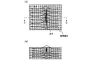
- FIG. 2 is a diagram schematically showing the state of magnetic flux in the flaw detection material when the direction of the DC magnetic field applied to the flaw detection material is substantially perpendicular to the direction in which the flaw extends.
- FIG. 3 is a diagram schematically showing the state of magnetic flux in the flaw detection material when the direction of the DC magnetic field applied to the flaw detection material is substantially parallel to the direction in which the flaw extends.
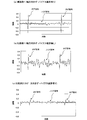
- FIG. 4 is a diagram showing test results of Example 1 and Comparative Examples 1 and 2 of the present invention.
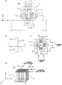
- FIG. 5 is a diagram showing a schematic configuration of a magnetic flaw detector according to the second embodiment of the present invention.
- FIG. 6 is a diagram schematically showing the relationship of the magnetic field generated by the magnetic flaw detector shown in FIG.
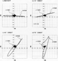
- FIG. 7 is a diagram showing test results of Example 2 of the present invention.
- the flaw detection material is a pipe, and a defect extending in the axial direction of the pipe (hereinafter referred to as an axial flaw) is a detection target.
- FIG. 1 is a diagram showing a schematic configuration of the magnetic flaw detector according to the first embodiment of the present invention.
- FIG. 1A shows an overall configuration diagram.
- FIG. 1B shows a schematic external view of the flaw detection probe shown in FIG.
- the magnetic flaw detection apparatus 100 according to the present embodiment extends in the direction in which an axial flaw F that is a detection target flaw extends in the pipe P (the axial direction of the pipe P (the X direction shown in FIG. 1)).
- First magnetizing means 1 for applying a DC bias magnetic field substantially parallel to the first magnetizing means, second magnetizing means 2 for applying an AC magnetic field substantially perpendicular to the direction in which the axial flaw F extends to the tube P, and first magnetizing means.
- a detecting means 3 for detecting a leakage magnetic flux generated by magnetizing the tube P with the first and second magnetizing means 2.
- the magnetic flaw detector 100 according to the present embodiment supplies the second magnetizing means 2 with an alternating current or performs signal processing on the flaw detection signal output from the detecting means 3 to detect the axial flaw F.
- Control means 4 is provided.
- 1st magnetization means 1 consists of a pair of penetration coils 1a and 1b which penetrate tube P.
- a direct current is supplied to each of the pair of through coils 1a and 1b, thereby generating a direct current magnetic field (bias magnetic field) A in a direction substantially parallel to the axial direction (X direction) of the tube P. That is, the direction of the bias magnetic field A is substantially parallel to the direction in which the axial flaw F extends.
- the second magnetizing means 2 is an air-core type tangential coil. This tangential coil is obtained by winding a conducting wire 22 around the core 21 made of a non-magnetic material in the axial direction (X direction) of the tube P. By supplying an alternating current from the arithmetic control means 4 to the conducting wire 22, an alternating magnetic field B is generated in a direction (Y direction shown in FIG. 1) substantially perpendicular to the axial direction (X direction) of the tube P. If the second magnetizing means 2 is arranged on the outer surface of the tube P, the generated AC magnetic field B travels along the circumferential direction of the tube P. That is, the direction of the alternating magnetic field B is substantially perpendicular to the direction in which the axial flaw F extends.
- the detection means 3 is a planar coil that detects leakage magnetic flux in the Z direction (see FIG. 1) that passes through the center of the second magnetization means (tangential coil) 2 and is orthogonal to the X direction and the Y direction.
- the detection means 3 is attached to the lower surface of the core 21 provided in the second magnetization means 2.
- the detection means 3 detects the leakage magnetic flux in the Z direction and outputs it to the arithmetic control means 4 as a flaw detection signal.
- the detection means 3 is integrated with the second magnetization means (tangential coil) 2 to form a flaw detection probe 20.
- the arithmetic control means 4 supplies an alternating current having a predetermined frequency to the second magnetization means (tangential coil) 2. Further, the arithmetic control unit 4 performs signal processing such as synchronous detection using the alternating current as a reference signal on the flaw detection signal output from the detection unit 3 to detect the axial flaw F.
- the magnetic flux density in the tube P becomes relatively large by applying a DC bias magnetic field A substantially parallel to the direction (X direction) in which the axial flaw F extends.
- a DC bias magnetic field A substantially parallel to the direction (X direction) in which the axial flaw F extends.
- FIG. 2 is a diagram schematically showing the state of magnetic flux in the flaw detection material when the direction of the DC magnetic field applied to the flaw detection material is substantially perpendicular to the direction in which the flaw extends.
- 2A is a plan view
- FIG. 2B is a cross-sectional view taken along the CC line in FIG.
- FIG. 3 is a diagram schematically showing the state of magnetic flux in the flaw detection material when the direction of the DC magnetic field applied to the flaw detection material is substantially parallel to the direction in which the flaw extends.
- 3A is a plan view
- FIG. 3B is a cross-sectional view taken along the arrow DD in FIG.
- the magnetic flux generated by applying the DC magnetic field (indicated by solid arrows in FIG. 2). ) Does not go straight to the immediate vicinity of the flaw and change its direction abruptly. For this reason, a region having a small magnetic flux density as shown by a broken line in FIG. 2 exists around the flaw. Therefore, especially in the vicinity of the flaw, the DC magnetic field does not function as a bias magnetic field for increasing the leakage magnetic flux from the flaw.
- the purpose of the DC magnetization is achieved to increase the magnetic flux density in the flaw detection material substantially uniformly. I can't.
- a direct-current bias magnetic field A is applied substantially parallel to the direction in which the axial flaw F extends (X direction). It is possible to magnetize the tube P substantially uniformly up to a range in which the magnetic flux density tends to be relatively large.
- an alternating magnetic field B is applied in addition to the bias magnetic field A.
- the tube P can be brought into a magnetic saturation state relatively easily, and the direction of the alternating magnetic field B to be applied is substantially perpendicular to the direction in which the axial flaw F extends, so that the leakage magnetic flux from the axial flaw F Can be generated efficiently.
- the axial flaw F can be detected with high accuracy.
- the tube P is magnetized by applying a combination of the bias magnetic field A and the alternating magnetic field B, so that it is compared with the case where only the direct magnetic field is applied for magnetization.
- the advantage that the magnetizing means for magnetically saturating the tube P is not increased is obtained.
- the tube P is magnetized by acting in combination with the bias magnetic field A and the alternating magnetic field B, so that it is compared with the case where the magnetic field is magnetized by acting only the alternating magnetic field.
- the advantage that the tube P does not generate excessive heat even when the tube P is magnetically saturated is also obtained.
- Example 1 In the present embodiment, a carbon steel pipe containing 0.25% by mass of carbon was used as the pipe P that is a flaw detection material. An artificial axial flaw having a depth of 0.5 mm and a length of 25 mm was provided on the surface of the tube P. Moreover, as the penetration coils 1a and 1b, which are the first magnetizing means 1, ones having 1000 turns, an outer diameter of 140 mm, an inner diameter of 80 mm, and a length (length along the axial direction of the tube P) of 50 mm are used.
- Each penetration coil 1a, 1b was arranged 40 mm apart in the axial direction of the pipe P.
- the current value of the direct current supplied to each through coil 1a, 1b was 1.5A, and it was possible to apply an appropriate bias magnetic field (magnetic flux density of about 1.5 T in the flaw detection material).
- the current value of the direct current required to magnetize to the extent that leakage flux flaw detection is possible with only the first magnetizing means 1 is about 9 A. Therefore, according to the present embodiment, it can be seen that flaw detection can be performed with a current value of about 1/6 as compared with the case where DC magnetic saturation is performed only by the first magnetization means 1.
- the second magnetizing means (tangential coil) 2 is obtained by winding 50 turns of the conducting wire 22 in the axial direction of the tube P around the core 21 made of a nonmagnetic cube having a side of 6 mm.
- the alternating current supplied to the conducting wire 22 had a frequency of 50 kHz and a current value of 200 mA. Those skilled in the art will recognize that this current value is very small compared to the value of the alternating current applied to the electromagnet used for normal AC magnetic flaw detection (magnetic flaw detection using only an AC magnetic field). Easy to understand.
- the second magnetizing means 2 of the present embodiment is used as the magnetizing means for generating the alternating magnetic field, it can be significantly reduced in size and weight as compared with the conventional electromagnet. This is a great advantage when the material to be inspected goes straight in the axial direction, and the magnetizing means for generating an alternating magnetic field rotates in the circumferential direction of the material to be inspected to detect the entire surface of the material to be inspected. . This is because if the second magnetizing means 2 of the present embodiment is used as the magnetizing means for generating an alternating magnetic field, the mechanism for rotating it in the circumferential direction of the material to be inspected can be reduced in size and simplified.
- a planar coil having a diameter of 5 mm and a turn number of 100 was used as the detection means 3.
- the flaw detection test was conducted under the above conditions.
- FIG. 4 is a diagram showing the test results of Example 1 and Comparative Examples 1 and 2.
- 4A shows the test result of Example 1
- FIG. 4B shows the test result of Comparative Example 1
- FIG. 4C shows the test result of Comparative Example 2.
- FIG. The waveform shown in FIG. 4 is obtained by synchronously detecting the flaw detection signal output from the detection means 3 using the alternating current supplied to the second magnetization means (tangential coil) 2 as a reference signal.
- Comparative Example 1 compared to Comparative Example 1 in which the bias magnetic field is not applied, in Comparative Example 2 in which the bias magnetic field is applied, in the noise signal
- the amplitude is decreasing.
- the amplitude of the flaw signal is smaller in Comparative Example 2 in which a bias magnetic field is applied. This is because the direction of the bias magnetic field is not parallel to the direction in which the bias magnetic field extends (forms an angle of 60 °), so there is a region where the magnetic flux density is small due to the detour of the magnetic flux around the flaw, and the magnetic saturation around the flaw The reason is thought to be that the level is lowered to prevent the generation of leakage magnetic flux from the flaw.
- FIG. 5 is a diagram showing a schematic configuration of a magnetic flaw detector according to the second embodiment of the present invention.
- Fig.5 (a) is a front view which shows the whole structure in a cross section partially.
- FIG. 5B is a plan view.
- FIG. 5C is a rear view.
- FIG. 5 (d) shows a schematic external view of the flaw detection probe shown in FIGS. 5 (a) to 5 (c). In FIG. 5B, the excitation coil is not shown.
- FIG. 5 shows a schematic configuration of a magnetic flaw detector according to the second embodiment of the present invention.
- Fig.5 (a) is a front view which shows the whole structure in a cross section partially.
- FIG. 5B is a plan view.
- FIG. 5C is a rear view.
- FIG. 5 (d) shows a schematic external view of the flaw detection probe shown in FIGS. 5 (a) to 5 (c).
- the excitation coil is not shown.
- the magnetic flaw detection apparatus 100 ′ includes a first rotation magnetization means 1 ′ that applies a rotation bias magnetic field to the tube P that is a flaw detection material, and the tube P. Leakage caused by magnetizing the tube P with the second rotating magnetizing means 2 ′ for applying a rotating AC magnetic field whose phase is shifted by 90 ° from the rotating bias magnetic field, and the first rotating magnetizing means 1 ′ and the second rotating magnetizing means 2 ′ And detecting means 3 for detecting magnetic flux.
- the magnetic flaw detection apparatus 100 ′ according to the present embodiment supplies an excitation current to the first rotation magnetization means 1 ′ and the second rotation magnetization means 2 ′ and performs signal processing on the flaw detection signal output from the detection means 3. Arithmetic control means 4 ′ for detecting an error is provided.
- the first rotating magnetization means 1 ′ is composed of a first electromagnet 11 and a second electromagnet 12 that intersects the first electromagnet 11.
- the first electromagnet 11 includes an inverted U-shaped yoke 111 and excitation coils 112 wound around both ends of the yoke 111.
- a magnetic field in a direction substantially parallel to the axial direction of the tube P (the X direction shown in FIG. 5) is provided between the magnetic poles 111a and 111b of the yoke 111. Generated.
- the second electromagnet 12 includes an inverted U-shaped yoke 121 and excitation coils 122 wound around both ends of the yoke 121.
- an alternating current from the arithmetic control means 4 ′ to the exciting coil 122
- X direction axial direction
- 121a and 121b of the yoke 121 the Y direction shown in FIG. 5
- the combined magnetic field generated by each excitation coil 112, 122 becomes the magnetic pole 111a, 111b, 121a, 121b. 360 degrees with respect to the center position.
- the first rotating magnetization unit 1 ′ applies a rotating bias magnetic field to the tube P.
- the second rotating magnetization means 2 ′ has the same configuration as the exciting coil described in Japanese Patent Application Laid-Open No. 2008-128733 proposed by the present inventors. Specifically, the second rotating magnetization means 2 ′ is formed of an air-core type tangential coil, like the second magnetization means 2 of the first embodiment. However, unlike the second magnetization means 2, the second rotational magnetization means 2 ′ not only winds the conductor 22 b around the core 21 made of a non-magnetic material in the axial direction (X direction) of the pipe P, but The conducting wire 22a is also wound in a direction (Y direction) substantially perpendicular to the axial direction of P.
- an excitation current (X direction excitation current) By supplying an excitation current (X direction excitation current) to the conducting wire 22a from the arithmetic control means 4 ′, an AC magnetic field in a direction substantially parallel to the axial direction (X direction) of the tube P is generated. Further, by supplying an excitation current (Y direction excitation current) from the arithmetic control means 4 'to the conducting wire 22b, an AC magnetic field in a direction (Y direction) substantially perpendicular to the axial direction (X direction) of the tube P is generated. Is done.
- the combined magnetic field of the alternating magnetic field generated by each of the conducting wires 22a and 22b is changed to that of the second rotating magnetization means 2 ′ (tangential coil). It will be rotated 360 ° around the center position. That is, a rotating AC magnetic field is generated.
- the second rotational magnetization means 2 ′ includes a first alternating current having the same frequency as the alternating current supplied to the first rotational magnetization means 1 ′ (supplied to the excitation coils 112 and 122), A superimposed alternating current obtained by superimposing a second alternating current having a frequency higher than that of the first alternating current is supplied as an exciting current from the arithmetic control unit 4 ′. More specifically, an X-direction excitation current obtained by superimposing the first alternating current and the second alternating current is supplied to the conducting wire 22a of the second rotating magnetization means 2 ′.
- the Y-direction exciting current whose first alternating current and second alternating current are superimposed and whose phase is shifted by 90 ° with respect to the X-direction exciting current is supplied to the conducting wire 22b of the second rotating magnetization means 2 ′. . Then, the X-direction excitation current and the Y-direction are set so that the phase of the rotating AC magnetic field generated by the second rotating magnetization unit 2 ′ is shifted by 90 ° from the phase of the rotating bias magnetic field generated by the first rotating magnetization unit 1 ′. The phase of the excitation current has been adjusted. As described above, the second rotating magnetization means 2 ′ applies a rotating AC magnetic field having a phase shifted by 90 ° from the rotating bias magnetic field to the tube P.
- the detection means 3 detects the leakage magnetic flux in the Z direction (see FIG. 5) passing through the center of the second rotational magnetization means (tangential coil) 2 ′ and orthogonal to the X direction and the Y direction. It is a planar coil.
- the detection means 3 is attached to the lower surface of the core 21 provided in the second rotational magnetization means 2 '.
- the detection means 3 detects the leakage magnetic flux in the Z direction and outputs it to the arithmetic control means 4 'as a flaw detection signal.
- the detection means 3 is integrated with the second rotary magnetization means (tangential coil) 2 'to form a flaw detection probe 20'.
- the arithmetic control unit 4 ′ supplies AC currents whose phases are shifted by 90 ° to the first electromagnet 11 and the second electromagnet 12 included in the first rotational magnetization unit 1 ′. Further, the arithmetic control means 4 ′ is a superimposed alternating current obtained by superimposing a first alternating current having the same frequency as the alternating current supplied to the first rotating magnetization means 1 ′ and a second alternating current having a higher frequency than the first alternating current. Superimposed alternating currents (X-direction excitation current and Y-direction excitation current) that are 90 ° out of phase with each other are supplied to the conducting wires 22a and 22b of the second rotating magnetization means 2 ′.
- the arithmetic control means 4 ′ is arranged so that the phase of the rotational bias magnetic field generated by the first rotational magnetization means 1 ′ and the phase of the rotational alternating magnetic field generated by the second rotational magnetization means 2 ′ are shifted by 90 °.
- the phases of the X-direction excitation current and the Y-direction excitation current supplied to the two-rotation magnetization means 2 ′ are adjusted.
- the arithmetic control unit 4 ′ performs signal processing such as synchronous detection using the second alternating current as a reference signal and synchronous detection using the first alternating current as a reference signal for the flaw detection signal output from the detecting unit 3.
- signal processing such as synchronous detection using the second alternating current as a reference signal and synchronous detection using the first alternating current as a reference signal for the flaw detection signal output from the detecting unit 3.
- FIG. 6 is a diagram schematically showing the relationship of the magnetic field generated by the magnetic flaw detector 100 ′ having the above configuration.
- a rotating bias magnetic field that is excited by using an alternating current as an exciting current acts on the tube P.
- an alternating current is used as an exciting current for exciting the rotational bias magnetic field, if the frequency is set to a low frequency, the direct current bias magnetic field generated by the magnetic flaw detector 100 according to the first embodiment described above is only in that direction. The behavior is the same as changing from moment to moment.
- a flaw (with the direction of the moment when the rotational bias magnetic field is present) is within a range in which the magnetic flux density in the tube P tends to be relatively large. It is possible to magnetize the tube P substantially uniformly without significantly disturbing the path of the magnetic flux by the flaw (flaw extending substantially in parallel).
- a rotational alternating magnetic field whose phase is shifted by 90 ° from the rotational bias magnetic field (that is, the direction and rotation of the rotational bias magnetic field at a certain moment).
- the direction of the AC magnetic field is orthogonal). This rotating AC magnetic field exhibits the same behavior as the AC magnetic field described in the first embodiment changes only its direction every moment.
- a rotating AC magnetic field that is 90 ° out of phase with the rotating bias magnetic field acts in addition to the rotating bias magnetic field, so that the tube P can be brought into a magnetic saturation state relatively easily.
- the direction of the rotating AC magnetic field to be applied is substantially perpendicular to the direction in which the flaw (a flaw extending substantially parallel to the direction of the moment when the rotation bias magnetic field is present) F, and therefore, the leakage magnetic flux from the flaw F As a result, the flaw F can be detected with high accuracy.
- the bias magnetic field is rotated, and the AC magnetic field is also rotated by shifting the phase of the bias magnetic field by 90 °, so that it is possible to detect flaws existing in the tube P extending in various directions. is there.
- the advantage that the magnetizing means for magnetically saturating the tube P does not increase in size, and the tube P does not generate excessive heat even when the tube P is magnetically saturated.
- the advantage is obtained as in the magnetic flaw detector 100 according to the first embodiment.
- Example 2 Also in this example, as in Example 1 described above, a carbon steel pipe containing 0.25 mass% carbon was used as the pipe P that is a flaw detection material.
- each exciting coil 112 provided in the first electromagnet 11 constituting the first rotating magnetization means 1 ′ one having 80 turns is used, and the alternating current supplied to each exciting coil 112 is: The current value was 10 A at a frequency of 100 Hz.
- each exciting coil 122 included in the second electromagnet 12 constituting the first rotating magnetization means 1 ′ one having 80 turns is used, and the alternating current supplied to each exciting coil 122 has a frequency of 100 Hz, The current value was 10A.
- the conductor 22b is wound 60 turns around the core 21 made of a non-magnetic cube having a side of 6 mm in the axial direction (X direction) of the tube P, A wire 22a wound 60 turns in a direction (Y direction) substantially perpendicular to the axial direction of the tube P was used.
- the 1st alternating current supplied to conducting wire 22a, 22b was made into the electric current value 200mA with the frequency of 100 Hz.
- the second alternating current supplied to the conducting wires 22a and 22b was set to a frequency of 20 kHz and a current value of 200 mA.
- a planar coil having a diameter of 5 mm and a turn number of 100 was used as the detection means 3.
- the flaw detection test was conducted under the above conditions.
- FIG. 7 is a diagram showing test results of Example 2.
- FIG. 7A shows the result of flaw detection in the axial direction
- FIG. 7B shows the result of flaw detection in the 15 ° direction
- FIG. 7C shows the result of flaw detection in the 45 ° direction.
- d) shows the result of flaw detection in a 75 ° direction flaw.
- the waveform shown in FIG. 7 is a Lissajous waveform created and displayed by the arithmetic control unit 4 ′ based on the flaw detection signal output from the detection unit 3.
- the arithmetic control unit 4 ′ performs synchronous detection of the flaw detection signal using the second alternating current (high frequency) supplied to the second rotational magnetization unit (tangential coil) 2 ′ as a reference signal, and then the second rotational magnetization unit (tangential coil).
- the first alternating current supplied to the coil) is synchronously detected as a reference signal (the signal obtained by synchronous detection is X signal), and the phase of the reference signal (first alternating current) is delayed by 90 ° to generate a flaw detection signal.
- Synchronous detection is performed (the Y signal is obtained by synchronous detection).
- the arithmetic control unit 4 ′ displays the signal as a vector on a two-dimensional plane of the XY coordinate system using the X signal as an X axis component and the Y signal as a Y axis component.
- This vector-displayed signal waveform is a Lissajous waveform.
Abstract
Description
特に、本発明は、直流磁界のみを作用させる場合に磁化手段が大型化する問題や、交流磁界のみを作用させる場合に被探傷材が発熱する問題を解決しつつ、磁気飽和状態になるまで被探傷材を磁化することにより、精度良くきずを検出可能な磁気探傷方法及び磁気探傷装置に関する。 According to the present invention, when a flaw is formed by applying a magnetic field to a flaw detection material made of a magnetic material and there is a flaw that blocks the magnetic flux generated in the flaw detection material, the magnetic flux leaks to the surface space at the flaw-existing portion. The present invention relates to a magnetic flaw detection method and a magnetic flaw detection apparatus that utilize the above.
In particular, the present invention solves the problem that the magnetizing means is enlarged when only the DC magnetic field is applied, and the problem that the flaw detection material generates heat when only the AC magnetic field is applied. The present invention relates to a magnetic flaw detection method and a magnetic flaw detection apparatus that can detect flaws with high accuracy by magnetizing a flaw detection material.
上記の着眼において、直流磁界を作用させる目的は、きずからの漏洩磁束を生じさせることではなく、きずの近傍を含む被探傷材全体の磁束密度を略均一に且つある程度の磁束密度まで増加させることである。本発明者らは、この目的に鑑みれば、作用させる直流磁界の方向は、直流磁界によって被探傷材中に発生する磁束の進路がきずによって最も妨げられにくい方向(すなわち、きずの延びる方向に略平行な方向)とする必要があることを知見した。
一方、上記の着眼において、交流磁界を作用させる目的は、きずからの漏洩磁束を生じさせることである。本発明者らは、この目的に鑑みれば、作用させる交流磁界の方向は、交流磁界によって被探傷材中に発生する磁束の進路がきずによって最も妨げられやすい方向(すなわち、きずの延びる方向に略垂直な方向)とする必要があることを知見した。 In order to solve the above-mentioned problems, the present inventors have conducted intensive studies. As a result, a direct-current magnetic field (bias magnetic field) is applied to a range where the magnetic flux density in the flaw detection material tends to be relatively large (about 1.4 T). In addition to being magnetized, by applying an alternating magnetic field to detect the leakage magnetic flux from the flawed material in a magnetic saturation state and further magnetizing it, it is possible to both reduce the size of the magnetizing means and prevent the flawed material from generating heat. We focused on whether we could solve the problem.
In the above viewpoint, the purpose of applying a DC magnetic field is not to generate a magnetic flux leaking from a flaw, but to increase the magnetic flux density of the entire flaw detection material including the vicinity of the flaw to a substantially uniform magnetic flux density to a certain extent. It is. In view of this object, the present inventors have determined that the direction of the direct-current magnetic field to be applied is substantially the direction in which the path of the magnetic flux generated in the flaw detection material by the direct-current magnetic field is hardly obstructed by the flaw (that is, the direction in which the flaw extends). It was found that it was necessary to set a parallel direction).
On the other hand, in the above viewpoint, the purpose of applying an alternating magnetic field is to generate a leakage magnetic flux from a flaw. In view of this object, the present inventors have determined that the direction of the alternating magnetic field to be applied is substantially the direction in which the path of the magnetic flux generated in the flaw detection material by the alternating magnetic field is most likely to be hindered by the flaw (that is, the direction in which the flaw extends). It was found that the vertical direction is necessary.
すなわち、本願の第1発明は、被探傷材に対して、検出対象きずの延びる方向に略平行に直流のバイアス磁界を作用させると共に、検出対象きずの延びる方向に略垂直に交流磁界を作用させ、これによって生ずる漏洩磁束に基づいて検出対象きずを検出することを特徴とする磁気探傷方法である。 The present invention has been completed based on the findings of the inventors as described above.
That is, according to the first invention of the present application, a DC bias magnetic field is applied substantially in parallel to the direction in which the detection target flaw extends, and an AC magnetic field is applied substantially perpendicularly to the direction in which the detection target flaw extends. In this magnetic flaw detection method, a flaw to be detected is detected based on the leakage magnetic flux generated thereby.
また、本発明によれば、直流のバイアス磁界と交流磁界とを組み合わせて作用させることにより被探傷材を磁化するため、直流磁界のみを作用させて磁化する場合に比べて、被探傷材を磁気飽和させるための磁化手段が大型化しないという利点が得られる。
さらに、本発明によれば、直流のバイアス磁界と交流磁界とを組み合わせて作用させることにより被探傷材を磁化するため、交流磁界のみを作用させて磁化する場合に比べて、被探傷材を磁気飽和させても被探傷材が過度に発熱しないという利点も得られる。 According to the first invention of the present application, the magnetic flux density in the flaw detection material is likely to be relatively large by applying a DC bias magnetic field substantially parallel to the direction in which the detection target flaw (detection target flaw) extends. Up to this point, it is possible to magnetize the material to be flawed substantially uniformly without significantly hindering the path of the magnetic flux by the flaws to be detected. According to the present invention, by applying an AC magnetic field in addition to the bias magnetic field, it is possible to relatively easily bring the material to be flawed into a magnetic saturation state, and the direction of the AC magnetic field to be applied is not subject to detection. Therefore, the leakage magnetic flux from the detection target flaw can be efficiently generated, and as a result, the detection target flaw can be detected with high accuracy.
In addition, according to the present invention, the flaw detection material is magnetized by applying a combination of a DC bias magnetic field and an AC magnetic field, so that the flaw detection material is made magnetic compared to the case where only the DC magnetic field is applied. There is an advantage that the magnetizing means for saturation does not increase in size.
Furthermore, according to the present invention, the flaw detection material is magnetized by applying a combination of a DC bias magnetic field and an AC magnetic field, so that the flaw detection material is made magnetic compared to the case where only the AC magnetic field is applied and magnetized. There is also an advantage that the flaw detection material does not generate excessive heat even when saturated.
そして、本発明によれば、上記回転バイアス磁界に加えて該回転バイアス磁界と位相が90°ずれた回転交流磁界(すなわち、ある瞬間の回転バイアス磁界の方向と回転交流磁界の方向とが直交する)を作用させる。この回転交流磁界は、回転バイアス磁界の励磁電流である交流電流と同一周波数の第1交流電流(回転バイアス磁界の励磁電流である交流電流の周波数を低周波とすれば、第1交流電流の周波数も低周波となる)と該第1交流電流よりも高周波の第2交流電流(例えば、1kHz~500kHz程度)とを重畳した重畳交流電流を励磁電流として用いることで励磁される。従って、高周波の第2交流電流によって生成される交流磁界が支配的に被探傷材に作用する一方、低周波の第1交流電流は、前記生成された交流磁界の方向を被探傷材において回転させるために機能する。これは、被探傷材に生じる誘導起電力が励磁電流の周波数に比例するからである。換言すれば、本願の第2発明における回転交流磁界は、前述した本願の第1発明における交流磁界がその方向だけを時々刻々変化させるのと同様の挙動を示すことになる。
本発明は、回転バイアス磁界に加えて該回転バイアス磁界と位相が90°ずれた回転交流磁界を作用させるため、被探傷材を比較的容易に磁気飽和状態にさせることができると共に、作用させる回転交流磁界の方向が上記のきず(回転バイアス磁界のある瞬間の方向と略平行に延びるきず)の延びる方向に略垂直となるため、上記のきずからの漏洩磁束を効率良く生じさせることができ、その結果、精度良く上記のきずを検出可能である。本発明は、バイアス磁界を回転させると共に、交流磁界もバイアス磁界と位相を90°ずらして回転させるため、被探傷材に存在する種々の方向に延びるきずを検出可能である。
また、本発明によれば、被探傷材を磁気飽和させるための磁化手段が大型化しないという利点や、被探傷材を磁気飽和させても被探傷材が過度に発熱しないという利点が得られることは、第1発明と同様である。 According to the second invention of the present application, a rotating bias magnetic field excited by using an alternating current as an exciting current is applied to the flaw detection material. Although an alternating current is used as the exciting current for exciting the rotational bias magnetic field, if the frequency is set to a low frequency (for example, about 10 Hz to 2 kHz), the direct current bias magnetic field in the first invention of the present application described above is only in that direction. The behavior is the same as changing from moment to moment. For this reason, even with the rotational bias magnetic field of the second invention of the present application, flaws (flaws extending substantially parallel to the direction of the moment when the rotational bias magnetic field is present) are within a range where the magnetic flux density in the flaw detection material tends to be relatively large. Therefore, it is possible to magnetize the material to be flawed substantially uniformly without greatly disturbing the path of the magnetic flux.
According to the present invention, in addition to the rotational bias magnetic field, a rotational alternating magnetic field whose phase is shifted by 90 ° from the rotational bias magnetic field (that is, the direction of the rotational bias magnetic field at a certain moment and the direction of the rotational alternating magnetic field are orthogonal to each other. ). This rotating AC magnetic field is a first AC current having the same frequency as the AC current that is the exciting current of the rotating bias magnetic field (if the frequency of the AC current that is the exciting current of the rotating bias magnetic field is low, the frequency of the first AC current is And a superposed alternating current superposed with a second alternating current having a frequency higher than that of the first alternating current (for example, about 1 kHz to 500 kHz) is used as the exciting current. Therefore, the alternating magnetic field generated by the high-frequency second alternating current predominantly acts on the flaw detection material, while the low-frequency first alternating current rotates the direction of the generated alternating magnetic field in the flaw detection material. To work for. This is because the induced electromotive force generated in the flaw detection material is proportional to the frequency of the excitation current. In other words, the rotating AC magnetic field in the second invention of the present application shows the same behavior as the AC magnetic field in the first invention of the present application that changes only its direction from time to time.
In the present invention, in addition to the rotating bias magnetic field, a rotating AC magnetic field whose phase is shifted by 90 ° from the rotating bias magnetic field is applied. Since the direction of the AC magnetic field is substantially perpendicular to the direction in which the above flaw (a flaw extending substantially in parallel with the instantaneous direction of the rotational bias magnetic field) extends, the leakage magnetic flux from the flaw can be efficiently generated. As a result, the above flaw can be detected with high accuracy. According to the present invention, since the bias magnetic field is rotated and the AC magnetic field is also rotated by shifting the phase of the bias magnetic field by 90 °, it is possible to detect flaws extending in various directions existing in the flaw detection material.
Further, according to the present invention, the advantage that the magnetizing means for magnetically saturating the flaw detection material does not increase in size and the flaw detection material does not generate excessive heat even if the flaw detection material is magnetically saturated can be obtained. Is the same as in the first invention.
本発明の第1実施形態に係る磁気探傷装置は、被探傷材が管であり、管の軸方向に延びるきず(以下、軸方向きずという)を検出対象とする。
図1は、本発明の第1実施形態に係る磁気探傷装置の概略構成を示す図である。図1(a)は、全体構成図を示す。また、図1(b)は、図1(a)に示す探傷プローブの模式的な外観図を示す。
図1に示すように、本実施形態に係る磁気探傷装置100は、管Pに対して検出対象きずである軸方向きずFの延びる方向(管Pの軸方向(図1に示すX方向))に略平行に直流のバイアス磁界を作用させる第1磁化手段1と、管Pに対して軸方向きずFの延びる方向に略垂直に交流磁界を作用させる第2磁化手段2と、第1磁化手段1及び第2磁化手段2で管Pを磁化することによって生ずる漏洩磁束を検出する検出手段3とを備えている。また、本実施形態に係る磁気探傷装置100は、第2磁化手段2に交流電流を供給したり、検出手段3から出力された探傷信号を信号処理して軸方向きずFを検出するための演算制御手段4を備えている。 <First Embodiment>
In the magnetic flaw detector according to the first embodiment of the present invention, the flaw detection material is a pipe, and a defect extending in the axial direction of the pipe (hereinafter referred to as an axial flaw) is a detection target.
FIG. 1 is a diagram showing a schematic configuration of the magnetic flaw detector according to the first embodiment of the present invention. FIG. 1A shows an overall configuration diagram. FIG. 1B shows a schematic external view of the flaw detection probe shown in FIG.
As shown in FIG. 1, the magnetic
図3は、被探傷材に作用させる直流磁界の方向がきずの延びる方向に対して略平行である場合の被探傷材中の磁束の状態を模式的に示す図である。図3(a)は平面図を、図3(b)は図3(a)のDD矢視断面図を示す。 FIG. 2 is a diagram schematically showing the state of magnetic flux in the flaw detection material when the direction of the DC magnetic field applied to the flaw detection material is substantially perpendicular to the direction in which the flaw extends. 2A is a plan view, and FIG. 2B is a cross-sectional view taken along the CC line in FIG.
FIG. 3 is a diagram schematically showing the state of magnetic flux in the flaw detection material when the direction of the DC magnetic field applied to the flaw detection material is substantially parallel to the direction in which the flaw extends. 3A is a plan view, and FIG. 3B is a cross-sectional view taken along the arrow DD in FIG.
<実施例1>
本実施例において、被探傷材である管Pとしては、0.25質量%の炭素を含有する炭素鋼管を用いた。この管Pの表面に、深さ0.5mmで長さ25mmの人工の軸方向きずを設けた。また、第1磁化手段1である貫通コイル1a、1bとしては、それぞれターン数1000で、外径140mm、内径80mm、長さ(管Pの軸方向に沿った長さ)50mmのものを用い、各貫通コイル1a、1bを管Pの軸方向に40mm隔てて配置した。各貫通コイル1a、1bに供給する直流電流の電流値は1.5Aとし、これにより、適正なバイアス磁界(被探傷材中の磁束密度約1.5T)を作用させることが可能であった。なお、この第1磁化手段1のみで漏洩磁束探傷が可能な程度にまで磁化する(被探傷材中の磁束密度約1.8T)のに必要な直流電流の電流値は約9Aである。従って、本実施例によれば、第1磁化手段1のみで直流磁気飽和させる場合に比べて、約1/6の電流値で探傷可能であることが分かる。 Hereinafter, an example of a flaw detection test using the magnetic
<Example 1>
In the present embodiment, a carbon steel pipe containing 0.25% by mass of carbon was used as the pipe P that is a flaw detection material. An artificial axial flaw having a depth of 0.5 mm and a length of 25 mm was provided on the surface of the tube P. Moreover, as the penetration coils 1a and 1b, which are the first magnetizing means 1, ones having 1000 turns, an outer diameter of 140 mm, an inner diameter of 80 mm, and a length (length along the axial direction of the tube P) of 50 mm are used. Each
以上の条件で探傷試験を行った。 Further, in the present embodiment, a planar coil having a diameter of 5 mm and a turn number of 100 was used as the detection means 3.
The flaw detection test was conducted under the above conditions.
第1磁化手段1によるバイアス磁界を作用させなかった点を除き、実施例と同様の条件で探傷試験を行った。 <Comparative Example 1>
A flaw detection test was performed under the same conditions as in the example except that the bias magnetic field by the first magnetization means 1 was not applied.
管軸方向に対して60°傾斜した方向に延びる人工きず(深さ及び長さは、実施例1と同様)を管Pの表面に設け、第2磁化手段(タンジェンシャルコイル)2によって生成される交流磁界の方向が上記人工きずの延びる方向と略垂直になるように第2磁化手段2の向きを調整した点を除き、実施例と同様の条件で探傷試験を行った。 <Comparative example 2>
An artificial flaw (depth and length is the same as in the first embodiment) extending in a direction inclined by 60 ° with respect to the tube axis direction is provided on the surface of the tube P, and is generated by the second magnetization means (tangential coil) 2. The flaw detection test was performed under the same conditions as in the example except that the direction of the second magnetizing means 2 was adjusted so that the direction of the alternating magnetic field to be generated was substantially perpendicular to the direction in which the artificial flaws extended.
図4は、実施例1及び比較例1、2の試験結果を示す図である。図4(a)は実施例1の試験結果を、図4(b)は比較例1の試験結果を、図4(c)は比較例2の試験結果を示す。図4に示す波形は、検出手段3から出力された探傷信号を、演算制御手段4が第2磁化手段(タンジェンシャルコイル)2に供給される交流電流を参照信号として同期検波したものである。 <Evaluation results>
FIG. 4 is a diagram showing the test results of Example 1 and Comparative Examples 1 and 2. 4A shows the test result of Example 1, FIG. 4B shows the test result of Comparative Example 1, and FIG. 4C shows the test result of Comparative Example 2. FIG. The waveform shown in FIG. 4 is obtained by synchronously detecting the flaw detection signal output from the detection means 3 using the alternating current supplied to the second magnetization means (tangential coil) 2 as a reference signal.
本発明の第2実施形態に係る磁気探傷装置は、被探傷材が管であり、種々の方向に延びるきずを検出対象とする。
図5は、本発明の第2実施形態に係る磁気探傷装置の概略構成を示す図である。図5(a)は、全体の構成を部分的に断面で示す正面図である。図5(b)は、平面図である。図5(c)は裏面図である。図5(d)は、図5(a)~(c)に示す探傷プローブの模式的な外観図を示す。なお、図5(b)においては、励磁コイルの図示を省略している。
図5に示すように、本実施形態に係る磁気探傷装置100’は、被探傷材である管Pに対して回転バイアス磁界を作用させる第1回転磁化手段1’と、管Pに対して前記回転バイアス磁界と位相が90°ずれた回転交流磁界を作用させる第2回転磁化手段2’と、第1回転磁化手段1’及び第2回転磁化手段2’で管Pを磁化することによって生ずる漏洩磁束を検出する検出手段3とを備えている。また、本実施形態に係る磁気探傷装置100’は、第1回転磁化手段1’や第2回転磁化手段2’に励磁電流を供給したり、検出手段3から出力された探傷信号を信号処理してきずを検出するための演算制御手段4’を備えている。 <Second Embodiment>
In the magnetic flaw detection apparatus according to the second embodiment of the present invention, the flaw detection material is a tube, and the detection target is a flaw extending in various directions.
FIG. 5 is a diagram showing a schematic configuration of a magnetic flaw detector according to the second embodiment of the present invention. Fig.5 (a) is a front view which shows the whole structure in a cross section partially. FIG. 5B is a plan view. FIG. 5C is a rear view. FIG. 5 (d) shows a schematic external view of the flaw detection probe shown in FIGS. 5 (a) to 5 (c). In FIG. 5B, the excitation coil is not shown.
As shown in FIG. 5, the magnetic
第1電磁石11は、逆U字状のヨーク111と、ヨーク111の両端部にそれぞれ巻回された励磁コイル112とを具備する。演算制御手段4’から励磁コイル112に交流電流を供給することにより、ヨーク111の磁極111a、111b間に管Pの軸方向(図5に示すX方向)に対して略平行な方向の磁界が生成される。
第2電磁石12は、逆U字状のヨーク121と、ヨーク121の両端部にそれぞれ巻回された励磁コイル122とを具備する。演算制御手段4’から励磁コイル122に交流電流を供給することにより、ヨーク121の磁極121a、121b間に管Pの軸方向(X方向)に対して略垂直な方向(図5に示すY方向)の磁界が生成される。
そして、各励磁コイル112、122に供給する交流電流(励磁電流)の位相を90°ずらすことにより、各励磁コイル112、122で生成された磁界の合成磁界が、磁極111a、111b、121a、121bの中心位置を中心として360°回転することになる。
以上のようにして、第1回転磁化手段1’は、管Pに対して回転バイアス磁界を作用させる。 The first rotating magnetization means 1 ′ is composed of a
The
The
Then, by shifting the phase of the alternating current (excitation current) supplied to each
As described above, the first
演算制御手段4’から導線22aに励磁電流(X方向励磁電流)を供給することにより、管Pの軸方向(X方向)に対して略平行な方向の交流磁界が生成される。
また、演算制御手段4’から導線22bに励磁電流(Y方向励磁電流)を供給することにより、管Pの軸方向(X方向)に対して略垂直な方向(Y方向)の交流磁界が生成される。
そして、各導線22a、22bに供給する励磁電流の位相を90°ずらすことにより、各導線22a、22bで生成された交流磁界の合成磁界が、第2回転磁化手段2’(タンジェンシャルコイル)の中心位置を中心として360°回転することになる。すなわち、回転交流磁界が生成される。 The second rotating magnetization means 2 ′ has the same configuration as the exciting coil described in Japanese Patent Application Laid-Open No. 2008-128733 proposed by the present inventors. Specifically, the second rotating magnetization means 2 ′ is formed of an air-core type tangential coil, like the second magnetization means 2 of the first embodiment. However, unlike the second magnetization means 2, the second rotational magnetization means 2 ′ not only winds the
By supplying an excitation current (X direction excitation current) to the
Further, by supplying an excitation current (Y direction excitation current) from the arithmetic control means 4 'to the
Then, by shifting the phase of the excitation current supplied to each of the conducting
一方、第2回転磁化手段2’の導線22bには、第1交流電流と第2交流電流とが重畳すると共にX方向励磁電流に対して位相が90°ずれたY方向励磁電流が供給される。
そして、第2回転磁化手段2’によって生成される回転交流磁界の位相が、第1回転磁化手段1’によって生成される回転バイアス磁界の位相と90°ずれるように、X方向励磁電流及びY方向励磁電流の位相が調整されている。
以上のようにして、第2回転磁化手段2’は、管Pに対して前記回転バイアス磁界と位相が90°ずれた回転交流磁界を作用させる。 Specifically, the second rotational magnetization means 2 ′ includes a first alternating current having the same frequency as the alternating current supplied to the first rotational magnetization means 1 ′ (supplied to the excitation coils 112 and 122), A superimposed alternating current obtained by superimposing a second alternating current having a frequency higher than that of the first alternating current is supplied as an exciting current from the
On the other hand, the Y-direction exciting current whose first alternating current and second alternating current are superimposed and whose phase is shifted by 90 ° with respect to the X-direction exciting current is supplied to the
Then, the X-direction excitation current and the Y-direction are set so that the phase of the rotating AC magnetic field generated by the second
As described above, the second rotating magnetization means 2 ′ applies a rotating AC magnetic field having a phase shifted by 90 ° from the rotating bias magnetic field to the tube P.
本実施形態に係る磁気探傷装置100’によれば、管Pに対して、交流電流を励磁電流として用いることで励磁される回転バイアス磁界が作用する。回転バイアス磁界を励磁する励磁電流としては交流電流を用いるものの、その周波数を低周波とすれば、あたかも前述した第1実施形態に係る磁気探傷装置100で生成される直流のバイアス磁界がその方向だけを時々刻々変化させるのと同様の挙動となる。このため、本実施形態に係る磁気探傷装置100’で生成される回転バイアス磁界によっても、管P中の磁束密度が比較的大きくなりやすい範囲までは、きず(回転バイアス磁界のある瞬間の方向と略平行に延びるきず)Fによって磁束の進路が大きく妨げられることなく、略均一に管Pを磁化することが可能である。 FIG. 6 is a diagram schematically showing the relationship of the magnetic field generated by the
According to the
<実施例2>
本実施例においても、前述した実施例1と同様に、被探傷材である管Pとして、0.25質量%の炭素を含有する炭素鋼管を用いた。この管Pの表面に、人工の軸方向きず、15°方向人工きず(管軸方向に対して15°傾斜した方向に延びる人工きず)、45°方向人工きず(管軸方向に対して45°傾斜した方向に延びる人工きず)、75°方向人工きず(管軸方向に対して75°傾斜した方向に延びる人工きず)を設けた。各人工きずは、いずれも深さ0.5mmで長さ25mmとした。 Hereinafter, an example of a flaw detection test using the magnetic
<Example 2>
Also in this example, as in Example 1 described above, a carbon steel pipe containing 0.25 mass% carbon was used as the pipe P that is a flaw detection material. Artificial axial flaws, 15 ° direction artificial flaws (artificial flaws extending in a direction inclined by 15 ° with respect to the tube axis direction), 45 ° direction artificial flaws (45 ° with respect to the tube axis direction) Artificial flaws extending in an inclined direction) and 75 ° direction artificial flaws (artificial flaws extending in a direction inclined by 75 ° with respect to the tube axis direction) were provided. Each artificial flaw had a depth of 0.5 mm and a length of 25 mm.
以上の条件で探傷試験を行った。 Further, in the present embodiment, a planar coil having a diameter of 5 mm and a turn number of 100 was used as the detection means 3.
The flaw detection test was conducted under the above conditions.
1’・・・第1回転磁化手段
2・・・第2磁化手段
2’・・・第2回転磁化手段
3・・・検出手段
4,4’・・・演算制御手段
20,20’・・・探傷プローブ
100,100’・・・磁気探傷装置
F・・・きず
P・・・管(被探傷材) DESCRIPTION OF
Claims (4)
- 被探傷材に対して、検出対象きずの延びる方向に略平行に直流のバイアス磁界を作用させると共に、検出対象きずの延びる方向に略垂直に交流磁界を作用させ、これによって生ずる漏洩磁束に基づいて検出対象きずを検出することを特徴とする磁気探傷方法。 A DC bias magnetic field is applied to the flaw detection material substantially parallel to the direction in which the detection target flaw extends, and an AC magnetic field is applied substantially perpendicular to the direction in which the detection target flaw extends. A magnetic flaw detection method characterized by detecting flaws to be detected.
- 被探傷材に対して、交流電流を励磁電流として用いることで励磁される回転バイアス磁界を作用させると共に、前記交流電流と同一周波数の第1交流電流と該第1交流電流よりも高周波の第2交流電流とを重畳した重畳交流電流を励磁電流として用いることで励磁され、前記回転バイアス磁界と位相が90°ずれた回転交流磁界を作用させ、これによって生ずる漏洩磁束に基づいてきずを検出することを特徴とする磁気探傷方法。 A rotating bias magnetic field excited by using an alternating current as an exciting current is applied to the flaw detection material, and a first alternating current having the same frequency as the alternating current and a second higher frequency than the first alternating current are applied. Excited by using a superimposed alternating current superimposed with an alternating current as an exciting current, and acting on a rotating alternating magnetic field whose phase is shifted by 90 ° from the rotational bias magnetic field, and detecting a defect based on a leakage magnetic flux generated thereby. Magnetic flaw detection method characterized by
- 被探傷材に対して検出対象きずの延びる方向に略平行に直流のバイアス磁界を作用させる第1磁化手段と、
被探傷材に対して検出対象きずの延びる方向に略垂直に交流磁界を作用させる第2磁化手段と、
前記第1磁化手段及び前記第2磁化手段で被探傷材を磁化することによって生ずる漏洩磁束を検出する検出手段と、
を備えることを特徴とする磁気探傷装置。 First magnetization means for applying a DC bias magnetic field substantially parallel to the direction in which the detection target flaw extends with respect to the flaw detection material;
A second magnetization means for applying an alternating magnetic field substantially perpendicularly to the direction in which the flaw to be detected extends with respect to the flaw detection material;
Detection means for detecting leakage magnetic flux generated by magnetizing the flaw detection material by the first magnetization means and the second magnetization means;
A magnetic flaw detector characterized by comprising: - 被探傷材に対して、交流電流を励磁電流として用いることで励磁される回転バイアス磁界を作用させる第1回転磁化手段と、
被探傷材に対して、前記交流電流と同一周波数の第1交流電流と該第1交流電流よりも高周波の第2交流電流とを重畳した重畳交流電流を励磁電流として用いることで励磁され、前記回転バイアス磁界と位相が90°ずれた回転交流磁界を作用させる第2回転磁化手段と、
前記第1回転磁化手段及び前記第2回転磁化手段で被探傷材を磁化することによって生ずる漏洩磁束を検出する検出手段と、
を備えることを特徴とする磁気探傷装置。 A first rotating magnetization means for applying a rotating bias magnetic field excited by using an alternating current as an exciting current to the flaw detection material;
The test object is excited by using a superimposed alternating current in which a first alternating current having the same frequency as the alternating current and a second alternating current having a frequency higher than the first alternating current are superimposed as an exciting current, A second rotating magnetization means for applying a rotating AC magnetic field whose phase is shifted by 90 ° from the rotating bias magnetic field;
Detecting means for detecting leakage magnetic flux generated by magnetizing the flaw detection material by the first rotating magnetization means and the second rotating magnetization means;
A magnetic flaw detector characterized by comprising:
Priority Applications (6)
| Application Number | Priority Date | Filing Date | Title |
|---|---|---|---|
| BR112013031968-2A BR112013031968B1 (en) | 2011-08-18 | 2012-08-15 | magnetic testing method and apparatus |
| CN201280040270.4A CN103733060B (en) | 2011-08-18 | 2012-08-15 | Magnetic method of detection and magnetic fault detector |
| JP2012537618A JP5201495B2 (en) | 2011-08-18 | 2012-08-15 | Magnetic flaw detection method and magnetic flaw detection apparatus |
| EP12823776.5A EP2746761B8 (en) | 2011-08-18 | 2012-08-15 | Method for magnetic flaw detection and magnetic flaw detector |
| US14/238,958 US9291599B2 (en) | 2011-08-18 | 2012-08-15 | Magnetic testing method and apparatus |
| CA2837283A CA2837283C (en) | 2011-08-18 | 2012-08-15 | Magnetic testing method and apparatus |
Applications Claiming Priority (2)
| Application Number | Priority Date | Filing Date | Title |
|---|---|---|---|
| JP2011178915 | 2011-08-18 | ||
| JP2011-178915 | 2011-08-18 |
Publications (1)
| Publication Number | Publication Date |
|---|---|
| WO2013024858A1 true WO2013024858A1 (en) | 2013-02-21 |
Family
ID=47715175
Family Applications (1)
| Application Number | Title | Priority Date | Filing Date |
|---|---|---|---|
| PCT/JP2012/070723 WO2013024858A1 (en) | 2011-08-18 | 2012-08-15 | Method for magnetic flaw detection and magnetic flaw detector |
Country Status (8)
| Country | Link |
|---|---|
| US (1) | US9291599B2 (en) |
| EP (1) | EP2746761B8 (en) |
| JP (1) | JP5201495B2 (en) |
| CN (1) | CN103733060B (en) |
| AR (1) | AR087581A1 (en) |
| BR (1) | BR112013031968B1 (en) |
| CA (1) | CA2837283C (en) |
| WO (1) | WO2013024858A1 (en) |
Cited By (5)
| Publication number | Priority date | Publication date | Assignee | Title |
|---|---|---|---|---|
| WO2017006589A1 (en) * | 2015-07-09 | 2017-01-12 | 株式会社日立ハイテクノロジーズ | Rail inspection device and rail inspection system |
| JP2017125709A (en) * | 2016-01-12 | 2017-07-20 | 新日鐵住金株式会社 | Magnetic leakage flux flaw detector |
| JP2017198572A (en) * | 2016-04-28 | 2017-11-02 | 株式会社東芝 | Magnetic characteristic measurement probe, magnetic characteristic measurement system, magnetic characteristic measurement method and degradation evaluation method |
| JP2019211292A (en) * | 2018-06-01 | 2019-12-12 | 富士電機株式会社 | Device for evaluating surface stress and/or hardness of magnetic substance |
| WO2022185998A1 (en) * | 2021-03-04 | 2022-09-09 | Tdk株式会社 | Detection device |
Families Citing this family (7)
| Publication number | Priority date | Publication date | Assignee | Title |
|---|---|---|---|---|
| KR101552922B1 (en) * | 2013-08-08 | 2015-09-15 | 매그나칩 반도체 유한회사 | Magnetic sensor test apparatus and method |
| WO2016143088A1 (en) * | 2015-03-11 | 2016-09-15 | 三菱電機株式会社 | Rope damage diagnostic examination device and rope damage diagnostic examination method |
| CN110234988B (en) * | 2017-01-26 | 2023-06-06 | 株式会社岛津制作所 | Magnetic body inspection device and magnetic body inspection method |
| CN107024534A (en) * | 2017-04-11 | 2017-08-08 | 北京工业大学 | The omni-directional vortex self-adapting scanning system of carbon fibre reinforced composite uniformity defect |
| EP3961203B1 (en) * | 2019-04-24 | 2022-11-30 | JFE Steel Corporation | Leakage magnetic flux flaw inspection device |
| FR3098915B1 (en) * | 2019-07-19 | 2022-07-29 | Framatome Sa | Magnetic flux leakage testing device and associated method |
| CN111157577A (en) * | 2020-02-13 | 2020-05-15 | 四川大学 | Steel pipe magnetization eddy current thermal imaging defect detection device |
Citations (7)
| Publication number | Priority date | Publication date | Assignee | Title |
|---|---|---|---|---|
| JPH0250676U (en) * | 1988-10-03 | 1990-04-09 | ||
| JPH07253412A (en) * | 1994-03-14 | 1995-10-03 | Nkk Corp | Magnetic powder flaw detector |
| JPH08152424A (en) | 1994-11-29 | 1996-06-11 | Mitsubishi Heavy Ind Ltd | Magnetizing head of leakage magnetic flux flaw-detecting device |
| JPH08304346A (en) * | 1995-05-10 | 1996-11-22 | Sumitomo Metal Ind Ltd | Magnetizer for leak magnetic flux flaw detection of circular sectional material |
| JP2001041932A (en) | 1999-07-27 | 2001-02-16 | Daido Steel Co Ltd | Leakage flux flaw detecting-apparatus and method for judging defect |
| JP2008128733A (en) | 2006-11-17 | 2008-06-05 | Sumitomo Metal Ind Ltd | Magnetic flaw detection method and magnetic flaw detecting device |
| JP2011002409A (en) * | 2009-06-22 | 2011-01-06 | Hara Denshi Sokki Kk | Leak flux flaw detecting device |
Family Cites Families (9)
| Publication number | Priority date | Publication date | Assignee | Title |
|---|---|---|---|---|
| US4602212A (en) * | 1982-06-14 | 1986-07-22 | Sumitomo Metal Industries, Ltd. | Method and apparatus including a flux leakage and eddy current sensor for detecting surface flaws in metal products |
| EP0228473B1 (en) * | 1985-07-03 | 1992-01-22 | Nippon Steel Corporation | Apparatus for non-destructively inspecting flaw of metal materials utilizing magnetic field |
| JPH0250676A (en) | 1988-08-12 | 1990-02-20 | Toshiba Corp | A/d processing clamp circuit |
| US5512821A (en) * | 1991-06-04 | 1996-04-30 | Nkk Corporation | Method and apparatus for magnetically detecting defects in an object with compensation for magnetic field shift by means of a compensating coil |
| US5491409A (en) * | 1992-11-09 | 1996-02-13 | The Babcock & Wilcox Company | Multiple yoke eddy current technique for detection of surface defects on metal components covered with marine growth |
| US6249119B1 (en) * | 1998-10-07 | 2001-06-19 | Ico, Inc. | Rotating electromagnetic field defect detection system for tubular goods |
| US7821258B2 (en) * | 2008-01-07 | 2010-10-26 | Ihi Southwest Technologies, Inc. | Method and system for generating and receiving torsional guided waves in a structure |
| DE102008020194A1 (en) * | 2008-04-16 | 2009-10-22 | Institut Dr. Foerster Gmbh & Co. Kg | Method and device for detecting near-surface defects by means of leakage flux measurement |
| JP4863127B2 (en) * | 2008-05-15 | 2012-01-25 | 住友金属工業株式会社 | Magnetic flaw detection method and magnetic flaw detection apparatus |
-
2012
- 2012-08-15 US US14/238,958 patent/US9291599B2/en active Active
- 2012-08-15 CA CA2837283A patent/CA2837283C/en not_active Expired - Fee Related
- 2012-08-15 WO PCT/JP2012/070723 patent/WO2013024858A1/en active Application Filing
- 2012-08-15 BR BR112013031968-2A patent/BR112013031968B1/en active IP Right Grant
- 2012-08-15 EP EP12823776.5A patent/EP2746761B8/en active Active
- 2012-08-15 CN CN201280040270.4A patent/CN103733060B/en not_active Expired - Fee Related
- 2012-08-15 JP JP2012537618A patent/JP5201495B2/en active Active
- 2012-08-16 AR ARP120103026A patent/AR087581A1/en active IP Right Grant
Patent Citations (7)
| Publication number | Priority date | Publication date | Assignee | Title |
|---|---|---|---|---|
| JPH0250676U (en) * | 1988-10-03 | 1990-04-09 | ||
| JPH07253412A (en) * | 1994-03-14 | 1995-10-03 | Nkk Corp | Magnetic powder flaw detector |
| JPH08152424A (en) | 1994-11-29 | 1996-06-11 | Mitsubishi Heavy Ind Ltd | Magnetizing head of leakage magnetic flux flaw-detecting device |
| JPH08304346A (en) * | 1995-05-10 | 1996-11-22 | Sumitomo Metal Ind Ltd | Magnetizer for leak magnetic flux flaw detection of circular sectional material |
| JP2001041932A (en) | 1999-07-27 | 2001-02-16 | Daido Steel Co Ltd | Leakage flux flaw detecting-apparatus and method for judging defect |
| JP2008128733A (en) | 2006-11-17 | 2008-06-05 | Sumitomo Metal Ind Ltd | Magnetic flaw detection method and magnetic flaw detecting device |
| JP2011002409A (en) * | 2009-06-22 | 2011-01-06 | Hara Denshi Sokki Kk | Leak flux flaw detecting device |
Cited By (7)
| Publication number | Priority date | Publication date | Assignee | Title |
|---|---|---|---|---|
| WO2017006589A1 (en) * | 2015-07-09 | 2017-01-12 | 株式会社日立ハイテクノロジーズ | Rail inspection device and rail inspection system |
| JP2017020862A (en) * | 2015-07-09 | 2017-01-26 | 株式会社日立ハイテクノロジーズ | Rail inspection system, and rail inspection system |
| US10591442B2 (en) | 2015-07-09 | 2020-03-17 | Hitachi High-Technologies Corporation | Rail check device and rail check system |
| JP2017125709A (en) * | 2016-01-12 | 2017-07-20 | 新日鐵住金株式会社 | Magnetic leakage flux flaw detector |
| JP2017198572A (en) * | 2016-04-28 | 2017-11-02 | 株式会社東芝 | Magnetic characteristic measurement probe, magnetic characteristic measurement system, magnetic characteristic measurement method and degradation evaluation method |
| JP2019211292A (en) * | 2018-06-01 | 2019-12-12 | 富士電機株式会社 | Device for evaluating surface stress and/or hardness of magnetic substance |
| WO2022185998A1 (en) * | 2021-03-04 | 2022-09-09 | Tdk株式会社 | Detection device |
Also Published As
| Publication number | Publication date |
|---|---|
| US9291599B2 (en) | 2016-03-22 |
| EP2746761A4 (en) | 2015-03-25 |
| CA2837283A1 (en) | 2013-02-21 |
| AR087581A1 (en) | 2014-04-03 |
| EP2746761B1 (en) | 2019-05-15 |
| CA2837283C (en) | 2017-07-18 |
| CN103733060B (en) | 2016-08-31 |
| CN103733060A (en) | 2014-04-16 |
| JPWO2013024858A1 (en) | 2015-03-05 |
| BR112013031968B1 (en) | 2020-11-03 |
| EP2746761B8 (en) | 2019-08-21 |
| JP5201495B2 (en) | 2013-06-05 |
| EP2746761A1 (en) | 2014-06-25 |
| BR112013031968A2 (en) | 2016-12-20 |
| US20140191751A1 (en) | 2014-07-10 |
Similar Documents
| Publication | Publication Date | Title |
|---|---|---|
| JP5201495B2 (en) | Magnetic flaw detection method and magnetic flaw detection apparatus | |
| JP4905560B2 (en) | Eddy current measurement sensor and inspection method using eddy current measurement sensor | |
| JP6060278B2 (en) | Apparatus and method for detecting internal defects in steel sheet | |
| JP6289732B2 (en) | Rope damage diagnostic inspection apparatus and rope damage diagnostic inspection method | |
| JP2013205024A (en) | Detector for non-destructive examination employing alternating field | |
| JP2012002705A (en) | Eddy current measuring sensor and eddy current measuring method | |
| JP2006177952A (en) | Eddy current probe, inspecting system and inspecting method | |
| JP2009204342A (en) | Eddy current type sample measurement method and eddy current sensor | |
| JP2011047736A (en) | Method of inspecting austenite-based stainless steel welding section | |
| JP2012093095A (en) | Nondestructive inspection system, and nondestructive inspection method | |
| JP2009002681A (en) | Magnetic measuring device provided with permanent magnet which performs periodic motion and oscillating coil | |
| JP2013170910A (en) | Carburization depth measuring method and device | |
| JP2014066688A (en) | Eddy current flaw detection probe, and eddy current flaw detection device | |
| JP5721475B2 (en) | Interpolation probe for eddy current testing of ferromagnetic steel tubes | |
| Horai et al. | Flux-focusing eddy current sensor with magnetic saturation for detection of water pipe defects | |
| JP2016197085A (en) | Magnetic flaw detection method | |
| JP4193181B2 (en) | Magnetizer for magnetic testing of steel pipes | |
| JP2009287981A (en) | Eddy-current flaw detector and eddy-current flaw detecting method | |
| JP5978661B2 (en) | Electromagnetic flaw detection probe | |
| JP2012184931A (en) | Method of measuring fraction of structure in steel plate | |
| RU103926U1 (en) | ELECTROMAGNETIC CONVERTER TO DEFECTOSCOPE | |
| RU2672978C1 (en) | Method for detecting defects in a long-dimensional ferromagnetic object | |
| JP5134997B2 (en) | Eddy current flaw detection probe, eddy current flaw detection apparatus, and eddy current flaw detection method | |
| JP2002082095A (en) | Flaw detector for steel bar | |
| WO2020032040A1 (en) | Eddy current flaw detection device and eddy current flaw detection method |
Legal Events
| Date | Code | Title | Description |
|---|---|---|---|
| ENP | Entry into the national phase |
Ref document number: 2012537618 Country of ref document: JP Kind code of ref document: A |
|
| 121 | Ep: the epo has been informed by wipo that ep was designated in this application |
Ref document number: 12823776 Country of ref document: EP Kind code of ref document: A1 |
|
| ENP | Entry into the national phase |
Ref document number: 2837283 Country of ref document: CA |
|
| WWE | Wipo information: entry into national phase |
Ref document number: 2012823776 Country of ref document: EP |
|
| WWE | Wipo information: entry into national phase |
Ref document number: 14238958 Country of ref document: US |
|
| NENP | Non-entry into the national phase |
Ref country code: DE |
|
| REG | Reference to national code |
Ref country code: BR Ref legal event code: B01A Ref document number: 112013031968 Country of ref document: BR |
|
| ENP | Entry into the national phase |
Ref document number: 112013031968 Country of ref document: BR Kind code of ref document: A2 Effective date: 20131212 |