WO2013024563A1 - 情報処理装置及び情報処理方法 - Google Patents
情報処理装置及び情報処理方法 Download PDFInfo
- Publication number
- WO2013024563A1 WO2013024563A1 PCT/JP2012/004479 JP2012004479W WO2013024563A1 WO 2013024563 A1 WO2013024563 A1 WO 2013024563A1 JP 2012004479 W JP2012004479 W JP 2012004479W WO 2013024563 A1 WO2013024563 A1 WO 2013024563A1
- Authority
- WO
- WIPO (PCT)
- Prior art keywords
- image
- information
- output
- resolution
- recording
- Prior art date
- Legal status (The legal status is an assumption and is not a legal conclusion. Google has not performed a legal analysis and makes no representation as to the accuracy of the status listed.)
- Ceased
Links
Images


Classifications
-
- G—PHYSICS
- G06—COMPUTING OR CALCULATING; COUNTING
- G06T—IMAGE DATA PROCESSING OR GENERATION, IN GENERAL
- G06T11/00—Two-dimensional [2D] image generation
- G06T11/60—Creating or editing images; Combining images with text
-
- G—PHYSICS
- G06—COMPUTING OR CALCULATING; COUNTING
- G06F—ELECTRIC DIGITAL DATA PROCESSING
- G06F3/00—Input arrangements for transferring data to be processed into a form capable of being handled by the computer; Output arrangements for transferring data from processing unit to output unit, e.g. interface arrangements
- G06F3/01—Input arrangements or combined input and output arrangements for interaction between user and computer
- G06F3/048—Interaction techniques based on graphical user interfaces [GUI]
- G06F3/0484—Interaction techniques based on graphical user interfaces [GUI] for the control of specific functions or operations, e.g. selecting or manipulating an object, an image or a displayed text element, setting a parameter value or selecting a range
- G06F3/04845—Interaction techniques based on graphical user interfaces [GUI] for the control of specific functions or operations, e.g. selecting or manipulating an object, an image or a displayed text element, setting a parameter value or selecting a range for image manipulation, e.g. dragging, rotation, expansion or change of colour
-
- H—ELECTRICITY
- H04—ELECTRIC COMMUNICATION TECHNIQUE
- H04N—PICTORIAL COMMUNICATION, e.g. TELEVISION
- H04N1/00—Scanning, transmission or reproduction of documents or the like, e.g. facsimile transmission; Details thereof
- H04N1/387—Composing, repositioning or otherwise geometrically modifying originals
- H04N1/3872—Repositioning or masking
- H04N1/3873—Repositioning or masking defined only by a limited number of coordinate points or parameters, e.g. corners, centre; for trimming
- H04N1/3875—Repositioning or masking defined only by a limited number of coordinate points or parameters, e.g. corners, centre; for trimming combined with enlarging or reducing
-
- H—ELECTRICITY
- H04—ELECTRIC COMMUNICATION TECHNIQUE
- H04N—PICTORIAL COMMUNICATION, e.g. TELEVISION
- H04N1/00—Scanning, transmission or reproduction of documents or the like, e.g. facsimile transmission; Details thereof
- H04N1/387—Composing, repositioning or otherwise geometrically modifying originals
- H04N1/393—Enlarging or reducing
- H04N1/3935—Enlarging or reducing with modification of image resolution, i.e. determining the values of picture elements at new relative positions
-
- G—PHYSICS
- G06—COMPUTING OR CALCULATING; COUNTING
- G06F—ELECTRIC DIGITAL DATA PROCESSING
- G06F2203/00—Indexing scheme relating to G06F3/00 - G06F3/048
- G06F2203/048—Indexing scheme relating to G06F3/048
- G06F2203/04806—Zoom, i.e. interaction techniques or interactors for controlling the zooming operation
Definitions
- This technology relates to an information processing apparatus and an information processing method capable of cutting out a part of an image from a huge image.
- the image processing apparatus described in Patent Document 1 learns composition information of a user's clipping range from an original image, creates a trimming rule obtained by the learning, and stores this. Then, the image processing apparatus cuts out an image of a part reflecting the user's preference and habit from the original image based on the trimming rule (see, for example, paragraph [0066] of the specification of Patent Document 1).
- an object of the present technology is to provide an information processing apparatus and an information processing method capable of realizing a convenient cut-out process.
- Another object of the present technology is to provide an information processing apparatus capable of realizing a convenient function using information of a part of images in the entire image.
- an information processing apparatus includes a storage unit, an output unit, and a generation unit.
- the storage unit includes position information in an entire image having an arbitrary resolution among entire images respectively generated at a plurality of different resolutions for one object, and information on at least the one resolution of the entire image.
- the mark information which is additional information of the user, is associated, and the position information and the resolution information associated with the mark information are stored as recording position and recording resolution information, respectively.
- the output unit outputs at least a part of the entire image having an arbitrary resolution for display as an output target image.
- the generation unit generates a cutout image by cutting out an image of an area including the recording position associated with the mark information in the output target image from the output target image.
- the generation unit generates a cutout image by cutting out a partial image of the output target image including the position information associated with the mark information in the entire image. Therefore, the user can see the cut-out image associated with the mark information, which is convenient.
- the concept of “associating A with B” includes both the meanings of “associating an ID identifying B with A” and “associating an ID identifying B with an ID identifying B or B”. .
- the generation unit may generate the cut-out image from the output target image having a resolution specified by the user. Thereby, the generation unit can generate a cut-out image at a resolution specified by the user, and an image that is easy for the user to view is generated.
- the generation unit may generate the cut-out image with a size specified by the user.
- the generation unit is configured to store information on the plurality of recording positions. An image may be cut out from the output target image for each of the plurality of recording positions. Thereby, the generation unit can generate cutout images respectively corresponding to the recording positions of the plurality of mark information.
- the generation unit may cut out an image of an area including information on the plurality of recording positions from the output target image for each of a plurality of recording resolutions respectively corresponding to the plurality of recording positions. Thereby, the generation unit can generate cutout images corresponding to the recording positions and recording resolutions of the plurality of mark information.
- the generation unit includes a recording position corresponding to the at least one recording resolution.
- An image may be generated as the cutout image. Thereby, the user can obtain a cut-out image having a recording resolution corresponding to the resolution of the current output target image.
- the output position group constituting the output target image to be output includes a plurality of recording positions each associated with a plurality of mark information, and the plurality of recording positions are set in an image having a set cut-out size.
- the recording unit may generate an image of a region including the plurality of recording positions as the one cut-out image. Thereby, the generation unit can generate one cutout image including a plurality of pieces of mark information.
- the generation unit uses an image of an area including the plurality of recording positions as the one cut-out image. It may be generated.
- the generation unit may generate the cut-out image so that the center of the cut-out image is the center of gravity of the plurality of recording positions. Thereby, the generation unit can generate a cut-out image including a plurality of mark information recording positions arranged in a well-balanced manner.
- the storage unit associates the mark information for each resolution range configured with at least two resolutions including the output resolution that is the resolution of the output target image output by the output unit, and the mark information is associated with each other.
- the resolution range information thus obtained may be stored as recording resolution range information. Accordingly, the storage unit can store one piece of mark information and one piece of resolution range information corresponding to the mark information.
- the generation unit is an image of an area designated by the user. Then, an image of an area including at least one recording position associated with at least one of the plurality of mark information may be generated as the cut-out image. Thereby, the user can arbitrarily specify a region for clipping and generate a clipped image.
- the generation unit is configured by the user among the plurality of recording positions.
- An image of an area including one or more of the recording positions corresponding to the keyword included in the mark information including the specified keyword may be generated as the cut image. Thereby, the user can select desired mark information by the keyword.
- the information processing apparatus may further include a metadata generation unit that generates metadata for the information of the cutout image generated by the generation unit. Thereby, the information processing apparatus can execute various processes using the metadata embedded in the cut-out image.
- the output unit may output the output target image in which a mark image is synthesized as part or all of the mark information. That is, the information representing (existence) of the mark information is visualized as a mark image, so that the user can access the mark information based on the mark image while browsing the output target image.
- the generation unit may generate the cut-out image by cutting out an image of an area having a size that can accommodate the mark image from the entire image. In that case, the output unit combines the mark image with the generated cut-out image.
- the information processing apparatus may further include an acquisition unit and a candidate screen generation unit.
- the acquisition unit acquires information of an input operation by a user for the generation unit to start generating the cut-out image.
- the candidate screen generation unit when the information of the input operation is acquired by the acquisition unit and generation of the clipped image is started by the generation unit, the candidate screen for allowing the user to select a target for saving the clipped image Is generated.
- Another information processing apparatus includes an output unit, an acquisition unit, and a generation unit.
- the output unit displays at least a part of the entire image having an arbitrary resolution among the entire images generated at different resolutions for one object as an output target image.
- the acquisition unit acquires information on an operation state by the user including at least position information in the whole image designated by a user for causing the output unit to output the output target image.
- the acquisition unit Based on the information on the operation state acquired by the above, at least a part of one or more output target images is cut out from the entire image, thereby generating a cut-out image.
- the generation unit is configured to output at least one or more output target images.
- An image of a partial area can be generated as a cut-out image.
- Another information processing apparatus includes an output unit, a generation unit, and a recording unit.
- the output unit displays at least a part of the entire image having an arbitrary resolution among the entire images generated at different resolutions for one object as an output target image.
- the generating unit that generates outputs a cut-out image by cutting out at least a partial region of the output target image output by the output unit from the entire image in accordance with a user input operation.
- the recording unit records mark information in association with position information and resolution information in the whole image of the cut-out image generated by the generation unit.
- the recording unit records the mark information in association with the cut-out image generated by the user's input operation. Therefore, a function for browsing the cut-out image using the mark information as an index, a search function for a cut-out image based on the mark information, and the like, that is, a convenient function can be realized using the cut-out image.
- the information processing apparatus described above may have depth information based on the Z stack instead of “resolution” information or in addition to “resolution” information.
- An information processing method includes position information in an entire image having an arbitrary resolution among entire images respectively generated at a plurality of different resolutions for one object, and at least the one resolution of the entire image. And the mark information which is additional information of the user, and the position information and the resolution information associated with the mark information are respectively stored as the recording position and the recording resolution information. At least a part of the entire image having an arbitrary resolution is output for display as an output target image. A cut-out image is generated by cutting out an image of an area including the position information associated with the mark information in the output target image from the output target image.
- Another information processing method outputs at least a part of an image in the entire image having an arbitrary resolution from among the entire images respectively generated at a plurality of different resolutions for one target object.
- Information on an operation state by the user including at least position information in the whole image designated by the user for outputting the output target image is acquired.
- a plurality of output target images output in response to the user's continuous or intermittent series of the designation operations, wherein at least one of the position information and the resolution information is different from each other.
- a cut-out image is generated by cutting out at least a part of the one or more output target images from the entire image.
- a convenient cut-out process can be executed. According to the present technology, it is possible to realize a convenient function using information of a part of images in the entire image.
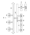
- FIG. 1 is a block diagram illustrating a hardware configuration of, for example, a PC as an information processing apparatus including a mark information recording apparatus and a mark information presentation apparatus according to an embodiment of the present technology.
- FIG. 2 is a diagram showing an image pyramid structure for explaining a display principle of an image having a pyramid structure.
- FIG. 3 is a diagram for explaining a procedure for generating an image group having the image pyramid structure.
- FIG. 4 is a diagram illustrating an example of the sizes of the entire image and the output target image.
- FIG. 5 is a block diagram illustrating a system configuration of the information processing apparatus.
- FIG. 6 is a diagram showing a mark information management table managed by the mark information management unit.
- FIG. 1 is a block diagram illustrating a hardware configuration of, for example, a PC as an information processing apparatus including a mark information recording apparatus and a mark information presentation apparatus according to an embodiment of the present technology.
- FIG. 2 is a diagram showing an image pyramid structure for explaining a display principle of an image having
- FIG. 7 is a diagram illustrating an example of an output target image in which a mark image that is mark information associated with an arbitrary position in the entire image is combined.
- FIG. 8 is a flowchart illustrating processing by the information processing apparatus according to the first embodiment of the present technology.
- FIG. 9 shows an example of a candidate screen for a list of clipped images.
- FIG. 10 shows an example of a screen for allowing the user to specify the magnification, size, and the like.
- 11A to 11C are diagrams showing images having different depths.
- FIG. 12 is a flowchart illustrating a process performed by the information processing apparatus according to the second embodiment of the present technology.
- FIG. 13 shows an example of a screen according to the second embodiment.
- FIG. 14 is a flowchart illustrating a process performed by the information processing apparatus according to the third embodiment of the present technology.
- FIG. 15 shows an example of a screen according to the third embodiment.
- FIG. 16 shows a mark information management table used in Embodiment 4 of the present technology.
- FIG. 17 is a flowchart illustrating processing by the information processing apparatus according to the fifth embodiment of the present technology.
- FIG. 18 shows an example of a screen according to the fifth embodiment.
- FIG. 19 is a flowchart illustrating processing by the information processing apparatus according to the sixth embodiment of the present technology.
- FIG. 20 shows an example of a screen according to the sixth embodiment.
- FIG. 21 is a flowchart illustrating processing by the information processing apparatus according to the seventh embodiment of the present technology.
- FIG. 21 is a flowchart illustrating processing by the information processing apparatus according to the seventh embodiment of the present technology.
- FIG. 22 shows an example of a screen according to the seventh embodiment.
- FIG. 23 is a flowchart illustrating processing by the information processing apparatus according to the eighth embodiment of the present technology.
- FIG. 24 is a flowchart illustrating processing by the information processing apparatus according to the ninth embodiment of the present technology.
- FIG. 25 shows an example of a screen according to the ninth embodiment.
- FIG. 1 is a block diagram illustrating a hardware configuration of, for example, a PC (Personal Computer) as an information processing apparatus including a mark information recording apparatus and a mark information presentation apparatus according to an embodiment of the present technology.
- PC Personal Computer
- the PC 100 includes a CPU (Central Processing Unit) 101, a ROM 102 (Read Only Memory), a RAM (Random Access Memory) 103, an input / output interface 105, and a bus 104 that connects these components to each other.
- a CPU Central Processing Unit
- ROM Read Only Memory
- RAM Random Access Memory
- a display unit 106, an input unit 107, a storage unit 108, a communication unit 109, a drive unit 110, and the like are connected to the input / output interface 105.
- the display unit 106 is a display device using, for example, liquid crystal, EL (Electro-Luminescence), or the like.
- the input unit 107 is, for example, a pointing device, a keyboard, a touch panel, a microphone, and other operation devices.
- the input unit 107 includes a touch panel, the touch panel can be integrated with the display unit 106.
- the storage unit 108 is a non-volatile storage device, such as an HDD (Hard Disk Drive), flash memory, or other solid-state memory.
- HDD Hard Disk Drive
- flash memory or other solid-state memory.
- the drive unit 110 is a device capable of driving a removable recording medium 111 such as an optical recording medium, a magnetic recording tape, a flash memory, or the like.
- the storage unit 108 is often used as a device mounted in advance on the PC 100, which mainly drives a non-removable recording medium.
- the communication unit 109 is a modem, router, or other communication device that can be connected to a LAN (Local Area Network), a WAN (Wide Area Network), or the like to communicate with other devices.
- the communication unit 109 may communicate using either wired or wireless communication.
- the communication unit 109 may be used separately from the PC 100.
- FIG. 2 is a diagram showing an image pyramid structure for explaining the display principle.
- the image pyramid structure 50 in the present embodiment is an image group (entire image group) generated with a plurality of different resolutions for the same image obtained from the same one observation object 15 (see FIG. 3) with an optical microscope. is there.
- the largest image is arranged at the bottom of the image pyramid structure 50, and the smallest image is arranged at the top.
- the resolution of the largest image is, for example, 50 ⁇ 50 (Kpixel: kilopixel), or 30 ⁇ 40 (Kpixel) as shown in FIG.
- the smallest size image is, for example, 256 ⁇ 256 (pixel) or 256 ⁇ 512 (pixel).
- the display range of the display unit 106 is indicated as D.
- the image in the area indicated in the display range D is an image to be output to the display unit 106.
- FIG. 3 is a diagram for explaining a procedure for generating an image group of the image pyramid structure 50.
- a digital image of an original image obtained at a predetermined observation magnification by an optical microscope (not shown) is prepared.
- This original image corresponds to the image of the largest size that is the lowermost image of the image pyramid structure 50 shown in FIG. 2, that is, the image with the highest resolution. Therefore, as the lowermost image of the image pyramid structure 50, an image of an optical microscope obtained by observing at a relatively high magnification is used.
- an observation object 15 is obtained by thinly cutting a living organ, tissue, cell, or part thereof. Then, the observation object 15 stored on the glass slide is read by a scanner device (not shown) having the function of an optical microscope, and a digital image obtained thereby is stored in the scanner device or other storage device.
- the scanner device or a general-purpose computer (not shown) generates a plurality of images having resolutions reduced step by step from the image having the largest size obtained as described above. Is stored in units of “tiles”. The size of one tile is, for example, 256 ⁇ 256 (pixel).
- the image group generated in this way forms an image pyramid structure 50, and this image pyramid structure 50 is stored in the storage unit 108 of the PC 100. Actually, the PC 100 only needs to store the images having the plurality of different resolutions and the resolution information in association with each other.
- the generation and storage of the image pyramid structure 50 may be executed by the PC 100 shown in FIG.
- the entire image other than the original image having the largest size may be generated by a known compression method based on the original image, for example, a thumbnail image is generated. It may be generated by a known compression method.
- the PC 100 uses software that employs the system of the image pyramid structure 50 to extract a desired image from the image pyramid structure 50 in accordance with information on an input operation through the user input unit 107, and displays it on the display unit 106. Output to. Specifically, the PC 100 displays an image of an arbitrary part designated by the user among images having an arbitrary resolution selected by the user.
- an image 210 that is a part of the entire image 200 having any one resolution among the entire images having a plurality of different resolutions is designated by the user's input operation.
- the PC 100 has the entire images 200 having a plurality of different resolutions.
- the image 210 is designated by the user's input operation, the PC 100 can output the image of the designated area to the display unit 106 as the output target image 210.
- FIG. 4 shows an example in which the output target image 210 is generated from the largest original image.
- the display unit 106 displays the generated output target image 210 as an entire screen of the display unit 106 by HD (High Definition), for example.
- the display unit 106 can also display the output target image on a part of the screen.
- the display unit 106 can display an output target image 210 having an arbitrary resolution, and the resolution of the output target image 210 depends on the resolution of the entire image that is the original image.
- the user can obtain a feeling of observing the observation object 15 while changing the observation magnification. That is, the PC 100 functions as a virtual microscope.
- the virtual observation magnification here actually corresponds to the resolution.
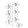
- FIG. 5 is a block diagram showing a system configuration of the information processing apparatus.
- This system includes a display control unit 51, a user operation information acquisition unit 52, a cut-out image generation unit 53, a user information management unit 54, a mark information management unit 55, a huge image management unit 56, and a storage unit 108.
- the display control unit 51 generates an output target image and an image for displaying other screens, and functions as an output unit.
- the hardware responsible for the display control unit 51 is mainly at least one of the CPU 101 and the input / output interface 105.
- the user operation information acquisition unit 52 is mainly operated by the user via the input unit 107 so that the user can browse the output target image or extract a clipped image from the output target image as will be described later. It functions as an acquisition unit.
- the hardware responsible for the user operation information acquisition unit 52 is mainly at least one of the CPU 101, the input / output interface 105, and the input unit 107.
- the cutout image generation unit 53 mainly has a function of generating the cutout image according to a predetermined condition described later, and functions as a generation unit.
- the hardware responsible for the cut-out image generation unit 53 is mainly the CPU 101.
- the user information management unit 54 manages the ID for each user.
- the user information management unit 54 may manage a password associated with an ID for each user.
- the hardware responsible for the user information management unit 54 is mainly the CPU 101 and the storage unit 108.
- the mark information management unit 55 mainly manages mark information, which is additional information for the entire image of the user, and uses the mark information as position information (coordinate information) in the entire image and its resolution (magnification) as described later. ) To store the information in association with the information. In addition, the mark information management unit 55 cooperates with the cutout image generation unit 53 to provide the cutout image generation unit 53 with information necessary for generating the cutout image.
- the hardware responsible for the mark information management unit 55 is mainly the CPU 101 and the storage unit 108.
- the mark information is at least one of a symbol, a code, an index, annotation information, and an image representing these.
- an image expressing a symbol, code, index, and annotation information is referred to as a mark image.
- Annotation information is information formed by text, sound, images, links (for example, URL: Uniform Resource Locator), etc., and may be associated with the above symbols, codes, indexes, and the like.
- the huge image management unit 56 mainly stores the entire image group, reads an entire image having an arbitrary resolution from the entire image from the storage unit 108, and performs other processes related to the management of the entire image. Or run.
- the hardware responsible for the huge image management unit 56 is mainly the CPU 101 and the storage unit 108.
- FIG. 6 is a diagram showing a mark information management table managed by the mark information management unit 55.
- the mark information includes a mark image and annotation information.
- the annotation information includes text information and audio information.
- the mark information is associated with arbitrary position information in the entire image of any one resolution, that is, coordinate information and magnification, and these are stored as recording coordinate information (recording position information) and recording magnification information (recording resolution information). Stored in the unit 108.
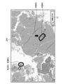
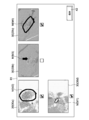
- FIG. 7 is a diagram illustrating an example of an output target image in which mark images M (M1 to M4) that are mark information associated with arbitrary positions in the entire image are combined.
- mark images M M1 to M4
- four mark images M are combined in this one output target image 210.
- the mark image M is composed of a circular encircling line (for example, a colored line) and a colored arrow.
- the mark image is used by the user to add that there is an abnormal cell in the circular line or at the position indicated by the arrow.
- the mark image M may be of any type.
- the mark image M is formed by a surrounding line, an arrow, a point, a circle, a polygon, or a combination thereof as shown in FIG. 7, and these mark images M can be selected by the user.
- the color of the mark image M can also be selected by the user.
- the user adds a circular line in the mark image M by handwriting input or the like while viewing the output target image using application software included in the information processing apparatus.
- the arrow may be added automatically by the application software, or may be added manually by the user.
- the mark information management unit 55 stores the mark image M, the coordinate information of the portion where the mark image M is combined, and the text information in association with each other, and creates the management table shown in FIG.
- the coordinate information of the place where the mark image M is synthesized is, for example, the coordinates of the center of gravity of the outer shape of the circular line, but may be anywhere on the screen, such as the uppermost part or the leftmost part of the mark image M.
- the coordinates recorded in the management table are set at the position of the tip of the arrow or a position separated from the tip by a predetermined distance.
- the coordinates recorded in the management table may be anywhere such as the center coordinates of the output target image 210 output when the mark information is recorded, or the uppermost and leftmost coordinates.
- the size of the mark image M itself is displayed in a predetermined size regardless of the resolution of the entire image.
- the size of the mark information may be set to a predetermined value in advance, or may be customizable by the user.
- the information processing apparatus can be configured such that the user moves a pointer displayed on a screen moved by a mouse to the recorded coordinate position or the vicinity thereof, or clicks the coordinate position or the vicinity thereof. Displays the text information on the screen.
- the annotation information is audio information
- the information processing apparatus reproduces the audio information in accordance with the predetermined operation as described above by the user.
- the annotation information recorded in the management table shown in FIG. 6 may be a URL indicating the location of a file constituting the annotation information.
- the information representing the mark information (presence) is visualized as the mark image M, so that the user can access the mark information based on the mark image M image while browsing the output target image. it can.
- the processing of the PC 100 described below is realized by cooperation between stored software such as the storage unit 108 or the ROM 102 and hardware resources of the PC 100. Specifically, the following processing is realized by the CPU 101 loading a program constituting the software stored in the storage unit 108 or the ROM 102 into the RAM 103 and executing the program. For convenience of explanation, the processing will be described assuming that the processing subject is the CPU 101.
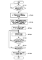
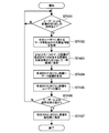
- FIG. 8 is a flowchart illustrating processing by the information processing apparatus according to the first embodiment of the present technology.
- the CPU 101 outputs the output target image 210 as shown in FIG. Specifically, when the output coordinate group (output position group) constituting the output target image 210 includes recording coordinates related to the mark information added by the user, the CPU 101 The output target image 210 is output by combining M. When the output target image 210 includes a plurality of mark information added by the user, the plurality of mark images M are synthesized and output (see FIG. 7).
- the user information management unit 54 can identify the user.
- the user information management unit 54 may identify a user by a process for logging the user in with an ID and a password when the information processing apparatus (application software according to the present technology) is activated or is being used. it can.
- a GUI (Graphical User Interface) button for “image cutout” is provided at the lower right of the screen including the output target image 210.
- the CPU 101 acquires information on the input operation for specifying the cut-out, and the mark information about the user and the related information Is acquired (step 102).
- the related information is information of at least recording coordinates and recording magnification associated with the mark information.
- the CPU 101 cuts out an image having a size in which the mark image M can be accommodated at the observation magnification at the time of recording the mark information (hereinafter simply referred to as magnification) from the entire image, and stores them in a temporary storage area provided in the RAM. Save (step 103). Further, the CPU 101 synthesizes a mark image M corresponding to the recording coordinates with the cutout images (step 104). Then, as shown in FIG. 9, the CPU 101 generates a candidate screen 61 for allowing the user to select a target for saving the clipped image 30 (30a to 30d) in the storage unit 108, and outputs this (step 105). ). At this time, the CPU 101 functions as a candidate screen generation unit.
- the magnifications of the generated cutout images 30 are the magnifications of the whole image output at the time of recording the mark information, that is, the recording magnifications recorded in the management table. Therefore, the sizes of these cut-out images 30 are different (of course, they may be the same). However, on the candidate screen 61 shown in FIG. 9, the CPU 101 displays these images as if they are the same size, that is, displays the cut-out images 30 as thumbnail images.
- the cut-out images 30 may be formed so that the center of gravity of the mark image M is located at the center coordinates of the cut-out image 30. That is, the center coordinates of the cut-out image 30 become recording coordinates associated with the mark information.
- the cutout image 30 may be formed on the basis of coordinates other than the center of gravity of the mark image M.
- the size in which the mark image M can be accommodated is such that the vertical or horizontal size of the cutout image 30 is, for example, about 1.2 to 2 times the vertical or horizontal size of the outer shape of the mark image M. .
- the vertical or horizontal size of the cutout image 30 may be the same as the vertical or horizontal size of the outer shape of the mark image M.
- the CPU 101 waits for an instruction from the user to change the magnification, depth, and size of the cut-out images 30 (step 106). For example, as shown in the upper left diagram of FIG. 10, the user can change the cut-out image 30 through the adjustment units 45, 46, and 47 using the magnification, depth, and size GUIs synthesized at predetermined positions. Can be set. The “depth” will be described later.
- magnifications of 5 times and 20 times are selected by the check box 43 by the user.
- candidates for the cutout image 30 having the same coordinates (for example, center coordinates) as the recording coordinates of the cutout image 30 in the upper left in the entire image having the magnification of 5 and 20 times are arranged.
- a screen is generated.
- 11A to 11C are diagrams showing images having different depths.
- the images having different depths are images having different focus of the objective lens of the microscope, and these images are whole images having the same magnification and different in focus.
- the target object of the original image observed with an actual microscope is contained in a preparation, but has a predetermined thin thickness.
- a plurality of whole images formed by changing the focus in a predetermined plurality of stages by the thickness are stacked in the thickness direction.
- this technique is called a Z stack.
- the total number of images stacked by the Z stack is, for example, 5 to 20, but is not limited to this range.
- the storage unit 108 may store images of a plurality of Z stacks for each entire image having the same magnification.
- the user observes the object (image) using this information processing apparatus as if it is focused on a predetermined depth position of the actual object having a predetermined thickness. be able to. That is, the present technology is useful when different cells exist at different depth positions.
- the user can designate an entire image corresponding to one depth position among the entire images stored at a plurality of depth positions via the adjustment unit 46.
- a partial image of the output target image 210 including the coordinate information associated with the mark information in the entire image is cut out and the cut-out image 30 is generated. Therefore, the user can see the cutout image 30 associated with the mark information, which is convenient.
- the cutout image 30 is generated according to at least one of the magnification, depth, and size specified by the user, and an image that is easy for the user to view can be generated.
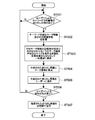
- FIG. 12 is a flowchart illustrating a process performed by the information processing apparatus according to the second embodiment of the present technology.
- the description of the same process as the process according to the first embodiment will be simplified or omitted, and different points will be mainly described.
- the process according to the second embodiment is a process in a case where a plurality of recording coordinates respectively associated with a plurality of pieces of mark information are included in the output coordinate group constituting the output target image 210 to be output. Also in the first embodiment, the output coordinate group constituting the output target image 210 includes a plurality of recording coordinates. However, the processing according to the first embodiment is performed for each mark information (recording position). A cut-out image was generated for each recording magnification.
- the CPU 101 determines whether or not the output coordinate group constituting the current output target image 210 includes a plurality of recording coordinates respectively associated with a plurality of mark information (step 203).
- step 203 the CPU 101 determines whether at least one of the plurality of recording magnifications corresponding to the plurality of recording coordinates is equal to or exceeds the current output magnification of the output target image 210. It is determined whether or not (step 204). In the example shown in FIG. 13, when the recording magnification corresponding to the mark image M5 among the recording magnifications corresponding to the two mark images M5 and M6 matches or exceeds the current output magnification of the output target image 210. To do.
- step 204 the CPU 101 generates an image of the area 32 including the recording coordinates corresponding to at least one recording magnification as the cutout image 30 (step 205). That is, the cutout region 32 is cut out from the output target image for each of a plurality of recording coordinates.
- a cutout image 30 corresponding to the mark image M5 that matches the current magnification of the output target image 210 is generated.
- a mark image M6 represented by an arrow having a recording magnification smaller than the magnification of the current output target image 210 is ignored.
- the CPU 101 executes the same processing as steps 104, 105, 107 and 108 in that order.
- the user can obtain the cutout image 30 having a recording magnification corresponding to the resolution of the current output target image 210.
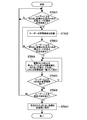
- FIG. 14 is a flowchart illustrating a process performed by the information processing apparatus according to the third embodiment of the present technology.
- the CPU 101 determines whether or not a plurality of mark images M (M7 and M8) can be accommodated in one cutout area 32 as shown in the upper diagram of FIG. 15 (step 303). Specifically, the CPU 101 includes a plurality of recording coordinates (here, the recording magnification corresponding to each of the mark images M is within the same or a predetermined difference range and has a set cut size). Then, it is determined whether or not a plurality of mark images M) can be accommodated.
- a default value may be set as appropriate, for example, 5, 10, 15, or the like, and it may be customizable by the user.
- the set cut-out size may be a default size, or it may be customizable by the user.
- step 303 the CPU 101 makes an inquiry for allowing the user to select either one of the cutout images 30 or the cutout image 30 for each mark image M (see FIG. For example, an inquiry screen (not shown) is presented) (step 304).
- the CPU 101 determines the recording coordinates and the recording magnification associated with each mark image M according to the recording coordinates and the recording magnification. For each image in the region including the recording coordinates, a cutout image 30 having these magnifications is generated (step 306). Here, an example of a screen related to this processing is not shown. Thereafter, the CPU 101 executes processing similar to that in steps 104, 105, 107 and 108 shown in FIG. 8 in that order (steps 307 to 310).
- step 306 at least two of the recording magnifications may be the same or within a predetermined difference range. However, this case is a case where a plurality of recording coordinates cannot be contained within one cut-out size.
- the CPU 101 generates one image of the region 32 having the recording magnification and including those recording coordinates as the cutout image 30 (step 311).
- the CPU 101 calculates the average value, the median value, the lowest value, or the value closest to them. Then, one image of the region 32 having the recording magnification obtained by the calculation and including those recording coordinates may be generated as the cutout image 30.
- the user may be allowed to select an algorithm for calculating the magnification of these cut-out images 30.
- the cutout image 30 may be generated so that the barycentric positions of a plurality of recording coordinates correspond to the center position of the cutout image 30. Thereby, the cut-out image 30 including the recording coordinates of the plurality of mark images M arranged with good balance can be generated.
- the cutout image 30 may be formed such that a position other than the center of gravity corresponds to a predetermined position in the cutout image 30.
- the CPU 101 synthesizes the mark images M (M 7 and M 8) with the generated cutout image 30 and identifies them in the mark image M as shown in the lower diagram of FIG.
- the images (for example, numbers) L (L1 and L2) to be used are synthesized (step 312). There may be a setting in which the identification image L of the mark image M is not given. Thereafter, the CPU 101 executes the processing of steps 308 to 310.
- the identification image L of the mark image M is assigned in order from the upper left to the lower right as in the raster scan, or the recording order of the mark information by the user (time stamp). and so on. In order to realize the latter form, it is necessary to record the time stamp of the mark information in the mark information management table.
- step 303 it may be determined whether or not a plurality of mark images M fit within the area 32 having the set cut-out size without using the recording magnification as a target of the determination process.
- step 311 their recording magnifications vary. Therefore, in this case, instead of the step 311, the CPU 101 may calculate, for example, the minimum value of the recording magnifications and generate one cutout image 30 having the minimum recording magnification.
- FIG. 16 shows a mark information management table used in Embodiment 4 of the present technology.
- a magnification range (recording magnification range (recording resolution range)) configured with at least two or more magnifications including the X value. Is set.
- the CPU 101 determines whether or not the output magnification of the current output target image 210 is within the recording magnification range described above, for example, instead of step 204 shown in FIG. do it. If the determination process is Yes, the CPU 101 may proceed to step 205.
- FIG. 17 is a flowchart illustrating processing by the information processing apparatus according to the fifth embodiment of the present technology.
- the CPU 101 When the output coordinate group constituting the output target image 210 includes recording coordinates of a plurality of mark information (mark images M9 and M10), the CPU 101 at least one of the mark images M. An image of the region 32 having a size that can accommodate M is generated as the cutout image 30 (step 403).
- the user can select an algorithm for calculating the magnification of these cutout images 30. According to this embodiment, the user can arbitrarily specify the region 32 for cutout and generate the cutout image 30.
- the magnification of the cut-out image 30 may be the output magnification of the output target image 210 currently output, or the CPU 101 may select the optimum magnification to generate the cut-out image 30.
- the optimum magnification may be an average value, an intermediate value, a minimum value, or the closest value to the magnification corresponding to each of the plurality of pieces of mark information.
- FIG. 19 is a flowchart illustrating processing by the information processing apparatus according to the sixth embodiment of the present technology. This embodiment is applied when text information is included in mark information.
- the CPU 101 determines whether there is an instruction to cut out an image based on a keyword (designated keyword) input by the user (step 501).
- FIG. 20 shows an example of a screen including an input box 48 in which a keyword is input by the user. If the result of step 501 is Yes, the CPU 101 acquires mark information including the keyword and related information (step 502). In the example shown in FIG. 20, mark information (mark image M) including “check”, “level 3”, and the like as keywords is displayed.
- the CPU 101 generates, as the cutout image 30, an image having a size that can accommodate the mark image M including at least one recording coordinate at the magnification at the time of recording the mark information including the keyword (step 503).
- the cut-out image 30 is generated for each piece of the mark information.
- the user can select desired mark information from a plurality of mark information by keywords.
- FIG. 21 is a flowchart illustrating processing by the information processing apparatus according to the seventh embodiment of the present technology.
- the cut-out image generation unit 53 has a whole image browsing mode (image cut-out browsing mode) for generating a cut-out image. In this mode, when the user pans and browses the entire image, a cut-out image is automatically generated based on operation state information input via the input unit 107 by the user.
- FIG. 22 shows a locus of an output target image 210 (shown by a rectangular broken line) in the entire image 200 that is output by a series of continuous or intermittent designation operations by the user.
- the output target image group on the locus is composed of a plurality of images in which at least one of the output coordinates and the output magnification is different from each other.
- FIG. 22 the image shown in FIG. 22 is represented as all of the entire image 200, and FIG. 22 is output as a screen by the display control unit 51 in the entire image 200.
- the locus of the output target image 210 is expressed.
- a mode start button 49 (or a stop button displayed by a toggle operation may be provided) is provided at the lower right of the screen. However, the start button 49 (and the stop button) may not be necessarily provided. .
- the CPU 101 stores the user's browsing trajectory in, for example, a temporary area (Step 602). Specifically, the CPU 101 stores the coordinates of the output target image 210 with a time stamp (generation date / time) added thereto.
- the coordinates of the output target image 210 may be representative coordinates at a predetermined position in the output target image 210, and are, for example, center coordinates, uppermost left coordinates, and the like.
- the CPU 101 stores N seconds (3 seconds in the example of FIG. 22) in the output target image 210 in the browsing locus stored in the temporary area. ) As described above, the output target image 210 output while staying at the same position is generated as a cut-out image based on the information of the representative coordinates corresponding thereto. Whether or not the output target image 210 is an image output for N seconds or more can be determined by a time stamp.
- the output target images 210 are presented to the user as an image candidate list (candidate screen) (step 604).
- the operation state of the user means an operation for keeping the output target image 210 at the same position for N seconds or longer. The operation is such that the user does not move the mouse or the like at the same position.
- Step 605 When there is a request for changing the N value by an input operation by the user (Yes in Step 605), the CPU 101 returns to Step 604.
- the CPU 101 generates the output target image 210 output for N seconds or longer as a cutout image.
- a part of the output target image 210 output for N seconds or longer may be generated as a cutout image.
- the size of the cutout image 30 may be changed according to the number of seconds for each output target image 210 output for N seconds or more.
- the CPU 101 can increase (or decrease) the size of the cutout image 30 as the number of seconds is longer.
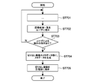
- FIG. 23 is a flowchart illustrating processing by the information processing apparatus according to the eighth embodiment of the present technology.
- the CPU 101 executes generation of the cutout image 30 in any one of the first to seventh embodiments, presents the image candidate list to the user in the same manner as described above, and saves the cutout image 30 by the user. Wait for instructions (steps 701 to 703).
- the CPU 101 embeds (generates) metadata in the metadata part of the cutout image 30 (step 704).
- the CPU 101 functions as a metadata generation unit.
- the cutout image 30 is generated as a file such as JPEG (Joint Photographic Experts Group), TIFF (Tagged Image File Format), GIF (Graphic Interchange Format), or PNG (Portable Network Graphics).
- the metadata includes the coordinates and magnification of the generated cutout image 30, and also includes information such as depth or image size.
- the metadata includes information on the system of the information processing device, information on the ID (or URL) of application software for browsing the entire image, or the original entire image from which the cut-out image 30 is cut out. It is information such as URL that indicates where you are.
- the CPU 101 stores the cutout image 30 including the metadata in the storage unit 108 (step 705).
- the application software ID or its URL is generated as metadata, and for example, the user right-clicks the cut-out image 30 and selects “Start Viewer”.
- CPU101 can start the application software.
- the CPU 101 can output at least a part of the entire image 60 centered on the image including the coordinate area of the cut-out image 30 for display.
- the CPU 101 can also execute the output of the cut-out image 30 according to the magnification, depth, size, etc. included in the metadata.
- the information processing apparatus and another information processing apparatus are connected via a LAN or the Internet, the following processing is also possible.
- the other information processing apparatus that does not have the application software of the information processing apparatus displays the cut-out image 30 and “starts Viewer”, the other information processing apparatus virtually copies the application of the information processing apparatus. You can use it or install this application.
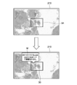
- FIG. 24 is a flowchart illustrating processing by the information processing apparatus according to the ninth embodiment of the present technology.
- the CPU 101 generates at least one cutout image 30 from the entire image based on, for example, information of an input operation by the user (step 801). Steps 802 to 804 are similar to steps 105 and 107 to 108.
- the information on the input operation by the user is information on the input operation when the user designates at least a part of the region 34 in the output target image 210 using a mouse or the like as shown in FIG. 25, for example. .
- the CPU 101 generates mark information on the basis of information such as coordinates and magnification, which are related information of the generated cutout image 30 (step 805).
- This magnification is the output magnification of the output target image 210 output at the time of clipping.
- the mark information includes, for example, a magnification, a time stamp at the time of clipping, user information, and the like. In the example illustrated in FIG. 25, these pieces of information are combined as a mark image M with the output target image 210 (entire image). .
- Step 806 When the mark information is corrected by the user's input operation (Yes in Step 806), the CPU 101 reflects the correction (Step 807), and stores the clipped image 30 and the corresponding mark information in the storage unit 108. (Step 808).
- the cut-out image 30 thus obtained and the mark information corresponding thereto are managed by the mark information management unit 55 described above.
- mark information is recorded in association with the cutout image 30 generated by the user's input operation. Therefore, a function for browsing the cutout image 30 using the mark information (mark image M) as an index, a search function for the cutout image 30 based on the mark information, and the like, that is, the cutout image 30 is used (cutout). A convenient function (for viewing the image 30) can be realized.
- the processing according to the eighth embodiment may also be applied to the cutout image 30 generated in the sixth embodiment. [Other embodiments]
- the CPU 101 when the CPU 101 acquires information of an input operation such as a user pressing the GUI image cutout button 41, the CPU 101 reads out the cutout image according to various conditions according to the above embodiments. 30 was produced. However, the CPU 101 may generate the cut-out image 30 according to various conditions according to the above-described embodiments even when the user's input operation information is not acquired.
- the processing performed by the cutout image generation unit 53 includes processing that does not include the processing through the candidate screen 61 for the cutout target image as illustrated in the above embodiments.
- the process without the process is a process of generating the cutout image 30 in accordance with various conditions according to each of the above embodiments, triggered by the output target image 210 being displayed.
- mark information instead of the mark image M or in addition to the mark image M, audio information may be recorded in association with recording coordinates and recording magnification information.
- the mark image M may not be present.
- a visually handicapped person or the like can also use the information processing apparatus according to the present technology.
- an image obtained by a microscope such as a cell or tissue
- a microscope such as a cell or tissue
- the present technology can be applied to any object such as a substance (liquid or crystal), a machine part, a map, and the like.
- the present technology can be configured as follows. (1) The position information in the entire image of any one resolution among the entire images respectively generated at a plurality of different resolutions for one object, and information on at least the one resolution of the entire image A storage unit that associates mark information that is additional information, and stores the position information and the resolution information associated with the mark information as recording position and recording resolution information, respectively. An output unit that outputs at least a part of the entire image of any one resolution for display as an output target image; An information processing apparatus comprising: a generation unit that generates a cutout image by cutting out an image of an area including the recording position associated with the mark information in the output target image from the output target image.
- the information processing apparatus according to (1), The information processing apparatus, wherein the generation unit generates the clipped image from the output target image having a resolution specified by the user.
- the information processing apparatus according to any one of (1) to (3), When a plurality of recording positions each associated with a plurality of mark information are included in the output position group constituting the output target image to be output, the generation unit is configured to store information on the plurality of recording positions. An information processing apparatus that extracts an image from the output target image for each of the plurality of recording positions.
- the information processing apparatus cuts out an image of an area including information on the plurality of recording positions from the output target image for each of a plurality of recording resolutions corresponding to the plurality of recording positions, respectively (6) (1) to (3)
- An information processing apparatus according to any one of the above, A plurality of recording resolutions respectively corresponding to the plurality of recording positions, wherein a plurality of recording positions each associated with a plurality of mark information are included in the output position group constituting the output target image to be output
- the generation unit includes a recording position corresponding to the at least one recording resolution.
- the output position group constituting the output target image to be output includes a plurality of recording positions each associated with a plurality of mark information, and the plurality of recording positions are set in an image having a set cut-out size.
- the generation unit When the recording position falls within the range, the generation unit generates an image of an area including the plurality of recording positions as the one cut-out image.
- the generation unit uses an image of an area including the plurality of recording positions as the one cut-out image. Generate information processing device.
- the information processing apparatus (9) The information processing apparatus according to (7) or (8), The information processing apparatus generates the clipped image so that a center of gravity of the plurality of recording positions is a center of the clipped image. (10) The information processing apparatus according to any one of (1) to (3), The storage unit associates the mark information for each resolution range configured with at least two resolutions including the output resolution that is the resolution of the output target image output by the output unit, and the mark information is associated with each other. An information processing apparatus that stores the resolution range information that has been recorded as recording resolution range information.
- the information processing apparatus When the output position group constituting the output target image to be output includes a plurality of recording positions each associated with a plurality of mark information, the generation unit is an image of an area designated by the user. An information processing device that generates an image of an area including at least one recording position associated with at least one of the plurality of mark information as the cutout image. (12) The information processing apparatus according to any one of (1) to (3), When a plurality of recording positions each associated with a plurality of mark information are included in the output position group constituting the output target image to be output, the generation unit is configured by the user among the plurality of recording positions.
- An information processing apparatus that generates, as the cut-out image, an image of an area including one or more recording positions corresponding to a keyword included in the mark information including a specified keyword. (13) The information processing apparatus according to any one of (1) to (12), An information processing apparatus further comprising a metadata generation unit that generates metadata for information of the cut-out image generated by the generation unit. (14) The information processing apparatus according to any one of (1) to (13), The output unit outputs the output target image in which a mark image is synthesized as part or all of the mark information. (15) The information processing apparatus according to (14), The generation unit generates the cut-out image by cutting out an image of an area having a size that fits the mark image from the entire image, The output unit combines the mark image with the generated cutout image.
- the information processing apparatus according to any one of (1) to (15), An acquisition unit for acquiring information of an input operation by a user for the generation unit to start generating the cut-out image; A candidate screen generation unit that generates a candidate screen for allowing a user to select a target for saving a clipped image when the information of the input operation is acquired by the acquisition unit and generation of the clipped image is started by the generation unit; An information processing apparatus further comprising: (17) Out of the whole images respectively generated at a plurality of different resolutions for one object, at least a part of the whole image having an arbitrary resolution is output for display as an output target image.
- An output section An acquisition unit for acquiring information on an operation state by the user, including at least position information in the whole image designated by a user for causing the output unit to output the output target image; Of the plurality of output target images, at least one of the position information and the resolution information is output from the output unit in response to the user's continuous or intermittent series of the designation operations, the acquisition An information processing apparatus comprising: a generation unit that generates a cutout image by cutting out at least a partial region of the one or more output target images from the entire image based on the operation state information acquired by the unit. (18) Out of the whole images respectively generated at a plurality of different resolutions for one object, at least a part of the whole image having any one resolution is output for display as an output object image.
- An output section In accordance with a user input operation, a generation unit that generates a cutout image by cutting out at least a part of the output target image output from the output unit from the entire image;
- An information processing apparatus comprising: a recording unit configured to record mark information in association with position information and resolution information of the cutout image generated by the generation unit in the entire image.
- this technique can also take the following structures. (21) Out of the whole images respectively generated at a plurality of different resolutions for one object, at least a part of the whole image having an arbitrary resolution is output for display as an output object image. , In response to a user input operation, a cutout image is generated by cutting out at least a part of the output target image from the whole image, An information processing method for recording mark information in association with position information and resolution information of the generated cutout image in the whole image.
- the present technology can be configured as a program for a computer to execute each step of each of the above information processing methods.
Landscapes
- Engineering & Computer Science (AREA)
- Theoretical Computer Science (AREA)
- Physics & Mathematics (AREA)
- General Physics & Mathematics (AREA)
- Multimedia (AREA)
- Signal Processing (AREA)
- General Engineering & Computer Science (AREA)
- Human Computer Interaction (AREA)
- Editing Of Facsimile Originals (AREA)
- User Interface Of Digital Computer (AREA)
- Processing Or Creating Images (AREA)
Priority Applications (5)
| Application Number | Priority Date | Filing Date | Title |
|---|---|---|---|
| BR112014002853A BR112014002853A2 (pt) | 2011-08-12 | 2012-07-11 | aparelho e método de processamento de informação |
| EP12823564.5A EP2743890A4 (en) | 2011-08-12 | 2012-07-11 | Information processing device and information processing method |
| US14/237,275 US20140168256A1 (en) | 2011-08-12 | 2012-07-11 | Information processing apparatus and information processing method |
| CN201280037864.XA CN103718146A (zh) | 2011-08-12 | 2012-07-11 | 信息处理装置和信息处理方法 |
| CA2839870A CA2839870A1 (en) | 2011-08-12 | 2012-07-11 | Information processing apparatus and information processing method |
Applications Claiming Priority (2)
| Application Number | Priority Date | Filing Date | Title |
|---|---|---|---|
| JP2011-176601 | 2011-08-12 | ||
| JP2011176601A JP5906605B2 (ja) | 2011-08-12 | 2011-08-12 | 情報処理装置 |
Publications (1)
| Publication Number | Publication Date |
|---|---|
| WO2013024563A1 true WO2013024563A1 (ja) | 2013-02-21 |
Family
ID=47714902
Family Applications (1)
| Application Number | Title | Priority Date | Filing Date |
|---|---|---|---|
| PCT/JP2012/004479 Ceased WO2013024563A1 (ja) | 2011-08-12 | 2012-07-11 | 情報処理装置及び情報処理方法 |
Country Status (7)
| Country | Link |
|---|---|
| US (1) | US20140168256A1 (https=) |
| EP (1) | EP2743890A4 (https=) |
| JP (1) | JP5906605B2 (https=) |
| CN (1) | CN103718146A (https=) |
| BR (1) | BR112014002853A2 (https=) |
| CA (1) | CA2839870A1 (https=) |
| WO (1) | WO2013024563A1 (https=) |
Families Citing this family (5)
| Publication number | Priority date | Publication date | Assignee | Title |
|---|---|---|---|---|
| US9721186B2 (en) * | 2015-03-05 | 2017-08-01 | Nant Holdings Ip, Llc | Global signatures for large-scale image recognition |
| JP6631180B2 (ja) * | 2015-11-12 | 2020-01-15 | 株式会社リコー | 画像処理装置、画像形成装置、画像処理方法及びプログラム |
| CN105389383B (zh) * | 2015-11-30 | 2018-12-21 | 中国空间技术研究院 | 一种卫星总装影像记录查询方法 |
| CN111598133B (zh) * | 2020-04-22 | 2022-10-14 | 腾讯医疗健康(深圳)有限公司 | 基于人工智能的图像显示方法、装置、系统、设备及介质 |
| WO2021261323A1 (ja) * | 2020-06-24 | 2021-12-30 | ソニーグループ株式会社 | 情報処理装置、情報処理方法、プログラム及び情報処理システム |
Citations (5)
| Publication number | Priority date | Publication date | Assignee | Title |
|---|---|---|---|---|
| JP2003345236A (ja) * | 2002-05-22 | 2003-12-03 | Sony Corp | 地図描画装置、地図表示システム、地図描画方法、およびプログラム |
| JP2009245404A (ja) | 2008-04-01 | 2009-10-22 | Fujifilm Corp | 画像処理装置および方法並びにプログラム |
| JP2011091769A (ja) * | 2009-10-26 | 2011-05-06 | Sony Computer Entertainment Inc | 画像ファイル生成装置、画像処理装置、画像ファイル生成方法、画像処理方法、および画像ファイルのデータ構造 |
| JP2011118005A (ja) * | 2009-11-30 | 2011-06-16 | Sony Corp | 情報処理装置、情報処理方法及びそのプログラム |
| JP2011117991A (ja) * | 2009-11-30 | 2011-06-16 | Sony Corp | 情報処理装置、情報処理方法及びそのプログラム |
Family Cites Families (15)
| Publication number | Priority date | Publication date | Assignee | Title |
|---|---|---|---|---|
| US7738688B2 (en) * | 2000-05-03 | 2010-06-15 | Aperio Technologies, Inc. | System and method for viewing virtual slides |
| JP2002236640A (ja) * | 2001-02-08 | 2002-08-23 | Matsushita Electric Ind Co Ltd | 画像表示装置及び画像表示方法 |
| JP2003099357A (ja) * | 2001-09-20 | 2003-04-04 | Pfu Ltd | 画像生成処理装置、携帯端末、スライドショーシステム |
| JP5055120B2 (ja) * | 2004-09-01 | 2012-10-24 | アペリオ・テクノロジーズ・インコーポレイテッド | リニア・アレイを用いたマイクロスコープ・スライド・スキャナにおけるデータ管理システムおよび方法 |
| US20080129844A1 (en) * | 2006-10-27 | 2008-06-05 | Cusack Francis J | Apparatus for image capture with automatic and manual field of interest processing with a multi-resolution camera |
| US8254626B2 (en) * | 2006-12-22 | 2012-08-28 | Fujifilm Corporation | Output apparatus, output method and program for outputting a moving image including a synthesized image by superimposing images |
| US20090254867A1 (en) * | 2008-04-03 | 2009-10-08 | Microsoft Corporation | Zoom for annotatable margins |
| US20090307618A1 (en) * | 2008-06-05 | 2009-12-10 | Microsoft Corporation | Annotate at multiple levels |
| US8194102B2 (en) * | 2008-10-06 | 2012-06-05 | Microsoft Corporation | Rendering annotations for images |
| US8587617B2 (en) * | 2009-02-04 | 2013-11-19 | Raytheon Company | Apparatus and method for map zooming |
| US20100229115A1 (en) * | 2009-03-05 | 2010-09-09 | Microsoft Corporation | Zoomable user interface data generation |
| JP5589366B2 (ja) * | 2009-11-27 | 2014-09-17 | ソニー株式会社 | 情報処理装置、情報処理方法及びそのプログラム |
| JP5561027B2 (ja) * | 2009-11-30 | 2014-07-30 | ソニー株式会社 | 情報処理装置、情報処理方法及びそのプログラム |
| US8957920B2 (en) * | 2010-06-25 | 2015-02-17 | Microsoft Corporation | Alternative semantics for zoom operations in a zoomable scene |
| US10645344B2 (en) * | 2010-09-10 | 2020-05-05 | Avigilion Analytics Corporation | Video system with intelligent visual display |
-
2011
- 2011-08-12 JP JP2011176601A patent/JP5906605B2/ja not_active Expired - Fee Related
-
2012
- 2012-07-11 US US14/237,275 patent/US20140168256A1/en not_active Abandoned
- 2012-07-11 CA CA2839870A patent/CA2839870A1/en not_active Abandoned
- 2012-07-11 BR BR112014002853A patent/BR112014002853A2/pt not_active IP Right Cessation
- 2012-07-11 EP EP12823564.5A patent/EP2743890A4/en not_active Withdrawn
- 2012-07-11 CN CN201280037864.XA patent/CN103718146A/zh active Pending
- 2012-07-11 WO PCT/JP2012/004479 patent/WO2013024563A1/ja not_active Ceased
Patent Citations (5)
| Publication number | Priority date | Publication date | Assignee | Title |
|---|---|---|---|---|
| JP2003345236A (ja) * | 2002-05-22 | 2003-12-03 | Sony Corp | 地図描画装置、地図表示システム、地図描画方法、およびプログラム |
| JP2009245404A (ja) | 2008-04-01 | 2009-10-22 | Fujifilm Corp | 画像処理装置および方法並びにプログラム |
| JP2011091769A (ja) * | 2009-10-26 | 2011-05-06 | Sony Computer Entertainment Inc | 画像ファイル生成装置、画像処理装置、画像ファイル生成方法、画像処理方法、および画像ファイルのデータ構造 |
| JP2011118005A (ja) * | 2009-11-30 | 2011-06-16 | Sony Corp | 情報処理装置、情報処理方法及びそのプログラム |
| JP2011117991A (ja) * | 2009-11-30 | 2011-06-16 | Sony Corp | 情報処理装置、情報処理方法及びそのプログラム |
Non-Patent Citations (1)
| Title |
|---|
| See also references of EP2743890A4 |
Also Published As
| Publication number | Publication date |
|---|---|
| EP2743890A4 (en) | 2015-12-02 |
| CN103718146A (zh) | 2014-04-09 |
| US20140168256A1 (en) | 2014-06-19 |
| JP2013041357A (ja) | 2013-02-28 |
| BR112014002853A2 (pt) | 2017-03-01 |
| EP2743890A1 (en) | 2014-06-18 |
| CA2839870A1 (en) | 2013-02-21 |
| JP5906605B2 (ja) | 2016-04-20 |
Similar Documents
| Publication | Publication Date | Title |
|---|---|---|
| JP5617233B2 (ja) | 情報処理装置、情報処理方法及びそのプログラム | |
| JP5589366B2 (ja) | 情報処理装置、情報処理方法及びそのプログラム | |
| JP5561027B2 (ja) | 情報処理装置、情報処理方法及びそのプログラム | |
| JP6022732B2 (ja) | コンテンツ作成ツール | |
| KR20200121357A (ko) | 물리적 조작을 사용한 오브젝트 생성 | |
| US20110187741A1 (en) | Information processing apparatus and information processing program | |
| JP5853458B2 (ja) | マーク情報記録装置及びマーク情報提示装置 | |
| CN1853157A (zh) | 改善大物体在小显示器上的显示 | |
| JP5906605B2 (ja) | 情報処理装置 | |
| JP2009118060A (ja) | 画像表示装置、画像表示方法、および画像表示システム | |
| JP2013045069A (ja) | 情報処理システム及び情報処理方法 | |
| JP2010055424A (ja) | 画像を処理する装置、方法およびプログラム | |
| US8850359B2 (en) | Image processor and image processing method | |
| US8896627B2 (en) | Information display device, information display system, and computer program product | |
| JP2013171370A (ja) | 情報処理装置、情報処理方法、プログラム、及び情報処理システム | |
| CN104350456B (zh) | 信息处理装置和信息处理方法 | |
| JP2018173984A (ja) | 情報処理方法、情報処理システム、情報処理装置、プログラム、サーバ装置及び表示制御装置 | |
| JP2007041927A (ja) | 画像検索プログラム、画像検索装置、画像検索方法及び記録媒体 | |
| JP2005275979A (ja) | 画像検索プログラム | |
| JP6687946B2 (ja) | 画像処理方法及び画像処理プログラム | |
| JP2009176217A (ja) | 画像表示装置 | |
| JP2005063043A (ja) | 画像表示装置、画像表示方法および画像表示プログラム | |
| TWI566116B (zh) | 用於效能繪圖處理和突顯性導向學習至少其中一者的電子裝置 | |
| JP2006072523A (ja) | 画像表示装置及び画像表示方法 | |
| JP5308553B2 (ja) | コンテンツ作成装置及びカメラ |
Legal Events
| Date | Code | Title | Description |
|---|---|---|---|
| 121 | Ep: the epo has been informed by wipo that ep was designated in this application |
Ref document number: 12823564 Country of ref document: EP Kind code of ref document: A1 |
|
| ENP | Entry into the national phase |
Ref document number: 2839870 Country of ref document: CA |
|
| REEP | Request for entry into the european phase |
Ref document number: 2012823564 Country of ref document: EP |
|
| WWE | Wipo information: entry into national phase |
Ref document number: 14237275 Country of ref document: US |
|
| NENP | Non-entry into the national phase |
Ref country code: DE |
|
| REG | Reference to national code |
Ref country code: BR Ref legal event code: B01A Ref document number: 112014002853 Country of ref document: BR |
|
| ENP | Entry into the national phase |
Ref document number: 112014002853 Country of ref document: BR Kind code of ref document: A2 Effective date: 20140205 |