WO2013021973A1 - 受信装置、受信方法、及び受信プログラム - Google Patents
受信装置、受信方法、及び受信プログラム Download PDFInfo
- Publication number
- WO2013021973A1 WO2013021973A1 PCT/JP2012/070010 JP2012070010W WO2013021973A1 WO 2013021973 A1 WO2013021973 A1 WO 2013021973A1 JP 2012070010 W JP2012070010 W JP 2012070010W WO 2013021973 A1 WO2013021973 A1 WO 2013021973A1
- Authority
- WO
- WIPO (PCT)
- Prior art keywords
- transmission signal
- unit
- signal candidate
- candidate
- receiving apparatus
- Prior art date
- Legal status (The legal status is an assumption and is not a legal conclusion. Google has not performed a legal analysis and makes no representation as to the accuracy of the status listed.)
- Ceased
Links
Images








Classifications
-
- H—ELECTRICITY
- H04—ELECTRIC COMMUNICATION TECHNIQUE
- H04L—TRANSMISSION OF DIGITAL INFORMATION, e.g. TELEGRAPHIC COMMUNICATION
- H04L1/00—Arrangements for detecting or preventing errors in the information received
- H04L1/004—Arrangements for detecting or preventing errors in the information received by using forward error control
- H04L1/0045—Arrangements at the receiver end
- H04L1/0054—Maximum-likelihood or sequential decoding, e.g. Viterbi, Fano, ZJ algorithms
-
- H—ELECTRICITY
- H04—ELECTRIC COMMUNICATION TECHNIQUE
- H04B—TRANSMISSION
- H04B7/00—Radio transmission systems, i.e. using radiation field
- H04B7/02—Diversity systems; Multi-antenna system, i.e. transmission or reception using multiple antennas
- H04B7/04—Diversity systems; Multi-antenna system, i.e. transmission or reception using multiple antennas using two or more spaced independent antennas
- H04B7/0413—MIMO systems
-
- H—ELECTRICITY
- H04—ELECTRIC COMMUNICATION TECHNIQUE
- H04B—TRANSMISSION
- H04B7/00—Radio transmission systems, i.e. using radiation field
- H04B7/02—Diversity systems; Multi-antenna system, i.e. transmission or reception using multiple antennas
- H04B7/04—Diversity systems; Multi-antenna system, i.e. transmission or reception using multiple antennas using two or more spaced independent antennas
- H04B7/08—Diversity systems; Multi-antenna system, i.e. transmission or reception using multiple antennas using two or more spaced independent antennas at the receiving station
- H04B7/0837—Diversity systems; Multi-antenna system, i.e. transmission or reception using multiple antennas using two or more spaced independent antennas at the receiving station using pre-detection combining
- H04B7/0842—Weighted combining
- H04B7/0848—Joint weighting
- H04B7/0854—Joint weighting using error minimizing algorithms, e.g. minimum mean squared error [MMSE], "cross-correlation" or matrix inversion
Definitions
- the present invention relates to a receiving apparatus, a receiving method, and a receiving program that perform communication by MIMO transmission.
- MIMO Multiple Input Multiple Multiple Output
- MIMO transmission that uses a plurality of transmission / reception antennas and can perform high-speed transmission without widening the frequency bandwidth has been adopted in many systems.
- MIMO transmission since a plurality of data streams are transmitted using the same frequency, it is necessary to detect a MIMO signal in a receiving apparatus.
- MLD Maximum Likelihood Detection
- Non-Patent Document 1 describes a technique for reducing the amount of calculation of MLD by efficiently reducing transmission signal candidates.
- MLD is searched by searching for transmission signal candidates in the direction of noise enhancement, which is a cause of erroneous detection of MMSE (Minimum Mean Square Error), which is a linear detection with poor transmission characteristics but very small calculation amount.
- MMSE Minimum Mean Square Error
- Non-Patent Document 1 has a problem that the reception performance is significantly deteriorated when the spatial correlation of the MIMO channel is increased.
- the present invention has been made in view of such circumstances, and an object of the present invention is to provide a receiving apparatus, a receiving method, and a receiving program that can reduce performance degradation when the spatial correlation of a MIMO channel increases. It is.
- the present invention is a receiving apparatus that performs communication by MIMO transmission, and includes a transmission signal candidate search unit that searches for a transmission signal candidate in consideration of noise enhancement, and influence of spatial correlation of a channel on the searched signal.
- a transmission signal candidate generation unit that generates a transmission signal candidate by suppressing the transmission signal, and a determination unit that obtains a maximum likelihood sequence using the generated transmission signal candidate.
- the transmission signal candidate generation unit includes a first shift / scaling unit that performs shifting and scaling based on a modulation scheme, a basis conversion unit that performs basis conversion by multiplying a basis conversion matrix, and a quantization unit that rounds to an integer value
- a base inverse transform unit that performs an inverse operation of the basis transform unit, and a second shift / scaling unit that performs the reverse operation of the first shift / scaling unit to generate the transmission signal candidate. It is characterized by.
- the transmission signal candidate generation unit includes a base conversion unit that performs base conversion by multiplying a base conversion matrix, a first shift / scaling unit that performs shifting and scaling based on a modulation scheme, and a quantum that is rounded to an integer value.
- a second shift / scaling unit that performs the reverse operation of the first shift / scaling unit, and a base inverse transform unit that performs the reverse operation of the base transform unit to generate the transmission signal candidate. It is characterized by providing.
- These transmission signal candidate generation units generate the transmission signal candidates using the expanded channel matrix and the received signal.
- the transmission signal candidate search unit searches for transmission signal candidates in consideration of noise enhancement and an arbitrary position expressed by an IQ plane.
- the transmission signal candidate search unit searches for transmission signal candidates in consideration of noise enhancement and modulation schemes.
- the transmission signal candidate search unit searches for a corresponding transmission signal candidate for a part of signals in the linear detection result, and outputs the remaining signals after making a hard decision.
- the transmission signal candidate generation unit generates a transmission signal candidate using a channel corresponding to the partial signal.
- the present invention is further characterized by further comprising a candidate selection unit that selects whether or not to suppress the influence of the spatial correlation on the searched signal based on the spatial correlation of the channel.
- the candidate selection unit quantizes a signal that does not suppress the influence of spatial correlation to generate a transmission signal candidate, the determination unit transmits the transmission signal candidate generated by the transmission signal candidate generation unit, and the candidate selection unit A maximum likelihood sequence is obtained using the generated transmission signal candidates.
- the receiving apparatus further includes a decoding unit that performs error correction decoding, the determination unit obtains a bit log likelihood ratio of the maximum likelihood sequence, and the decoding unit includes a bit log likelihood of the maximum likelihood sequence. Error correction decoding is performed on the ratio.
- the determination unit obtains a bit log likelihood ratio of the maximum likelihood sequence from the transmission signal candidate and the decoded bit log likelihood ratio.
- the present invention also relates to a reception method in a reception apparatus that performs communication by MIMO transmission, a transmission signal candidate search process for searching for a transmission signal candidate in consideration of noise enhancement, and a channel for the searched signal.
- a transmission signal candidate generation process for generating a transmission signal candidate by suppressing the influence of the spatial correlation, and a determination process for obtaining a maximum likelihood sequence from the generated transmission signal candidate.
- the present invention is a reception program for causing a computer to execute each process of the reception method.
- the present invention generates a transmission signal candidate by performing processing for suppressing degradation due to spatial correlation of the MIMO channel after the signal search, so that even when the spatial correlation of the channel becomes high, the performance is improved. Deterioration can be suppressed.
- the number of transmission antennas is NT and the number of reception antennas is NR.
- the transmission data stream is transmitted from each transmission antenna, that is, the number of data streams is equal to the number of transmission antennas, but the present invention is not limited to this, and a plurality of data streams smaller than the number of transmission antennas Is also included in the present invention.
- FIG. 1 is a block diagram showing the configuration of the transmission apparatus of this embodiment.
- the transmission apparatus includes modulation sections 101-1 to 101-NT, a pilot signal generation section 102, a mapping section 103, and radio transmission sections 104-1 to 104-NT.
- the modulation units 101-1 to 101-NT map transmission bits to modulation symbols such as PSK (phase modulation: phase shift keying) and QAM (quadrature amplitude modulation: quadrature modulation).
- Pilot signal generation section 102 generates a pilot signal that is a known signal in the transmission / reception apparatus.
- Mapping section 103 arranges modulation symbols and pilot signals in resources.
- a resource is an area defined by frequency and time, but in the present embodiment, in order to show an application example in narrowband transmission, the resource in the present embodiment indicates time.
- the output of the mapping unit 103 is subjected to digital / analog conversion, waveform shaping, frequency conversion, etc. by the radio transmission units 104-1 to 104-NT, and transmitted from NT transmission antennas (not shown).
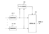
- FIG. 2 is a block diagram showing the configuration of the receiving apparatus in this embodiment.
- the reception apparatus includes radio reception units 201-1 to 201-NR, a channel estimation unit 202, and a signal detection unit 203.
- Received waves received by NR reception antennas are subjected to frequency conversion, filtering, analog / digital conversion by the radio reception units 201-1 to 201-NR, and output as reception signals.
- Channel estimation section 202 performs channel estimation using the pilot signal to obtain a channel estimation value.
- the signal detection unit 203 detects a transmission bit using the received signal and the channel estimation value.
- FIG. 3 is a schematic block diagram of the signal detection unit 203a.
- the signal detection unit 203a includes a transmission signal candidate search unit 301, a transmission signal candidate generation unit 302, and a determination unit 303.
- Transmission signal candidate search section 301 searches for a transmission signal in a direction in which reception performance deteriorates in MIMO signal detection. For example, in the case of ZF (Zero Forcing) detection and MMSE (Minimum Mean Square Error) detection, which are linear detection techniques, search for transmission signal candidates in the direction of noise enhancement.
- ZF Zero Forcing
- MMSE Minimum Mean Square Error
- the transmission signal candidate generation unit 302 generates a transmission signal candidate while suppressing deterioration due to channel spatial correlation. To do.
- the determination unit 303 obtains the maximum likelihood sequence using the transmission signal candidates generated by the transmission signal candidate generation unit 302. For the maximum likelihood sequence, a metric is calculated, and a transmission signal candidate that minimizes the metric is obtained. For example, when the received signal is expressed by Expression (1), the metric is obtained as Expression (2).
- y is an NR dimension received signal vector
- H is an NR row NT column channel matrix
- s is an NT dimension transmission signal vector
- n is an NR dimension noise vector
- H ⁇ is an NR row NT column channel estimation value
- s b is a bit sequence.
- b [b 1,1 ,..., b k, n ,..., b NT, N ]
- N log 2 M, where M is the number of constellations in the modulation scheme.
- MMSE detection uses the following weight matrix of NR rows and NT columns.
- superscript H represents a complex conjugate transpose matrix
- ⁇ n 2 represents average noise power
- INT represents a unit matrix of NT rows and NT columns.
- the matrix P is an Hermite matrix of NT rows and NT columns in which ⁇ n 2 P is an error covariance matrix.
- eigenvalue decomposition of P is performed as follows.
- V is a unitary matrix of NT rows and NT columns
- D is a diagonal matrix having eigenvalues ⁇ 1 to ⁇ NT as diagonal elements. It is assumed that the magnitude of the eigenvalue is ⁇ 1 ⁇ ⁇ 2 ⁇ . Since P is a positive definite matrix, all eigenvalues are positive, that is, ⁇ NT> 0. A large eigenvalue is considered to cause performance degradation. At this time, the signal s init after the search can be obtained as follows.
- x ⁇ is a signal after MMSE detection.
- Np is 1 ⁇ Np ⁇ NT, and represents the number of eigenvalues to be considered in the signal candidate search
- v k is the k-th column vector of the matrix V
- (A) k represents the k-th element of the vector A.
- B (m) represents one of the modulation symbols.
- M ⁇ NT + 1 signals can be obtained by adding x ⁇ .
- each element of a ⁇ (m, k) can be set as a random variable.
- the IQ plane is a plane having an I axis (in phase axis) on the horizontal axis and a Q axis (quadrature phase axis) on the vertical axis.
- the random variable can be set as a random variable according to a complex Gaussian distribution having a mean of zero and a variance ⁇ n 2 , for example.
- the number of s ⁇ init can be M ⁇ NT + 1 or more, or can be M ⁇ NT + 1 or less. If the number of s ⁇ init is reduced, the amount of calculation can be reduced, and if it is increased, reception performance such as bit error rate can be improved.
- the searched signal is quantized, a transmission signal candidate is obtained. However, if the spatial correlation of the channel is high, the probability that a correct transmission signal is included in the transmission signal candidate is low. Therefore, the transmission signal candidate generation unit 302 generates transmission signal candidates while suppressing the influence of channel spatial correlation.
- the transmission signal candidate generation unit 302 suppresses deterioration due to spatial correlation based on LR (Lattice Reduction).
- the matrix T is a complex number in which the real part and imaginary part of each element are both integers, and is a unimodular matrix in which
- 1.
- the matrix T can be obtained using, for example, a known technique such as an LLL (Lenstra, Lenstra, Lovasz) algorithm. Note that det ( ⁇ ) represents a determinant.
- Equation (3) a weight matrix obtained by replacing H ⁇ with H 'is W'. MMSE detection by LR is performed as follows using W ′.
- the MMSE detection using W ′ and the MMSE detection using W multiplied by the inverse matrix T ⁇ 1 of the transformation matrix from the left are approximately equivalent. If this is utilized, since the transmission signal candidate search unit 301 performs a linear operation starting from the MMSE detection result, the transmission signal candidate generation unit 302 uses T to reduce the influence of the spatial correlation of the channel and perform transmission. Signal candidates can be obtained. The same applies to the case of ZF detection.
- FIG. 4 is a schematic block diagram of the transmission signal candidate generation unit 302.
- the transmission signal candidate generation unit 302 includes a first shift / scaling unit 401, a base transform unit 402, a quantization unit 403, a base inverse transform unit 404, and a second shift / scaling unit 405.
- the first shift / scaling unit 401 shifts and scales the signal so that the quantization in the subsequent quantization unit 403 can be simply rounded off. Details will be described later.
- the basis conversion unit 402 performs basis conversion of H using the matrix T as described above.
- the quantization unit 403 quantizes the output of the basis conversion unit 402. The quantization may be rounded to an integer value.
- a base inverse transform unit 404 performs the inverse transform of the base transform performed by the base transform unit 402.
- the second shift / scaling unit 405 performs the reverse operation of the first shift / scaling unit 401.
- the output of the second shift / scaling unit 405 is a transmission signal candidate.
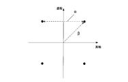
- FIG. 5 is a diagram for explaining the shift and scaling operations.
- Each black circle in the figure represents a modulation symbol.
- ⁇ represents the distance between adjacent modulation symbols, and ⁇ represents the shift from the reference point.
- QAM QAM is used as the modulation method, ⁇ and ⁇ have the following relationship.
- FIG. 5 shows the case of QPSK (4QAM). Therefore, the modulation symbol vector s can be expressed as follows.
- the vector c is an NT dimensional vector whose elements are 1 + j
- the vector s ⁇ is an NT dimensional vector having a reference point as an element. It has.
- the (m, k) -th output of the transmission signal candidate search unit 301 is set as s init (m, k).
- the first shift / scaling unit 401 shifts and scales the following equation using Equation (14) so as to facilitate subsequent quantization.
- the basis conversion unit 402 converts the base of the MIMO channel by multiplying the signal s ⁇ ' init (m, k) after the shift / scaling by a conversion matrix as shown in the following equation.
- the quantization unit 403 performs quantization by rounding the real part and the imaginary part of the signal after the base conversion to integer values.
- Q () represents quantization.
- the basis inverse transform unit 404 performs the inverse operation of the basis transform unit 402 on the quantized signal as shown in Expression (19).
- the second shift / scaling unit 405 performs the reverse operation of the first shift / scaling unit 401 as shown in Expression (20).
- S ⁇ (m, k) obtained is one transmission signal candidate. If s (m, k) is obtained for all m and k in addition to the signal x after MMSE detection, all searched transmission signal candidates can be obtained. With respect to the obtained transmission signal candidate, the determination unit obtains a transmission signal candidate that minimizes Equation (2).
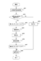
- FIG. 6 is a flowchart of the reception process of this embodiment.
- transmission signal candidate search section 301 uses the MMSE detection result as a starting point, searches for a transmission signal candidate in consideration of noise enhancement, and sends it to transmission signal candidate generation section 302.
- the first shift / scaling unit 401 of the transmission signal candidate generation unit 302 performs shifting and scaling based on the modulation scheme so that quantization is possible.
- the basis conversion unit 402 performs basis conversion of the channel matrix using the basis conversion matrix.
- the quantization unit 403 performs quantization so as to approximate an integer value.
- the base inverse transform unit 404 performs the inverse process of the base transform performed in step s603.
- step s606 the second shift / scaling unit 405 performs reverse processing of step s602 to obtain transmission signal candidates.
- step s607 the determination unit 303 calculates a metric using the transmission signal candidate, obtains a maximum likelihood sequence, and outputs it.
- the influence of the spatial correlation of the channel is suppressed, and then quantization is performed to obtain transmission signal candidates.
- the effect of spatial correlation was reduced based on lattice basis reduction.
- the probability that the transmission signal transmitted by the transmission apparatus remains as a transmission signal candidate is increased, so that the reception performance is improved.
- the present invention is not limited to the transmission signal search technique described in the first embodiment, but can be applied to any method that performs linear operation and quantization.
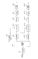
- FIG. 15 is a schematic block diagram of the transmission signal candidate generation unit 302 whose block order is changed.
- the transmission signal candidate generation unit 302 includes a base transform unit 2001, a first shift / scaling unit 2002, a quantization unit 2003, a second shift / scaling unit 2004, and a base inverse transform unit 2005.
- the basis conversion unit 2001 performs channel basis conversion on the output of the transmission signal candidate search unit 301 using the basis conversion matrix T.
- the first shift / scaling unit 2002 performs signal shifting and scaling so that the quantization in the subsequent-stage quantization unit 2003 can be simply rounded off.
- the quantization unit 2003 performs quantization such that the output of the first shift / scaling unit 2002 is rounded to an integer value for each of a real part and an imaginary part.
- the second shift / scaling unit 2004 performs the reverse operation of the shift and scaling performed by the first shift / scaling unit 2002.
- a base inverse transform unit 2005 performs the inverse transform of the base transform performed by the base transform unit 2001. Detailed description will be made using mathematical expressions.
- the basis conversion unit 2001 performs basis conversion as shown in the following equation.
- the first shift / scaling unit 2002 performs shifting and scaling as shown in the following equation.
- the quantization unit 2003 performs quantization by rounding the real part and the imaginary part of s T ′ (m, k) to integer values.
- the inverse transform of the base transform performed in the base transform unit 2001 is performed as in the following equation, and a transmission signal candidate is generated.
- FIG. 16 is a block diagram showing a configuration of the signal detection unit 203 in the present embodiment.
- the signal detection unit 203 includes a transmission signal candidate search unit 2101, a transmission signal candidate generation unit 2102, and a determination unit 2103.
- the transmission signal candidate search unit 2101 performs transmission signal search only for some of the elements of the signal x ⁇ after MMSE detection. Do. When the error of the signal x ⁇ after MMSE detection is small, an element with x ⁇ may be hard-decided.
- the diagonal element of P can be used. Assume that the Pth (i, i) (1 ⁇ i ⁇ NT) element P (i, i) of P is small. The result of hard decision on the i-th element of the signal x ⁇ after MMSE detection is s e (i), and the i-th column vector of H ⁇ is h ⁇ i . By transforming equation (1) and subtracting the component of s e (i) This y ′ can be used in place of y.
- the transmission signal candidate search unit 2101 can search for transmission signals other than the i-th element, and can reduce the amount of calculation for the search.
- the i-th element is output to the determination unit 2103 as the determination value s e (i).
- the transmission signal candidate generation unit 2102 performs shift, scaling, and quantization operations on transmission signals other than the i-th element.
- the basis conversion matrix is obtained from H ⁇ i instead of H ⁇ , and a basis conversion matrix of NT-1 rows and NT-1 columns is used.
- the determination unit 2103 calculates a metric using y ′, H ⁇ i , and the transmission signal candidate obtained by the transmission signal candidate generation unit 2102, obtains a transmission signal candidate having the smallest metric, and searches for a transmission signal candidate
- the determination value s e (i) obtained from the unit 2101 is output together.
- n may be changed depending on the modulation method.
- a bit log likelihood ratio obtained by soft-decision of the signal after MMSE detection can be used.
- determining in bit units if the absolute value of the bit log likelihood ratio is large, for example, if the bit log likelihood ratio is ⁇ , it is determined whether tanh (
- tanh () is a hyperbolic tangent function.
- determining in units of x ⁇ if it is determined that all bit log likelihood ratios obtained by soft-decision of the element are large, the element may be hard-decided.
- the signal size for performing the (quasi-) maximum likelihood detection is reduced. Therefore, the amount of calculation in transmission signal candidate search section 2101 to determination section 2103 can be reduced.
- transmission signal candidates are generated using the estimated channel matrix H ⁇ .
- the signal detection unit 203a in FIG. 2 is used by expanding H ⁇ and the received signal y as in the following equation.
- 0 NT is an NT dimension vector in which all elements are 0.
- the expanded channel matrix and the received signal are replaced with H ⁇ and y, respectively, and the same processing as in the first embodiment is performed. In this way, the orthogonalization of the base can be performed with higher accuracy, so that the reception performance is improved.
- This expanded channel matrix and received signal can also be used in the following embodiments.
- FIG. 7 is a schematic block diagram of the signal detection unit 203b.
- the signal detection unit 203b of the present embodiment includes a transmission signal candidate search unit 701, a candidate selection unit 702, a transmission signal candidate generation unit 703, and a determination unit 704.
- the transmission signal candidate search unit 701 is the same as the transmission signal candidate search unit 301 described in the first embodiment, the description thereof is omitted.
- Candidate selection section 702 outputs some of the signals searched by transmission signal candidate search section 701 to transmission signal candidate generation section 703, and quantizes all remaining signals or some remaining signals.
- the data is output to the determination unit 704.
- the transmission signal candidate generation unit 703 obtains transmission signal candidates by suppressing the influence of channel spatial correlation on the input signal.
- the determination unit 704 selects and outputs a transmission signal candidate having the smallest metric among the transmission signal candidates obtained from the candidate selection unit 702 and the transmission signal candidates obtained from the transmission signal candidate generation unit 703.
- the transmission signal candidate generation unit 703 has the same configuration as that of FIG.
- Candidate selection section 702 may output all of the signals searched by transmission signal candidate search section 701 to transmission signal candidate generation section 703, may output some signals, or may be a transmission signal candidate. It is not necessary to output a signal to the generation unit 703. When no signal is output, this corresponds to switching whether to suppress the influence of the spatial correlation of the channel. Thereby, the amount of calculation can be reduced by not performing the processing in the transmission signal candidate generation unit 703. Further, when the influence of the spatial correlation of the channel is suppressed for only some signals, it is not necessary to output all the remaining signals to the determination unit 704. This can reduce the amount of calculation in the determination unit 704 by further reducing the number of transmission signal candidates.
- a threshold value based on the spatial correlation of the channel can be used. If it is determined that the spatial correlation of the channel is large by the threshold value, the influence of the spatial correlation of the channel is suppressed. To do. If it is determined that the channel spatial correlation is small according to the threshold value, the influence of the channel spatial correlation is not suppressed.
- a channel spatial correlation value a distance between a transmission device and a reception device, a transmission antenna interval, a reception antenna interval, path angle information, and the like can be used. The spatial correlation value of the channel can be obtained from the channel matrix estimated in a certain period. The distance between the transmission device and the reception device can be easily obtained from the difference between the transmission power and the reception power.
- FIG. 8 is a flowchart of the reception process in this embodiment.
- the transmission signal candidate search unit 701 searches for transmission signal candidates in consideration of noise enhancement, starting from the detection result of MMSE.
- it is determined whether or not to reduce the influence of channel spatial correlation among the signals searched by candidate selection section 702.
- it is quantized by the candidate selection part 702 by step s809, and moves to step s808.
- the quantization in step s809 makes a hard decision.
- the transmission signal candidate searched by the candidate selection unit 702 is sent to the transmission signal candidate generation unit 703.
- step s803 the first shift / scaling unit 401 of the transmission signal candidate generation unit 703 performs shift scaling according to the modulation scheme in order to perform quantization in the subsequent stage.
- step s804 the basis conversion unit 402 performs basis conversion, and in step s805, the quantization unit 403 performs quantization to round each of the real part and the imaginary part to an integer value.
- step s806 the base inverse transform unit 404 performs the inverse transform of step s804, and in step s807, the second shift / scaling unit 405 restores the shift and scaling performed in step s803.
- step s808 the determination unit 704 obtains and outputs a maximum likelihood sequence from the transmission signal candidates obtained in step s807 and s809.
- a signal that suppresses the influence of the spatial correlation of the channel is selected, and the number of transmission signal candidates is further reduced. For this reason, the calculation amount in the transmission signal candidate production
- FIG. 9 is a block diagram showing the configuration of the transmission apparatus according to this embodiment.
- the transmission apparatus includes an encoding unit 901, a serial / parallel conversion unit 902, modulation units 903-1 to 903-NT, a pilot signal generation unit 904, mapping units 905-1 to 905-NT, and IFFT units 906-1 to 906-NT.
- the transmission bit is encoded by an encoding unit 901 with an error correction code such as a convolutional code, a turbo code, or an LDPC (Low Density Parity Check) code, and an encoded bit is obtained.
- the encoded bits are serial-parallel converted by the serial-parallel converter 902 and divided into sequences transmitted from the respective transmission antennas.
- Modulation sections 903-1 to 903-NT map the divided coded bits to modulation symbols such as PSK and QAM, and pilot signal generation section 904 generates a pilot signal that is a known signal on the transmission / reception side. Mapping sections 905-1 to 905-NT allocate modulation symbols and pilot signals to resources.
- mapping units 905-1 to 905-NT are respectively subjected to frequency time conversion by IFFT (Inverse Fourier Transform) units 906-1 to 906-NT, and GI (Guard Interval) insertion units.
- IFFT Inverse Fourier Transform
- GI Guard Interval
- a guard interval is inserted at 907-1 to 907-NT, and digital / analog conversion, waveform shaping, frequency conversion, etc. are performed at the radio transmission units 908-1 to 908-NT, and transmitted from each transmitting antenna (not shown). Is done.
- FIG. 10 is a block diagram showing the configuration of the receiving apparatus in this embodiment.
- the reception apparatus includes radio reception units 1001-1 to 1001-NR, GI removal units 1002-1 to 1002-NR, FFT (Fourier Transform) units 1003-1 to 1003-NR, channel estimation unit 1004, signal detection Unit 1005 and decoding unit 1006.
- Received waves received by NR reception antennas are subjected to frequency conversion, filtering, and analog / digital conversion by radio reception units 1001-1 to 1001-NR. Then, the guard interval is removed by the GI removal units 1002-1 to 1002-NR, and the time frequency is converted by the FFT units 1003-1 to 1003-NR.
- Channel estimation section 1004 estimates a frequency response using the pilot signal and obtains a channel estimation value.
- the signal detection unit 1005 performs MIMO detection on each subcarrier, and obtains a bit log likelihood ratio (LLR) indicating bit reliability.
- the decoding unit 1006 performs error correction decoding and obtains transmission bits.
- FIG. 11 is a schematic block diagram of the signal detection unit 1005.
- the signal detection unit 1005 includes a transmission signal candidate search unit 1101, a transmission signal candidate generation unit 1102, and a determination unit 1103. Since the transmission signal candidate search unit 1101 and the transmission signal candidate generation unit 1102 are the same as those in the first embodiment, description thereof will be omitted.
- the determination unit 1103 uses a transmission signal candidate to obtain a bit log likelihood ratio that is a maximum likelihood sequence when a soft decision is made as in the following equation.
- ⁇ k, n is the log likelihood ratio of the nth bit of the modulation symbol transmitted from the kth transmission antenna.
- the encoded bits are serially parallel converted into a data stream.
- the present invention is not limited to this, and the encoded bits may be obtained by encoding for each stream.
- FIG. 12 is a block diagram showing the configuration of the receiving apparatus in this embodiment.
- the receiving apparatus includes radio receiving sections 1201-1 to 1201-NR, GI removing sections 1202-1 to 1202-NR, FFT (Fourier Transform) sections 1203-1 to 1203-NR, channel estimation section 1204, signal detection A unit 1205 and a decoding unit 1206 are provided.
- the signal detection unit 1205 uses the decoded bit log likelihood ratio obtained from the decoding unit 1206 to obtain the bit log likelihood ratio with higher accuracy.
- the decoding unit 1206 outputs a bit log likelihood ratio to the signal detection unit 1205 if an error is detected as a result of error correction decoding and decoding has not been performed a prescribed number of times. When no error is detected or when a predetermined number of times of decoding is performed, a transmission bit obtained as a result of decoding is output.
- CRC Cyclic Redundancy Check
- FIG. 13 is a schematic block diagram of the signal detection unit 1205.
- the signal detection unit 1205 includes a transmission signal candidate search unit 1301, a transmission signal candidate generation unit 1302, and a determination unit 1303.
- the transmission signal candidate search unit 1301 searches for transmission signal candidates in the same manner as described in the above embodiment.
- the transmission signal candidate generation unit 1302 has the same configuration as that of FIG. 4 and generates a transmission signal candidate while suppressing the influence of spatial correlation.
- the determination unit 1303 uses the bit log likelihood ratio obtained from the decoding unit 1206 to obtain the bit log likelihood ratio after MIMO detection as follows.
- p (b k, n ) represents the occurrence probability of b k, n representing the nth bit of the modulation symbol transmitted from the kth transmission antenna.
- p (b k, n ) can be obtained from the bit log likelihood ratio obtained from the decoding unit 1206.
- Transmission signal candidate search section 1301 may obtain the expected value of the modulation symbol from the bit log likelihood ratio and search for the transmission signal using that as a starting point.
- the bit log likelihood ratio is input to the transmission signal candidate search unit 1301.
- a candidate having a large metric may be deleted from transmission signal candidates in the next iterative process. Note that when the default number of decodings is set to 1, it is the same as in the fifth embodiment.
- FIG. 14 is a flowchart of the reception process of this embodiment.
- transmission signal candidate search section 1301 starts from the MMSE detection result, searches for a transmission signal candidate in consideration of noise enhancement, and sends the result to transmission signal candidate generation section 1302.
- the first shift / scaling unit 401 of the transmission signal candidate generation unit 1302 performs shifting and scaling based on the modulation scheme so that quantization is possible.
- the basis conversion unit 402 performs basis conversion of the channel matrix using the basis conversion matrix.
- the quantization unit 403 performs quantization so as to approximate an integer value.
- the base inverse transform unit 404 performs the inverse transform of the base transform performed in step s1403.
- step s1406 the second shift / scaling unit 405 performs reverse processing of step s1402 to obtain transmission signal candidates.
- step s1407 the determination unit 1303 performs soft decision maximum likelihood detection using the transmission signal candidate and the bit log likelihood ratio of the decoding result.
- step s1408 the decoding unit 1206 performs error correction decoding on the bit log likelihood ratio obtained as a result of soft decision maximum likelihood detection.
- step s1409 the decoding unit 1206 determines whether an error has not been detected or a predetermined number of decoding processes have been performed. If an error has been detected and the predetermined number of decoding processes have not been performed, The process moves to s1407. When no error is detected or the specified number of times of processing has been performed, the transmission bit obtained by decoding is output and the reception processing is terminated.
- the program that operates in the receiving apparatus is a program that controls the CPU and the like (a program that causes a computer to function) so as to realize the functions of the above-described embodiments according to the present invention.
- Information handled by these devices is temporarily stored in the RAM at the time of processing, then stored in various ROMs and HDDs, read out by the CPU, and corrected and written as necessary.
- a recording medium for storing the program a semiconductor medium (for example, ROM, nonvolatile memory card, etc.), an optical recording medium (for example, DVD, MO, MD, CD, BD, etc.), a magnetic recording medium (for example, magnetic tape, Any of a flexible disk etc. may be sufficient.
- the processing is performed in cooperation with the operating system or other application programs.
- the functions of the invention may be realized.
- the program when distributing to the market, can be stored in a portable recording medium for distribution, or transferred to a server computer connected via a network such as the Internet.
- the storage device of the server computer is also included in the present invention.
- Each functional block of the receiving apparatus may be individually formed as a chip, or a part or all of them may be integrated into a chip. When each functional block is integrated, an integrated circuit controller for controlling them is added.
- the method of circuit integration is not limited to LSI, and may be realized by a dedicated circuit or a general-purpose processor.
- an integrated circuit based on the technology can also be used.
Landscapes
- Engineering & Computer Science (AREA)
- Computer Networks & Wireless Communication (AREA)
- Signal Processing (AREA)
- Physics & Mathematics (AREA)
- Mathematical Physics (AREA)
- Artificial Intelligence (AREA)
- Radio Transmission System (AREA)
Abstract
チャネルの空間相関が高くなった場合の性能劣化を軽減できる受信装置、受信方法、及び受信プログラムを提供する。 送信信号候補探索部301は、MIMO信号検出において受信性能が劣化する方向に送信信号を探索する。送信信号候補生成部302で、チャネルの空間相関による劣化を抑えながら送信信号候補を生成する。判定部303では、送信信号候補生成部302で生成された送信信号候補を用いて最尤系列を求める。最尤系列は、メトリックを計算し、メトリックが最小となる送信信号候補として求められる。
Description
本発明は、MIMO伝送によって通信を行う受信装置、受信方法、及び受信プログラムに関する。
近年の無線通信の分野では、複数の送受信アンテナを用い、周波数帯域幅を広げずに高速伝送が可能なMIMO(Multiple Input Multiple Output)伝送が多くのシステムで採用されている。一般に、MIMO伝送では、複数のデータストリームを同一周波数を用いて伝送するため、受信装置でMIMO信号検出が必要となる。
MIMO信号検出技術の中で、最適な検出技術として最尤検出(MLD:Maximum Likelihood Detection)がある。これは全ての送信信号候補のうち、尤度関数を最大にするものを検出する技術である。送信信号候補は変調方式のコンスタレーション数や送信ストリーム数に従って指数関数的に増大するため、MLDは計算量が非常に多くなるという問題がある。
非特許文献1には、効率的に送信信号候補を削減することでMLDの計算量を削減する技術が記載されている。非特許文献1では、伝送特性は良くないが計算量が非常に少ない線形検出であるMMSE(Minimum Mean Square Error)検出が誤る要因である雑音強調の方向に送信信号候補を探索することで、MLDからの性能劣化を抑えながらも計算量を大幅に低減している。
Liming Zheng, Kazuhiko Fukawa, Hiroshi Suzuki, Satoshi Suyama, "Near-Optimal Siganl Detection in Noise Enhancement Subspace for Spatially Correlated MIMO Channels", 電子情報通信学会総合大会B-5-46、2011年3月。
しかしながら、非特許文献1に記載の技術は、MIMOチャネルの空間相関が高くなった場合、受信性能が著しく劣化してしまうという問題がある。
本発明は、このような事情を鑑みてなされたものであり、その目的は、MIMOチャネルの空間相関が高くなった場合の性能劣化を軽減できる受信装置、受信方法、及び受信プログラムを提供するものである。
本発明は、MIMO伝送によって通信を行なう受信装置であって、雑音強調を考慮して送信信号候補の探索を行う送信信号候補探索部と、前記探索した信号に対して、チャネルの空間相関の影響を抑圧して送信信号候補を生成する送信信号候補生成部と、生成された前記送信信号候補を用いて最尤系列を求める判定部と、を備えることを特徴とする。
前記送信信号候補生成部は、変調方式に基づいてシフト及びスケーリングを行う第1のシフト・スケーリング部と、基底変換行列を乗算して基底変換を行う基底変換部と、整数値に丸める量子化部と、前記基底変換部の逆操作を行う基底逆変換部と、前記第1のシフト・スケーリング部の逆操作を行って前記送信信号候補を生成する第2のシフト・スケーリング部と、を備えることを特徴とする。
また、前記送信信号候補生成部は、基底変換行列を乗算して基底変換を行う基底変換部と、変調方式に基づいてシフト及びスケーリングを行う第1のシフト・スケーリング部と、整数値に丸める量子化部と、前記第1のシフト・スケーリング部の逆操作を行う第2のシフト・スケーリング部と、前記基底変換部の逆操作を行って前記送信信号候補を生成する基底逆変換部と、を備えることを特徴とする。
これら前記送信信号候補生成部は、拡張したチャネル行列及び受信信号を用いて前記送信信号候補を生成することを特徴とする。
また、前記送信信号候補探索部は、雑音強調及びIQ平面で表現される任意の位置を考慮して送信信号候補の探索を行うことを特徴とする。
また、前記送信信号候補探索部は、雑音強調及び変調方式を考慮して送信信号候補の探索を行うことを特徴とする。
また、前記送信信号候補探索部は、線形検出結果のうち、一部の信号に対しては対応する送信信号候補の探索を行い、残りの信号は硬判定して出力することを特徴とする。
ここで、この前記送信信号候補生成部は、前記一部の信号に対応するチャネルを用いて送信信号候補を生成することを特徴とする。
ここで、この前記送信信号候補生成部は、前記一部の信号に対応するチャネルを用いて送信信号候補を生成することを特徴とする。
また、前記探索した信号に対して、チャネルの空間相関に基づいて空間相関の影響を抑圧するか否かの選択を行なう候補選択部をさらに備えることを特徴とする。
前記候補選択部は、空間相関の影響を抑圧しない信号を量子化して送信信号候補を生成し、前記判定部は、前記送信信号候補生成部が生成した送信信号候補、及び、前記候補選択部が生成した送信信号候補を用いて最尤系列を求めることを特徴とする。
また、前記受信装置は、誤り訂正復号を行なう復号部をさらに備え、前記判定部は、前記最尤系列のビット対数尤度比を求め、前記復号部は、前記最尤系列のビット対数尤度比に対して誤り訂正復号を行なうことを特徴とする。
さらに前記判定部は、前記送信信号候補及び前記復号後のビット対数尤度比から前記最尤系列のビット対数尤度比を求めることを特徴とする。
また、本発明は、MIMO伝送によって通信を行なう受信装置における受信方法であって、雑音強調を考慮して送信信号候補の探索を行なう送信信号候補探索過程と、前記探索した信号に対して、チャネルの空間相関の影響を抑圧して送信信号候補を生成する送信信号候補生成過程と、生成された前記送信信号候補から最尤系列を求める判定過程と、を有することを特徴とする。
また、本発明は、コンピュータに、前記受信方法の各過程を実行させるための受信プログラムである。
このように本発明は、信号探索の後段にMIMOチャネルの空間相関による劣化を抑圧する処理を行って、送信信号候補を生成しているので、チャネルの空間相関が高くなった場合でも、その性能劣化を抑えることができる。
以下、図面を用いて本発明の詳細を説明していく。
以下の実施形態では送信アンテナ数をNT本、受信アンテナ数をNR本とする。また、送信データストリームは各送信アンテナから送信されるものとして、つまりデータストリーム数と送信アンテナ数は等しいものと説明するが、本発明はこれに限らず、送信アンテナ数よりも少ない複数のデータストリームが送信される場合も本発明に含まれる。
以下の実施形態では送信アンテナ数をNT本、受信アンテナ数をNR本とする。また、送信データストリームは各送信アンテナから送信されるものとして、つまりデータストリーム数と送信アンテナ数は等しいものと説明するが、本発明はこれに限らず、送信アンテナ数よりも少ない複数のデータストリームが送信される場合も本発明に含まれる。
(第1の実施形態)
図1は、本実施形態の送信装置の構成を示すブロック図である。
送信装置は、変調部101-1~101-NT、パイロット信号生成部102、マッピング部103、無線送信部104-1~104-NTを備える。
図1は、本実施形態の送信装置の構成を示すブロック図である。
送信装置は、変調部101-1~101-NT、パイロット信号生成部102、マッピング部103、無線送信部104-1~104-NTを備える。
変調部は101-1~101-NTは、送信ビットをPSK(位相変調:Phase Shift Keying)、QAM(直交振幅変調:Quadrature Amplitude Modulation)といった変調シンボルにマッピングする。パイロット信号生成部102は、送受信装置で既知の信号であるパイロット信号を生成する。マッピング部103は変調シンボル及びパイロット信号をリソースに配置する。ここでリソースとは周波数及び時間で定義される領域であるが、本実施形態では狭帯域伝送における適用例を示すため、本実施形態におけるリソースとは時間を示す。マッピング部103の出力は、無線送信部104-1~104-NTでデジタル・アナログ変換、波形整形、周波数変換等を行ない、NT本の送信アンテナ(図示せず)から送信される。
図2は、本実施形態における受信装置の構成を示すブロック図である。
受信装置は、無線受信部201-1~201-NR、チャネル推定部202、信号検出部203を備える。
受信装置は、無線受信部201-1~201-NR、チャネル推定部202、信号検出部203を備える。
NR本の受信アンテナ(図示せず)で受信された受信波は、無線受信部201-1~201-NRで周波数変換、フィルタリング、アナログ・デジタル変換され、受信信号として出力される。チャネル推定部202は、パイロット信号を用いてチャネル推定を行ってチャネル推定値を求める。信号検出部203は受信信号及びチャネル推定値を用いて送信ビットを検出する。
図3は、信号検出部203aの概略ブロック図である。
信号検出部203aは、送信信号候補探索部301、送信信号候補生成部302、判定部303を備える。送信信号候補探索部301は、MIMO信号検出において受信性能が劣化する方向に送信信号を探索する。例えば、線形検出技術のであるZF(Zero Forcing)検出やMMSE(Minimum Mean Square Error)検出の場合、雑音強調の方向に送信信号候補を探索する。従来技術では送信信号候補探索部301の出力を量子化して送信信号候補を求めていたが、本発明では、送信信号候補生成部302で、チャネルの空間相関による劣化を抑えながら送信信号候補を生成する。判定部303では、送信信号候補生成部302で生成された送信信号候補を用いて最尤系列を求める。最尤系列は、メトリックを計算し、メトリックが最小となる送信信号候補が求められる。例えば受信信号を式(1)と表すと、メトリックは式(2)のように求められる。
信号検出部203aは、送信信号候補探索部301、送信信号候補生成部302、判定部303を備える。送信信号候補探索部301は、MIMO信号検出において受信性能が劣化する方向に送信信号を探索する。例えば、線形検出技術のであるZF(Zero Forcing)検出やMMSE(Minimum Mean Square Error)検出の場合、雑音強調の方向に送信信号候補を探索する。従来技術では送信信号候補探索部301の出力を量子化して送信信号候補を求めていたが、本発明では、送信信号候補生成部302で、チャネルの空間相関による劣化を抑えながら送信信号候補を生成する。判定部303では、送信信号候補生成部302で生成された送信信号候補を用いて最尤系列を求める。最尤系列は、メトリックを計算し、メトリックが最小となる送信信号候補が求められる。例えば受信信号を式(1)と表すと、メトリックは式(2)のように求められる。

ただし、yはNR次元受信信号ベクトル、HはNR行NT列チャネル行列、sはNT次元送信信号ベクトル、nはNR次元雑音ベクトル、H^はNR行NT列チャネル推定値、sbはビット系列b=[b1,1,…,bk,n,…,bNT,N]で決めるNT次元送信信号候補ベクトルである。なお、Nは変調方式のコンスタレーション数をMとすると、N=log2Mである。
MMSE検出を用いた場合の送信信号候補探索部301の詳細を、数式を用いて説明する。MMSE検出は次のようなNR行NT列の重み行列を用いる。

ただし、上付きのHは複素共役転置行列、σn
2は平均雑音電力、INTはNT行NT列の単位行列を表す。ここで、行列Pはσn
2Pが誤差の共分散行列となるNT行NT列のエルミート行列である。雑音強調を考慮して送信信号の探索を行なうために、Pの固有値分解を次式のように行なう。

ただし、VはNT行NT列のユニタリ行列、Dは固有値λ1~λNTを対角要素にもつ対角行列である。なお、固有値の大きさはλ1≧λ2≧・・・≧λNTであるとする。また、Pが正定値行列のため、固有値は全て正、即ちλNT>0である。値の大きい固有値が性能劣化を引き起こすと考えられる。このとき探索後の信号s^initは次式のように求めることができる。

ただし、x^はMMSE検出後の信号である。また、Npは1≦Np≦NTであり、信号候補探索で考慮する固有値の数を表し、vkは行列Vの第k列ベクトルであり、(A)kはベクトルAの第k要素を表す。また、b(m)は変調シンボルの1つを表す。このため、1≦m≦Mであるので、b(m)はM通り存在する。s^initはM×NT通り存在するため、x^も加えるとM×NT+1個の信号を得ることができる。なお、a^(m,k)は式(8)のように変調方式のコンスタレーションを考慮して求める代わりにa^(m,k)の各要素をランダムな変数に設定することもできる。これにより変調方式のコンスタレーションではなく、IQ平面で表現される任意の位置を考慮することができる。なお、IQ平面は、横軸にI軸(同相(in phase)軸)、縦軸にQ軸(直交(quadrature phase)軸)を持つ平面である。ランダムな変数は例えば平均零、分散σn
2の複素ガウス分布に従う確率変数として設定することができる。ランダムな変数を用いる場合、s^initの個数はM×NT+1以上にすることも可能であるし、M×NT+1以下にすることも可能である。s^initの個数は、減らせば演算量を削減でき、増やせばビット誤り率など受信性能を向上させることができる。探索した信号を量子化すると送信信号候補が得られるが、チャネルの空間相関が高い場合、正しい送信信号が送信信号候補に含まれる確率が低くなってしまう。そのため、送信信号候補生成部302でチャネルの空間相関の影響を抑えながら送信信号候補を生成する。
送信信号候補生成部302の詳細を、数式を用いて説明する。
送信信号候補生成部302では、LR(格子基底縮小:Lattice Reduction)に基づいて空間相関による劣化を抑圧する。LRは、チャネル行列Hの基底を直交に近い状態に変換することで、チャネル行列HをMIMO分離しやすい形に変換する。NT行NT列の基底変換行列をTとすると、H’=H^Tを用いることになる。なお、行列Tは、各要素の実部、虚部が共に整数となる複素数で、|det(T)|=1となるユニモジュラ行列(unimodular matrix)である。行列Tは、例えば、公知技術であるLLL(Lenstra, Lenstra, Lovasz)アルゴリズム等を用いて求めることができる。なお、det(・)は行列式を表す。式(3)において、H^をH’に置換した重み行列をW’とする。LRによるMMSE検出は、W’を用いて次式のように行われる。
送信信号候補生成部302では、LR(格子基底縮小:Lattice Reduction)に基づいて空間相関による劣化を抑圧する。LRは、チャネル行列Hの基底を直交に近い状態に変換することで、チャネル行列HをMIMO分離しやすい形に変換する。NT行NT列の基底変換行列をTとすると、H’=H^Tを用いることになる。なお、行列Tは、各要素の実部、虚部が共に整数となる複素数で、|det(T)|=1となるユニモジュラ行列(unimodular matrix)である。行列Tは、例えば、公知技術であるLLL(Lenstra, Lenstra, Lovasz)アルゴリズム等を用いて求めることができる。なお、det(・)は行列式を表す。式(3)において、H^をH’に置換した重み行列をW’とする。LRによるMMSE検出は、W’を用いて次式のように行われる。

式(12)より、W’を用いてMMSE検出するものと、Wを用いてMMSE検出したものに変換行列の逆行列T-1を左から乗算するものは、近似的に等価である。このことを利用すると、送信信号候補探索部301はMMSE検出結果を起点とし線形操作を行っているので、送信信号候補生成部302は、Tを用いてチャネルの空間相関の影響を軽減して送信信号候補を求めることができる。なお、ZF検出の場合も同様である。
図4は、送信信号候補生成部302の概略ブロック図である。
送信信号候補生成部302は、第1のシフト・スケーリング部401、基底変換部402、量子化部403、基底逆変換部404、第2のシフト・スケーリング部405を備える。
送信信号候補生成部302は、第1のシフト・スケーリング部401、基底変換部402、量子化部403、基底逆変換部404、第2のシフト・スケーリング部405を備える。
第1のシフト・スケーリング部401は、後段の量子化部403での量子化が単純な四捨五入ですむように信号のシフト及びスケーリングを行なう。詳細は後述する。基底変換部402は、上述のような行列Tを用いてHの基底変換を行なう。量子化部403では、基底変換部402の出力を量子化する。量子化は整数値に丸めれば良い。基底逆変換部404は基底変換部402で行った基底変換の逆変換を行なう。第2のシフト・スケーリング部405は第1のシフト・スケーリング部401の逆操作を行なう。第2のシフト・スケーリング部405の出力は送信信号候補となる。
送信信号候補生成部302の詳細を数式を用いて説明する。
図5はシフト及びスケーリング操作を説明するための図である。図中の黒丸はそれぞれ変調シンボルを表している。また、αを隣接変調シンボル間の距離、βを基準点からのシフトを表すとする。変調方式にQAMを用いた場合、αとβには次のような関係がある。
図5はシフト及びスケーリング操作を説明するための図である。図中の黒丸はそれぞれ変調シンボルを表している。また、αを隣接変調シンボル間の距離、βを基準点からのシフトを表すとする。変調方式にQAMを用いた場合、αとβには次のような関係がある。

ただし、jは虚数単位で、j2=-1である。図5はQPSK(4QAM)の場合である。
従って、変調シンボルベクトルsは次のように表すことができる。
従って、変調シンボルベクトルsは次のように表すことができる。

なお、ベクトルcは各要素が1+jのNT次元ベクトル、ベクトルs-は基準点を要素に持つNT次元ベクトルであり、その要素は、実部と虚部でそれぞれ式(15)のどれかの値をもつ。

例えばQPSK(4QAM)の場合、M=4、であるので、式(15)は[-1、0]となる。従って、s-の要素は

となる。
送信信号候補探索部301の出力の(m,k)番目をs^init(m,k)とする。第1のシフト・スケーリング部401は、後段の量子化が容易になるように式(14)を利用して次式のようにシフト及びスケーリングする。

基底変換部402は、シフト・スケーリング後の信号s^’init(m,k)に対し、次式のように変換行列を乗算することで、MIMOチャネルの基底を変換する。

量子化部403は、基底変換後の信号の実部、虚部をそれぞれ整数値に丸めることで量子化を行なう。

なお、Q()は量子化を表す。基底逆変換部404は、量子化後の信号に対し、式(19)のように基底変換部402の逆操作を行なう。

第2のシフト・スケーリング部405は式(20)のように第1のシフト・スケーリング部401の逆操作を行なう。

求められたs^(m,k)は1つの送信信号候補となる。MMSE検出後の信号x^に加えて、全てのm,kについてs^(m,k)を求めれば、探索した全ての送信信号候補を求められる。求められた送信信号候補は、判定部で式(2)が最小となる送信信号候補のが求められる。
図6は、本実施形態の受信処理のフローチャートである。
ステップs601では、送信信号候補探索部301がMMSEの検出結果を起点とし、雑音強調を考慮して送信信号候補を探索し、送信信号候補生成部302に送る。ステップs602では、送信信号候補生成部302の第1のシフト・スケーリング部401が、量子化できるように変調方式に基づいてシフト及びスケーリングを行う。ステップs603では、基底変換部402が基底変換行列によりチャネル行列の基底変換を行う。ステップs604では、量子化部403が、整数値に近似するような量子化を行う。ステップs605では、基底逆変換部404がステップs603で行われた基底変換の逆処理を行う。ステップs606では、第2のシフト・スケーリング部405が、ステップs602の逆処理を行って送信信号候補を求める。ステップs607では、判定部303が送信信号候補を用いてメトリックを計算し、最尤系列を求めて出力する。
ステップs601では、送信信号候補探索部301がMMSEの検出結果を起点とし、雑音強調を考慮して送信信号候補を探索し、送信信号候補生成部302に送る。ステップs602では、送信信号候補生成部302の第1のシフト・スケーリング部401が、量子化できるように変調方式に基づいてシフト及びスケーリングを行う。ステップs603では、基底変換部402が基底変換行列によりチャネル行列の基底変換を行う。ステップs604では、量子化部403が、整数値に近似するような量子化を行う。ステップs605では、基底逆変換部404がステップs603で行われた基底変換の逆処理を行う。ステップs606では、第2のシフト・スケーリング部405が、ステップs602の逆処理を行って送信信号候補を求める。ステップs607では、判定部303が送信信号候補を用いてメトリックを計算し、最尤系列を求めて出力する。
このように、第1の実施形態では、送信信号候補の探索後、チャネルの空間相関の影響を抑圧してから、量子化し、送信信号候補を求めるようにした。具体的には、格子基底縮小に基づいて空間相関の影響を軽減した。これにより、送信装置で送信された送信信号が、送信信号候補に残る確率が上がるため、受信性能が向上する。
なお、上記第1の実施形態で説明した送信信号探索技術に限らず、線形操作と量子化を行なう方式であれば、本発明を適用することができる。
(第1の実施形態の変形例)
上記第1の実施形態で図4を用いて説明した送信信号候補生成部302は、ブロックの順序を変更しても等価な信号を生成することができる。図15はブロックの順序を変更した送信信号候補生成部302の概略ブロック図である。送信信号候補生成部302は基底変換部2001、第1のシフト・スケーリング部2002、量子化部2003、第2のシフト・スケーリング部2004、基底逆変換部2005を備える。基底変換部2001では送信信号候補探索部301の出力に対し、基底変換行列Tを用いてチャネルの基底変換を行う。第1のシフト・スケーリング部2002は、後段の量子化部2003での量子化が単純な四捨五入ですむように信号のシフト及びスケーリングを行う。量子化部2003は第1のシフト・スケーリング部2002の出力を実部、虚部のそれぞれを整数値に丸めるような量子化を行う。第2のシフト・スケーリング部2004は、第1のシフト・スケーリング部2002で行われたシフト及びスケーリングの逆操作を行う。基底逆変換部2005は基底変換部2001で行われた基底変換の逆変換を行う。数式を用いて詳細説明する。
基底変換部2001は次式のように基底変換を行う。
上記第1の実施形態で図4を用いて説明した送信信号候補生成部302は、ブロックの順序を変更しても等価な信号を生成することができる。図15はブロックの順序を変更した送信信号候補生成部302の概略ブロック図である。送信信号候補生成部302は基底変換部2001、第1のシフト・スケーリング部2002、量子化部2003、第2のシフト・スケーリング部2004、基底逆変換部2005を備える。基底変換部2001では送信信号候補探索部301の出力に対し、基底変換行列Tを用いてチャネルの基底変換を行う。第1のシフト・スケーリング部2002は、後段の量子化部2003での量子化が単純な四捨五入ですむように信号のシフト及びスケーリングを行う。量子化部2003は第1のシフト・スケーリング部2002の出力を実部、虚部のそれぞれを整数値に丸めるような量子化を行う。第2のシフト・スケーリング部2004は、第1のシフト・スケーリング部2002で行われたシフト及びスケーリングの逆操作を行う。基底逆変換部2005は基底変換部2001で行われた基底変換の逆変換を行う。数式を用いて詳細説明する。
基底変換部2001は次式のように基底変換を行う。

第1のシフト・スケーリング部2002は、次式のようにシフト及びスケーリングを行う。

ここで、式(A2)で得られるsT’(m,k)と式(17)で得られるsT’(m,k)は等価となる。
量子化部2003は、sT’(m,k)の実部、虚部をそれぞれ整数値に丸めることで量子化を行う。
量子化部2003は、sT’(m,k)の実部、虚部をそれぞれ整数値に丸めることで量子化を行う。

第2のシフト・スケーリング部2004では、第1のシフト・スケーリング部2002で行われたシフト及びスケーリングの逆操作が次式のように行われる。

基底逆変換部2005では、基底変換部2001で行われた基底変換の逆変換が次式のように行われ、送信信号候補が生成される。

ここで、式(A5)で得られる送信信号候補と式(20)で得られる送信信号候補は等価となる。
なお、基底変換部2001と第1のシフト・スケーリング部2002の入れ替え、及び、第2のシフト・スケーリング部2004と基底逆変換部2005の入れ替えは独立に行うことができる。
(第2の実施形態)
本実施形態と第1の実施形態の違いは図2の信号検出部203であるので、その他の説明は省略する。図16は本実施形態における信号検出部203の構成を示すブロック図である。信号検出部203は、送信信号候補探索部2101、送信信号候補生成部2102、判定部2103を備える。送信信号候補探索部2101は、第1の実施形態の図3で説明した送信信号候補探索部301とは異なり、MMSE検出後の信号x^の要素のうち、一部の要素のみ送信信号探索を行う。MMSE検出後の信号x^の誤差が小さい場合には、x^のある要素を硬判定してもよい。MMSE検出の誤差は式(4)のPの対角要素に比例するので、例えばPの対角要素を用いることができる。今、Pの第(i,i)(1≦i≦NT)要素P(i,i)が小さいとする。MMSE検出後の信号x^の第i要素を硬判定した結果をse(i)とし、H^の第i列ベクトルをh^iとする。式(1)を変形し、se(i)の成分を差し引くと

となり、このy’をyの代わりに用いることができる。またH^の代わりに、H^からh^iを抜いたNR行NT-1列のチャネル行列H^iを用いれば、送信アンテナ数が実質NT-1になり、第i要素以外の送信信号を検出することと等価になる。このようにすれば、送信信号候補探索部2101は第i要素以外の送信信号を探索するようにでき、探索にかかる演算量を削減することができる。なお、第i要素は判定値se(i)として判定部2103に出力する。送信信号候補生成部2102は、第i要素以外の送信信号に対してシフト及びスケーリング、量子化の操作を行う。具体的には、基底変換行列はH^ではなくH^iから求め、NT-1行NT-1列の基底変換行列を用いる。判定部2103は、y’、H^i、及び、送信信号候補生成部2102で得られた送信信号候補を用いてメトリックを計算し、メトリックが最小となる送信信号候補を求め、送信信号候補探索部2101から得られた判定値se(i)と合わせて出力する。
本実施形態と第1の実施形態の違いは図2の信号検出部203であるので、その他の説明は省略する。図16は本実施形態における信号検出部203の構成を示すブロック図である。信号検出部203は、送信信号候補探索部2101、送信信号候補生成部2102、判定部2103を備える。送信信号候補探索部2101は、第1の実施形態の図3で説明した送信信号候補探索部301とは異なり、MMSE検出後の信号x^の要素のうち、一部の要素のみ送信信号探索を行う。MMSE検出後の信号x^の誤差が小さい場合には、x^のある要素を硬判定してもよい。MMSE検出の誤差は式(4)のPの対角要素に比例するので、例えばPの対角要素を用いることができる。今、Pの第(i,i)(1≦i≦NT)要素P(i,i)が小さいとする。MMSE検出後の信号x^の第i要素を硬判定した結果をse(i)とし、H^の第i列ベクトルをh^iとする。式(1)を変形し、se(i)の成分を差し引くと
なお、ここではPの対角要素のうち、小さいものが1つある場合について説明したが、本発明はこれに限らず、複数の場合も同様に適用できる。
また、MMSE検出後の信号の要素のうち、誤差が小さいかどうかを判断するには、システムが要求する通信品質(ビットやパケットの誤り率など)を満たせるかどうかで判断することができる。例えば、所要品質が満たせるSNR(信号電力対雑音電力比:Signal to Noise Power Ratio)をn(真値)としたとき、σn
2P(i,i)<1/nとなった要素を硬判定すればよい。なお、nは変調方式によって変えてもよい。
また、MMSE検出後の信号の誤差が小さいかどうかを判断するには、MMSE検出後の信号を軟判定して得られるビット対数尤度比を用いることができる。ビット単位で判断する場合は、ビット対数尤度比の絶対値が大きいもの、例えば、ビット対数尤度比をλとすると、tanh(|λ|)が1に近似できる値かどうかを判断すれば良い。tanh()は双曲線正接関数である。x^の要素単位で判断する場合は、その要素を軟判定して得られるビット対数尤度比が全て大きいと判断されれば、その要素を硬判定すればよい。
このように上記本実施形態では、(準)最尤検出を行う信号サイズを小さくするようにした。このため、送信信号候補探索部2101~判定部2103における演算量を削減することができる。
(第3の実施形態)
第1の実施形態では、推定したチャネル行列H^を用いて送信信号候補を生成していた。本実施形態では、図2の信号検出部203aで次式のようにH^及び受信信号yを拡張したものを用いる。
第1の実施形態では、推定したチャネル行列H^を用いて送信信号候補を生成していた。本実施形態では、図2の信号検出部203aで次式のようにH^及び受信信号yを拡張したものを用いる。
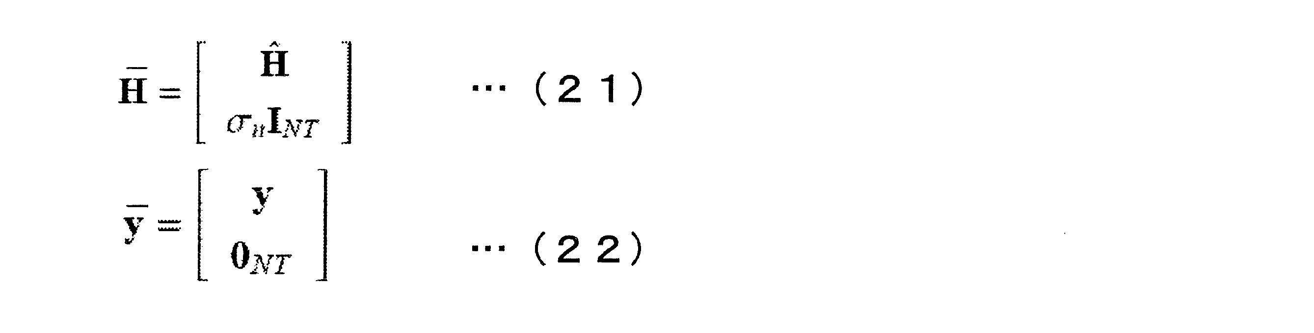
ただし、0NTは全ての要素が0のNT次元ベクトルである。このように拡張したチャネル行列及び受信信号を、それぞれH^及びyに置き換えて第1の実施形態と同様に行なう。このようにすると、基底の直交化がより精度よく行えるので、受信性能が向上する。この拡張したチャネル行列及び受信信号は、以降の実施形態でも用いることができる。
(第4の実施形態)
本実施形態は、上記第1の実施形態とは信号検出部203が異なるので、その他の説明は省略する。図7は、信号検出部203bの概略ブロック図である。
本実施形態の信号検出部203bは、送信信号候補探索部701、候補選択部702、送信信号候補生成部703、判定部704を備える。
本実施形態は、上記第1の実施形態とは信号検出部203が異なるので、その他の説明は省略する。図7は、信号検出部203bの概略ブロック図である。
本実施形態の信号検出部203bは、送信信号候補探索部701、候補選択部702、送信信号候補生成部703、判定部704を備える。
送信信号候補探索部701は、第1の実施形態で説明した送信信号候補探索部301と同様であるので説明は省略する。候補選択部702は、送信信号候補探索部701が探索した信号のうち、一部を送信信号候補生成部703に出力し、残りの全ての信号、もしくは、残りの一部の信号は量子化して判定部704に出力する。送信信号候補生成部703は、第1の実施形態と同様に、入力された信号に対し、チャネルの空間相関の影響を抑圧して送信信号候補を求める。判定部704は、候補選択部702から得られる送信信号候補と送信信号候補生成部703から得られる送信信号候補のうち、メトリックが最小となる送信信号候補を選択して出力する。送信信号候補生成部703は、図4の構成と全く同じである。
候補選択部702は、送信信号候補探索部701が探索した信号のうち、全てを送信信号候補生成部703に出力してもよいし、一部の信号を出力してもよいし、送信信号候補生成部703に信号を出力しなくてもよい。信号を出力しない場合は、チャネルの空間相関の影響を抑圧するかどうかの切り替えに相当する。これにより送信信号候補生成部703での処理を行わないことで、計算量を低減することができる。また、一部の信号のみチャネルの空間相関の影響を抑圧する場合、残りの信号の全てを判定部704に出力する必要はない。これは送信信号候補の数をさらに減らすことで、判定部704における計算量を減らすことができる。候補選択部702による選択の基準は、チャネルの空間相関に基づいたしきい値を用いることができ、しきい値によってチャネルの空間相関が大きいと判断した場合は、チャネルの空間相関の影響を抑圧する。しきい値によってチャネルの空間相関が小さいと判断した場合は、チャネルの空間相関の影響は抑圧しない。しきい値にはチャネルの空間相関値、送信装置と受信装置の距離、送信アンテナ間隔、受信アンテナ間隔、パスの角度情報などを用いることができる。チャネルの空間相関値は、ある期間に推定したチャネル行列から求めることができる。送信装置と受信装置の距離は、送信電力と受信電力の差から簡易的に求めることができる。
図8は、本実施形態における受信処理のフローチャートである。
ステップs801では、送信信号候補探索部701がMMSEの検出結果を起点として、雑音強調を考慮して送信信号候補を探索する。ステップs802では、候補選択部702が探索した信号のうち、チャネルの空間相関の影響を軽減するかどうかを判断する。軽減しない場合は、ステップs809で候補選択部702により量子化されてステップs808に移る。ステップs809における量子化は硬判定を行なう。軽減する場合は、候補選択部702が探索した送信信号候補を送信信号候補生成部703に送る。ステップs803では、後段で量子化するために送信信号候補生成部703の第1のシフト・スケーリング部401が、変調方式に従ってシフト・スケーリングを行なう。ステップs804では、基底変換部402が基底変換を行い、ステップs805で量子化部403が実部、虚部のそれぞれを整数値にまるめる量子化を行なう。ステップs806では、基底逆変換部404がステップs804の逆変換を行い、ステップs807では、第2のシフト・スケーリング部405が、ステップs803で行われたシフト、スケーリングを元に戻す。ステップs808は、判定部704がステップs807やステップs809で得られた送信信号候補から最尤系列を求めて出力する。
ステップs801では、送信信号候補探索部701がMMSEの検出結果を起点として、雑音強調を考慮して送信信号候補を探索する。ステップs802では、候補選択部702が探索した信号のうち、チャネルの空間相関の影響を軽減するかどうかを判断する。軽減しない場合は、ステップs809で候補選択部702により量子化されてステップs808に移る。ステップs809における量子化は硬判定を行なう。軽減する場合は、候補選択部702が探索した送信信号候補を送信信号候補生成部703に送る。ステップs803では、後段で量子化するために送信信号候補生成部703の第1のシフト・スケーリング部401が、変調方式に従ってシフト・スケーリングを行なう。ステップs804では、基底変換部402が基底変換を行い、ステップs805で量子化部403が実部、虚部のそれぞれを整数値にまるめる量子化を行なう。ステップs806では、基底逆変換部404がステップs804の逆変換を行い、ステップs807では、第2のシフト・スケーリング部405が、ステップs803で行われたシフト、スケーリングを元に戻す。ステップs808は、判定部704がステップs807やステップs809で得られた送信信号候補から最尤系列を求めて出力する。
このように本実施形態では、チャネルの空間相関の影響を抑圧する信号を選択することや、送信信号候補の数をさらに削減することを行った。このため、送信信号候補生成部703における計算量や、判定部704における計算量を低減することができる。
(第5の実施形態)
本実施形態では、誤り訂正符号化した場合の例を説明する。また、本実施形態では、MIMO-OFDM(直交周波数分割多重:Orthogonal Frequency Division Multiplexing)に本発明を適用した場合について説明する。なお、MIMO‐OFDMは各サブキャリアで狭帯域MIMOになるので、第1~4の実施形態をMIMO-OFDMに適用することは容易にできる。当然、本実施形態を狭帯域MIMOに適用することも可能である。
本実施形態では、誤り訂正符号化した場合の例を説明する。また、本実施形態では、MIMO-OFDM(直交周波数分割多重:Orthogonal Frequency Division Multiplexing)に本発明を適用した場合について説明する。なお、MIMO‐OFDMは各サブキャリアで狭帯域MIMOになるので、第1~4の実施形態をMIMO-OFDMに適用することは容易にできる。当然、本実施形態を狭帯域MIMOに適用することも可能である。
図9は、本実施形態における送信装置の構成を示すブロック図である。
送信装置は、符号化部901、直列並列変換部902、変調部903-1~903-NT、パイロット信号生成部904、マッピング部905-1~905-NT、IFFT部906-1~906-NT、GI挿入部907-1~907-NT、無線送信部908-1~908-NTを備える。
送信装置は、符号化部901、直列並列変換部902、変調部903-1~903-NT、パイロット信号生成部904、マッピング部905-1~905-NT、IFFT部906-1~906-NT、GI挿入部907-1~907-NT、無線送信部908-1~908-NTを備える。
送信ビットは符号化部901で、畳込み符号、ターボ符号、LDPC(Low Density Parity Check)符号等の誤り訂正符号によって符号化され、符号化ビットが求められる。符号化ビットは、直列並列変換部902で直列並列変換され、各送信アンテナから送信される系列に分けられる。変調部903-1~903-NTは分けられた符号化ビットをPSKやQAMなどの変調シンボルにマッピングし、パイロット信号生成部904は送受信側で既知の信号であるパイロット信号を生成する。マッピング部905-1~905-NTは変調シンボルやパイロット信号をリソースに割り当てる。OFDMの場合、リソースは時間(OFDMシンボルなど)と周波数(サブキャリアなど)で定義されるものとする。マッピング部905-1~905-NTの出力はそれぞれ、IFFT(逆フーリエ変換:Inverse Fourier Transform)部906-1~906-NTで周波数時間変換が行われ、GI(ガードインターバル:Guard Interval)挿入部907-1~907-NTでガードインターバルが挿入され、無線送信部908-1~908-NTでデジタル・アナログ変換、波形整形、周波数変換等が行われ、各送信アンテナ(図示せず)から送信される。
図10は、本実施形態における受信装置の構成を示すブロック図である。
受信装置は、無線受信部1001-1~1001-NR、GI除去部1002-1~1002-NR、FFT(フーリエ変換:Fourier Transform)部1003-1~1003-NR、チャネル推定部1004、信号検出部1005、復号部1006を備える。
受信装置は、無線受信部1001-1~1001-NR、GI除去部1002-1~1002-NR、FFT(フーリエ変換:Fourier Transform)部1003-1~1003-NR、チャネル推定部1004、信号検出部1005、復号部1006を備える。
NR本の受信アンテナ(図示せず)で受信した受信波は、無線受信部1001-1~1001-NRで周波数変換、フィルタリング、アナログ・デジタル変換される。そして、GI除去部1002-1~1002-NRでガードインターバルが除去され、FFT部1003-1~1003-NRで時間周波数変換される。チャネル推定部1004では、パイロット信号を用いて周波数応答を推定し、チャネル推定値を求める。信号検出部1005は、各サブキャリアでMIMO検出を行い、ビットの信頼度を示すビット対数尤度比(LLR:Log Likelihood Ratio)を求める。復号部1006は、誤り訂正復号を行い、送信ビットを求める。
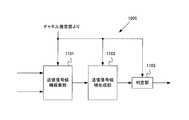
図11は、信号検出部1005の概略ブロック図である。信号検出部1005は、送信信号候補探索部1101、送信信号候補生成部1102、判定部1103を備える。送信信号候補探索部1101、送信信号候補生成部1102は第1の実施形態と同様であるので、説明は省略する。判定部1103は、送信信号候補を用いて、次式のように軟判定した場合の最尤系列であるビット対数尤度比を求める。

ただし、λk,nは第k送信アンテナから送信された変調シンボルの第nビットの対数尤度比である。またsbはb=[b1,1,…,bk,n,…,bNT,N]で定める送信信号候補を表す。b+はbのうちbk,n=1となる集合を表しており、b+=[b1,1,…,bk,n=1,…,bNT,N]である。b-はbのうちbk,n=0となる集合を表しており、b-=[b1,1,…,bk,n=0,…,bNT,N]である。従って、λk,nはb+を用いて生成される最小メトリックとb-を用いて生成される最小メトリックの差で求められる。
このように本実施形態では、誤り訂正符号化を行ったため、受信性能を向上させることができる。
なお、上記第5の実施形態では、符号化ビットを直列並列変換してデータストリームとしていたが、本発明はこれに限らず、ストリーム毎に符号化して符号化ビットを求めても良い。
(第6の実施形態)
図12は、本実施形態における受信装置の構成を示すブロック図である。
受信装置は、無線受信部1201-1~1201-NR、GI除去部1202-1~1202-NR、FFT(フーリエ変換:Fourier Transform)部1203-1~1203-NR、チャネル推定部1204、信号検出部1205、復号部1206を備える。
図12は、本実施形態における受信装置の構成を示すブロック図である。
受信装置は、無線受信部1201-1~1201-NR、GI除去部1202-1~1202-NR、FFT(フーリエ変換:Fourier Transform)部1203-1~1203-NR、チャネル推定部1204、信号検出部1205、復号部1206を備える。
本実施形態の受信装置と第5の実施形態の受信装置では、信号検出部1205及び復号部1206の動作のみ異なるので、その他のブロックの説明は省略する。信号検出部1205は復号部1206から得られる復号後のビット対数尤度比を利用して、さらに精度よくビット対数尤度比を求める。復号部1206は、誤り訂正復号の結果、誤りが検出され、かつ、規定回数の復号が行われていなければ、ビット対数尤度比を信号検出部1205に出力する。誤りが検出されない、もしくは、規定回数の復号が行われた場合は、復号の結果得られる送信ビットを出力する。なお、誤りの検出にはCRC(巡回冗長検査:Cyclic Redundancy Check)を用いることができる。
図13は、信号検出部1205の概略ブロック図である。
信号検出部1205は、送信信号候補探索部1301、送信信号候補生成部1302、判定部1303を備える。送信信号候補探索部1301は、上述の実施形態で説明したのと同様に送信信号候補を探索する。送信信号候補生成部1302は、図4の構成と同じで、空間相関の影響を抑圧して送信信号候補を生成する。判定部1303は、復号部1206から得られるビット対数尤度比を用いて、次のようにMIMO検出後のビット対数尤度比を求める。
信号検出部1205は、送信信号候補探索部1301、送信信号候補生成部1302、判定部1303を備える。送信信号候補探索部1301は、上述の実施形態で説明したのと同様に送信信号候補を探索する。送信信号候補生成部1302は、図4の構成と同じで、空間相関の影響を抑圧して送信信号候補を生成する。判定部1303は、復号部1206から得られるビット対数尤度比を用いて、次のようにMIMO検出後のビット対数尤度比を求める。

なお、p(bk,n)は第k送信アンテナから送信された変調シンボルの第nビットを表すbk,nの生起確率を表す。p(bk,n)は復号部1206から得られるビット対数尤度比から求めることができる。なお、送信信号候補探索部1301は、ビット対数尤度比から変調シンボルの期待値を求め、それを起点として送信信号の探索を行っても良い。なお、ビット対数尤度比を用いて送信信号の探索を行う場合、図示はしていないが、送信信号候補探索部1301にビット対数尤度比を入力する。また、判定部1303でのメトリック計算の結果、メトリックが大きい候補は、次の繰り返し処理における送信信号候補から削除してもよい。なお、既定の復号回数を1に設定した場合は、第5の実施形態と同様になる。
図14は、本実施形態の受信処理のフローチャートである。
ステップs1401では、送信信号候補探索部1301がMMSEの検出結果を起点とし、雑音強調を考慮して送信信号候補を探索し、結果を送信信号候補生成部1302に送る。ステップs1402では、送信信号候補生成部1302の第1のシフト・スケーリング部401が、量子化できるように変調方式に基づいてシフト及びスケーリングを行う。ステップs1403では、基底変換部402が基底変換行列によりチャネル行列の基底変換を行う。ステップs1404では、量子化部403が、整数値に近似するような量子化を行う。ステップs1405では、基底逆変換部404がステップs1403で行われた基底変換の逆変換を行う。ステップs1406では、第2のシフト・スケーリング部405が、ステップs1402の逆処理を行って送信信号候補を求める。ステップs1407では、判定部1303が送信信号候補と復号結果のビット対数尤度比を用いて、軟判定の最尤検出を行う。ステップs1408では、復号部1206が軟判定の最尤検出の結果得られるビット対数尤度比に対して誤り訂正復号を行なう。ステップs1409では、復号部1206が、誤りが未検出か、もしくは、規定回数の復号処理を行ったかを判断し、誤りが検出され、かつ、規定回数の復号処理が行われていない場合は、ステップs1407に移る。誤りが未検出、もしくは、規定回数の処理を行った場合、復号により得られた送信ビットを出力して受信処理を終了する。
ステップs1401では、送信信号候補探索部1301がMMSEの検出結果を起点とし、雑音強調を考慮して送信信号候補を探索し、結果を送信信号候補生成部1302に送る。ステップs1402では、送信信号候補生成部1302の第1のシフト・スケーリング部401が、量子化できるように変調方式に基づいてシフト及びスケーリングを行う。ステップs1403では、基底変換部402が基底変換行列によりチャネル行列の基底変換を行う。ステップs1404では、量子化部403が、整数値に近似するような量子化を行う。ステップs1405では、基底逆変換部404がステップs1403で行われた基底変換の逆変換を行う。ステップs1406では、第2のシフト・スケーリング部405が、ステップs1402の逆処理を行って送信信号候補を求める。ステップs1407では、判定部1303が送信信号候補と復号結果のビット対数尤度比を用いて、軟判定の最尤検出を行う。ステップs1408では、復号部1206が軟判定の最尤検出の結果得られるビット対数尤度比に対して誤り訂正復号を行なう。ステップs1409では、復号部1206が、誤りが未検出か、もしくは、規定回数の復号処理を行ったかを判断し、誤りが検出され、かつ、規定回数の復号処理が行われていない場合は、ステップs1407に移る。誤りが未検出、もしくは、規定回数の処理を行った場合、復号により得られた送信ビットを出力して受信処理を終了する。
このように復号結果のビット対数尤度比を用いて軟判定の最尤検出を行なうようにした。このため、MIMO検出の精度をさらに上げることができる。
なお、本発明に関わる受信装置で動作するプログラムは、本発明に関わる上記実施形態の機能を実現するように、CPU等を制御するプログラム(コンピュータを機能させるプログラム)である。そして、これら装置で取り扱われる情報は、その処理時に一時的にRAMに蓄積され、その後、各種ROMやHDDに格納され、必要に応じてCPUによって読み出し、修正・書き込みが行なわれる。プログラムを格納する記録媒体としては、半導体媒体(例えば、ROM、不揮発性メモリカード等)、光記録媒体(例えば、DVD、MO、MD、CD、BD等)、磁気記録媒体(例えば、磁気テープ、フレキシブルディスク等)等のいずれであってもよい。また、ロードしたプログラムを実行することにより、上述した実施形態の機能が実現されるだけでなく、そのプログラムの指示に基づき、オペレーティングシステムあるいは他のアプリケーションプログラム等と共同して処理することにより、本発明の機能が実現される場合もある。
また市場に流通させる場合には、可搬型の記録媒体にプログラムを格納して流通させたり、インターネット等のネットワークを介して接続されたサーバコンピュータに転送したりすることができる。この場合、サーバコンピュータの記憶装置も本発明に含まれる。また、上述した実施形態における移動局装置および基地局装置の一部、または全部を典型的な集積回路であるLSIとして実現してもよい。受信装置の各機能ブロックは個別にチップ化してもよいし、一部、または全部を集積してチップ化してもよい。各機能ブロックを集積回路化した場合に、それらを制御する集積回路制御部が付加される。
また、集積回路化の手法はLSIに限らず専用回路、または汎用プロセッサで実現しても良い。また、半導体技術の進歩によりLSIに代替する集積回路化の技術が出現した場合、当該技術による集積回路を用いることも可能である。
以上、この発明の実施形態を、図面を参照して詳述してきたが、具体的な構成はこの実施形態に限られるものではなく、この発明の要旨を逸脱しない範囲の設計等も特許請求の範囲に含まれる。
201 無線受信部
202 チャネル推定部
203,203a,203b 信号検出部
301 送信信号候補探索部
302 送信信号候補生成部
303 判定部
401 第1のシフト・スケーリング部
402 基底変換部
403 量子化部
404 基底逆変換部
405 第2のシフト・スケーリング部
701 送信信号候補探索部
702 候補選択部
703 送信信号候補生成部
704 判定部
1001 無線受信部
1002 GI除去部
1003 FFT部
1004 チャネル推定部
1005 信号検出部
1006 復号部
1101 送信信号候補探索部
1102 送信信号候補生成部
1103 判定部
1201 無線受信部
1202 GI除去部
1203 FFT部
1204 チャネル推定部
1205 信号検出部
1206 復号部
1301 送信信号候補探索部
1302 送信信号候補生成部
1303 判定部
2001 基底変換部
2002 第1のシフト・スケーリング部
2003 量子化部
2004 第2のシフト・スケーリング部
2005 基底逆変換部
2101 送信信号候補探索部
2102 送信信号候補生成部
2103 判定部
202 チャネル推定部
203,203a,203b 信号検出部
301 送信信号候補探索部
302 送信信号候補生成部
303 判定部
401 第1のシフト・スケーリング部
402 基底変換部
403 量子化部
404 基底逆変換部
405 第2のシフト・スケーリング部
701 送信信号候補探索部
702 候補選択部
703 送信信号候補生成部
704 判定部
1001 無線受信部
1002 GI除去部
1003 FFT部
1004 チャネル推定部
1005 信号検出部
1006 復号部
1101 送信信号候補探索部
1102 送信信号候補生成部
1103 判定部
1201 無線受信部
1202 GI除去部
1203 FFT部
1204 チャネル推定部
1205 信号検出部
1206 復号部
1301 送信信号候補探索部
1302 送信信号候補生成部
1303 判定部
2001 基底変換部
2002 第1のシフト・スケーリング部
2003 量子化部
2004 第2のシフト・スケーリング部
2005 基底逆変換部
2101 送信信号候補探索部
2102 送信信号候補生成部
2103 判定部
Claims (14)
- MIMO伝送によって通信を行なう受信装置であって、
雑音強調を考慮して送信信号候補の探索を行う送信信号候補探索部と、
前記探索した信号に対して、チャネルの空間相関の影響を抑圧して送信信号候補を生成する送信信号候補生成部と、
生成された前記送信信号候補を用いて最尤系列を求める判定部と、
を備えることを特徴とする受信装置。 - 前記送信信号候補生成部は、
変調方式に基づいてシフト及びスケーリングを行う第1のシフト・スケーリング部と、
基底変換行列を乗算して基底変換を行う基底変換部と、
整数値に丸める量子化部と、
前記基底変換部の逆操作を行う基底逆変換部と、
前記第1のシフト・スケーリング部の逆操作を行って前記送信信号候補を生成する第2のシフト・スケーリング部と、
を備えることを特徴とする請求項1に記載の受信装置。 - 前記送信信号候補生成部は、
基底変換行列を乗算して基底変換を行う基底変換部と、
変調方式に基づいてシフト及びスケーリングを行う第1のシフト・スケーリング部と、
整数値に丸める量子化部と、
前記第1のシフト・スケーリング部の逆操作を行う第2のシフト・スケーリング部と、
前記基底変換部の逆操作を行って前記送信信号候補を生成する基底逆変換部と、
を備えることを特徴とする請求項1に記載の受信装置。 - 前記送信信号候補生成部は、
拡張したチャネル行列及び受信信号を用いて前記送信信号候補を生成することを特徴とする請求項2または3に記載の受信装置。 - 前記送信信号候補探索部は、
雑音強調及びIQ平面で表現される任意の位置を考慮して送信信号候補の探索を行うことを特徴とする請求項1に記載の受信装置。 - 前記送信信号候補探索部は、
雑音強調及び変調方式を考慮して送信信号候補の探索を行うことを特徴とする請求項1に記載の受信装置。 - 前記送信信号候補探索部は、
線形検出結果のうち、一部の信号に対しては対応する送信信号候補の探索を行い、残りの信号は硬判定して出力することを特徴とする請求項1に記載に受信装置。 - 前記送信信号候補生成部は、
前記一部の信号に対応するチャネルを用いて送信信号候補を生成することを特徴とする請求項7に記載の受信装置。 - 前記探索した信号に対して、チャネルの空間相関に基づいて空間相関の影響を抑圧するか否かの選択を行なう候補選択部をさらに備えることを特徴とする請求項1に記載の受信装置。
- 前記候補選択部は、
空間相関の影響を抑圧しない信号を量子化して送信信号候補を生成し、
前記判定部は、前記送信信号候補生成部が生成した送信信号候補、及び、前記候補選択部が生成した送信信号候補を用いて最尤系列を求めることを特徴とする請求項9に記載の受信装置。 - 誤り訂正復号を行なう復号部をさらに備え、
前記判定部は、前記最尤系列のビット対数尤度比を求め、
前記復号部は、前記最尤系列のビット対数尤度比に対して誤り訂正復号を行なうことを特徴とする請求項1に記載の受信装置。 - 前記判定部は、前記送信信号候補及び前記復号後のビット対数尤度比から前記最尤系列のビット対数尤度比を求めることを特徴とする請求項11に記載の受信装置。
- MIMO伝送によって通信を行なう受信装置における受信方法であって、
雑音強調を考慮して送信信号候補の探索を行なう送信信号候補探索過程と、
前記探索した信号に対して、チャネルの空間相関の影響を抑圧して送信信号候補を生成する送信信号候補生成過程と、
生成された前記送信信号候補から最尤系列を求める判定過程と、
を有することを特徴とする受信方法。 - コンピュータに、請求項13に記載の受信方法の各過程を実行させるための受信プログラム。
Priority Applications (1)
| Application Number | Priority Date | Filing Date | Title |
|---|---|---|---|
| US14/237,601 US9008211B2 (en) | 2011-08-10 | 2012-08-06 | Receiving device, receiving method, and receiving program |
Applications Claiming Priority (2)
| Application Number | Priority Date | Filing Date | Title |
|---|---|---|---|
| JP2011-174700 | 2011-08-10 | ||
| JP2011174700A JP5854694B2 (ja) | 2011-08-10 | 2011-08-10 | 受信装置、受信方法、及び受信プログラム |
Publications (1)
| Publication Number | Publication Date |
|---|---|
| WO2013021973A1 true WO2013021973A1 (ja) | 2013-02-14 |
Family
ID=47668480
Family Applications (1)
| Application Number | Title | Priority Date | Filing Date |
|---|---|---|---|
| PCT/JP2012/070010 Ceased WO2013021973A1 (ja) | 2011-08-10 | 2012-08-06 | 受信装置、受信方法、及び受信プログラム |
Country Status (3)
| Country | Link |
|---|---|
| US (1) | US9008211B2 (ja) |
| JP (1) | JP5854694B2 (ja) |
| WO (1) | WO2013021973A1 (ja) |
Cited By (1)
| Publication number | Priority date | Publication date | Assignee | Title |
|---|---|---|---|---|
| CN103490807A (zh) * | 2013-09-11 | 2014-01-01 | 华南理工大学 | 一种基于fsd-mmse的mimo系统无线接收检测方法 |
Families Citing this family (10)
| Publication number | Priority date | Publication date | Assignee | Title |
|---|---|---|---|---|
| EP2966821A1 (en) * | 2014-07-11 | 2016-01-13 | Mitsubishi Electric R&D Centre Europe B.V. | Method for configuring a receiver receiving symbol vectors via a linear fading transmission channel |
| US10243696B2 (en) * | 2014-11-25 | 2019-03-26 | Syracuse University | Diversity combining of non-coherently modulated LDPC codes in wireless communications |
| JP2016163078A (ja) * | 2015-02-26 | 2016-09-05 | 富士通株式会社 | 復調装置および復調方法 |
| JP6587745B2 (ja) * | 2016-05-26 | 2019-10-09 | 株式会社日立国際電気 | 無線通信装置及び無線通信方法 |
| CN107592676B (zh) * | 2016-07-08 | 2023-05-02 | 中兴通讯股份有限公司 | 一种数据生成方法及装置、发射机、终端 |
| US10387534B2 (en) * | 2016-11-28 | 2019-08-20 | Yissum Research Development Company Of The Hebrew University Of Jerusalem Ltd. | Fast matrix multiplication and linear algebra by alternative basis |
| WO2019051093A1 (en) * | 2017-09-06 | 2019-03-14 | Cohere Technologies | REDUCTION OF TRELLIS IN TIME, FREQUENCY AND ORTHOGONAL SPATIAL MODULATION |
| CN113614079A (zh) * | 2019-03-15 | 2021-11-05 | 日产化学株式会社 | 杂环酰胺化合物的结晶及其制造方法 |
| JP7136028B2 (ja) * | 2019-07-18 | 2022-09-13 | 日本電信電話株式会社 | 無線通信システム、中継装置及び受信装置 |
| CN116264704B (zh) * | 2023-05-08 | 2023-09-08 | 深圳大学 | 基于信道感知和强化学习的低功耗广域网通感融合方法 |
Citations (1)
| Publication number | Priority date | Publication date | Assignee | Title |
|---|---|---|---|---|
| JP2008048219A (ja) * | 2006-08-17 | 2008-02-28 | Samsung Electronics Co Ltd | 通信システム、通信装置、尤度計算方法、及びプログラム |
Family Cites Families (2)
| Publication number | Priority date | Publication date | Assignee | Title |
|---|---|---|---|---|
| CN1829138B (zh) * | 2006-04-07 | 2010-04-07 | 清华大学 | 自适应多输入多输出发送接收系统及其方法 |
| EP2502392B1 (en) * | 2009-11-16 | 2013-09-25 | Fujitsu Limited | Mimo wireless communication systems |
-
2011
- 2011-08-10 JP JP2011174700A patent/JP5854694B2/ja not_active Expired - Fee Related
-
2012
- 2012-08-06 WO PCT/JP2012/070010 patent/WO2013021973A1/ja not_active Ceased
- 2012-08-06 US US14/237,601 patent/US9008211B2/en not_active Expired - Fee Related
Patent Citations (1)
| Publication number | Priority date | Publication date | Assignee | Title |
|---|---|---|---|---|
| JP2008048219A (ja) * | 2006-08-17 | 2008-02-28 | Samsung Electronics Co Ltd | 通信システム、通信装置、尤度計算方法、及びプログラム |
Non-Patent Citations (4)
| Title |
|---|
| DIRK WUBBEN ET AL.: "`Near-Maximum-Likelihood Detection of MIMO Systems using MMSE-Based Lattice-Reduction", COMMUNICATIONS, 2004 IEEE INTERNATIONAL CONFERENCE ON, 20 June 2004 (2004-06-20), pages 798 - 802 * |
| HUAN YAO ET AL.: "`Lattice-Reduction-Aided Detectors for MIMO Communication Systems", GLOBAL TELECOMMUNICATIONS CONFERENCE, 2002. GLOBECOM '02., 17 November 2002 (2002-11-17), pages 424 - 428 * |
| KAZUHIKO FUKAWA ET AL.: "Suboptimal Signal Detection for MIMO Communications", IEICE TECHNICAL REPORT, RCS2011-53, THE INSTITUTE OF ELECTRONICS, INFORMATION AND COMMUNICATION ENGINEERS, 16 June 2011 (2011-06-16), pages 105 - 110 * |
| LIMING ZHENG ET AL.: "Near-Optimal Signal Detection Based on the MMSE Detection Using Multi-Dimensional Search for Correlated MIMO Channels", IEICE TRANSACTIONS ON COMMUNICATIONS, THE INSTITUTE OF ELECTRONICS, INFORMATION AND COMMUNICATION ENGINEERS, 1 August 2011 (2011-08-01), pages 2346 - 2356 * |
Cited By (1)
| Publication number | Priority date | Publication date | Assignee | Title |
|---|---|---|---|---|
| CN103490807A (zh) * | 2013-09-11 | 2014-01-01 | 华南理工大学 | 一种基于fsd-mmse的mimo系统无线接收检测方法 |
Also Published As
| Publication number | Publication date |
|---|---|
| US20140192936A1 (en) | 2014-07-10 |
| US9008211B2 (en) | 2015-04-14 |
| JP2013038676A (ja) | 2013-02-21 |
| JP5854694B2 (ja) | 2016-02-09 |
Similar Documents
| Publication | Publication Date | Title |
|---|---|---|
| JP5854694B2 (ja) | 受信装置、受信方法、及び受信プログラム | |
| CN106067869B (zh) | 用于对高阶qam符号进行软检测的方法和设备 | |
| US8488721B2 (en) | Adaptive QRD-M algorithm based signal detecting method by using constellation set grouping in spatial multiplexing multiple-input multiple-output system | |
| RU2303330C1 (ru) | Способ приема сигнала в системе связи с несколькими каналами передачи и приема | |
| JP6180333B2 (ja) | 無線周波数受信機において信号を復号化する方法 | |
| CN116708094B (zh) | 多输入多输出系统的检测方法和装置、设备、介质 | |
| JP5276711B2 (ja) | Mimo受信方法 | |
| WO2016121625A1 (en) | Method for decoding block of data received over communication channel and receiver | |
| CN109167648B (zh) | 候选星座点集合生成方法及mimo空间复用检测方法 | |
| US9191155B2 (en) | Reception device, reception method, and program | |
| JP2016171436A (ja) | 通信装置、復調方法及びプログラム | |
| WO2015156058A1 (ja) | 受信装置 | |
| KR101731723B1 (ko) | 다중 안테나 시스템에서 연판정 검출 방법 및 장치 | |
| RU2444846C1 (ru) | Способ детектирования сигнала в системах связи с mimo каналом | |
| US8457238B2 (en) | Method of soft decision decoding and apparatus for soft decision decoding | |
| JP5397257B2 (ja) | 受信装置、及び受信方法 | |
| US8081577B2 (en) | Method of calculating soft value and method of detecting transmission signal | |
| US10419084B2 (en) | Wireless communication device and wireless communication method | |
| JP4611271B2 (ja) | 受信装置 | |
| JP5367474B2 (ja) | 受信装置及び受信方法 | |
| KR100747595B1 (ko) | 다수의 송수신 안테나를 구비한 통신시스템의 연판정 심볼검출 장치 및 그 방법 | |
| KR100888649B1 (ko) | Mimo 시스템에서 송신 신호 검출을 위한 복호 장치 및방법 | |
| CN109039539B (zh) | 候选星座点集合生成方法及mimo空间复用检测方法 | |
| JP5578674B2 (ja) | 無線通信機および無線通信方法 | |
| JP2014068094A (ja) | 受信装置、受信方法およびプログラム |
Legal Events
| Date | Code | Title | Description |
|---|---|---|---|
| 121 | Ep: the epo has been informed by wipo that ep was designated in this application |
Ref document number: 12821463 Country of ref document: EP Kind code of ref document: A1 |
|
| WWE | Wipo information: entry into national phase |
Ref document number: 14237601 Country of ref document: US |
|
| NENP | Non-entry into the national phase |
Ref country code: DE |
|
| 122 | Ep: pct application non-entry in european phase |
Ref document number: 12821463 Country of ref document: EP Kind code of ref document: A1 |