WO2013018514A1 - Outil électrique de type rotatif oscillant - Google Patents
Outil électrique de type rotatif oscillant Download PDFInfo
- Publication number
- WO2013018514A1 WO2013018514A1 PCT/JP2012/067565 JP2012067565W WO2013018514A1 WO 2013018514 A1 WO2013018514 A1 WO 2013018514A1 JP 2012067565 W JP2012067565 W JP 2012067565W WO 2013018514 A1 WO2013018514 A1 WO 2013018514A1
- Authority
- WO
- WIPO (PCT)
- Prior art keywords
- housing
- tool
- reciprocating rotary
- electric tool
- rotary electric
- Prior art date
Links
Images

Classifications
-
- B—PERFORMING OPERATIONS; TRANSPORTING
- B27—WORKING OR PRESERVING WOOD OR SIMILAR MATERIAL; NAILING OR STAPLING MACHINES IN GENERAL
- B27B—SAWS FOR WOOD OR SIMILAR MATERIAL; COMPONENTS OR ACCESSORIES THEREFOR
- B27B19/00—Other reciprocating saws with power drive; Fret-saws
- B27B19/006—Other reciprocating saws with power drive; Fret-saws with oscillating saw blades; Hand saws with oscillating saw blades
-
- B—PERFORMING OPERATIONS; TRANSPORTING
- B24—GRINDING; POLISHING
- B24B—MACHINES, DEVICES, OR PROCESSES FOR GRINDING OR POLISHING; DRESSING OR CONDITIONING OF ABRADING SURFACES; FEEDING OF GRINDING, POLISHING, OR LAPPING AGENTS
- B24B23/00—Portable grinding machines, e.g. hand-guided; Accessories therefor
- B24B23/04—Portable grinding machines, e.g. hand-guided; Accessories therefor with oscillating grinding tools; Accessories therefor
Definitions
- the present invention relates to a reciprocating rotary electric tool in which an output shaft that reciprocates left and right by driving a motor is protruded downward from a front end portion of a housing that houses a motor, and a tip tool is connected to the tip of the output shaft.
- a motor is housed in a housing extending in the front-rear direction, and an output shaft coupled with a tip tool is projected downward in a direction orthogonal to the front-rear axis of the housing from the front end portion of the housing.
- a reciprocating rotary power tool is disclosed.
- the rotation of the motor is transmitted to the output shaft through the swing mechanism, and the swing mechanism can switch the rotational motion of the motor to a motion in which the output shaft reciprocates left and right. Has been made.
- the present invention has been proposed in view of such circumstances, and an object thereof is to provide a reciprocating rotary electric tool with improved workability.
- the invention of claim 1 is a reciprocating rotary electric tool, A housing extending in the front-rear direction; A motor housed in the housing; An output shaft that protrudes downward from the front end of the housing and reciprocates left and right by driving the motor; A tip tool connected to the tip of the output shaft, The axis of the output shaft is inclined forward by a predetermined angle from a direction orthogonal to the longitudinal axis of the housing.
- the invention of claim 2 is characterized in that, in claim 1, a battery for supplying power to the motor is detachable at a rear end portion of the housing.
- the housing when surface polishing is performed on the workpiece with a tip tool, the housing is located above the position parallel to the polishing surface of the workpiece. It becomes possible to maintain an inclined state. Therefore, the distance between the polishing surface and the housing becomes wider than when the housing is kept parallel to the polishing surface. Therefore, the housing can be prevented from hitting a member protruding from the workpiece in the vicinity of the polishing surface, for example. Moreover, also when performing planar grinding
- the battery when performing the planar polishing, is mounted on the rear end surface inclined upward from the position parallel to the polishing surface, so that the battery is polished or polished. Can be prevented from coming into contact with a member protruding from the workpiece. Therefore, the battery does not hinder polishing work or the like.
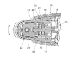
- FIG. 3 is a cross-sectional view taken along line AA in FIG. 2.
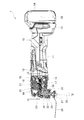
- a reciprocating rotary power tool 1 shown in FIGS. 1 and 2 includes a main body housing 10 having a circular cross section and extending in the front-rear direction of the reciprocating rotary power tool 1 (left-right direction in FIGS. 1 and 2).
- a grip 11 for a user to grip is formed on the outer periphery of the main body housing 10, and a motor (not shown) is accommodated in the main body housing 10.
- the main body housing 10 is provided with a switch 12 capable of switching the motor between an on state and an off state.
- a battery mounting portion 13 is provided at the rear end portion of the main body housing 10.
- a battery pack 14 that supplies power to the motor when the switch 12 is on is detachably mounted on the battery mounting portion 13.
- the battery pack 14 is an example of the battery of the present invention.
- a shaft member 17 is connected to the front of the rotating shaft 15 of the motor in the main body housing 10 via a coupling member 16.
- the shaft member 17 is supported in a rotatable state in the main body housing 10 via bearings 18 and 19.
- An eccentric shaft portion 20 is formed at a substantially central portion in the axial direction of the shaft member 17.
- a bearing 21 whose outer ring has an arc shape is assembled to the eccentric shaft portion 20 in an exterior state.
- the spindle 22 is supported in the main body housing 10 via bearings 23 and 24 at the front end of the main body housing 10.
- the axis 25 of the spindle 22 is inclined to the front side of the main body housing 10 by a predetermined angle ⁇ (here, 5 degrees) from the direction orthogonal to the longitudinal axis 26 of the main body housing 10.
- the tip of the spindle 22 protrudes downward from the main body housing 10.
- Various types of tip tools having different shapes and applications such as cutting tools and polishing tools can be fixed to the tip of the spindle 22 with bolts 27, respectively.
- 1 and 2 show an example in which a cutting tool 28 having a fan shape in plan view is fixed to the spindle 22.
- the main body housing 10 is an example of the housing of the present invention
- the spindle 22 is an example of the output shaft of the present invention.
- the cutting tool 28 is an example of the tip tool of the present invention.
- a link member 30 is supported between the shaft member 17 and the spindle 22 in the main body housing 10.
- the link member 30 includes a pair of engaging portions 32 and 32 and an arm portion 33.
- a pair of engaging parts 32 and 32 are arrange
- a bearing 21 is disposed in a space between the engaging portions 32 and 32.
- the arm portion 33 protrudes from the main body of the link member 30 toward the spindle 22, and a spindle positioning hole 34 is formed in the arm portion 33.
- the spindle 22 is press-fitted into the spindle positioning hole 34.
- the reciprocating rotary electric tool 1 As an example, the operation of cutting a pillar material standing on the floor will be described.
- the user drives the motor by turning on the switch 12 while grasping the grip portion 11.
- the bearing 21 assembled to the eccentric shaft portion 20 rotates eccentrically about the shaft member 17.
- the link member 30 is reciprocatingly rotated and electrically driven as indicated by arrows in FIG. 3 by repeating the movement in which the bearing 21 abuts only on the engaging portions 32 and 32 of the link member 30 in the left-right direction.
- the tool 1 reciprocates left and right when viewed from the front.
- the spindle 22 and the cutting tool 28 reciprocate left and right around the axis 25.
- the pillar material is cut by pressing the cutting tool 28 that reciprocates while keeping the spindle 22 in a state orthogonal to the floor surface against the pillar material.
- the axis 26 of the main body housing 10 is inclined upward from the direction orthogonal to the axis 25 of the spindle 22.
- the main body housing 10 will be in the state inclined to the upper side rather than the state parallel to a floor surface. Therefore, the space between the floor surface and the main body housing 10 becomes wider than when the main body housing 10 is kept parallel to the floor surface. Therefore, even if a member that rises slightly from the floor surface is provided in the vicinity of the column member, the main body housing 10 can be prevented from hitting this member.
- the battery mounting portion 13 to which the battery pack 14 is mounted protrudes from the main body housing 10 to the floor surface side, so that the battery pack 14 also protrudes from the main body housing 10 to the floor surface side.
- the battery pack 14 is mounted on a battery mounting portion 13 provided at the rear end portion of the main body housing 10 inclined upward. Therefore, the battery mounting part 13 and the battery pack 14 are prevented from coming into contact with the floor surface, and the battery mounting part 13 and the battery pack 14 are prevented from coming into contact with a member slightly rising from the floor surface in the vicinity of the pillar material. it can.
- the battery pack 14 is mounted on the battery mounting portion 13 provided at the rear end portion of the main body housing 10 inclined upward, so that the battery pack 14 is in the vicinity of the floor surface or the column material. With this, it is possible to prevent contact with a member that rises slightly from the floor. Therefore, the battery pack 14 does not interfere with the cutting of the pillar material.
- the present invention is not limited to the embodiment described above, and can be implemented by appropriately changing a part of the configuration without departing from the spirit of the invention.
- the axis 25 of the spindle 22 may be inclined toward the front side of the main body housing 10 by an appropriate angle of less than 5 degrees or more than 6 degrees from the direction orthogonal to the axis 26 of the main body housing 10.
- the column material is cut with the reciprocating rotary electric tool. You may make it perform planar grinding
- the main body housing is inclined upward from a state parallel to the floor surface, so that the main body housing can be prevented from hitting the floor surface.
- this invention to a rechargeable reciprocating rotary electric tool was shown in embodiment mentioned above, you may apply this invention to an AC drive type reciprocating rotary electric tool. .
Landscapes
- Engineering & Computer Science (AREA)
- Mechanical Engineering (AREA)
- Life Sciences & Earth Sciences (AREA)
- Wood Science & Technology (AREA)
- Forests & Forestry (AREA)
- Portable Power Tools In General (AREA)
- Finish Polishing, Edge Sharpening, And Grinding By Specific Grinding Devices (AREA)
- Sawing (AREA)
Abstract
L'objet de la présente invention est de proposer un outil électrique de type rotatif oscillant dans lequel le rendement de travail est amélioré. À cette fin, la présente invention concerne un outil électrique de type rotatif oscillant (1) dans lequel un arbre de sortie (22) mis en rotation vers la droite et la gauche de manière oscillante par l'entraînement d'un moteur fait saillie vers le bas au niveau de la partie d'extrémité avant d'un logement (10) qui s'étend dans le sens avant-arrière et loge le moteur, et un outil d'extrémité distale (28) est raccordé à l'extrémité distale de l'arbre de sortie (22), l'axe (25) de l'arbre de sortie (22) étant incliné vers l'avant à un angle prédéterminé θ depuis la direction perpendiculaire à l'axe dirigé vers l'avant-arrière (26) du logement (10). Une batterie (14) permettant de fournir une alimentation électrique au moteur est également fixée de manière amovible à la partie d'extrémité arrière du logement (10).
Applications Claiming Priority (2)
| Application Number | Priority Date | Filing Date | Title |
|---|---|---|---|
| JP2011169525A JP2013031906A (ja) | 2011-08-02 | 2011-08-02 | 往復回転式電動工具 |
| JP2011-169525 | 2011-08-02 |
Publications (1)
| Publication Number | Publication Date |
|---|---|
| WO2013018514A1 true WO2013018514A1 (fr) | 2013-02-07 |
Family
ID=47629045
Family Applications (1)
| Application Number | Title | Priority Date | Filing Date |
|---|---|---|---|
| PCT/JP2012/067565 WO2013018514A1 (fr) | 2011-08-02 | 2012-07-10 | Outil électrique de type rotatif oscillant |
Country Status (2)
| Country | Link |
|---|---|
| JP (1) | JP2013031906A (fr) |
| WO (1) | WO2013018514A1 (fr) |
Cited By (3)
| Publication number | Priority date | Publication date | Assignee | Title |
|---|---|---|---|---|
| JP2015104770A (ja) * | 2013-11-29 | 2015-06-08 | 日立工機株式会社 | 電動工具 |
| WO2017142092A1 (fr) * | 2016-02-19 | 2017-08-24 | 株式会社マキタ | Outil de travail |
| US9956676B2 (en) | 2013-01-09 | 2018-05-01 | Techtronic Power Tools Technology Limited | Tool with rotatable head |
Families Citing this family (1)
| Publication number | Priority date | Publication date | Assignee | Title |
|---|---|---|---|---|
| JP6252970B2 (ja) * | 2013-07-30 | 2017-12-27 | 日立工機株式会社 | 電動工具 |
Citations (6)
| Publication number | Priority date | Publication date | Assignee | Title |
|---|---|---|---|---|
| JPS6161761A (ja) * | 1984-08-29 | 1986-03-29 | Makita Denki Seisakusho:Kk | コ−ドレス研摩機 |
| DE3840974A1 (de) * | 1988-12-06 | 1990-06-07 | Fein C & E | Oszillationsantrieb |
| JPH0285543U (fr) * | 1988-12-19 | 1990-07-05 | ||
| JPH0537452U (ja) * | 1991-10-25 | 1993-05-21 | リヨービ株式会社 | 研磨装置の揺動駆動機構 |
| JP2000233355A (ja) * | 1999-02-10 | 2000-08-29 | Ryobi Ltd | サンダ |
| JP2002066897A (ja) * | 2000-08-25 | 2002-03-05 | Makita Corp | 携帯用電動工具 |
-
2011
- 2011-08-02 JP JP2011169525A patent/JP2013031906A/ja not_active Withdrawn
-
2012
- 2012-07-10 WO PCT/JP2012/067565 patent/WO2013018514A1/fr active Application Filing
Patent Citations (6)
| Publication number | Priority date | Publication date | Assignee | Title |
|---|---|---|---|---|
| JPS6161761A (ja) * | 1984-08-29 | 1986-03-29 | Makita Denki Seisakusho:Kk | コ−ドレス研摩機 |
| DE3840974A1 (de) * | 1988-12-06 | 1990-06-07 | Fein C & E | Oszillationsantrieb |
| JPH0285543U (fr) * | 1988-12-19 | 1990-07-05 | ||
| JPH0537452U (ja) * | 1991-10-25 | 1993-05-21 | リヨービ株式会社 | 研磨装置の揺動駆動機構 |
| JP2000233355A (ja) * | 1999-02-10 | 2000-08-29 | Ryobi Ltd | サンダ |
| JP2002066897A (ja) * | 2000-08-25 | 2002-03-05 | Makita Corp | 携帯用電動工具 |
Cited By (3)
| Publication number | Priority date | Publication date | Assignee | Title |
|---|---|---|---|---|
| US9956676B2 (en) | 2013-01-09 | 2018-05-01 | Techtronic Power Tools Technology Limited | Tool with rotatable head |
| JP2015104770A (ja) * | 2013-11-29 | 2015-06-08 | 日立工機株式会社 | 電動工具 |
| WO2017142092A1 (fr) * | 2016-02-19 | 2017-08-24 | 株式会社マキタ | Outil de travail |
Also Published As
| Publication number | Publication date |
|---|---|
| JP2013031906A (ja) | 2013-02-14 |
Similar Documents
| Publication | Publication Date | Title |
|---|---|---|
| JP6262605B2 (ja) | 作業工具 | |
| EP3632603B1 (fr) | Outil à mouvement alternatif | |
| JP6129668B2 (ja) | 電動工具 | |
| JP5589255B2 (ja) | 携帯用電動工具 | |
| JP6501414B2 (ja) | 打撃工具 | |
| WO2013046541A1 (fr) | Outil d'oscillation | |
| US10058926B2 (en) | Power tool | |
| WO2013018514A1 (fr) | Outil électrique de type rotatif oscillant | |
| JP6661328B2 (ja) | 電動工具 | |
| JP2011115912A (ja) | 往復運動工具 | |
| WO2013038789A1 (fr) | Outil électrique | |
| CN107206584B (zh) | 作业工具 | |
| JP5818085B2 (ja) | 往復動工具及び往復動工具に装着されるアタッチメント | |
| CN201821205U (zh) | 摆动动力工具 | |
| WO2014192455A1 (fr) | Outil de coupe à mouvement alternatif | |
| JP3897653B2 (ja) | 往復動式電動工具 | |
| EP3568265B1 (fr) | Outil oscillant à multiples angles d'oscillation | |
| JP6480975B2 (ja) | 電動工具 | |
| JP6252970B2 (ja) | 電動工具 | |
| CN102447344A (zh) | 摆动动力工具 | |
| JP2016087725A (ja) | 往復動工具 | |
| JP2007118181A (ja) | セーバソー | |
| CN215789650U (zh) | 电动工具 | |
| JP2008114343A (ja) | 電動工具 | |
| JP2017144541A (ja) | 作業工具 |
Legal Events
| Date | Code | Title | Description |
|---|---|---|---|
| 121 | Ep: the epo has been informed by wipo that ep was designated in this application |
Ref document number: 12819982 Country of ref document: EP Kind code of ref document: A1 |
|
| NENP | Non-entry into the national phase |
Ref country code: DE |
|
| 122 | Ep: pct application non-entry in european phase |
Ref document number: 12819982 Country of ref document: EP Kind code of ref document: A1 |