WO2013018154A1 - Douille, dispositif de lampe et appareil d'éclairage - Google Patents
Douille, dispositif de lampe et appareil d'éclairage Download PDFInfo
- Publication number
- WO2013018154A1 WO2013018154A1 PCT/JP2011/067404 JP2011067404W WO2013018154A1 WO 2013018154 A1 WO2013018154 A1 WO 2013018154A1 JP 2011067404 W JP2011067404 W JP 2011067404W WO 2013018154 A1 WO2013018154 A1 WO 2013018154A1
- Authority
- WO
- WIPO (PCT)
- Prior art keywords
- socket
- base
- mounting
- lamp device
- key
- Prior art date
Links
Images


Classifications
-
- F—MECHANICAL ENGINEERING; LIGHTING; HEATING; WEAPONS; BLASTING
- F21—LIGHTING
- F21V—FUNCTIONAL FEATURES OR DETAILS OF LIGHTING DEVICES OR SYSTEMS THEREOF; STRUCTURAL COMBINATIONS OF LIGHTING DEVICES WITH OTHER ARTICLES, NOT OTHERWISE PROVIDED FOR
- F21V23/00—Arrangement of electric circuit elements in or on lighting devices
- F21V23/06—Arrangement of electric circuit elements in or on lighting devices the elements being coupling devices, e.g. connectors
-
- F—MECHANICAL ENGINEERING; LIGHTING; HEATING; WEAPONS; BLASTING
- F21—LIGHTING
- F21V—FUNCTIONAL FEATURES OR DETAILS OF LIGHTING DEVICES OR SYSTEMS THEREOF; STRUCTURAL COMBINATIONS OF LIGHTING DEVICES WITH OTHER ARTICLES, NOT OTHERWISE PROVIDED FOR
- F21V17/00—Fastening of component parts of lighting devices, e.g. shades, globes, refractors, reflectors, filters, screens, grids or protective cages
- F21V17/005—Fastening of component parts of lighting devices, e.g. shades, globes, refractors, reflectors, filters, screens, grids or protective cages with keying means, i.e. for enabling the assembling of component parts in distinctive positions, e.g. for preventing wrong mounting
-
- F—MECHANICAL ENGINEERING; LIGHTING; HEATING; WEAPONS; BLASTING
- F21—LIGHTING
- F21V—FUNCTIONAL FEATURES OR DETAILS OF LIGHTING DEVICES OR SYSTEMS THEREOF; STRUCTURAL COMBINATIONS OF LIGHTING DEVICES WITH OTHER ARTICLES, NOT OTHERWISE PROVIDED FOR
- F21V17/00—Fastening of component parts of lighting devices, e.g. shades, globes, refractors, reflectors, filters, screens, grids or protective cages
- F21V17/10—Fastening of component parts of lighting devices, e.g. shades, globes, refractors, reflectors, filters, screens, grids or protective cages characterised by specific fastening means or way of fastening
- F21V17/14—Bayonet-type fastening
-
- F—MECHANICAL ENGINEERING; LIGHTING; HEATING; WEAPONS; BLASTING
- F21—LIGHTING
- F21K—NON-ELECTRIC LIGHT SOURCES USING LUMINESCENCE; LIGHT SOURCES USING ELECTROCHEMILUMINESCENCE; LIGHT SOURCES USING CHARGES OF COMBUSTIBLE MATERIAL; LIGHT SOURCES USING SEMICONDUCTOR DEVICES AS LIGHT-GENERATING ELEMENTS; LIGHT SOURCES NOT OTHERWISE PROVIDED FOR
- F21K9/00—Light sources using semiconductor devices as light-generating elements, e.g. using light-emitting diodes [LED] or lasers
- F21K9/20—Light sources comprising attachment means
-
- F—MECHANICAL ENGINEERING; LIGHTING; HEATING; WEAPONS; BLASTING
- F21—LIGHTING
- F21S—NON-PORTABLE LIGHTING DEVICES; SYSTEMS THEREOF; VEHICLE LIGHTING DEVICES SPECIALLY ADAPTED FOR VEHICLE EXTERIORS
- F21S8/00—Lighting devices intended for fixed installation
- F21S8/02—Lighting devices intended for fixed installation of recess-mounted type, e.g. downlighters
- F21S8/026—Lighting devices intended for fixed installation of recess-mounted type, e.g. downlighters intended to be recessed in a ceiling or like overhead structure, e.g. suspended ceiling
Definitions
- Embodiments of the present invention relate to a socket in which a lamp device is mounted, a lamp device to be mounted in the socket, and a lighting fixture using the socket and the lamp device.
- a lighting fixture that uses a combination of a flat lamp device using, for example, a GX-type base and a fixture device having a socket on which the base of the lamp device is detachably attached.
- a light source and a lighting circuit for lighting the light source are housed in a casing having a base.
- the light source is turned on by the lighting circuit of the lamp device by supplying power of a predetermined voltage from the socket to the lamp device.
- the lighting fixture for example, when preparing a plurality of types of lamp devices according to the difference in the voltage of the power supplied to the lamp device or the difference in the output of the light source, It will be used in combination with the instrument device. In this case, it is preferable to have a function of preventing erroneous mounting of the lamp device in the socket with a combination of incompatible types. However, if the function of preventing erroneous mounting is provided, the lamp device can be used even with a compatible type of combination. There is a possibility that the mounting property of mounting the to the socket is likely to deteriorate.
- the problem to be solved by the present invention is to provide a socket that has an erroneous mounting prevention function and that can improve the mounting performance of the lamp device, a lamp device mounted in the socket, and a lighting fixture using the socket and the lamp device. That is.
- the socket includes a base body, a cylindrical base protrusion protruding from the base body, a plurality of erroneous mounting prevention grooves provided at predetermined positions around a tip end of the base protrusion, and the base protrusion It is a socket for detachably mounting a lamp device provided with a base having an attachment key protruding from a predetermined position on the outer peripheral surface away from the tip surface of the base protrusion.
- the socket includes a socket body provided with a socket surface to which the base body is attached. A cylindrical insertion opening through which the cap projection is inserted opens on the socket surface.
- a plurality of erroneous mounting prevention keys protrude from a position away from the socket surface at a predetermined position on the inner peripheral surface of the insertion port.
- the distance from the socket surface to the position of the erroneous mounting prevention key is smaller than the distance from the tip surface of the cap projection to the mounting key.
- the erroneous mounting prevention groove of the base protrusion is inserted through the erroneous mounting prevention key, and the base protrusion is inserted to the predetermined insertion position in the insertion opening.
- a mounting groove is provided on the inner peripheral surface of the insertion opening. The mounting groove is inserted with a mounting key of a base projection that is inserted into a predetermined insertion position in the insertion port, and attaches the base to the socket body via the mounting key.
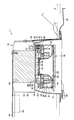
- FIG. 3 is a partial cross-sectional view of a state in which a tip end surface of a base projection of a base of a lamp device is in contact with a wrong mounting prevention key of a socket according to the first embodiment.
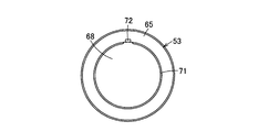
- It is a perspective view of a socket same as the above.
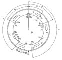
- It is a front view of a socket same as the above.
- It is a front view of a base same as the above.
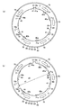
- the socket with the same base as above is shown, (a) is a front view of the misfit prevention groove of the base aligned with the misinstallation prevention key of the socket, and (b) is the misfit prevention groove of the base to prevent misinstallation of the socket.
- It is a front view of the state which has shifted
- 1 to 7 show a first embodiment.
- the luminaire 11 is an embedded luminaire such as a downlight, and is installed by being embedded in a circular embedding hole 13 provided in the ceiling plate 12.
- the luminaire 11 includes a flat lamp device 14 and a fixture device 15 on which the lamp device 14 is detachably mounted.
- the vertical relationship between the lamp device 14 and the fixture device 15 is referred to based on the installation state of the lighting fixture 11 on the ceiling plate 12.
- lamp devices 14 There are multiple types of lamp devices 14 depending on the corresponding voltage of the input power supply and the output of the light source. There are a plurality of types of fixture devices 15 corresponding to the types of lamp devices 14 depending on the difference in heat dissipation performance.
- the types of the corresponding voltage of the lamp device 14 for example, there are types for 100V, 200V, and voltage-free for any voltage of 100V and 200V.
- the lamp device 14 includes a flat and cylindrical casing 21.
- a light source 22, a reflector 23, and a lighting circuit 24 are housed in the housing 21, and a translucent cover 25 is attached to the lower surface of the housing 21.
- the housing 21 has a cylindrical case 27 and a disk-shaped base member 28 attached to the upper surface of the case 27.
- the upper part of the case 27 and the base member 28 constitute a base 29 having a predetermined standard size.
- the case 27 is made of an insulating synthetic resin, and has an end plate portion 31 on the upper surface, a cylindrical peripheral surface portion 32 projecting downward from the peripheral portion of the end plate portion 31, and an upper surface from the upper surface of the end plate portion 31. It has a cylindrical tube portion 33 that protrudes. The lower surface of the case 27 is opened.
- the base member 28 is formed in a disc shape with a metal material such as aluminum die casting.
- the diameter of the base member 28 is larger than the diameter of the cylindrical part 33 of the case 27, and the peripheral part of the base member 28 protrudes from the outer peripheral surface of the cylindrical part 33 of the case 27.
- a heat conductive sheet 34 is attached to the upper surface of the base member 28.
- the end plate portion 31 and the peripheral surface portion 32 of the case 27 are configured as a base body 35, and the cylindrical portion 33 and the base member 28 of the case 27 are configured as a cylindrical base protrusion 36 that protrudes from the base body 35. Yes. Further, the upper surface of the end plate portion 31 of the case 27 is configured as a base surface 37, and the upper surface of the base member 28 is configured as a tip surface 38 of the base projection 36.
- a plurality of lamp pins 39 project from the base surface 37 of the base body 35.
- there are five lamp pins 39 including two power supply input lamp pins 39, two dimming signal input lamp pins 39, and a ground connection lamp pin 39. If the lamp pin 39 for power supply input is provided, the lamp pin 39 for dimming signal input and ground connection may not be provided.
- a plurality of erroneous mounting prevention grooves 40 are formed in the periphery of the base member 28, and a plurality of mounting keys 41 are formed so as to be positioned between the adjacent erroneous mounting prevention grooves 40 in the circumferential direction. ing.
- attachment keys 41 there are three attachment keys 41, which are provided at equal intervals in the circumferential direction of the base member 28 every 120 °, and one of the three is a reference.
- the mounting key 41s As shown in FIG. 1, the mounting key 41 protrudes from the periphery of the base member 28 in the outer diameter direction from a position separated by a predetermined distance L1 from the upper surface of the base member 28, that is, the front end surface 38 toward the base body 35. ing.
- erroneous mounting prevention grooves 40 among the plurality of erroneous mounting prevention grooves 40, three are erroneous mounting prevention grooves 40a for voltage discrimination that prevent erroneous mounting when the corresponding voltage of the lamp device 14 is different.
- erroneous mounting prevention groove 40b for output discrimination corresponding to the difference in output of the lamp device 14.
- the three erroneous voltage-preventing grooves 40a for distinguishing voltages are formed at positions separated by predetermined angles y1, y2, and y3 in the circumferential direction of the base member 28 with respect to the reference mounting key 41s as a reference. , Y2, and y3 are determined according to the corresponding voltage of the lamp device 14.
- the erroneous mounting prevention groove 40a of the 100V lamp device 14 and the erroneous mounting prevention groove 40a of the 200V lamp device 14 are relatively shifted in angles y1, y2, and y3 from the reference mounting key 41s.
- the circumferential width dimension z1 of the mismounting prevention groove 40a is a common width dimension for 100V and 200V or a dedicated width dimension.
- the position of the erroneous mounting preventing groove 40a for 100V and the position of the erroneous mounting preventing groove 40a for 200V are covered.
- the width is wide so as to form a continuous mismounting prevention groove 40a.
- the two erroneous mounting prevention grooves 40b for distinguishing the outputs are located at symmetrical positions with respect to the center of the base member 28, and are provided at predetermined angles y4 and y5 away from the reference mounting key 41s.
- the angles y4 and y5 may be provided at a common position regardless of the corresponding voltage of the lamp device 14, or may be provided at positions relatively shifted according to the corresponding voltage of the lamp device 14.
- the erroneous mounting prevention groove 40b for distinguishing outputs is provided in the case of the low output lamp device 14, and is not provided in the case of the high output lamp device 14.
- the light source 22 is attached in close contact with the lower surface of the base member 28.
- a semiconductor light emitting element such as an LED element or an EL element is used.
- an LED element is used as the semiconductor light emitting element, and a COB (Chip On Board) system in which a plurality of LED elements are mounted on a substrate is employed.
- a method of mounting a plurality of SMD (Surface Mount Device) packages with connection terminals on which LED elements are mounted on a substrate may be used.
- the reflector 23 is made of, for example, an insulating synthetic resin and is formed in a cylindrical shape that expands downward.
- the lighting circuit 24 includes, for example, a circuit for rectifying and smoothing a commercial power supply voltage, a DC / DC converter having a switching element that switches at a high frequency of several kHz to several hundred kHz, and the like, and constitutes a power supply circuit that lights an LED element. is doing.
- the lighting circuit 24 includes a circuit board 43 and a plurality of lighting circuit components 44 mounted on the circuit board 43.
- the instrument device 15 includes a reflector 51 that is widened and opened downward, a radiator 52 as an instrument body attached to the upper portion of the reflector 51, A socket 53 attached to the lower part of the radiator 52, a terminal block 55 attached to the upper part of the radiator 52 by a mounting plate 54, and a plurality of mounting springs 56 for mounting the ceiling around the radiator 52, etc. I have.
- a circular opening 58 through which the lower surface of the radiator 52 is exposed is formed.
- the heat dissipating body 52 is formed of a material having excellent heat dissipating properties such as metal such as aluminum die casting and ceramics.
- the heat dissipating body 52 includes a columnar base 60 and a plurality of heat dissipating fins 61 projecting radially from the periphery of the base 60.
- a flat contact surface 62 exposed through the opening 58 of the reflector 51 is formed on the lower surface of the base 60.
- the socket 53 includes a socket body 64 made of an insulating synthetic resin and formed in an annular shape, and a plurality of terminals (not shown) arranged in the socket body 64. I have.
- the socket body 64 includes an annular socket portion 65, a cylindrical guide portion 66 protruding upward from the inner peripheral portion of the socket portion 65, and a cylindrical edge portion 67 protruding downward from the peripheral portion of the socket portion 65. have. Inside the guide portion 66, a circular insertion port 68 through which the cap projection 36 of the lamp device 14 is inserted is formed. The inner diameter of the insertion opening 68 is formed to be slightly larger than the diameter of the base member 28 and smaller than the diameter of an imaginary circle passing through the tip surface of the mounting key 41 of the base member 28.
- a socket surface 69 to which the base body 35 of the lamp device 14 is attached is formed on the lower surface of the socket portion 65.
- a plurality of connection holes 70 into which the plurality of lamp pins 39 of the lamp device 14 are inserted are formed in the socket portion 65 in the shape of a long hole along the circumferential direction of the socket portion 65.
- Each terminal is disposed above each connection hole 70, and each lamp pin 39 of the lamp device 14 inserted into each connection hole 70 is electrically connected to each terminal.
- a plurality of erroneous mounting prevention keys 71 are formed on the inner peripheral surface of the guide portion 66, and a plurality of mounting grooves 72 are formed.
- mounting grooves 72 which are provided at equal intervals in the circumferential direction of the guide portion 66 every 120 °, and are erroneously mounted adjacent to each other in the circumferential direction. Each of them is provided between the prevention keys 71, and one of the three is used as a reference mounting groove 72s.
- the mounting groove 72 is formed in a substantially L shape having a vertical groove 72a formed along the vertical direction and a horizontal groove 72b formed along the circumferential direction on the upper side of the guide portion 66.
- erroneous mounting prevention keys 71 among the plurality of erroneous mounting prevention keys 71, three are erroneous mounting prevention keys 71a for distinguishing voltages when the corresponding voltage of the lamp device 14 is different, and two are outputs of the lamp device 14 This is an erroneous attachment prevention key 71b for output distinction corresponding to the difference. These erroneous attachment prevention keys 71 protrude into the insertion opening 68 from a position separated from the socket surface 69 by a predetermined distance L2.
- the three incorrect voltage prevention keys 71a for distinguishing voltages are formed at positions separated by predetermined angles y1, y2, and y3 in the circumferential direction of the socket 53 with respect to the reference mounting groove 72s. y2 and y3 are determined according to the corresponding voltage of the lamp device 14. For example, the erroneous mounting prevention key 71a of the socket 53 for mounting the lamp device 14 for 100V and the erroneous mounting prevention key 71a of the socket 53 for mounting the lamp device 14 for 200V are angles from the reference mounting groove 72s. y1, y2, and y3 are relatively shifted. Further, the circumferential width dimension z2 of the erroneous mounting prevention key 71a is a common width dimension for 100V and 200V or a dedicated width dimension.
- the two incorrect mounting prevention keys 71b for distinguishing outputs are located at symmetrical positions with respect to the center of the socket 53, and are provided at predetermined angles y4 and y5 away from the reference mounting groove 72s.
- the angles y4 and y5 may be provided at a common position regardless of the corresponding voltage of the lamp device 14, or may be provided at positions relatively shifted according to the corresponding voltage of the lamp device 14.
- the erroneous attachment prevention key 71b for distinguishing outputs is provided on the socket 53 to which the low-output lamp device 14 is attached, and is not provided on the socket 53 to which the high-output lamp device 14 is attached.
- the distance L2 from the socket surface 69 to the erroneous mounting prevention key 71 is smaller than the distance L1 from the tip surface 38 of the base projection 36 to the mounting key 41, and the erroneous mounting prevention key 71 is connected to the base.
- the tip surface 38 of the protrusion 36 is in contact, the insertion of the base protrusion 36 into the insertion opening 68 is restricted, and the base protrusion 36 in the insertion opening 68 can be rotated in the restricted state.
- the dimension L3 of the up / down erroneous mounting prevention key 71 corresponding to the axial direction of the insertion opening 68 of the socket 53 is the socket surface 69 in a state where the tip surface 38 of the base projection 36 is in contact with the erroneous mounting prevention key 71.
- To a mounting key 41 is larger than the distance L4.
- the maximum distance d1 between the front end surface of each erroneous mounting prevention key 71 of the socket 53 and the insertion opening 68 is set to be smaller than the diameter d2 of the base member.
- the socket body 64 is formed with a plurality of bosses 74 that open to the socket surface 69.
- a sleeve 75 that penetrates the boss 74 and contacts the reflector 51
- a coil spring 76 as an elastic body disposed on the outer periphery of the sleeve 75, the sleeve 75, and the reflector 51, passes through the heat radiating body.
- a screw 77 to be screwed to 52 is arranged. By tightening the screw 77, the sleeve 75 and the reflector 51 are sandwiched and fixed between the heat dissipator 52 and the heat dissipator 52.
- the coil spring 76 is disposed in a compressed state between the inner surface of the boss 74 and the head of the screw 77, and has a repulsive force in the direction in which the socket 53 is pressed against the radiator 52.
- the socket body 95 is supported by a sleeve 75 so as to be movable in the vertical direction perpendicular to the contact surface 62 of the heat radiating body 52, and is pressed upward toward the heat radiating body 52 by the repulsive force of the coil spring 76. Then, by attaching the base 29 of the lamp device 14 to the socket 53 by the socket main body 64, the sleeve 75, the coil spring 76, the screw 77, etc., the tip surface 38 of the base projection 36 comes into contact with the heat conduction sheet 34.
- a support mechanism 78 that presses against the surface 62 is configured.
- the terminal block 55 is electrically connected to the terminal of the socket 53.
- a plurality of types of lamp devices 14 are prepared according to the difference in the corresponding voltage of the lamp device 14, the difference in the output of the light source 22, and the like.
- the compatible types of the lamp device 14 and the fixture device 15 are combined.
- the lamp device 14 for 100V is combined with the fixture device 15 dedicated for 100V
- the lamp device 14 for 200V is combined with the fixture device 15 dedicated for 200V.
- this is to prevent the lamp device 14 having a large output from the light source 22 from being attached to the fixture device 15 adapted to the lamp device 14 having a small output from the light source 22. That is, when the fixture device 15 is optimized for heat dissipation performance in accordance with the output of the light source 22 of the lamp device 14, the fixture device that matches the lamp device 14 having a large output of the light source 22 with the lamp device 14 having a low output of the light source 22 If it is attached to 15, the desired performance of the lamp device 14 may not be achieved.
- the lamp device 14 having a small output from the light source 22 is mounted on the fixture device 15 to which the lamp device 14 having a large output from the light source 22 is fitted, the heat dissipation performance is excessive and the desired performance is achieved. be able to.
- the lamp device 14 can be mounted on the fixture device 15 to which the lamp device 14 larger than the output of the own light source 22 is suitable, and the fixture device 15 to which the lamp device 14 smaller than the output of the own light source 22 is adapted. It is desirable to have a configuration that cannot be attached to the.
- the conformity between the lamp device 14 and the fixture device 15 in accordance with the difference in the corresponding voltage of the lamp device 14 and the output of the light source 22.
- the compatibility between the lamp device 14 and the appliance device 15 can be set by changing the positions and presence / absence of the erroneous mounting prevention groove 40 of the base 29 and the erroneous mounting prevention key 71 of the socket 53 for each type.
- the lamp device 14 is inserted from the lower surface opening of the fixture device 15, and the base protrusion 36 of the lamp device 14 is inserted into the insertion port 68 of the socket 53.
- the base projection 36 can be rotated so that the two match.
- the base projection 36 is located in the insertion port 68.
- the tip surface 38 of the base projection 36 does not come off from the mismounting prevention key 71 and is not inclined even if it is offset in any radial direction, and the tip end surface 38 of the base projection 36 has a plurality of wrong mounting prevention keys.
- the state of contact with 71 can be maintained, and the base projection 36 can be stably rotated.
- FIG. 1 In the case of a combination of a suitable type of lamp device 14 and fixture device 15, by rotating the base projection 36 into which the distal end portion of the insertion port 68 of the socket 53 is inserted, FIG. As shown in (a), the positions of the plurality of erroneous mounting prevention grooves 40 of the base projection 36 and the plurality of erroneous mounting prevention keys 71 protruding into the insertion opening 68 all coincide. Thereby, the plurality of erroneous mounting prevention grooves 40 of the base projection 36 are fitted into the plurality of erroneous mounting prevention keys 71 protruding into the insertion port 68, and the base projection 36 can be inserted into the insertion port 68. it can.
- the distance L2 from the socket surface 69 to the erroneous mounting prevention key 71 is smaller than the distance L1 from the tip surface 38 of the cap projection 36 to the mounting key 41.
- the attachment key 41 does not contact the socket surface 69 in a state where the tip surface 38 is in contact with the erroneous mounting prevention key 71. That is, even if the lamp device 14 is rotated in a state where the tip surface 38 is in contact with the erroneous mounting prevention key 71, the mounting key 41 does not interfere with the socket surface 69, so that it can be smoothly rotated.
- the lamp device 14 is inserted in the axial direction of the insertion port 68 at a position where the plurality of erroneous mounting prevention grooves 40 of the base projection 36 are respectively fitted into the plurality of erroneous mounting prevention keys 71 protruding into the insertion port 68.
- the circumferential position of the base projection 36 with respect to the socket 53 is positioned.
- the plurality of erroneous mounting preventing grooves 40 and the plurality of erroneous mounting preventing keys 71 are provided at positions that are symmetric with respect to one rotation, the positions of the lamp device 14 and the socket 53 are determined at one place.
- a plurality of mounting keys 41 can be positioned and inserted into a plurality of mounting grooves 72 of the socket 53 with the positions of the lamp device 14 and the socket 53 determined.
- the dimension L3 of the vertical mounting error prevention key 71 corresponding to the axial direction of the insertion opening 68 is determined from the socket surface 69 in a state where the tip surface 38 of the base projection 36 is in contact with the erroneous mounting prevention key 71.
- the plurality of erroneous mounting prevention grooves 40 of the base projection 36 are respectively fitted into the plurality of erroneous mounting prevention keys 71 protruding into the insertion port 68, and the base projection 36 with respect to the socket 53
- the plurality of mounting keys 41 can be positioned and inserted into the plurality of mounting grooves of the socket 53 in a state where the circumferential positions are positioned.
- the base projection 36 is inserted into the insertion port 68 of the socket 53 until the insertion position where the tip surface 38 (heat conduction sheet 34) of the base projection 36 contacts the contact surface 62 of the radiator 52 is inserted. At this time, each lamp pin 39 protruding from the base 29 is inserted into each connection hole 70 of the socket 53.
- each mounting key 41 of the base projection 36 enters the lateral groove 72b of each mounting groove 72 of the socket 53.
- the lamp device 14 is attached to the socket 53.
- each lamp pin 39 of the base 29 moves through each connection hole 70 of the socket 53 and comes into contact with and electrically connected to each terminal disposed in each connection hole 70.
- the socket body 64 When the mounting key 41 of the base projection 36 enters the lateral groove 72b of the mounting groove 72 of the socket 53, the socket body 64 is pushed down against the coil spring 76 by the mounting key 41 of the base 29. As a result, the repulsive force of the coil spring 76 acts in a direction in which the base 29 is pressed against the contact surface 62 of the radiator 52 through the socket body 64, and the tip surface 38 of the base projection 36 is radiated through the heat conductive sheet 34. It is pressed against the contact surface 62 of 52.
- the tip surface 38 of the base projection 36 is in close contact with the contact surface 62 of the heat radiating body 52 via the heat conductive sheet 34, and the base 29 of the lamp device 14 is attached. Therefore, the heat can be efficiently conducted to the heat radiating body 52.
- the base projection 36 is inserted to a predetermined insertion position in the insertion port 68 of the socket 53 while the insertion of the front end surface 38 of the base projection 36 is in contact with a plurality of erroneous mounting prevention keys 71 and the insertion is restricted. I can't. Therefore, it is possible to prevent the lamp device 14 and the appliance device 15 of an incompatible type from being combined.
- the plurality of mounting keys 41 of the lamp device 14 and the mounting grooves 72 of the socket 53 support the lamp device 14 to the socket 53, it is possible to provide the lamp device 14 and the socket 53 at rotationally symmetric positions. It is preferable that the device 14 can be stably supported by the socket 53.
- the mounting key 41 and the mounting groove 72 are provided at rotationally symmetric positions of the lamp device 14 and the socket 53, the lamp device 14 can be inserted into the socket 53 at a plurality of locations during one rotation of the lamp device 14. become.
- the mounting key 41 and the mounting groove 72 have a function of preventing erroneous insertion, the mounting key 41 and the mounting groove 72 are provided at asymmetric positions of the lamp device 14 and the socket 53. It is not preferable for stable support.
- the lamp device 14 is provided with the erroneous insertion prevention groove 40
- the socket 53 is provided with the erroneous insertion prevention key 71
- the positions where the erroneous insertion prevention groove 40 and the erroneous insertion prevention key 71 can be fitted are provided. , One place during one rotation of the lamp device 14.
- the tip surface 38 of the cap projection 36 of the lamp device 14 is in contact with the erroneous insertion prevention key 71, and the lamp device 14 is rotated so that the erroneous insertion prevention groove 40 and the erroneous insertion prevention key 71 are aligned. Then, the mounting key 41 and the mounting groove 72 are automatically aligned.
- the rotation direction of the lamp device 14 and the socket 53 is aligned by fitting the wrong insertion prevention key 71 and the wrong insertion prevention groove 40, and furthermore, the lamp is fitted by fitting the mounting key 41 and the mounting groove 72.
- the device 14 is configured to stably support the socket 53.
- the tip end of the cap projection 36 of the lamp device 14 is provided with the function of positioning the lamp device 14 and the socket 53 and the function of supporting the lamp device 14 in different configurations.
- the mounting key 41 of the lamp device 14 having a lamp support function is configured not to interfere with the socket 53. Therefore, it is possible to prevent erroneous mounting of the lamp device 14 and to improve the mountability of the lamp device 14.
- the attachment key 41 of the base 29 is attached to the socket 53 by rotating the lamp device 14 in the removal direction opposite to that at the time of attachment.
- the mounting groove 72 moves from the horizontal groove 72b to the vertical groove 72a.
- each lamp pin 39 is removed from each connection hole 70 of each socket 53, and each mounting key 41 of the base 29 is moved to a vertical groove 72a of each mounting groove 72 of the socket 53.
- each erroneous mounting prevention groove 40 of the base 29 passes through each erroneous mounting prevention key 71 of the socket 53, and thereafter each mounting key 41 of the base 29 is detached from each mounting groove 72 of the socket 53, and The base projection 36 is detached from the insertion opening 68 of the socket 53, and the lamp device 14 can be removed from the socket 53.
- the lighting circuit 24 When power of a predetermined voltage is supplied to the lighting circuit 24 through the terminal of the socket 53 and the lamp pin 39 of the lamp device 14, the lighting power is supplied from the lighting circuit 24 to the semiconductor light emitting element of the light source 22, and the semiconductor light emitting element is turned on. Light emitted from the light source 22 when the semiconductor light emitting element is turned on passes through the reflector 23, further passes through the light transmitting cover 25, and is emitted from the lower surface opening of the instrument device 15.
- the heat generated by the semiconductor light emitting element of the light source 22 at the time of lighting is mainly efficiently transferred to the base member 28 to which the light source 22 is attached, and is closely adhered to the base member 28 through the heat conductive sheet 34.
- the heat radiating body 52 efficiently conducts heat and radiates heat from the surface of the heat radiating body 52 including the plurality of heat radiating fins 61 into the air.
- the distance L2 from the socket surface 69 to the erroneous mounting prevention key 71 is smaller than the distance L1 from the tip surface 38 of the cap projection 36 to the mounting key 41. Therefore, when attaching the base 29 of the lamp device 14 to the socket 53, in the state where the tip surface 38 of the base projection 36 is in contact with the plurality of erroneous installation prevention keys 71, a plurality of erroneous mounting prevention grooves of the base projection 36 are provided. When the base projection 36 is rotated so that 40 matches the position of the plurality of erroneous mounting prevention keys 71 of the socket 53, the mounting key 41 is caught in the mounting groove 72 of the socket 53 and the base projection 36 is rotated.
- the plurality of erroneous mounting prevention grooves 40 of the base projection 36 match the positions of the plurality of erroneous mounting prevention keys 71 of the socket 53
- the base projection 36 is inserted into the insertion port 68 of the socket 53
- the plurality of erroneous mounting prevention grooves 40 of the base projection 36 are respectively fitted into the plurality of erroneous mounting prevention keys 71 of the socket 53
- the circumferential position of the base projection 36 with respect to the socket 53 is positioned.
- the plurality of mounting keys 41 of the base 29 can be positioned and inserted into the plurality of mounting grooves 72 of the socket 53, respectively. Therefore, it is possible to provide the socket 53 that has an erroneous mounting prevention function and can improve the mounting performance of the lamp device 14.
- the mounting groove 72 is provided between the plurality of erroneous mounting prevention keys 71 on the inner peripheral surface of the insertion opening 68 of the socket 53, the plurality of erroneous mounting preventing grooves 40 of the base projection 36 are formed on the socket 53.
- a plurality of mounting keys 41 are respectively inserted into a plurality of mounting grooves of the socket 53 while being fitted in the plurality of erroneous mounting preventing keys 71 and the positions of the cap projections 36 in the circumferential direction with respect to the socket 53 are positioned. Can do.
- the dimension L3 of the up / down erroneous mounting prevention key 71 corresponding to the axial direction of the insertion port 68 is determined from the socket surface 69 in a state where the tip surface 38 of the base projection 36 is in contact with the erroneous mounting prevention key 71.
- 41 is larger than the distance L4 to 41, the plurality of erroneous mounting prevention grooves 40 of the base projection 36 are respectively fitted into the plurality of erroneous mounting prevention keys 71 protruding into the insertion port 68, and the base projection 36 with respect to the socket 53
- the plurality of mounting keys 41 can be positioned and inserted into the plurality of mounting grooves of the socket 53 in a state where the circumferential positions are positioned.
- the socket 53 may have two erroneous mounting prevention keys 71.
- the two erroneous mounting prevention keys 71 are symmetrically positioned with respect to the center of the socket 53.
- the base projection 36 can be kept horizontal and stable while the tip surface 38 of the base projection 36 is in contact with the two erroneous mounting prevention keys 71. Can be rotated.
- the socket 53 may have only one erroneous mounting prevention key 71, and in this case, there is one mounting groove 72, and this peripheral mounting groove 72 is excluded except for this one mounting groove 72.
- the base projection 36 is leveled. It can be maintained and rotated stably.
- the number of mounting keys 41 of the base 29 is also one, but the base can be attached to the 29 socket 53 with only one mounting groove 72 and mounting key 41.
Abstract
Priority Applications (5)
| Application Number | Priority Date | Filing Date | Title |
|---|---|---|---|
| JP2013526622A JP5626550B2 (ja) | 2011-07-29 | 2011-07-29 | ソケット、ランプ装置および照明器具 |
| PCT/JP2011/067404 WO2013018154A1 (fr) | 2011-07-29 | 2011-07-29 | Douille, dispositif de lampe et appareil d'éclairage |
| US14/235,683 US20140168944A1 (en) | 2011-07-29 | 2011-07-29 | Socket, Lamp Device and Luminaire |
| CN201180072690.6A CN103732985B (zh) | 2011-07-29 | 2011-07-29 | 灯座、灯装置及照明器具 |
| EP11870360.2A EP2738455A4 (fr) | 2011-07-29 | 2011-07-29 | Douille, dispositif de lampe et appareil d'éclairage |
Applications Claiming Priority (1)
| Application Number | Priority Date | Filing Date | Title |
|---|---|---|---|
| PCT/JP2011/067404 WO2013018154A1 (fr) | 2011-07-29 | 2011-07-29 | Douille, dispositif de lampe et appareil d'éclairage |
Publications (1)
| Publication Number | Publication Date |
|---|---|
| WO2013018154A1 true WO2013018154A1 (fr) | 2013-02-07 |
Family
ID=47628727
Family Applications (1)
| Application Number | Title | Priority Date | Filing Date |
|---|---|---|---|
| PCT/JP2011/067404 WO2013018154A1 (fr) | 2011-07-29 | 2011-07-29 | Douille, dispositif de lampe et appareil d'éclairage |
Country Status (5)
| Country | Link |
|---|---|
| US (1) | US20140168944A1 (fr) |
| EP (1) | EP2738455A4 (fr) |
| JP (1) | JP5626550B2 (fr) |
| CN (1) | CN103732985B (fr) |
| WO (1) | WO2013018154A1 (fr) |
Cited By (1)
| Publication number | Priority date | Publication date | Assignee | Title |
|---|---|---|---|---|
| WO2019094482A1 (fr) | 2017-11-10 | 2019-05-16 | The United States Of America, As Represented By The Secretary, Department Of Health And Human Services | Récepteurs d'antigènes chimériques ciblant des antigènes tumoraux |
Families Citing this family (12)
| Publication number | Priority date | Publication date | Assignee | Title |
|---|---|---|---|---|
| US20140063792A1 (en) * | 2012-08-30 | 2014-03-06 | Juno Manufacturing, LLC | Hyperbolic Ceiling-Reflector For Directional Light Sources |
| US9784422B2 (en) * | 2014-02-27 | 2017-10-10 | Abl Ip Holding Llc | Self-centering hyperbolic trim |
| US11215188B2 (en) | 2014-09-30 | 2022-01-04 | Sql Technologies Corp. | Apparatus including a combination of a ceiling fan and a heater with light effects |
| KR102574839B1 (ko) * | 2015-05-12 | 2023-09-06 | 에스케이와이엑스 플랫폼 코포레이션 | 전기설비용 스마트 퀵 연결장치 |
| JP7291880B2 (ja) | 2017-03-05 | 2023-06-16 | スカイエックス プラットフォームズ コーポレーション | 電気器具のためのモジュール式スマートクイック接続装置 |
| CN110603690B (zh) | 2017-03-10 | 2021-07-16 | 兰·罗兰·科恩 | 用于嵌入式电气设施的快速连接设备 |
| WO2018195068A1 (fr) | 2017-04-17 | 2018-10-25 | Kohen Ran Roland | Déconnexion et support d'appareils électriques à libération rapide |
| WO2018204313A1 (fr) | 2017-05-01 | 2018-11-08 | Kohen Ran Roland | Connexion d'éclairage à des mâts sans outils |
| CA3130493A1 (fr) | 2019-02-20 | 2020-08-27 | Ran Roland Kohen | Dispositif a branchement rapide avec liberation transversale |
| US10760774B1 (en) * | 2019-09-11 | 2020-09-01 | Fujian Oumeida Electric Machine Co., Ltd. | Compact safer tightly secured lighting system |
| FR3103643B1 (fr) * | 2019-11-26 | 2022-06-10 | Legrand France | Appareillage avec un support d’appareillage basculant et un système de verrouillage débrayable au moyen d’une touche d’actionnement basculante |
| CN112628635A (zh) * | 2020-12-16 | 2021-04-09 | 上海迪东实业有限公司 | 投影灯 |
Citations (3)
| Publication number | Priority date | Publication date | Assignee | Title |
|---|---|---|---|---|
| JP2010129491A (ja) * | 2008-11-28 | 2010-06-10 | Toshiba Lighting & Technology Corp | ランプ装置および照明器具 |
| JP2010262781A (ja) | 2009-04-30 | 2010-11-18 | Toshiba Lighting & Technology Corp | ランプ装置および照明器具 |
| JP2011070901A (ja) * | 2009-09-25 | 2011-04-07 | Toshiba Lighting & Technology Corp | ソケット及び照明装置 |
Family Cites Families (9)
| Publication number | Priority date | Publication date | Assignee | Title |
|---|---|---|---|---|
| JP4205011B2 (ja) * | 2004-04-16 | 2009-01-07 | パナソニック電工株式会社 | 片口金ランプソケットおよび照明器具 |
| JP2008192333A (ja) * | 2007-01-31 | 2008-08-21 | Toshiba Lighting & Technology Corp | 非常用照明器具 |
| US7641517B2 (en) * | 2008-02-12 | 2010-01-05 | Bjb Gmbh & Co. Kg | Keyed socket and lamp base |
| WO2009100699A1 (fr) * | 2008-02-12 | 2009-08-20 | Bjb Gmbh & Co. Kg | Système de montage d'une lampe fluorescente compacte en particulier |
| KR20100088372A (ko) * | 2009-01-30 | 2010-08-09 | 김용재 | 엘이디 램프의 소켓장치 |
| CN201475910U (zh) * | 2009-05-18 | 2010-05-19 | 厦门阳光恩耐照明有限公司 | 一种节能灯及其灯管座 |
| CN201672471U (zh) * | 2009-11-27 | 2010-12-15 | 黄晓华 | 一种可旋转灯头 |
| CN201819065U (zh) * | 2010-10-09 | 2011-05-04 | 四川帝华动力科技有限公司 | 发光二极管灯头 |
| JP5773136B2 (ja) * | 2011-03-25 | 2015-09-02 | 東芝ライテック株式会社 | ランプ装置および照明器具 |
-
2011
- 2011-07-29 JP JP2013526622A patent/JP5626550B2/ja active Active
- 2011-07-29 EP EP11870360.2A patent/EP2738455A4/fr not_active Withdrawn
- 2011-07-29 WO PCT/JP2011/067404 patent/WO2013018154A1/fr active Application Filing
- 2011-07-29 US US14/235,683 patent/US20140168944A1/en not_active Abandoned
- 2011-07-29 CN CN201180072690.6A patent/CN103732985B/zh active Active
Patent Citations (3)
| Publication number | Priority date | Publication date | Assignee | Title |
|---|---|---|---|---|
| JP2010129491A (ja) * | 2008-11-28 | 2010-06-10 | Toshiba Lighting & Technology Corp | ランプ装置および照明器具 |
| JP2010262781A (ja) | 2009-04-30 | 2010-11-18 | Toshiba Lighting & Technology Corp | ランプ装置および照明器具 |
| JP2011070901A (ja) * | 2009-09-25 | 2011-04-07 | Toshiba Lighting & Technology Corp | ソケット及び照明装置 |
Non-Patent Citations (1)
| Title |
|---|
| See also references of EP2738455A4 |
Cited By (1)
| Publication number | Priority date | Publication date | Assignee | Title |
|---|---|---|---|---|
| WO2019094482A1 (fr) | 2017-11-10 | 2019-05-16 | The United States Of America, As Represented By The Secretary, Department Of Health And Human Services | Récepteurs d'antigènes chimériques ciblant des antigènes tumoraux |
Also Published As
| Publication number | Publication date |
|---|---|
| JPWO2013018154A1 (ja) | 2015-02-23 |
| EP2738455A4 (fr) | 2015-03-11 |
| CN103732985B (zh) | 2018-01-02 |
| US20140168944A1 (en) | 2014-06-19 |
| CN103732985A (zh) | 2014-04-16 |
| EP2738455A1 (fr) | 2014-06-04 |
| JP5626550B2 (ja) | 2014-11-19 |
Similar Documents
| Publication | Publication Date | Title |
|---|---|---|
| JP5626550B2 (ja) | ソケット、ランプ装置および照明器具 | |
| JP5582305B2 (ja) | ランプ装置および照明器具 | |
| JP5534219B2 (ja) | ランプ装置および照明器具 | |
| TWI410582B (zh) | 照明器具 | |
| JP2012109155A (ja) | 照明器具 | |
| JP2012160332A (ja) | ランプ装置および照明器具 | |
| JP4636342B2 (ja) | 照明器具 | |
| JP2016126931A (ja) | ランプ装置および照明装置 | |
| JP5626528B2 (ja) | ランプ装置および照明器具 | |
| JP2018045957A (ja) | 照明装置 | |
| WO2012160688A1 (fr) | Appareil d'éclairage | |
| JP6072770B2 (ja) | 照明アセンブリ及びソケット | |
| JP2013041670A (ja) | 直管形ランプおよび照明器具 | |
| JP6046878B2 (ja) | ランプ装置および照明器具 | |
| JP6197996B2 (ja) | ランプ装置および照明器具 | |
| JP2016134292A (ja) | ランプ装置および照明装置 | |
| TW201408937A (zh) | 照明器具 | |
| US20120127740A1 (en) | Luminaire | |
| JP2011204653A (ja) | ランプ装置、ソケット装置および照明装置 | |
| JP6767677B2 (ja) | 照明装置 | |
| JP6646252B2 (ja) | 照明器具 | |
| JP6730675B2 (ja) | 照明装置 | |
| JP2013201090A (ja) | 照明装置 | |
| JP2018045955A (ja) | 照明装置 | |
| JP2013145721A (ja) | 照明器具 |
Legal Events
| Date | Code | Title | Description |
|---|---|---|---|
| 121 | Ep: the epo has been informed by wipo that ep was designated in this application |
Ref document number: 11870360 Country of ref document: EP Kind code of ref document: A1 |
|
| ENP | Entry into the national phase |
Ref document number: 2013526622 Country of ref document: JP Kind code of ref document: A |
|
| WWE | Wipo information: entry into national phase |
Ref document number: 2011870360 Country of ref document: EP |
|
| WWE | Wipo information: entry into national phase |
Ref document number: 14235683 Country of ref document: US |
|
| NENP | Non-entry into the national phase |
Ref country code: DE |