WO2013014879A1 - 電力線通信装置、太陽光発電システム、電力線通信方法、及び電力線通信プログラム - Google Patents
電力線通信装置、太陽光発電システム、電力線通信方法、及び電力線通信プログラム Download PDFInfo
- Publication number
- WO2013014879A1 WO2013014879A1 PCT/JP2012/004555 JP2012004555W WO2013014879A1 WO 2013014879 A1 WO2013014879 A1 WO 2013014879A1 JP 2012004555 W JP2012004555 W JP 2012004555W WO 2013014879 A1 WO2013014879 A1 WO 2013014879A1
- Authority
- WO
- WIPO (PCT)
- Prior art keywords
- power line
- power
- unit
- communication
- line communication
- Prior art date
Links
Images


Classifications
-
- H—ELECTRICITY
- H04—ELECTRIC COMMUNICATION TECHNIQUE
- H04B—TRANSMISSION
- H04B3/00—Line transmission systems
- H04B3/54—Systems for transmission via power distribution lines
- H04B3/546—Combination of signalling, telemetering, protection
-
- H—ELECTRICITY
- H02—GENERATION; CONVERSION OR DISTRIBUTION OF ELECTRIC POWER
- H02J—CIRCUIT ARRANGEMENTS OR SYSTEMS FOR SUPPLYING OR DISTRIBUTING ELECTRIC POWER; SYSTEMS FOR STORING ELECTRIC ENERGY
- H02J13/00—Circuit arrangements for providing remote indication of network conditions, e.g. an instantaneous record of the open or closed condition of each circuitbreaker in the network; Circuit arrangements for providing remote control of switching means in a power distribution network, e.g. switching in and out of current consumers by using a pulse code signal carried by the network
- H02J13/00006—Circuit arrangements for providing remote indication of network conditions, e.g. an instantaneous record of the open or closed condition of each circuitbreaker in the network; Circuit arrangements for providing remote control of switching means in a power distribution network, e.g. switching in and out of current consumers by using a pulse code signal carried by the network characterised by information or instructions transport means between the monitoring, controlling or managing units and monitored, controlled or operated power network element or electrical equipment
- H02J13/00016—Circuit arrangements for providing remote indication of network conditions, e.g. an instantaneous record of the open or closed condition of each circuitbreaker in the network; Circuit arrangements for providing remote control of switching means in a power distribution network, e.g. switching in and out of current consumers by using a pulse code signal carried by the network characterised by information or instructions transport means between the monitoring, controlling or managing units and monitored, controlled or operated power network element or electrical equipment using a wired telecommunication network or a data transmission bus
-
- H—ELECTRICITY
- H04—ELECTRIC COMMUNICATION TECHNIQUE
- H04B—TRANSMISSION
- H04B3/00—Line transmission systems
- H04B3/54—Systems for transmission via power distribution lines
- H04B3/542—Systems for transmission via power distribution lines the information being in digital form
-
- H—ELECTRICITY
- H04—ELECTRIC COMMUNICATION TECHNIQUE
- H04B—TRANSMISSION
- H04B3/00—Line transmission systems
- H04B3/54—Systems for transmission via power distribution lines
- H04B3/548—Systems for transmission via power distribution lines the power on the line being DC
-
- H—ELECTRICITY
- H04—ELECTRIC COMMUNICATION TECHNIQUE
- H04M—TELEPHONIC COMMUNICATION
- H04M11/00—Telephonic communication systems specially adapted for combination with other electrical systems
- H04M11/06—Simultaneous speech and data transmission, e.g. telegraphic transmission over the same conductors
- H04M11/066—Telephone sets adapted for data transmision
-
- H—ELECTRICITY
- H02—GENERATION; CONVERSION OR DISTRIBUTION OF ELECTRIC POWER
- H02J—CIRCUIT ARRANGEMENTS OR SYSTEMS FOR SUPPLYING OR DISTRIBUTING ELECTRIC POWER; SYSTEMS FOR STORING ELECTRIC ENERGY
- H02J13/00—Circuit arrangements for providing remote indication of network conditions, e.g. an instantaneous record of the open or closed condition of each circuitbreaker in the network; Circuit arrangements for providing remote control of switching means in a power distribution network, e.g. switching in and out of current consumers by using a pulse code signal carried by the network
- H02J13/00004—Circuit arrangements for providing remote indication of network conditions, e.g. an instantaneous record of the open or closed condition of each circuitbreaker in the network; Circuit arrangements for providing remote control of switching means in a power distribution network, e.g. switching in and out of current consumers by using a pulse code signal carried by the network characterised by the power network being locally controlled
-
- H—ELECTRICITY
- H02—GENERATION; CONVERSION OR DISTRIBUTION OF ELECTRIC POWER
- H02J—CIRCUIT ARRANGEMENTS OR SYSTEMS FOR SUPPLYING OR DISTRIBUTING ELECTRIC POWER; SYSTEMS FOR STORING ELECTRIC ENERGY
- H02J13/00—Circuit arrangements for providing remote indication of network conditions, e.g. an instantaneous record of the open or closed condition of each circuitbreaker in the network; Circuit arrangements for providing remote control of switching means in a power distribution network, e.g. switching in and out of current consumers by using a pulse code signal carried by the network
- H02J13/00032—Systems characterised by the controlled or operated power network elements or equipment, the power network elements or equipment not otherwise provided for
- H02J13/00034—Systems characterised by the controlled or operated power network elements or equipment, the power network elements or equipment not otherwise provided for the elements or equipment being or involving an electric power substation
-
- H—ELECTRICITY
- H02—GENERATION; CONVERSION OR DISTRIBUTION OF ELECTRIC POWER
- H02J—CIRCUIT ARRANGEMENTS OR SYSTEMS FOR SUPPLYING OR DISTRIBUTING ELECTRIC POWER; SYSTEMS FOR STORING ELECTRIC ENERGY
- H02J2310/00—The network for supplying or distributing electric power characterised by its spatial reach or by the load
- H02J2310/10—The network having a local or delimited stationary reach
- H02J2310/12—The local stationary network supplying a household or a building
-
- H—ELECTRICITY
- H04—ELECTRIC COMMUNICATION TECHNIQUE
- H04B—TRANSMISSION
- H04B2203/00—Indexing scheme relating to line transmission systems
- H04B2203/54—Aspects of powerline communications not already covered by H04B3/54 and its subgroups
- H04B2203/5429—Applications for powerline communications
- H04B2203/5445—Local network
-
- Y—GENERAL TAGGING OF NEW TECHNOLOGICAL DEVELOPMENTS; GENERAL TAGGING OF CROSS-SECTIONAL TECHNOLOGIES SPANNING OVER SEVERAL SECTIONS OF THE IPC; TECHNICAL SUBJECTS COVERED BY FORMER USPC CROSS-REFERENCE ART COLLECTIONS [XRACs] AND DIGESTS
- Y02—TECHNOLOGIES OR APPLICATIONS FOR MITIGATION OR ADAPTATION AGAINST CLIMATE CHANGE
- Y02E—REDUCTION OF GREENHOUSE GAS [GHG] EMISSIONS, RELATED TO ENERGY GENERATION, TRANSMISSION OR DISTRIBUTION
- Y02E60/00—Enabling technologies; Technologies with a potential or indirect contribution to GHG emissions mitigation
-
- Y—GENERAL TAGGING OF NEW TECHNOLOGICAL DEVELOPMENTS; GENERAL TAGGING OF CROSS-SECTIONAL TECHNOLOGIES SPANNING OVER SEVERAL SECTIONS OF THE IPC; TECHNICAL SUBJECTS COVERED BY FORMER USPC CROSS-REFERENCE ART COLLECTIONS [XRACs] AND DIGESTS
- Y04—INFORMATION OR COMMUNICATION TECHNOLOGIES HAVING AN IMPACT ON OTHER TECHNOLOGY AREAS
- Y04S—SYSTEMS INTEGRATING TECHNOLOGIES RELATED TO POWER NETWORK OPERATION, COMMUNICATION OR INFORMATION TECHNOLOGIES FOR IMPROVING THE ELECTRICAL POWER GENERATION, TRANSMISSION, DISTRIBUTION, MANAGEMENT OR USAGE, i.e. SMART GRIDS
- Y04S40/00—Systems for electrical power generation, transmission, distribution or end-user application management characterised by the use of communication or information technologies, or communication or information technology specific aspects supporting them
- Y04S40/12—Systems for electrical power generation, transmission, distribution or end-user application management characterised by the use of communication or information technologies, or communication or information technology specific aspects supporting them characterised by data transport means between the monitoring, controlling or managing units and monitored, controlled or operated electrical equipment
- Y04S40/121—Systems for electrical power generation, transmission, distribution or end-user application management characterised by the use of communication or information technologies, or communication or information technology specific aspects supporting them characterised by data transport means between the monitoring, controlling or managing units and monitored, controlled or operated electrical equipment using the power network as support for the transmission
-
- Y—GENERAL TAGGING OF NEW TECHNOLOGICAL DEVELOPMENTS; GENERAL TAGGING OF CROSS-SECTIONAL TECHNOLOGIES SPANNING OVER SEVERAL SECTIONS OF THE IPC; TECHNICAL SUBJECTS COVERED BY FORMER USPC CROSS-REFERENCE ART COLLECTIONS [XRACs] AND DIGESTS
- Y04—INFORMATION OR COMMUNICATION TECHNOLOGIES HAVING AN IMPACT ON OTHER TECHNOLOGY AREAS
- Y04S—SYSTEMS INTEGRATING TECHNOLOGIES RELATED TO POWER NETWORK OPERATION, COMMUNICATION OR INFORMATION TECHNOLOGIES FOR IMPROVING THE ELECTRICAL POWER GENERATION, TRANSMISSION, DISTRIBUTION, MANAGEMENT OR USAGE, i.e. SMART GRIDS
- Y04S40/00—Systems for electrical power generation, transmission, distribution or end-user application management characterised by the use of communication or information technologies, or communication or information technology specific aspects supporting them
- Y04S40/12—Systems for electrical power generation, transmission, distribution or end-user application management characterised by the use of communication or information technologies, or communication or information technology specific aspects supporting them characterised by data transport means between the monitoring, controlling or managing units and monitored, controlled or operated electrical equipment
- Y04S40/124—Systems for electrical power generation, transmission, distribution or end-user application management characterised by the use of communication or information technologies, or communication or information technology specific aspects supporting them characterised by data transport means between the monitoring, controlling or managing units and monitored, controlled or operated electrical equipment using wired telecommunication networks or data transmission busses
Definitions
- the present invention relates to a power line communication device, a solar power generation system, a power line communication method, and a power line communication program.
- a power line communication device that performs power line communication (PLC: Power Line Communication) that communicates via a power line supplies power to each electrical device via the power line and controls each electrical device via the same power line. Data such as control data can be transmitted.
- PLC Power Line Communication
- a peripheral device (such as an inverter) for controlling a voltage or the like of a plurality of solar panels having a power line communication means by a control device having a power line communication means via the power line.
- a control signal can be transmitted to the device.
- a peripheral device of a solar panel as a plurality of distributed power sources with one common control device
- a dedicated device is provided between the control device and each distributed power source.
- a solar power generation apparatus that transmits operation control information without laying a signal line is known (for example, see Patent Document 1).
- a solar panel peripheral device that needs to receive a control signal at the same time and a solar panel peripheral device that does not need to receive a control signal.
- a peripheral device of a solar panel that does not need to receive a control signal becomes a load on the control signal due to being connected to the solar power generation system, and the power of the control signal may be greatly attenuated.
- the peripheral device of the solar panel which needs to receive a control signal may not be able to receive the control signal transmitted from the control device.
- the present invention has been made in view of the above circumstances, and provides a power line communication device, a photovoltaic power generation system, a power line communication method, and a power line communication program capable of minimizing the attenuation of power of a control signal.
- the purpose is to do.
- the power line communication apparatus of the present invention is connected in parallel to the solar power generation apparatus connected in series to the power line, and communicates a control signal related to power generation by the solar power generation apparatus via the power line. And a switch unit connected in parallel to the communication unit.
- the power line communication device of the present invention includes a switch control unit that controls to turn off the switch unit during communication by the communication unit and to turn on the switch unit during non-communication by the communication unit.
- the switch unit when the communication is not performed, the switch unit is turned on (closed), so that when the other power line communication device connected to the power line is performing communication, the power line communication device itself is It becomes a load and it is possible to minimize the attenuation of the power of the control signal.
- the switch control unit controls the switch unit to be turned on when reception of the control signal by the communication unit is completed.
- the switch control unit controls the switch unit to be turned on when the transmission of the response signal to the control signal by the communication unit is completed.
- the power line communication device of the present invention is connected in series to the photovoltaic power generation device, and a first filter that cuts off a frequency band in which the control signal is transmitted and passes a frequency band in which DC power is transmitted. A part.
- the communication unit can reliably communicate the control signal without transmitting the control signal to the photovoltaic power generation apparatus.
- the power line communication device of the present invention is connected in series to the solar power generation device, and controls the voltage between the terminals of the solar power generation device so that the power generated by the solar power generation device is maximized. A part.
- the power line communication device of the present invention includes a second filter unit that is connected in series to the communication unit, and that passes through a frequency band in which the control signal is transmitted and blocks a frequency band in which DC power is transmitted. Prepare.
- control signal can be reliably communicated while preventing a high DC voltage from being applied to the communication unit.
- the switch unit is connected between the communication unit and the second filter unit.
- control signal includes power information generated by the solar power generation device.
- the power information is at least one of a voltage value and a power value of power generated by the solar power generation device.
- the solar power generation system of the present invention includes a plurality of solar power generation devices connected in series to a power line, a first power line communication device that controls the plurality of solar power generation devices, and the plurality of solar power generation devices.
- a plurality of second power line communication devices connected to each of the photovoltaic power generation devices, wherein the first power line communication device is connected to the photovoltaic power generation device via the power lines.
- a first communication unit configured to transmit a control signal relating to power generation to the plurality of second power line communication devices, wherein the second power line communication device performs the control from the first power line communication device via the power line;
- a second communication unit configured to receive a signal; and a switch unit connected in parallel to the second communication unit.
- the first power line communication device includes a communication control unit that controls the first communication unit, and the first communication unit includes the plurality of second power lines.
- the control signals are transmitted to the communication device in a first order, response signals to the control signals are received from the plurality of second power line communication devices in a second order, and the communication control unit
- the order of 1 and the second order are different, the order of transmitting the control signals to the plurality of second power line communication devices is updated to the second order.
- the solar power generation system of this invention is with respect to the 2nd power line communication apparatus with which the said communication control part should transmit the said response signal, when the said response signal is not received by the said 1st communication part.
- the first communication unit is controlled to retransmit the control signal.
- the possibility of receiving a control signal from the second power line communication device is increased by making a retransmission request.
- the solar power generation system of the present invention includes a connection box that bundles the power lines in units of solar cell strings configured by connecting the plurality of solar power generation devices in series, and the connection box includes the first connection A third filter unit that is connected in series to the power line communication device and the solar cell string under the junction box, blocks a frequency band in which the control signal is transmitted, and passes a frequency band in which DC power is transmitted. And a switch unit connected in parallel to the third filter unit.
- connection box is connected in series to the switch unit, and is connected in series to the switch unit and a third communication unit that communicates the control signal.
- a fourth filter unit that passes through a frequency band in which the control signal is transmitted and blocks a frequency band in which DC power is transmitted, and the third filter unit, the third communication unit, The switch unit and the fourth filter unit are connected in parallel.
- the third communication unit receives a response signal transmitted from the second communication unit corresponding to the solar power generation device in the solar cell string under the connection box. When all are received, the second switch unit is controlled to be turned off.
- the power line communication method of the present invention is a power line communication method in a power line communication device that performs communication via a power line, and is connected in parallel to a solar power generation device connected in series to the power line.
- the communication unit communicates a control signal related to power generation by the photovoltaic power generation device via the power line, and the switch unit connected in parallel to the communication unit is turned off during communication and turned on during non-communication. And controlling to perform.
- the power line communication program of the present invention is a program for causing a computer to execute each step of the power line communication method.
- This program can minimize the power attenuation of the control signal. Therefore, communication of control signals can be performed reliably.
- the block diagram which shows the outline of the solar energy power generation system in the 1st Embodiment of this invention The block diagram which shows the structural example of the solar energy power generation system in the 1st Embodiment of this invention.
- the figure which shows the other examples of the coupler in the 1st Embodiment of this invention The figure which shows the other examples of the switch part in the 1st Embodiment of this invention.
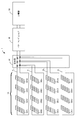
- FIG. 1 and 2 are diagrams illustrating a configuration example of the solar power generation system 1 according to the first embodiment of the present invention.
- the solar power generation system 1 includes a photovoltaic power generation (PV) panel 10, a panel controller 20, a connection box 30, a power conditioner 40, and a distribution board 50. 1, illustration of the panel controller 20 is omitted, and illustration of the connection box 30 and the distribution board 50 is omitted in FIG.
- PV photovoltaic power generation
- the PV panel 10 is a panel including a solar cell that converts light energy into electric power by the photoelectric effect.
- the PV panel 10 may be a solar battery cell that is a single solar battery or a solar battery module in which a plurality of solar batteries are combined.
- PV panel 10 is connected in series to power line PL.
- each PV panel 10 (PV panels 10A1 to 10A4, 10B1 to 10B4, 10C1 to 10C4, 10D1 to 10D4) is configured as a solar cell string (PV string) connected in series via a power line PL. Further, each solar cell string is configured as a solar cell array (PV array) connected in parallel via the power line PL. PV panel 10 is connected in series to power line PL.
- PV panel 10 is connected in series to power line PL.
- four PV panels 10 are connected in series to form a PV string, but this number is not limited to this.
- a PV array is configured by connecting four PV strings in parallel, but this number is not limited to this.
- the PV panels 10 are shown as PV panels 10A1 to 10A4, 10B1 to 10B4, 10C1 to 10C4, and 10D1 to 10D4, and the configuration and the like are all the same. In the following description, the PV panel 10 will be described unless otherwise indicated.
- the panel controller 20 inputs the generated power of the corresponding PV panel 10 and controls the generated power to be a desired power.
- the desired power is determined by a control signal related to power generation from the power conditioner 40 (a signal including information such as voltage and current), and may be different for each panel controller 20 depending on sunshine conditions and the like.
- the panel controllers 20 are shown as panel controllers 20A1 to 20A4, and the configuration and the like are all the same. In the following description, the panel controller 20 will be described unless otherwise indicated. Further, in FIG. 2, the reference numerals for the components in the panel controllers 20A2 to 20A4 are omitted, but in actuality, they are the same as the symbols for the components in the panel controller 20A1.
- the connection box 30 collects power lines PL as wiring in units of PV strings configured by connecting a plurality of PV panels 10 in series and connects the power lines PL to the power conditioner 40.
- the connection box 30 includes a terminal for connecting the power line PL, a switch used for inspection and maintenance, a lightning protection element, a backflow prevention diode for preventing a backflow of electricity, and the like. Further, the connection box 30 may be integrated with the power conditioner 40.
- the power conditioner 40 converts DC power corresponding to the power generated by each PV panel 10 output from the panel controller 20 into AC power. Further, the power conditioner 40 sends a control signal to the panel controller 20 in order to control the supply power supplied from each PV panel 10 so that the total sum of the generated power generated by each PV panel 10 is maximized. Send.
- the distribution board 50 distributes the electric power from the power conditioner 40 to each electric load (not shown).
- the panel controller 20 includes an MPPT unit 210, a communication unit 220, a switch unit SW, a coil unit 240, and a coupler 250.
- the MPPT unit 210 performs maximum power point tracking control (MPPT: Maximum Power Point Tracking) for maximizing the power generated by solar power generation in the entire solar power generation system 1.
- MPPT Maximum Power Point Tracking
- the MPPT unit 210 is connected in series to the PV panel 10 and controls the voltage between the terminals of the PV panel 10 so that the generated power of the PV panel 10 is maximized. That is, the MPPT unit 210 has a function as a voltage control unit. The detailed configuration of the MPPT unit 210 will be described later.
- the communication unit 220 is connected in parallel to the PV panel 10 and communicates various information via the power line PL.
- the communication unit 220 communicates a control signal related to power generation by the PV panel 10 with the power conditioner 40. A detailed configuration of the communication unit 220 will be described later.
- the switch unit (first switch unit) SW is connected in parallel to the communication unit 220, and is configured by an analog switch IC, for example.
- the switch unit SW is on / off controlled by electronic control by the CPU 222 (see FIG. 3) of the communication unit 220.
- the arrow in FIG. 2 shows that the panel controller 20A3 and the power conditioner 40 are communicating with each other as an example.
- the switch SW of the panel controller 20A3 is turned off (open state).
- the switch units SW of the panel controllers 20A1, 20A2, and 20A4 are turned on (closed state).
- the coil unit 240 is connected in series to the PV panel 10, and coils 241 and 242 (see FIG. 3) are arranged in each of the set of power lines PL.
- the coil unit 240 functions as a first filter unit that cuts off a frequency band in which a control signal is transmitted and passes a frequency band in which DC power is transmitted. By providing the coil unit 240, it is possible to block a signal in a high frequency band, which is a signal band, and prevent a control signal from being transmitted to the PV panel 10.
- the coupler 250 is connected in series to the communication unit 220, and includes a coil transformer 251 and coupling capacitors 252a and 252b.
- the coupler 250 functions as a second filter unit that passes the frequency band in which the control signal is transmitted and blocks the frequency band in which the DC power is transmitted.
- a DC voltage is not applied to the communication unit 220 (that is, a DC component is cut), and a signal in a signal band in which a control signal is transmitted can be passed.
- the coupling capacitors 252a and 252b also function as noise filters, and noise transmitted from the PV panel 10 to the panel controller 20 and switching noise generated in the DC / DC converter 213 of the MPPT unit 210 are transmitted to the communication unit 220. It can also be suppressed.
- the switch unit SW is preferably disposed between the communication unit 220 and the coupler 250. Thereby, a switch with a low withstand voltage can be used for switch part SW.
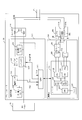
- FIG. 3 is a diagram illustrating a detailed configuration example of the MPPT unit 210 and the communication unit 220 included in the panel controller 20.
- the MPPT unit 210 includes a first voltage sensor 211, a current sensor 212, a DC / DC converter 213, a second voltage sensor 214, and a microprocessor (MPU: Micro Processing Unit) 215.
- MPU Micro Processing Unit
- the first voltage sensor 211 detects the output voltage (terminal voltage) of the PV panel 10 connected to the panel controller 20.
- the current sensor 22 detects the output current of the PV panel 10 connected to the panel controller 20.
- the DC / DC converter 213 includes a switch unit 213S having a switching element for power conversion.
- the switch unit 213S controls supply power supplied from the PV panel 10 as a power source via the power line PL by switching on and off as appropriate.
- the DC / DC converter 213 inputs the output voltage of the PV panel 10 connected to the panel controller 20, and transforms the input voltage using the switch unit 213S.
- the switch unit 213 ⁇ / b> S is on / off controlled in accordance with a PWM (Pulse Width Modulation) signal from the MPU 215.
- PWM Pulse Width Modulation
- the second voltage sensor 214 detects the output voltage (voltage after transformation) of the DC / DC converter 23. Based on the voltage detected by the first voltage sensor 211 and the current detected by the current sensor 212, the MPU 215 is instructed by the control signal received by the communication unit 220 to detect the voltage detected by the second voltage sensor 214. The duty ratio of the switch unit 213S of the DC / DC converter 213 is controlled so as to obtain a voltage value.
- the communication unit 220 includes a main IC (Integrated Circuit) 221, a memory 228, a low-pass filter (LPF) 229, a band-pass filter (BPF) 230, and a driver IC 231.
- main IC Integrated Circuit
- LPF low-pass filter
- BPF band-pass filter
- the main IC 221 includes a CPU (Central Processing Unit) 222, a PLC / MAC (Power Line Communication Media Media Control Layer) block 223, and a PLC / PHY (Power Line Communication / Physical A / D2 block).
- the main IC 221 is an integrated circuit that functions as a control circuit that performs power line communication.
- the main IC 221 is connected to the MPU 215 of the MPPT unit 210 and transmits / receives data by serial communication.
- the CPU 222 is equipped with an 8-bit RISC (Reduced Instruction Set Computer) processor.
- the PLC / MAC block 223 manages the MAC layer (Media Access Control layer) of the transmission / reception signal
- the PLC / PHY block 224 manages the PHY layer (Physical layer) of the transmission / reception signal.
- the DA converter 225 converts a digital signal into an analog signal.
- the AD converter 226 converts an analog signal into a digital signal.
- the variable amplifier 227 amplifies the signal input from the BPF 240.
- the memory 228 is a semiconductor storage device such as a RAM (Random Access Memory) or a ROM (Read Only Memory).
- the LPF 229 passes low frequency components of the signal input from the DA converter 225 and blocks other components.
- the BPF 230 allows a predetermined frequency band component of the signal input from the coupler 250 to pass and blocks other components.
- the driver IC 231 is an IC for operating a predetermined device.
- the CPU 222 uses the data stored in the memory 228 to control the operation of the PLC / MAC block 223 and the PLC / PHY block 224, and also controls the entire communication unit 220.
- the coupler 250 includes a capacitor and a transformer.
- a toroidal core 251B into which a set of power lines PL is inserted A coupler 250B configured by coupling capacitors 252a and 252b may be used.
- a clamp core may be used instead of the toroidal core 251B.
- switch unit SW is configured by an analog switch IC. Instead, as shown in FIG. 5, a switch unit SWb configured by a transistor switch may be used. .
- Communication by the communication unit 220 is roughly performed as follows. Data to be transmitted stored in the memory 228 or the like is sent to the main IC 221.
- the main IC 221 generates a digital transmission signal by performing digital signal processing on the data.
- the generated digital transmission signal is converted into an analog signal by the DA converter 225, and is output to the power line PL via the low-pass filter 229, the driver IC 231, the switch unit SW, and the coupler 250.
- the signal received from the power line PL is sent to the band pass filter 230 via the coupler 250 and the switch unit SW, and after the gain is adjusted by the variable amplifier 227, it is converted into a digital signal by the AD converter 226.
- the converted digital signal is converted into digital data by performing digital signal processing.
- the converted digital data is stored in the memory 228, for example.
- the communication unit 220 uses a single carrier signal as a transmission signal.
- the communication unit 220 converts the transmission target data into a single carrier transmission signal and outputs it, and also processes the single carrier reception signal to convert it into reception data. Digital signal processing for these conversions is mainly performed in the PLC / PHY block 224.
- the power conditioner 40 includes a power conditioner unit 410, a communication unit 420, a coil unit 430, and a coupler 440.
- the power conditioner unit 410 converts DC power corresponding to power generated by each PV panel 10 output from the panel controller 20 into AC power.
- the configurations and functions of the communication unit 420, the coil unit 430, and the coupler 440 are the same as the configurations and functions of the communication unit 220, the coil unit 240, and the coupler 250 of the panel controller 20, and a description thereof will be omitted.
- PV panels 10A1 to 10A4 shown at the top in FIG. 1 as the PV panel 10, but other PV strings (PV panels B1 to B4, PV panels) are illustrated.
- PV panels B1 to B4, PV panels PV panels
- the configuration of the PV strings including C1 to C4 and PV panels D1 to D4) is the same.
- data communication in the solar power generation system 1 will be described.
- data communication for maximum power point tracking control (MPPT control) between the panel controller 20 and the power conditioner 40 will be described. This data communication is performed at a communication timing described later.
- MPPT control maximum power point tracking control
- the power conditioner 40 operates as a parent device, and the panel controller 20 operates as a child device. That is, the power conditioner 40 manages data communication in the photovoltaic power generation system 1.
- the communication unit 420 of the power conditioner 40 includes information on the voltage (voltage information) detected by the first voltage sensor 21 of the panel controller 20 and information on the current detected by the current sensor 22 (voltage information) (via the power line PL). Control signal including current information) is received from the panel controller 20.
- the power conditioner 40 calculates the optimum voltage value of the PV panel 10 and the current value of the PV panel 10 in the PV panel 10 based on the voltage information and current information of the panel controller 20.
- the optimal voltage value and current value are the voltage value and current value of each PV panel 10 that maximizes the power in the whole of the plurality of PV panels 10.
- the optimum voltage value and current value depend on the orientation of the PV panel 10, the installation location of the PV panel 10, the weather, and the like, and may vary from PV panel 10 to PV panel 10.
- the communication unit 420 of the power conditioner 40 generates a control signal by including the calculated voltage value and current value of the PV panel 10 in the optimum voltage information and the optimum current information, and generates a control signal via the power line PL.
- This control signal is transmitted to the panel controller 20 corresponding to 10.
- the optimum power information calculated from the optimum voltage information and the optimum current information may be included in the control signal and transmitted to the panel controller 20.
- the communication unit 220 of the panel controller 20 receives the optimum voltage information and the optimum current information from the power conditioner 40 through the power line PL. Then, the panel controller 20 performs on / off control of the switch unit 213S of the DC / DC converter 213 so that the voltage value included in the received optimal voltage information and the current value included in the optimal current information are obtained.
- FIG. 6 is a diagram illustrating a configuration example of a communication frame used for data communication in the solar power generation system 1.
- a PLC frame is used for communication such as a control signal between the panel controller 20 and the power conditioner 40.
- TDMA / TDD Time Dimension Multiple Access / Time Division Duplex
- communication of 12 slots is performed in the downstream (power conditioner 40 ⁇ panel controller 20) / upward (panel controller 20 ⁇ power conditioner 40). That is, one PLC frame is composed of 24 slots. Further, since 10 msec is allocated per PLC frame, the transmission rate is 1.152 Mbps.
- beacon signal BS is transmitted from power conditioner 40 in SL0.
- the beacon signal BS is a signal for controlling communication by each panel controller 20 (specifically, the communication unit 220 of the panel controller 20 is synchronized with the communication of the communication unit 420 of the power conditioner 40).
- the data is transmitted to the panel controller 20 at regular intervals (for example, at SL0).
- the beacon signal BS is a signal with a certain pattern. Note that the beacon signal is one of the synchronization signals and one of the control signals.
- the data signal DS1 is transmitted from the power conditioner 40 to any one of the panel controllers 20.
- the data signal DS2 is transmitted from the panel controller 20 that has received the data signal DS1 to the power conditioner 40.
- the data signal DS2 also has a function as an ACK for the data signal DS1.
- the data signals DS1 and DS2 are one of control signals.
- the CPU of the communication unit 420 of the power conditioner 40 determines which slot is used to transmit a data signal from the power conditioner 40 to each of the panel controllers 20. Further, the CPU 222 of each panel controller 20 determines which slot is used to transmit a data signal from each of the panel controllers 20 to the power conditioner 40.
- the beacon signal BS includes, for example, information indicating the transmission timing at which the power conditioner 40 transmits the beacon signal BS and the data signal DS1 addressed to each panel controller 20 (for example, transmission interval information and transmission time information). . Thereby, each panel controller 20 can know the transmission timing of the beacon signal BS and the data signal DS1 addressed to itself by receiving this beacon signal BS.
- the panel controller 20 holds information indicating the transmission timing in the memory 228 of the communication unit 220 in advance. You may keep it.
- the data signal DS1 is optimal based on destination information indicating which panel controller 20 the signal is for, information for requesting each panel controller 20 to receive voltage information and current information, and voltage information and current information from the panel controller 20. Voltage information and optimum current information are included. For example, a unique ID is used as the destination information. This unique ID is managed globally like an IP address. Since the power conditioner 40 does not hold voltage information and current information from the panel controller 20 at the initial stage, the data signal DS1 does not include optimum voltage information and optimum current information.
- the data signal DS2 includes voltage information and current information of the panel controller 20 for the request signal included in the data signal DS1.
- FIG. 7 is a diagram illustrating an example of initial data communication timing and an on / off state of the switch unit SW in the photovoltaic power generation system 1.
- the panel controllers 20A1 to 20A4 communicate data signals with the power conditioner 40 in order for each frame (first frame to fourth frame). Further, it is assumed that a beacon signal is transmitted in slot SL0 for any of panel controllers 20A1 to A4.
- the switch unit SW of each panel controller 20 is configured so that the communication unit 220 can perform communication until each panel controller 20 and the power conditioner 40 perform the first series of communications, that is, at the initial stage. SW is turned off. When the first series of communication is completed, the switch unit SW is turned on.
- the time until the first series of communication is performed is, for example, until each panel controller 20 and the power conditioner 40 complete the communication of the first communication frame. Further, it may be until the reception of the beacon signal BS and the reception of the data signal DS1 by the panel controller 20 are completed. Further, it may be until the transmission of the data signal DS2 is completed after the panel controller 20 receives the data signal DS1.
- FIG. 8 is a diagram illustrating an example of normal data communication timing and an on / off state of the switch unit SW in the photovoltaic power generation system 1.
- Normal data communication refers to data communication after the first series of communications described above.
- the panel controllers 20A1 to 20A4 communicate data signals with the power conditioner 40 in order for each frame. Further, it is assumed that a beacon signal is transmitted in slot SL0 for any of panel controllers 20A1 to A4.
- each panel controller 20 receives a beacon signal BS as a synchronization signal, and determines from the destination information whether the signal is addressed to itself.
- Each panel controller 20 receives the data signal DS1 from the power conditioner 40 in the slot determined by the power conditioner 40 after receiving the beacon signal BS.
- Each panel controller 20 monitors a slot in the same frame as the received beacon signal BS, identifies an unused slot among slots (slots SL12 to SL23) for uplink communication, and the slot
- the data signal DS2 is transmitted to the power conditioner 40 in FIG.
- the CPU 222 of each panel controller 20 maintains the switch unit SW on until the timing of receiving the beacon signal BS, and immediately before receiving the beacon signal BS.
- the switch unit SW is changed to off per slot. Then, the switch unit SW is turned on around the slot immediately after receiving the beacon signal BS.
- each panel controller 20 keeps the switch section SW on until the timing for receiving the data signal DS1 determined by the power conditioner 40, and switches the slots around the slot immediately before receiving the data signal DS1.
- the part SW is changed to off.
- the switch unit SW is turned on around the slot immediately after receiving the data signal DS1.
- each panel controller 20 monitors a slot in the same frame as the received beacon signal BS, and identifies an unused slot among the slots (slots SL12 to SL23) for uplink communication, A slot for transmitting the data signal DS2 is determined. Until the timing for transmitting the determined data signal DS2, the switch unit SW is kept on, and the switch unit SW is turned off around the slot immediately before transmitting the data signal DS2. Then, the switch unit SW is turned on around the slot immediately after transmitting the data signal DS2.
- the ON / OFF state of the switch unit SW is changed for each signal (beacon signal BS, data signal DS1, data signal DS2), but the switch unit SW is turned off at least immediately before reception of the beacon signal BS,
- the switch unit SW may be turned on immediately after receiving the signal DS. That is, the change of the on / off state may be omitted immediately after reception of the beacon signal BS, immediately before reception of the data signal DS1, immediately after reception of the data signal DS1, and immediately before transmission of the data signal DS2.
- the CPU 222 of the panel controller 20 serving as the switch control unit controls the switch unit SW to be turned off during communication by the communication unit 220 and the switch unit SW to be turned on at non-communication. Accordingly, by turning on the switch unit SW when communication is not performed, the panel controller 20 itself becomes a load when another panel controller 20 is performing communication, and the power of the control signal is attenuated. Can be kept to a minimum.
- the CPU 222 of the panel controller 20 may perform control to turn on the switch unit SW when reception of the control signal by the communication unit 220 is completed. As a result, it is possible to minimize the attenuation of the power of the control signal while reliably receiving the control signal.
- the CPU 222 of the panel controller 20 may control the switch unit SW to be turned on when transmission of a response signal to the control signal by the communication unit 220 is completed. As a result, it is possible to minimize the attenuation of the power of the control signal while reliably transmitting the response signal (ACK or the like).
- each panel controller 20 performs communication in order for each frame.
- the present invention is not limited to this, and each panel SL 20 in each frame has a slot SL. You may make it use in order.
- the same signal may be communicated in consecutive slots (for example, slots SL1 to SL3). This diversity communication improves the robustness.
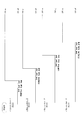
- FIG. 9 and 10 are diagrams illustrating an example of the transmission order of the data signals DS1 and DS2 in the photovoltaic power generation system 1.
- FIG. 9 and 10 are diagrams illustrating an example of the transmission order of the data signals DS1 and DS2 in the photovoltaic power generation system 1.
- signals such as PLC frames are transmitted and received in order.
- Information on the transmission order of PLC frames is held in a transmission order management table (not shown) in a memory in the communication unit 420, for example.
- a predetermined transmission order is held in the transmission order management table. For example, information indicating that PLC frames are transmitted in the order of the panel controllers 20A1, 20A2, 20A3, and 20A4 is held in advance.
- the CPU of the communication unit 420 of the power conditioner 40 transmits a PLC frame by the communication unit 420 and does not receive an ACK frame for the PLC frame
- the CPU changes the transmission order held in the transmission order management table. For example, when the reply of the second ACK frame to the second PLC frame is not confirmed, the transmission priority of the second PLC frame in the transmission order management table is lowered. For example, the transmission priority may be lowered by one or the transmission priority may be lowered.
- the frame A as the data signal DS1 is transmitted from the power conditioner 40 to the panel controller 20A1, and the ACK for the frame A as the data signal DS2 is returned from the panel controller 20A1 to the power conditioner 40. Yes.
- the CPU of the power conditioner 40 When the CPU of the power conditioner 40 confirms the reply of ACK, it updates the information in the transmission order management table.
- the transmission order since there is no ACK for which reception has not been confirmed before the ACK is returned to frame A, the transmission order is not particularly changed. Note that the update of the information in the transmission order management table here may be omitted.
- the frame B as the data signal DS1 is transmitted from the power conditioner 40 to the panel controller 20A2, but the ACK for the frame B as the data signal DS2 is not returned from the panel controller 20A2 to the power conditioner 40. .
- the frame C as the data signal DS1 is transmitted from the power conditioner 40 to the panel controller 20A3, and the ACK for the frame C as the data signal DS2 is transmitted from the panel controller 20A3 to the power conditioner 40. It has been replied.
- the CPU of the power conditioner 40 When the CPU of the power conditioner 40 confirms the reply of ACK, it updates the information in the transmission order management table.
- the transmission priority of the frame B is lowered.
- the transmission priority to the frame B that is, the panel controller 20A2 is set to the lowest.
- the frame D as the data signal DS1 is transmitted from the power conditioner 40 to the panel controller 20A4, and the ACK for the frame D as the data signal DS2 is returned from the panel controller 20A4 to the power conditioner 40.
- the CPU of the power conditioner 40 When the CPU of the power conditioner 40 confirms the reply of ACK, it updates the information in the transmission order management table.
- the change in the transmission priority of frame B has already been reflected in the transmission order management table, and there is no other ACK that could not be confirmed before the return of the ACK for frame D. Do not do. Note that the update of the information in the transmission order management table here may be omitted.
- the CPU of the power conditioner 40 retransmits the control signal to the panel controller 20 that should transmit ACK when the ACK reply cannot be confirmed. Also good.
- a control signal may be received by performing retransmission.
- FIG. 10 shows an example of the transmission order after the communication shown in FIG. 9 is performed.
- the power conditioner 40 has not confirmed the ACK reply to the frame B in FIG. That is, it is assumed that the transmission order management table holds information on the transmission order of the panel controllers 20A1 ⁇ 20A3 ⁇ 20A4 ⁇ 20A2.
- the communication unit 420 of the power conditioner 40 transmits PLC frames in the order of frame A, frame C, and frame D in accordance with the information held in the transmission order management table.
- ACK is returned from the panel controllers 20A1, 20A3, and 20A4.
- the communication unit 420 of the power conditioner 40 finally transmits the frame B to the panel controller 20A2, and receives an ACK for the frame D from the panel controller 20A2.
- transmission / reception with respect to frame B is successful in FIG.
- the communication unit 420 as the first communication unit transmits the PLC frame as the control signal in the first order to the panel controller 20 as the plurality of second power line communication devices, and the plurality of panels.
- the ACK as the response signal to the control signal
- the CPU of the communication unit 420 as the communication control unit is different from the first order and the second order
- the plurality of panel controllers The order of transmitting control signals to 20 may be changed.
- the response signal (ACK or the like) is not received, the CPU of the communication unit 420 may recognize the second order as being received after the ACK from the other panel controller 20. .
- the CPU of the communication unit 420 may control the communication unit 420 to retransmit the control signal to the panel controller 20 that should transmit this ACK. As a result, the probability of successful communication can be improved.
- the photovoltaic power generation system 1 of the present embodiment it is possible to minimize the attenuation of the power of the control signal.
- the panel controller 20 by providing switch part SW in parallel with respect to the communication part 220, when the said panel controller 20 does not communicate, the said panel controller 20 is taken from the power line PL as a distribution line. It is possible to separate. Thereby, it can prevent that the said panel controller 20 becomes a load with respect to the control signal transmitted with respect to the other panel controller 20 connected to the power line PL, and the other panel controller 20 is the power conditioner 40. This makes it easier to receive the control signal transmitted from. In addition, since retransmission of the control signal can be suppressed, communication efficiency is improved.
- FIG. 11 is a diagram illustrating a configuration example of a photovoltaic power generation system 1B according to the second embodiment of the present invention.
- the solar power generation system 1B is provided with a connection box 30B instead of the connection box 30 as compared with the solar power generation system 1 of the first embodiment shown in FIG.
- the connection box 30B includes a communication unit 310, a switch unit 320, couplers 330 and 340, and a coil unit 350.
- the distribution board 50 is not shown.
- connection box 30B corresponding to the PV string including the PV panels 10A1 to 10A4 is shown.
- connection box corresponding to each PV string is connected on the wiring. Is done.
- connection box 30 The configurations and functions of the communication unit 310, the couplers 330 and 340, and the coil unit 350 included in the connection box 30 are the same as the configurations and functions of the communication unit 220, the coupler 250, and the coil unit 240 of the panel controller 20, and thus description thereof is omitted. To do.
- connection box 30 ⁇ / b> B has a function of cutting unnecessary DC components, cutting noise, and cutting signals in a signal band in which control signals and the like are transmitted.
- the junction box 30B may be integrated with the power conditioner 40.
- the communication of the connection box 30B is performed.
- the CPU of the unit 310 can prevent signal reflection due to the wiring of the subordinate PV string by turning off the switch unit 320.
- the CPU of the communication unit 310 controls the switch unit 320 to be turned off when all the ACKs from the panel controller 20 in the PV string under the connection box 30 are received.
- the memory of the communication unit 310 grasps the PV panel 10 in the PV string under the connection box 30B by storing the unique ID of the communication unit 220 of each PV panel 10.
- the communication unit 310 can determine whether or not communication is completed for each PV panel 10 by detecting an ACK from each PV panel 10 in the subordinate PV string and analyzing the unique ID.
- the communication unit 310 When the switch unit 320 is on, the communication unit 310 is connected to the PV string under the connection box 30B, so that the panel controller 20 included in the PV string under the connection box 30B is connected via the couplers 330 and 340. Communication can be performed between the connection box 30B and the power conditioner 40.
- the CPU of the communication unit 310 of the connection box 30B turns on the switch unit 320 to reduce noise or the like. To perform efficient communication.
- the solar power generation system 1 of this embodiment includes the connection box 30B that bundles the power lines PL in units of PV strings configured by connecting PV panels 10 as a plurality of solar power generation devices in series.
- the connection box 30B is connected in series with the power conditioner 40 as the first power line communication device and the PV string under the connection box 30B, cuts off the frequency band in which the control signal is transmitted, and the DC power is
- the coil unit 350 is provided as a third filter that passes the transmitted frequency band, and the switch unit 320 as a second switch unit connected in parallel to the coil unit 350.
- connection box 30B is connected in series to the switch unit 320, and is connected in series to the communication unit 310 as a third communication unit that communicates a control signal and the switch unit 320, and transmits the control signal.
- Couplers 330 and 340 as fourth filter units that pass through the frequency band to be transmitted and block the frequency band in which the DC power is transmitted may be provided.
- the coil unit 350, the communication unit 310, the switch unit 320, and the couplers 330 and 340 are connected in parallel. Thereby, it is possible to perform desired communication with noise cut or the like.
- FIG. 12 is a diagram illustrating a configuration example of a solar power generation system 1C according to the second embodiment of the present invention.
- the photovoltaic power generation system 1C includes a panel controller 20C (20CA1 to 20CA4) that does not include the MPPT unit 210 instead of the panel controller 20. Yes.
- the connection box 30 and the distribution board 50 are not shown.
- the MPPT control by the panel controller 20C is not performed. Even when the MPPT control is not performed, it is possible to minimize the attenuation of the power of the control signal communicated between the panel controller 20 and the power conditioner 40.
- the solar power generation system 1 ⁇ / b> C information related to the power generated by each PV panel 10 (voltage value and current value of each PV panel 10) is transmitted to the power conditioner 40.
- the power conditioner 40 can grasp
- the information (electric power information) regarding electric power should just contain at least one of the voltage value and electric current value of each PV panel. This power information is included in the control signal.
- the solar power generation system 1C may include the connection box 30B described in the second embodiment.
- the MPPT control of the panel controller 20C can be omitted to prevent signal reflection due to the wiring of the subordinate PV string.
- the transmission order of the photovoltaic power generation system 1 described with reference to FIGS. 9 and 10 is the case where communication between the power conditioner 40 (master unit) and the panel controller 20 (slave unit) is via a transmission line other than the power line PL. Is also useful. As a transmission path other than the power line PL, wireless or wired such as a dedicated signal line can be considered.
- the transmission path between the power conditioner 40 and the panel controllers 20A1 to 20A4 is wired (including dedicated signal lines and power lines). ) Or wireless, the state of each transmission line is different.
- the power conditioner 40 when the power conditioner 40 does not receive the ACK frame for the control signal to the panel controller 20A2, it is estimated that the state of the transmission path between the panel controller 20A2 and the power conditioner 40 is not good. Then, the CPU of the power conditioner 40 lowers the transmission priority to the panel controller 20A2 in the transmission order management table.
- the present invention is not limited to the configuration of the above-described embodiment, and any configuration can be used as long as the functions shown in the claims or the functions of the configuration of the present embodiment can be achieved. Is also applicable.
- the present invention supplies a power line communication program for realizing the functions of the above-described embodiments to a power line communication device via a network or various storage media, and a computer (CPU) in the power line communication device reads and executes the program. Is also in scope.
- the present invention is useful for a power line communication device, a photovoltaic power generation system, a power line communication method, a power line communication program, and the like that can minimize attenuation of power of a control signal.
Landscapes
- Engineering & Computer Science (AREA)
- Computer Networks & Wireless Communication (AREA)
- Power Engineering (AREA)
- Signal Processing (AREA)
- Cable Transmission Systems, Equalization Of Radio And Reduction Of Echo (AREA)
- Remote Monitoring And Control Of Power-Distribution Networks (AREA)
- Supply And Distribution Of Alternating Current (AREA)
Abstract
Description
図1および図2は、本発明の第1の実施形態における太陽光発電システム1の構成例を示す図である。太陽光発電システム1は、太陽光発電(PV:Photo Voltaic)パネル10、パネルコントローラ20、接続箱30、パワーコンディショナ40、および分電盤50、を有して構成される。なお、図1ではパネルコントローラ20の図示が省略され、図2では接続箱30および分電盤50の図示が省略されている。
ここでは、1つのデータ通信例として、パネルコントローラ20とパワーコンディショナ40との間の最大電力点追従制御(MPPT制御)のためのデータ通信について説明する。このデータ通信は、後述する通信タイミングにおいて実施される。
図9および図10は、太陽光発電システム1におけるデータ信号DS1、DS2の送信順序の一例を示す図である。
図11は本発明の第2の実施形態における太陽光発電システム1Bの構成例を示す図である。太陽光発電システム1Bは、図2に示した第1の実施形態の太陽光発電システム1と比較すると、接続箱30に代わり、接続箱30Bを備えている。接続箱30Bは、通信部310、スイッチ部320、カプラ330、340、コイル部350を備えている。なお、図11では分電盤50の図示が省略されている。
図12は本発明の第2の実施形態における太陽光発電システム1Cの構成例を示す図である。太陽光発電システム1Cは、図2に示した第1の実施形態の太陽光発電システム1と比較すると、パネルコントローラ20に代わり、MPPT部210を備えないパネルコントローラ20C(20CA1~20CA4)を備えている。なお、図12では接続箱30および分電盤50の図示が省略されている。
図9および図10を利用して説明した太陽光発電システム1の送信順序は、パワーコンディショナ40(親機)およびパネルコントローラ20(子機)間の通信が電力線PL以外の伝送路を介する場合も有用である。電力線PL以外の伝送路としては、無線、または、専用の信号線などの有線などが考えられる。
本出願は、2011年7月28日出願の日本特許出願No.2011-165864に基づくものであり、その内容はここに参照として取り込まれる。
10、10A1~10A4、10B1~10B4、10C1~10C4、10D1~10D4、 PVパネル
20、20A1~20A4、20C、20CA1~20CA4 パネルコントローラ(子機)
210 MPPT部
211 第1電圧センサ
212 電流センサ
213 DC/DCコンバータ
213S スイッチ部
214 第2電圧センサ
215 MPU
220 通信部
221 メインIC
222 CPU
223 PLC・MACブロック
224 PLC・PHYブロック
225 DAC
226 ADC
227 VGA
228 メモリ
229 LDF
230 BPF
231 ドライバIC
240 コイル部
241、242 コイル
250、250B カプラ
251 コイルトランス
251B トロイダルコア
252a、252b カップリング用コンデンサ
30、30B 接続箱
310 通信部
320 スイッチ部
330、340 カプラ
350 コイル部
40 パワーコンディショナ(親機)
410 パワーコンディショナ部
420 通信部
430 コイル部
440 カプラ
SW、SWb スイッチ部
PL 電力線
Claims (18)
- 電力線に対して直列に接続された太陽光発電装置に対して並列に接続され、前記電力線を介して、前記太陽光発電装置による発電に関する制御信号を通信する通信部と、
前記通信部に対して並列に接続されたスイッチ部と、
を備える電力線通信装置。 - 請求項1に記載の電力線通信装置であって、更に、
前記通信部による通信時に前記スイッチ部をオフにし、前記通信部による非通信時に前記スイッチ部をオンにするよう制御するスイッチ制御部を備える電力線通信装置。 - 請求項2に記載の電力線通信装置であって、
前記スイッチ制御部は、前記通信部による前記制御信号の受信が完了したときに、前記スイッチ部をオンにするよう制御する電力線通信装置。 - 請求項3に記載の電力線通信装置であって、
前記スイッチ制御部は、前記通信部による前記制御信号に対する応答信号の送信が完了したときに、前記スイッチ部をオンにするよう制御する電力線通信装置。 - 請求項1ないし4のいずれか1項に記載の電力線通信装置であって、更に、
前記太陽光発電装置に対して直列に接続され、前記制御信号が伝送される周波数帯域を遮断し直流電力が伝送される周波数帯域を通過させる第1のフィルタ部を備える電力線通信装置。 - 請求項1ないし5のいずれか1項に記載の電力線通信装置であって、更に、
前記太陽光発電装置に対して直列に接続され、前記太陽光発電装置による発電電力が最大となるよう前記太陽光発電装置の端子間電圧を制御する電圧制御部を備える電力線通信装置。 - 請求項1ないし6のいずれか1項に記載の電力線通信装置であって、更に、
前記通信部に対して直列に接続され、前記制御信号が伝送される周波数帯域を通過させ直流電力が伝送される周波数帯域を遮断する第2のフィルタ部を備える電力線通信装置。 - 請求項7に記載の電力線通信装置であって、
前記スイッチ部は、前記通信部と前記第2のフィルタ部との間に接続された電力線通信装置。 - 請求項1ないし8のいずれか1項に記載の電力線通信装置であって、
前記制御信号は、前記太陽光発電装置が発電した電力情報を含む電力線通信装置。 - 請求項9に記載の電力線通信装置であって、
前記電力情報は、前記太陽光発電装置が発電する電力の電圧値および電力値の少なくとも一方である電力線通信装置。 - 電力線に対して直列接続された複数の太陽光発電装置と、前記複数の太陽光発電装置を制御する第1の電力線通信装置と、前記複数の太陽光発電装置の各々に接続された複数の第2の電力線通信装置と、を備える太陽光発電システムであって、
前記第1の電力線通信装置は、
前記電力線を介して、前記太陽光発電装置による発電に関する制御信号を前記複数の第2の電力線通信装置に送信する第1の通信部を備え、
前記第2の電力線通信装置は、
前記電力線を介して、前記第1の電力線通信装置から前記制御信号を受信する第2の通信部と、
前記第2の通信部に対して並列に接続された第1のスイッチ部と、
を備える太陽光発電システム。 - 請求項11に記載の太陽光発電システムであって、
前記第1の電力線通信装置は、前記第1の通信部を制御する通信制御部を備え、
前記第1の通信部は、前記複数の第2の電力線通信装置に対して第1の順番で前記制御信号を送信し、前記複数の第2の電力線通信装置から前記制御信号に対する応答信号を第2の順番で受信し、
前記通信制御部は、前記第1の順番と前記第2の順番とが異なる場合、前記複数の第2の電力線通信装置に対して前記制御信号を送信する順番を前記第2の順番に更新する太陽光発電システム。 - 請求項11に記載の太陽光発電システムであって、
前記通信制御部は、前記第1の通信部により前記応答信号が受信されなかった場合、当該応答信号を送信すべき第2の電力線通信装置に対して前記制御信号を再送するよう、前記第1の通信部を制御する太陽光発電システム。 - 請求項11ないし13のいずれか1項に記載の太陽光発電システムであって、更に、
前記複数の太陽光発電装置が直列に接続されて構成される太陽電池ストリング単位で前記電力線を束ねる接続箱を備え、
前記接続箱は、前記第1の電力線通信装置と当該接続箱の配下の太陽電池ストリングとに対して直列に接続され、前記制御信号が伝送される周波数帯域を遮断し直流電力が伝送される周波数帯域を通過させる第3のフィルタ部と、前記第3のフィルタ部に対して並列に接続された第2のスイッチ部と、を備える太陽光発電システム。 - 請求項14に記載の太陽光発電システムであって、
前記接続箱は、前記第2のスイッチ部に対して直列に接続され、前記制御信号を通信する第3の通信部と、前記第2のスイッチ部に対して直列に接続され、前記制御信号が伝送される周波数帯域を通過させ直流電力が伝送される周波数帯域を遮断する第4のフィルタ部と、を備え、
前記第3のフィルタ部と、前記第3の通信部、前記第2のスイッチ部、および前記第4のフィルタ部とは、並列に接続された太陽光発電システム。 - 請求項14または15に記載の太陽光発電システムであって、
前記第3の通信部は、前記接続箱の配下の太陽電池ストリング内の太陽光発電装置の第2の通信部から送信される応答信号を全て受信すると、前記第2のスイッチ部をオフにするよう制御する太陽光発電システム。 - 電力線を介して通信を行う電力線通信装置における電力線通信方法であって、
前記電力線に対して直列に接続された太陽光発電装置に対して並列に接続された通信部により、前記電力線を介して、前記太陽光発電装置による発電に関する制御信号を通信するステップと、
前記通信部に対して並列に接続されたスイッチ部を、通信時にオフにし、非通信時にオンにするよう制御するステップと、
を有する電力線通信方法。 - 請求項17に記載の電力線通信方法の各ステップをコンピュータに実行させるための電力線通信プログラム。
Priority Applications (3)
| Application Number | Priority Date | Filing Date | Title |
|---|---|---|---|
| CN201280036913.8A CN103703647A (zh) | 2011-07-28 | 2012-07-13 | 电力线通信装置、太阳能发电系统、电力线通信方法、以及电力线通信程序 |
| US14/234,095 US20140161201A1 (en) | 2011-07-28 | 2012-07-13 | Power line communication device, solar power generation system, power line communication method, and power line communication program |
| EP12817967.8A EP2725678A4 (en) | 2011-07-28 | 2012-07-13 | Power line communication device, solar power generation system, power line communication method, and power line communication program |
Applications Claiming Priority (2)
| Application Number | Priority Date | Filing Date | Title |
|---|---|---|---|
| JP2011165864 | 2011-07-28 | ||
| JP2011-165864 | 2011-07-28 |
Publications (1)
| Publication Number | Publication Date |
|---|---|
| WO2013014879A1 true WO2013014879A1 (ja) | 2013-01-31 |
Family
ID=47600755
Family Applications (1)
| Application Number | Title | Priority Date | Filing Date |
|---|---|---|---|
| PCT/JP2012/004555 WO2013014879A1 (ja) | 2011-07-28 | 2012-07-13 | 電力線通信装置、太陽光発電システム、電力線通信方法、及び電力線通信プログラム |
Country Status (5)
| Country | Link |
|---|---|
| US (1) | US20140161201A1 (ja) |
| EP (1) | EP2725678A4 (ja) |
| JP (1) | JPWO2013014879A1 (ja) |
| CN (1) | CN103703647A (ja) |
| WO (1) | WO2013014879A1 (ja) |
Cited By (14)
| Publication number | Priority date | Publication date | Assignee | Title |
|---|---|---|---|---|
| JP5547311B1 (ja) * | 2013-02-06 | 2014-07-09 | 株式会社日立アドバンストデジタル | 太陽光発電設備のための監視システム |
| US20140265551A1 (en) * | 2013-03-14 | 2014-09-18 | Hiq Solar, Inc. | Measurement, control and harvest optimization device for solar modules requiring fewer connections |
| WO2014140251A1 (fr) * | 2013-03-15 | 2014-09-18 | Mersen France Sb Sas | Système et procédé de communication bas débit à courant porteur |
| WO2015052052A1 (de) * | 2013-10-07 | 2015-04-16 | Sma Solar Technology Ag | Multistring-photovoltai k-wechselrichter mit erkennung von zwischengeschalteten dc/dc stellern zur deaktivierung des internen mppt |
| KR20150077889A (ko) * | 2013-12-30 | 2015-07-08 | 윤윤화 | 다중 전원을 이용한 유무선 통합형 태양광 발전모니터링 장치 |
| EP2916466A1 (en) * | 2014-03-05 | 2015-09-09 | Thomson Licensing | Electrical activity sensor device for detecting electrical activity and electrical activity monitoring apparatus |
| JP2017532743A (ja) * | 2014-10-02 | 2017-11-02 | ローベルト ボッシュ ゲゼルシャフト ミット ベシュレンクテル ハフツング | パワースイッチ、バッテリシステム、及び、パワースイッチを駆動する方法 |
| WO2020183700A1 (ja) * | 2019-03-14 | 2020-09-17 | オムロン株式会社 | 制御装置、及び太陽光発電システム |
| WO2022203474A1 (ko) * | 2021-03-26 | 2022-09-29 | 엘지이노텍 주식회사 | 멀티레벨 구조를 가지는 전력변환장치 |
| WO2022203475A1 (ko) * | 2021-03-26 | 2022-09-29 | 엘지이노텍 주식회사 | 멀티레벨 구조를 가지는 전력변환장치 |
| WO2022203476A1 (ko) * | 2021-03-26 | 2022-09-29 | 엘지이노텍 주식회사 | 멀티레벨 구조를 가지는 전력변환장치 |
| JP2022550138A (ja) * | 2019-09-29 | 2022-11-30 | ファーウェイ デジタル パワー テクノロジーズ カンパニー リミテッド | 電力線通信に適用されるインタフェース回路、ストリング及びシステム |
| WO2023277672A1 (ko) * | 2021-07-02 | 2023-01-05 | 엘지이노텍 주식회사 | 멀티레벨 구조를 가지는 전력변환장치 |
| WO2023277653A1 (ko) * | 2021-07-01 | 2023-01-05 | 엘지이노텍 주식회사 | 멀티레벨 구조를 가지는 전력변환장치 |
Families Citing this family (15)
| Publication number | Priority date | Publication date | Assignee | Title |
|---|---|---|---|---|
| KR20140123854A (ko) * | 2013-04-15 | 2014-10-23 | 한국전자통신연구원 | 직렬 연결된 전력선 통신 장치 및 방법 |
| EP2866354B1 (en) * | 2013-10-25 | 2019-06-26 | VITO NV (Vlaamse Instelling voor Technologisch Onderzoek NV) | Method and system for providing pulsed power and data on a bus |
| CN104184492B (zh) * | 2014-07-31 | 2016-08-24 | 中国农业大学 | 电力系统中功率与通信信号复合通信的方法及装置 |
| WO2016123305A1 (en) * | 2015-01-28 | 2016-08-04 | Abb Technology Ag | Energy panel arrangement shutdown |
| CN105049087B (zh) * | 2015-08-31 | 2017-10-24 | 山东中大电源科技有限公司 | 基于非互连直流线路的电力载波系统 |
| SE539911C2 (en) * | 2015-11-18 | 2018-01-09 | Optistring Tech Ab | Common line communication in cascaded inverters |
| CN106981881A (zh) | 2016-01-18 | 2017-07-25 | 台达电子企业管理(上海)有限公司 | 一种光伏发电系统及其快速关断方法 |
| CN105591670A (zh) * | 2016-03-12 | 2016-05-18 | 吕海峰 | 基于电力线通信的光伏组件状态信息监控装置及监控方法 |
| CN105867513B (zh) * | 2016-03-30 | 2017-07-28 | 北方工业大学 | 一种扰动观察最大功率点的跟踪装置 |
| CN106130422B (zh) * | 2016-08-12 | 2018-12-28 | 江苏苏美达机电有限公司 | 基于电力载波通信的发电机控制装置与控制方法 |
| US11398749B2 (en) * | 2017-05-22 | 2022-07-26 | Solaredge Technologies Ltd. | Method and apparatus to enable communication and control in a power system |
| EP3780402A4 (en) * | 2018-03-30 | 2021-12-29 | Zeon Corporation | Power distribution network device |
| EP3584946A1 (en) * | 2018-06-19 | 2019-12-25 | Fronius International GmbH | A photovoltaic module level monitoring system |
| CN110572184B (zh) | 2019-08-02 | 2021-03-05 | 华为技术有限公司 | 发电系统及用于发电系统的通信装置 |
| ES2862461A1 (es) * | 2020-04-06 | 2021-10-07 | Univ Valladolid | Sistema de comunicaciones sobre cableado de corriente continua en instalaciones solares fotovoltaicas |
Citations (4)
| Publication number | Priority date | Publication date | Assignee | Title |
|---|---|---|---|---|
| JPH10201105A (ja) * | 1997-01-14 | 1998-07-31 | Nissin Electric Co Ltd | 太陽光発電装置 |
| JP2008072751A (ja) * | 2007-10-31 | 2008-03-27 | Matsushita Electric Works Ltd | 電力線搬送通信用配線システム |
| JP2010512139A (ja) * | 2006-12-06 | 2010-04-15 | ソーラーエッジ エルティーディ | Dc電源を用いた分散型電力ハーベストシステムの監視システム及び方法 |
| JP2010186795A (ja) * | 2009-02-10 | 2010-08-26 | Sony Corp | 光電池装置、および故障判定方法 |
Family Cites Families (8)
| Publication number | Priority date | Publication date | Assignee | Title |
|---|---|---|---|---|
| US4430639A (en) * | 1981-05-21 | 1984-02-07 | Benvar Associates, C/O Dale Bennett | Visual message intercommunication unit and system |
| US7193872B2 (en) * | 2005-01-28 | 2007-03-20 | Kasemsan Siri | Solar array inverter with maximum power tracking |
| US7813842B2 (en) * | 2006-03-09 | 2010-10-12 | Sony Corporation | Systems and methods for use in providing local power line communication |
| TWM308574U (en) * | 2006-07-05 | 2007-03-21 | Ding-Yin Chiou | Household self-provided power supply |
| DE102008008503A1 (de) * | 2008-02-11 | 2009-08-20 | Siemens Aktiengesellschaft | PV-Teilgenerator-Anschlusskasten, PV-Generator-Anschlusskasten und PV-Wechselrichter für eine PV-Anlage sowie PV-Anlage |
| US9077206B2 (en) * | 2008-05-14 | 2015-07-07 | National Semiconductor Corporation | Method and system for activating and deactivating an energy generating system |
| US8487634B2 (en) * | 2008-09-25 | 2013-07-16 | Enmetric Systems, Inc. | Smart electrical wire-devices and premises power management system |
| CN201893732U (zh) * | 2010-12-08 | 2011-07-06 | 何峰 | 网络化光伏发电系统 |
-
2012
- 2012-07-13 JP JP2013525567A patent/JPWO2013014879A1/ja not_active Withdrawn
- 2012-07-13 WO PCT/JP2012/004555 patent/WO2013014879A1/ja active Application Filing
- 2012-07-13 US US14/234,095 patent/US20140161201A1/en not_active Abandoned
- 2012-07-13 EP EP12817967.8A patent/EP2725678A4/en not_active Withdrawn
- 2012-07-13 CN CN201280036913.8A patent/CN103703647A/zh active Pending
Patent Citations (4)
| Publication number | Priority date | Publication date | Assignee | Title |
|---|---|---|---|---|
| JPH10201105A (ja) * | 1997-01-14 | 1998-07-31 | Nissin Electric Co Ltd | 太陽光発電装置 |
| JP2010512139A (ja) * | 2006-12-06 | 2010-04-15 | ソーラーエッジ エルティーディ | Dc電源を用いた分散型電力ハーベストシステムの監視システム及び方法 |
| JP2008072751A (ja) * | 2007-10-31 | 2008-03-27 | Matsushita Electric Works Ltd | 電力線搬送通信用配線システム |
| JP2010186795A (ja) * | 2009-02-10 | 2010-08-26 | Sony Corp | 光電池装置、および故障判定方法 |
Non-Patent Citations (1)
| Title |
|---|
| See also references of EP2725678A4 * |
Cited By (26)
| Publication number | Priority date | Publication date | Assignee | Title |
|---|---|---|---|---|
| JP2014155271A (ja) * | 2013-02-06 | 2014-08-25 | Hitachi Advanced Digital Inc | 太陽光発電設備のための監視システム |
| JP5547311B1 (ja) * | 2013-02-06 | 2014-07-09 | 株式会社日立アドバンストデジタル | 太陽光発電設備のための監視システム |
| US20140265551A1 (en) * | 2013-03-14 | 2014-09-18 | Hiq Solar, Inc. | Measurement, control and harvest optimization device for solar modules requiring fewer connections |
| EP2973993A4 (en) * | 2013-03-14 | 2016-11-16 | Hiq Solar Inc | MEASUREMENT, CONTROL AND EARNING OPTIMIZATION DEVICE FOR SOLAR MODULES WITH LESS CONNECTIONS |
| CN105164915A (zh) * | 2013-03-14 | 2015-12-16 | Hiq太阳能股份有限公司 | 用于需要较少连接的太阳能模块的测量、控制和收集优化设备 |
| CN105103459A (zh) * | 2013-03-15 | 2015-11-25 | 梅森法国Sb公司 | 在载波电流上进行低数据速率通信的系统和方法 |
| WO2014140251A1 (fr) * | 2013-03-15 | 2014-09-18 | Mersen France Sb Sas | Système et procédé de communication bas débit à courant porteur |
| FR3003417A1 (fr) * | 2013-03-15 | 2014-09-19 | Mersen France Sb Sas | Systeme et procede de communication bas debit a courant porteur |
| WO2015052052A1 (de) * | 2013-10-07 | 2015-04-16 | Sma Solar Technology Ag | Multistring-photovoltai k-wechselrichter mit erkennung von zwischengeschalteten dc/dc stellern zur deaktivierung des internen mppt |
| KR20150077889A (ko) * | 2013-12-30 | 2015-07-08 | 윤윤화 | 다중 전원을 이용한 유무선 통합형 태양광 발전모니터링 장치 |
| KR101591575B1 (ko) * | 2013-12-30 | 2016-02-03 | 윤윤화 | 다중 전원을 이용한 유무선 통합형 태양광 발전모니터링 장치 |
| EP2916466A1 (en) * | 2014-03-05 | 2015-09-09 | Thomson Licensing | Electrical activity sensor device for detecting electrical activity and electrical activity monitoring apparatus |
| US9785809B2 (en) | 2014-03-05 | 2017-10-10 | Thomson Licensing | Electrical activity sensor device for detecting electrical activity and electrical activity monitoring apparatus |
| JP2015171154A (ja) * | 2014-03-05 | 2015-09-28 | トムソン ライセンシングThomson Licensing | 電気的アクティビティを検出する電気的アクティビティ・センサ装置および電気的アクティビティ監視装置 |
| JP2017532743A (ja) * | 2014-10-02 | 2017-11-02 | ローベルト ボッシュ ゲゼルシャフト ミット ベシュレンクテル ハフツング | パワースイッチ、バッテリシステム、及び、パワースイッチを駆動する方法 |
| JP7367752B2 (ja) | 2019-03-14 | 2023-10-24 | オムロン株式会社 | 制御装置、及び太陽光発電システム |
| WO2020183700A1 (ja) * | 2019-03-14 | 2020-09-17 | オムロン株式会社 | 制御装置、及び太陽光発電システム |
| JPWO2020183700A1 (ja) * | 2019-03-14 | 2021-12-16 | オムロン株式会社 | 制御装置、及び太陽光発電システム |
| US11886217B2 (en) | 2019-03-14 | 2024-01-30 | Omron Corporation | Control device and solar power generation system |
| JP7397976B2 (ja) | 2019-09-29 | 2023-12-13 | ファーウェイ デジタル パワー テクノロジーズ カンパニー リミテッド | 電力線通信に適用されるインタフェース回路、ストリング及びシステム |
| JP2022550138A (ja) * | 2019-09-29 | 2022-11-30 | ファーウェイ デジタル パワー テクノロジーズ カンパニー リミテッド | 電力線通信に適用されるインタフェース回路、ストリング及びシステム |
| WO2022203475A1 (ko) * | 2021-03-26 | 2022-09-29 | 엘지이노텍 주식회사 | 멀티레벨 구조를 가지는 전력변환장치 |
| WO2022203476A1 (ko) * | 2021-03-26 | 2022-09-29 | 엘지이노텍 주식회사 | 멀티레벨 구조를 가지는 전력변환장치 |
| WO2022203474A1 (ko) * | 2021-03-26 | 2022-09-29 | 엘지이노텍 주식회사 | 멀티레벨 구조를 가지는 전력변환장치 |
| WO2023277653A1 (ko) * | 2021-07-01 | 2023-01-05 | 엘지이노텍 주식회사 | 멀티레벨 구조를 가지는 전력변환장치 |
| WO2023277672A1 (ko) * | 2021-07-02 | 2023-01-05 | 엘지이노텍 주식회사 | 멀티레벨 구조를 가지는 전력변환장치 |
Also Published As
| Publication number | Publication date |
|---|---|
| EP2725678A4 (en) | 2014-09-10 |
| US20140161201A1 (en) | 2014-06-12 |
| EP2725678A1 (en) | 2014-04-30 |
| CN103703647A (zh) | 2014-04-02 |
| JPWO2013014879A1 (ja) | 2015-02-23 |
Similar Documents
| Publication | Publication Date | Title |
|---|---|---|
| WO2013014879A1 (ja) | 電力線通信装置、太陽光発電システム、電力線通信方法、及び電力線通信プログラム | |
| JP5906401B2 (ja) | 電力線通信装置、電力線通信システム、電力線通信方法、及び電力線通信プログラム | |
| JP3215387U (ja) | 太陽光発電モジュールのための監視・停止装置 | |
| US9453861B2 (en) | Renewable energy monitoring system | |
| US20120181865A1 (en) | Distributed dc power systems | |
| WO2010062662A2 (en) | Systems and methods for using a power converter for transmission of data over the power feed | |
| WO2005117136A3 (de) | Photovoltaikanlage zur einspeisung in ein elektrisches netz sowie zentrales steuer-und überwachungsgerät für eine photovoltaikanlage | |
| KR101819235B1 (ko) | 병렬 통신 장치 | |
| EP2595319A1 (en) | Wireless switch assembly, relay retransmission control system and memory card | |
| EP2976825B1 (en) | Dc power distribution system | |
| CN101877166A (zh) | 一种监测太阳电池组件板工作状态数据的方法 | |
| KR20190125149A (ko) | 태양광 모듈 정션 박스, 태양광 시스템 및 태양광 모듈 제어 방법 | |
| US9921597B2 (en) | Power control apparatus, power control system, and control method | |
| US20150334793A1 (en) | Master-slave system on the secondary side of a galvanic isolation barrier (selv barrier) of an operating unit | |
| US9769779B2 (en) | Radio base station, radio communication network system, and communication control method | |
| CN208424310U (zh) | 一种太阳能组件接线盒及太阳能系统 | |
| US20220166251A1 (en) | Methods and arrangements for load control | |
| CN110417348A (zh) | 太阳能组件接线盒、太阳能系统及太阳能组件控制方法 | |
| CN106302521B (zh) | 一种协议转换器 | |
| CN105720913A (zh) | 太阳能光伏组件用安全断开接线盒及电站系统 | |
| US20140350700A1 (en) | Power control apparatus, power control system, and control method | |
| CN108418621A (zh) | 无线中继器 | |
| Gupta et al. | Smart LED Lighting using GaN-based “Discrete” Power and Data Sequential Co-Transfer Network | |
| JP5789742B2 (ja) | 分電盤 | |
| Di Zenobio et al. | EDISON: An innovative lighting architecture facilitating building automation |
Legal Events
| Date | Code | Title | Description |
|---|---|---|---|
| 121 | Ep: the epo has been informed by wipo that ep was designated in this application |
Ref document number: 12817967 Country of ref document: EP Kind code of ref document: A1 |
|
| ENP | Entry into the national phase |
Ref document number: 2013525567 Country of ref document: JP Kind code of ref document: A |
|
| WWE | Wipo information: entry into national phase |
Ref document number: 14234095 Country of ref document: US Ref document number: 2012817967 Country of ref document: EP |
|
| NENP | Non-entry into the national phase |
Ref country code: DE |