以下に、本発明にかかる実施の形態について、図面を参照しながら説明する。
Embodiments according to the present invention will be described below with reference to the drawings.
(実施の形態1)
以下に、本発明にかかる実施の形態1における垂直軸型マグナス式風力発電機について説明する。
(Embodiment 1)
Below, the vertical axis | shaft type Magnus type | formula wind power generator in Embodiment 1 concerning this invention is demonstrated.
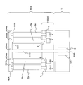
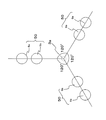
図1は、本発明にかかる実施の形態1における垂直軸型マグナス式風力発電機の斜視構成図である。又、図2は、図1のXX´間の断面構成図である。図1及び図2に示すように、本実施の形態1の垂直軸型マグナス式風力発電機は、台座1と、台座1の上側に回転可能に配置された風車部2とを備えている。そして、台座1内には発電機3が配置されており、発電機3には、鉛直上方に発電機回転軸3aが設けられており、この発電機回転軸3aが発電機3と風車部2を連結している。この発電機3はインナーロータ型の発電機であり、発電機回転軸3aの下部分が回転子100であり、その外側に固定子101が設けられている。そして、風車部2が回転することにより、発電機回転軸3aが回転し、発電機3が発電を行う。尚、この発電機回転軸3aが、本発明の縦軸の一例に対応する。
FIG. 1 is a perspective configuration diagram of a vertical axis type Magnus-type wind power generator according to Embodiment 1 of the present invention. FIG. 2 is a cross-sectional view taken along the line XX ′ in FIG. As shown in FIGS. 1 and 2, the vertical axis Magnus type wind power generator according to the first embodiment includes a pedestal 1 and a windmill portion 2 that is rotatably disposed on the pedestal 1. A generator 3 is disposed in the pedestal 1, and the generator 3 is provided with a generator rotating shaft 3 a vertically above. The generator rotating shaft 3 a is connected to the generator 3 and the windmill unit 2. Are connected. The generator 3 is an inner rotor type generator, and a lower portion of the generator rotating shaft 3a is a rotor 100, and a stator 101 is provided outside thereof. When the windmill unit 2 rotates, the generator rotating shaft 3a rotates, and the generator 3 generates power. The generator rotating shaft 3a corresponds to an example of the vertical axis of the present invention.
上記風車部2には、水平に配置された円板形状の支持部材4が設けられており、支持部材4の中心に発電機回転軸3aが固定されている。支持部材4には、計8本の円柱形状のバレル5が配置されている。図3は、8本のバレル5の配置を示す平面構成図である。
The windmill portion 2 is provided with a disk-shaped support member 4 disposed horizontally, and a generator rotating shaft 3 a is fixed to the center of the support member 4. A total of eight columnar barrels 5 are arranged on the support member 4. FIG. 3 is a plan configuration diagram showing the arrangement of the eight barrels 5.
これら8本のバレル5は、その支持軸6が支持部材4の表面に対して垂直になるように、2本一組で配置されている。この2本のバレル5は、支持部材4の中心4a(発電機回転軸3a)から円周方向に向かう半径上(二点鎖線で示す)に配置されている。すなわち、バレル組50のうち外側に配置されているバレル5aと発電機回転軸3aの間に、内側のバレル5bが配置されていることになる。この外側に配置されているバレル5aと、その内側に配置されているバレル5bをバレル組50として、4つのバレル組50が、発電機回転軸3aを中心にして等間隔に配置されている。そして、4つのバレル組50の4つのバレル5bは、中心4aの同心円上に配置されており、4つのバレル5aは、中心4aの同心円上に配置されている。又、8本のバレル5は、支持軸6によって支持部材4に形成された軸受部4bに自転可能に軸支されている。尚、内側のバレル5aと外側のバレル5bは同じ大きさであり、それぞれを区別する必要がない場合は、バレル5と記載する。
These eight barrels 5 are arranged in pairs so that the support shaft 6 is perpendicular to the surface of the support member 4. The two barrels 5 are arranged on a radius (indicated by a two-dot chain line) from the center 4a (generator rotating shaft 3a) of the support member 4 in the circumferential direction. That is, the inner barrel 5b is disposed between the barrel 5a disposed on the outer side of the barrel set 50 and the generator rotating shaft 3a. The barrel 5a arranged outside and the barrel 5b arranged inside the barrel 5b are used as a barrel set 50, and four barrel sets 50 are arranged at equal intervals around the generator rotating shaft 3a. The four barrels 5b of the four barrel sets 50 are arranged on concentric circles at the center 4a, and the four barrels 5a are arranged on concentric circles at the center 4a. Further, the eight barrels 5 are pivotally supported by a support shaft 6 on a bearing portion 4b formed on the support member 4 so as to be capable of rotating. The inner barrel 5a and the outer barrel 5b have the same size, and are referred to as the barrel 5 when it is not necessary to distinguish between them.
次に、本発明に関連する発明の第1の伝達機構の一例について図2を参照して説明する。
Next, an example of the first transmission mechanism of the invention related to the present invention will be described with reference to FIG.
図2に示すように、1つのバレル組50において、内側のバレル5bの支持軸6には、バレル5bの下側に第1ギア7が設けられており、外側のバレル5aの支持軸6には、バレル5aの下側に第2ギア8が設けられている。これら第1ギア7と第2ギア8は噛み合っている。また、バレル5aよりも外側の支持部材4上にはモータ9が配置されており、このモータ9の駆動軸9aに駆動ギア10が設けられている。そして、駆動ギア10と第2ギア8が噛み合っており、モータ9の駆動力が、第2ギア8及び第1ギア7に伝達される。すなわち、モータ9を駆動させることによって、バレル5a、5bは、それぞれ自転することになるが、バレル5aとバレル5bの自転方向は反対方向となる。尚、モータ9への給電は、スリップリングによって行われる。又、4つのバレル組50は全て同じ構成となっている。又、第1ギア7、第2ギア8及びモータ9を覆うように、支持部材4の上にはカバー部材11が設けられている。
As shown in FIG. 2, in one barrel set 50, the support shaft 6 of the inner barrel 5b is provided with a first gear 7 below the barrel 5b, and the support shaft 6 of the outer barrel 5a is connected to the support shaft 6 of the outer barrel 5a. The second gear 8 is provided below the barrel 5a. The first gear 7 and the second gear 8 are engaged with each other. A motor 9 is disposed on the support member 4 outside the barrel 5 a, and a drive gear 10 is provided on a drive shaft 9 a of the motor 9. The drive gear 10 and the second gear 8 mesh with each other, and the driving force of the motor 9 is transmitted to the second gear 8 and the first gear 7. That is, by driving the motor 9, the barrels 5a and 5b rotate, but the rotation directions of the barrels 5a and 5b are opposite to each other. The power supply to the motor 9 is performed by a slip ring. All four barrel groups 50 have the same configuration. A cover member 11 is provided on the support member 4 so as to cover the first gear 7, the second gear 8 and the motor 9.
又、モータ9によるバレル5の自転を制御する自転制御部12と、発電機回転軸3aの回転数を検出する回転数検出部16と、発電機3を外部電力により動力源として用いるために、発電機3を動力源に切り替える切替部14と、切替部14を動作することによって発電機回転軸3aの動作を制御する発電機制御部17とを備えている。又、カバー部材11の上側には、風速計15と温度計18及び感雪計19が設けられている。
In order to use the rotation control unit 12 for controlling the rotation of the barrel 5 by the motor 9, the rotation number detection unit 16 for detecting the rotation number of the generator rotation shaft 3a, and the generator 3 as a power source by external power, A switching unit 14 that switches the generator 3 to a power source and a generator control unit 17 that controls the operation of the generator rotating shaft 3a by operating the switching unit 14 are provided. Further, an anemometer 15, a thermometer 18, and a snow gauge 19 are provided on the upper side of the cover member 11.
尚、本発明に関連する発明の停止検出部の一例は、本実施の形態の回転数検出部16に対応する。
Note that an example of the stop detection unit of the invention related to the present invention corresponds to the rotation speed detection unit 16 of the present embodiment.
上記構成の本実施の形態1の垂直軸型マグナス式風力発電機の動作について説明する。
The operation of the vertical axis Magnus type wind power generator of the first embodiment configured as described above will be described.
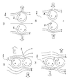
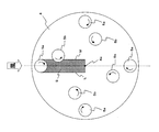
図4は、本実施の形態1の垂直軸型マグナス式風力発電機の動作を説明するための平面構成図である。
FIG. 4 is a plan configuration diagram for explaining the operation of the vertical axis type Magnus type wind power generator according to the first embodiment.
図4に示すように、本実施の形態1の垂直軸型マグナス式風力発電機では、外側のバレル5aは、平面視において時計回り(矢印B)に自転し、内側のバレル5bは、平面視において反時計回り(矢印C)に自転している。ここで、図4では、風の向きが矢印Aによって示されており、風上側のバレル組50を50aとし、時計回りに順に50b、50c、50dとする。
As shown in FIG. 4, in the vertical axis type Magnus type wind power generator of the first embodiment, the outer barrel 5a rotates in the clockwise direction (arrow B) in a plan view, and the inner barrel 5b has a plan view. Rotate counterclockwise (arrow C). Here, in FIG. 4, the direction of the wind is indicated by an arrow A, and the barrel set 50 on the windward side is set to 50a, and is set to 50b, 50c, and 50d in order clockwise.
図5(a)~(d)は、それぞれのバレル組50a~50bにおけるバレル5a、5bの自転と風向きとマグナス力の関係を示す図である。
FIGS. 5 (a) to 5 (d) are diagrams illustrating the relationship between the rotation of the barrels 5a and 5b, the wind direction, and the Magnus force in each barrel set 50a to 50b.
図5(a)に示すように、バレル組50aの外側のバレル5aの右側では、風速にバレル5aの自転速度が加わり流速が速くなる。一方、バレル5aの左側では、風速からバレル5aの自転速度が減らされ流速が遅くなる。このため、バレル5aでは、右方向へのマグナス力(矢印V1)が発生することになる。
As shown in FIG. 5 (a), on the right side of the barrel 5a outside the barrel set 50a, the rotation speed of the barrel 5a is added to the wind speed to increase the flow velocity. On the other hand, on the left side of the barrel 5a, the rotation speed of the barrel 5a is reduced from the wind speed, and the flow velocity becomes slower. For this reason, in the barrel 5a, a Magnus force (arrow V1) in the right direction is generated.
又、バレル組50aの内側のバレル5bの左側では、風速にバレル5bの自転速度が加わり流速が速くなり、バレル5bの右側では、風速からバレル5bの自転速度が減らされ流速が遅くなる。このため、バレル5bでは、左方向へのマグナス力(矢印V2)が発生することになる。
Also, on the left side of the barrel 5b inside the barrel set 50a, the rotation speed of the barrel 5b is added to the wind speed to increase the flow velocity, and on the right side of the barrel 5b, the rotation speed of the barrel 5b is decreased from the wind speed and the flow velocity is decreased. For this reason, in the barrel 5b, a Magnus force (arrow V2) in the left direction is generated.
ここで、マグナス力は、風速と、バレルの自転角速度と、バレルの直径とに比例することが知られている。図5(a)に示すバレル組50aの位置では、バレル5bは、バレル5aの風下に配置されているため、気流の少なくとも一部がバレル5aにより遮蔽されるので、バレル5aの方が、その風下側に配置されているバレル5bよりも発生するマグナス力が大きくなる。よって、2本のバレル5a、5bが発生するマグナス力の合力は、右方向に向き、支持部材4を介して発電機回転軸3aを時計回りに回転させる。
Here, it is known that the Magnus force is proportional to the wind speed, the rotational angular velocity of the barrel, and the diameter of the barrel. At the position of the barrel set 50a shown in FIG. 5 (a), the barrel 5b is disposed leeward of the barrel 5a, so that at least a part of the airflow is shielded by the barrel 5a. The Magnus force generated is larger than that of the barrel 5b arranged on the leeward side. Therefore, the resultant force of the Magnus force generated by the two barrels 5 a and 5 b is directed rightward and rotates the generator rotating shaft 3 a clockwise via the support member 4.
又、図5(b)に示すバレル組50bの位置では、バレル5aに右方向のマグナス力(矢印V3)が発生し、バレル5bに左方向のマグナス力(矢印V4)が発生するが、バレル5aとバレル5bに届く風の風速は同じであるため、マグナス力も打ち消し合うことになる。尚、製造誤差等によりどちらか一方のマグナス力が大きくなったとしても、半径方向に沿った力であるため、風車部2を回転させる力とはならない。
Further, at the position of the barrel set 50b shown in FIG. 5B, a rightward Magnus force (arrow V3) is generated in the barrel 5a, and a leftward Magnus force (arrow V4) is generated in the barrel 5b. Since the wind speeds of the winds reaching the 5a and the barrel 5b are the same, the Magnus forces are canceled out. Even if one of the Magnus forces increases due to a manufacturing error or the like, it is a force along the radial direction, and thus does not become a force for rotating the windmill portion 2.
又、図5(c)に示すバレル組50cの位置では、そのバレル5aの右側では、風速にバレル5aの自転速度が加えられ流速が速くなり、バレル5aの左側では、風速からバレル5aの自転速度が減らされ流速が遅くなる。このため、バレル5aでは、右方向へのマグナス力(矢印V6)が発生することになる。
In the position of the barrel set 50c shown in FIG. 5C, on the right side of the barrel 5a, the rotation speed of the barrel 5a is added to the wind speed to increase the flow velocity, and on the left side of the barrel 5a, the rotation of the barrel 5a from the wind speed is performed. The speed is reduced and the flow rate is reduced. For this reason, in the barrel 5a, a Magnus force (arrow V6) in the right direction is generated.
一方、バレル組50cの内側のバレル5bの右側では、風速からバレル5bの自転速度が減らされ流速が遅くなり、バレル5bの左側では、風速にバレル5bの自転速度が加えられ流速が速くなる。このため、バレル5bでは、左方向へのマグナス力(矢印V5)が発生することになる。
On the other hand, on the right side of the barrel 5b inside the barrel set 50c, the rotation speed of the barrel 5b is reduced from the wind speed and the flow velocity becomes slow, and on the left side of the barrel 5b, the rotation speed of the barrel 5b is added to the wind speed and the flow velocity becomes high. For this reason, in the barrel 5b, a Magnus force (arrow V5) in the left direction is generated.
ここで、図5(c)に示すバレル組50cの位置では、バレル5bの方が、その風下側に配置されているバレル5aよりも発生するマグナス力が大きくなる。そのため、バレル組50aは、左方向に動くことになり、支持部材4を介して発電機回転軸3aを時計回りに回転させる。
Here, at the position of the barrel set 50c shown in FIG. 5C, the barrel 5b has a larger Magnus force generated than the barrel 5a arranged on the leeward side. Therefore, the barrel set 50 a moves in the left direction, and rotates the generator rotating shaft 3 a clockwise via the support member 4.
又、図5(d)に示すバレル組50dの位置では、バレル5aに右方向のマグナス力(矢印V8)が発生し、バレル5bに左方向のマグナス力(矢印V7)が発生するが、バレル5aとバレル5bに届く風の風速は同じであるため、マグナス力も打ち消し合うことになる。
Further, at the position of the barrel set 50d shown in FIG. 5D, a rightward Magnus force (arrow V8) is generated in the barrel 5a and a leftward Magnus force (arrow V7) is generated in the barrel 5b. Since the wind speeds of the winds reaching the 5a and the barrel 5b are the same, the Magnus forces are canceled out.
以上のように、図4に示す位置では、バレル組50aの位置では、右方向の力が発生し、バレル組50cの位置では、左方向の力が発生する。すなわち、バレル組50が発電機回転軸3aよりも風上側の領域にあるとき、バレル組50に発生するマグナス力は、支持部材4を、発電機回転軸3aを中心として時計回りに公転させる方向であり、バレル組50が発電機回転軸3aよりも風下側の領域にあるときも、支持部材4を、発電機回転軸3aを中心として時計回りに公転させる方向にマグナス力が働く。そのため、風車部2は、平面視において、時計回り(矢印D参照)に回転する。
As described above, at the position shown in FIG. 4, a rightward force is generated at the position of the barrel set 50a, and a leftward force is generated at the position of the barrel set 50c. That is, when the barrel set 50 is in the region on the windward side of the generator rotating shaft 3a, the Magnus force generated in the barrel set 50 causes the support member 4 to revolve clockwise around the generator rotating shaft 3a. Even when the barrel set 50 is in the region on the leeward side with respect to the generator rotation shaft 3a, the Magnus force acts in the direction of revolving the support member 4 clockwise around the generator rotation shaft 3a. Therefore, the windmill unit 2 rotates clockwise (see arrow D) in plan view.
この風車部2の回転により、発電機回転軸3aが回転し、発電機3で発電が行われる。このとき、発電機回転軸3aの回転数が、回転数検出部16によって検出され、その検出された回転数に応じて、自転制御部12が、バレル5の自転の回転速度を適切に制御する。又、風速計15によって検出された風速によって、バレル5の自転の回転速度を制御してもよい。
The rotation of the wind turbine unit 2 causes the generator rotating shaft 3a to rotate, and the generator 3 generates power. At this time, the rotation speed of the generator rotation shaft 3a is detected by the rotation speed detection unit 16, and the rotation control unit 12 appropriately controls the rotation speed of the barrel 5 according to the detected rotation speed. . Further, the rotational speed of rotation of the barrel 5 may be controlled by the wind speed detected by the anemometer 15.
次に、風が弱い又は無風のため、発電機回転軸3aが回転していない状態における制御ついて説明する。
Next, control in a state where the generator rotating shaft 3a is not rotating due to weak wind or no wind will be described.
風速計15によって、計測される風速が第1の所定風速未満の場合には、一定時間毎に、発電機制御部17は、切替部14を制御し、発電機3を動力源として用いて、発電機回転軸3aを所定時間の間、第1の所定の回転速度で回転させる。又、同時に、自転制御部12によって、バレル5が第1の所定回転速度以上の回転速度で自転するように制御が行われる方がより好ましい。
When the wind speed measured by the anemometer 15 is less than the first predetermined wind speed, the generator control unit 17 controls the switching unit 14 and uses the generator 3 as a power source at regular intervals. The generator rotating shaft 3a is rotated at a first predetermined rotation speed for a predetermined time. At the same time, it is more preferable that the rotation control unit 12 performs control so that the barrel 5 rotates at a rotation speed equal to or higher than the first predetermined rotation speed.
このように制御することによって、第1の所定風速未満の弱風が吹いた場合であっても、風車部2が回転しやすくなり、発電状態に移行出来る。
By controlling in this way, the wind turbine unit 2 can be easily rotated even when a weak wind less than the first predetermined wind speed is blown, and the power generation state can be shifted.
尚、風速が、第1の所定風速よりも小さい第2の所定風速未満である場合には、ほぼ無風であることから、発電機回転軸3aを回転させる動力が無駄になると判断し、発電機回転軸3aを駆動しないように制御が行われる。このときは、バレル5の自転も行われない。上気第2の所定風速とは、バレル5を自転させても発電機回転軸3aが回転しない風速であり、例えば、風速1m/sである。又、第1の所定風速とは、バレル5の自転だけでは風車部2が回転しないが、上記のように発電機回転軸3aを第1の回転速度で駆動させることによって、発電状態に移行することが可能な風速であり、例えば3m/sである。
When the wind speed is less than the second predetermined wind speed, which is smaller than the first predetermined wind speed, it is determined that the power for rotating the generator rotating shaft 3a is wasted because it is almost no wind. Control is performed so as not to drive the rotating shaft 3a. At this time, the barrel 5 is not rotated. The upper predetermined second wind speed is a wind speed at which the generator rotating shaft 3a does not rotate even when the barrel 5 rotates, and is, for example, a wind speed of 1 m / s. Further, the first predetermined wind speed means that the wind turbine unit 2 does not rotate only by the rotation of the barrel 5, but the generator rotation shaft 3a is driven at the first rotation speed as described above to shift to the power generation state. Is the possible wind speed, for example 3 m / s.
次に、積雪・凍結防止の際の制御について説明する。
Next, the control for preventing snow accumulation and freezing will be described.
感雪計19によって、積雪が感知され、且つ発電可能な風速である(発電運転を行っている)場合には、自転制御部12は、一定時間毎に、バレル5を第2の所定の回転速度以上の回転速度で、予め決められた時間、自転させるように制御を行う。ここで、第2の所定の回転速度は、発電時の制御による回転数よりも速い回転速度である。このように、一定時間毎に予め決められた時間、高速でバレル5を自転させることにより、バレル5上の積雪を落下させることが出来る。尚、風速計により発電可能な風速であるかを検出する代わりに、回転数検出部16によって発電機回転軸3aが回転しており、発電されていることが検知されてもよい。
When snow is detected by the snow meter 19 and the wind speed is such that power can be generated (power generation operation is being performed), the rotation control unit 12 rotates the barrel 5 at a second predetermined rotation every predetermined time. Control is performed to rotate at a rotational speed equal to or higher than the speed for a predetermined time. Here, the second predetermined rotation speed is a rotation speed faster than the rotation speed by the control during power generation. Thus, the snow on the barrel 5 can be dropped by rotating the barrel 5 at a high speed for a predetermined time every predetermined time. Instead of detecting whether the wind speed can be generated by the anemometer, the rotation speed detection unit 16 may detect that the generator rotating shaft 3a is rotating and generating electricity.
感雪計19によって、積雪が感知され、且つ発電不可能な風速(例えば、上記第2の風速以下)である場合、発電機制御部17は、一定時間毎に切替部14を動作し、発電機3を動力源に切替え、発電機回転軸3aを所定時間の間、第2の回転速度で駆動させるように制御を行う。尚、このとき、自転制御部12は、一定時間毎に、バレル5を第2の所定の回転速度以上の回転速度で、予め決められた時間、自転させるように制御を行う。
When the snow sensor 19 senses snow and the wind speed is not capable of generating power (for example, the second wind speed or less), the generator control unit 17 operates the switching unit 14 at regular intervals to generate power. The machine 3 is switched to the power source, and control is performed so that the generator rotating shaft 3a is driven at the second rotation speed for a predetermined time. At this time, the rotation control unit 12 performs control so that the barrel 5 rotates at a rotation speed equal to or higher than the second predetermined rotation speed for a predetermined time at regular time intervals.
また、温度計18によって、凍結の可能性のある温度であることが検知され、且つ発電不可能な風速(例えば、上記第2の風速以下)である場合、発電機制御部17は、一定時間毎に切替部14を動作し、発電機3を動力源に切替え、発電機回転軸3aを所定時間の間、第2の回転速度で駆動させるように制御を行う。尚、このとき、自転制御部12によって、バレル5を第3の所定の回転速度以下の速度で自転させる制御が行われる。
If the thermometer 18 detects that the temperature is likely to freeze and the wind speed is not possible to generate power (for example, the second wind speed or less), the generator controller 17 Every time the switching unit 14 is operated, the generator 3 is switched to the power source, and the generator rotating shaft 3a is controlled to be driven at the second rotational speed for a predetermined time. At this time, the rotation control unit 12 performs control to rotate the barrel 5 at a speed equal to or lower than a third predetermined rotation speed.
上記発電機回転軸3aの第2の所定の回転速度は、低速である。又、バレル5の第3の所定の回転速度は、第2の所定の回転速度よりも遅い低速である。このように発電が行われていない時でも、発電機回転軸3a及びバレル5を低速で回転させることにより、凍結を防止することが出来る。
The second predetermined rotation speed of the generator rotation shaft 3a is a low speed. Further, the third predetermined rotation speed of the barrel 5 is a lower speed than the second predetermined rotation speed. Even when power generation is not performed in this manner, freezing can be prevented by rotating the generator rotating shaft 3a and the barrel 5 at a low speed.
以上のように、本実施の形態1の垂直軸型マグナス式風力発電機は、風上側のバレル組50と風下側のバレル組50におけるバレル5の回転を利用しているため、発電効率が高くなる。
As described above, the vertical axis Magnus type wind power generator according to the first embodiment uses the rotation of the barrel 5 in the windward-side barrel set 50 and the leeward-side barrel set 50, and thus has high power generation efficiency. Become.
又、バレル5a、5bの自転方向は常に同じ回転方向でよいため、特許文献3のように、自転方向を切り替える必要がなく、制御が簡易になる。
Also, since the rotation direction of the barrels 5a and 5b may always be the same rotation direction, it is not necessary to switch the rotation direction as in Patent Document 3, and the control becomes simple.
まとめると、2本のバレル5a、5bが発電機回転軸3aよりも風上側の領域にあるとき、バレル5aに発生するマグナス力は、支持部材4を発電機回転軸3aを中心として時計回りに公転させる方向であり、バレル5bに発生するマグナス力は、支持部材4を発電機回転軸3aを中心として反時計回りに公転させる方向である。
In summary, when the two barrels 5a and 5b are in the region on the windward side of the generator rotation shaft 3a, the Magnus force generated in the barrel 5a causes the support member 4 to rotate clockwise around the generator rotation shaft 3a. It is a direction to revolve, and the Magnus force generated in the barrel 5b is a direction to revolve the support member 4 counterclockwise around the generator rotation shaft 3a.
このとき、バレル5bは、バレル5aの風下にあるため、気流の少なくとも一部がバレル5aにより遮蔽されるので、バレル5bが発生するマグナス力は、バレル5aが発生するマグナス力よりも小さくなる。
At this time, since the barrel 5b is leeward of the barrel 5a, at least a part of the airflow is shielded by the barrel 5a, so the Magnus force generated by the barrel 5b is smaller than the Magnus force generated by the barrel 5a.
よって、2本のバレル5a、5bが発生するマグナス力の合力は、支持部材4を介して
発電機回転軸3aを時計回りに回転させる。
Therefore, the resultant force of the Magnus force generated by the two barrels 5 a and 5 b rotates the generator rotating shaft 3 a clockwise via the support member 4.
発電機回転軸3aが回転し、2本のバレル5a、5bが発電機回転軸3aよりも風下側の領域に移動したとき、バレル5aに発生するマグナス力は、支持部材4を反時計回りに公転させる方向となり、バレル5bに発生するマグナス力は、支持部材4を時計回りに公転させる方向となる。このとき、バレル5aは、バレル5bの風下にあるため、気流の少なくとも一部がバレル5bにより遮蔽されるので、バレル5aが発生するマグナス力は、バレル5bが発生するマグナス力よりも小さくなる。
When the generator rotating shaft 3a rotates and the two barrels 5a and 5b move to a region leeward from the generator rotating shaft 3a, the Magnus force generated in the barrel 5a causes the support member 4 to rotate counterclockwise. The direction of revolving is caused, and the Magnus force generated in the barrel 5b is the direction of revolving the support member 4 clockwise. At this time, since the barrel 5a is leeward of the barrel 5b, at least a part of the airflow is shielded by the barrel 5b, so the Magnus force generated by the barrel 5a is smaller than the Magnus force generated by the barrel 5b.
よって、2本のバレル5a、5bが発生するマグナス力の合力は、支持部材を介して発電機回転軸を時計回りに回転させる。
Therefore, the resultant force of the Magnus force generated by the two barrels 5a and 5b rotates the generator rotating shaft clockwise through the support member.
つまり、風下側のバレルを遮蔽したり、バレルの自転回転数を個別かつ頻繁に変動させることなく、発電機回転軸の風上側と風下側両方の気流を利用して、発電機に一方向の回転力を発生できる。
In other words, without blocking the leeward barrel or changing the rotation speed of the barrel individually and frequently, the airflow on both the leeward side and the leeward side of the generator rotating shaft is used to allow the generator to Can generate rotational force.
また、風速または発電機回転軸の回転数を計測し、それを基にバレルの自転回転数を変化させ、バレルに発生するマグナス力を調整することで、発電機回転軸の回転トルクを制御できる。
In addition, the rotational speed of the generator rotating shaft can be controlled by measuring the wind speed or the rotating speed of the generator rotating shaft, changing the rotating speed of the barrel based on that, and adjusting the Magnus force generated in the barrel. .
具体的には、微風時にはバレルの自転回転数を高くし、強風時には低くすることで、起動性が良好となり、また広い風速域において発電可能となる。
Specifically, by increasing the rotation speed of the barrel during light winds and decreasing it during strong winds, the start-up performance is improved and power generation is possible in a wide wind speed range.
又、本実施の形態1の4つのバレル組50のバレル5の自転回転数制御は一律に行えば良い。
Further, the rotation speed control of the barrels 5 of the four barrel sets 50 of the first embodiment may be performed uniformly.
又、先行文献である特許文献3の構成では、以下のような問題点があった。バレルの自転回転数を個別かつ頻繁に変動させるためエネルギーロスが大きくなる。また、バレルには慣性モーメントがあるので、風速と風向が頻繁に変動するような場合、バレルの自転回転数の制御が追従できなくなり、発電効率が低下する可能性がある。バレルの慣性モーメントは、風力発電機を大型化する場合に特に問題となる。バレルの慣性モーメントは半径の2乗に比例して大きくなり、自転回転数制御に対するバレルの応答性が悪くなるので、風向や風速の変動に対して追従させるために高出力のモータが必要となり、エネルギーロスが大きくなる上、モータ及びバレルにかかる負荷も大きくなる。さらに、風向の計測手段、アジマス角計測手段などが加わることで装置が複雑となるので、製造コストとメンテナンスコストが高くなる。
Further, the configuration of Patent Document 3 which is a prior document has the following problems. Energy loss increases because the rotational speed of the barrel varies individually and frequently. In addition, since the barrel has a moment of inertia, when the wind speed and the wind direction fluctuate frequently, the control of the rotation speed of the barrel cannot follow and power generation efficiency may be reduced. The moment of inertia of the barrel is particularly problematic when the wind power generator is enlarged. The moment of inertia of the barrel increases in proportion to the square of the radius, and the response of the barrel to the rotation speed control becomes worse. Therefore, a high-output motor is required to follow fluctuations in the wind direction and wind speed. The energy loss increases and the load on the motor and barrel also increases. Furthermore, since the apparatus becomes complicated by adding a wind direction measuring unit, an azimuth angle measuring unit, etc., the manufacturing cost and the maintenance cost increase.
しかしながら、本実施の形態の垂直軸型マグナス式風力発電機では、以上のように、バレルの配置と自転方向を工夫することにより、風向の影響を受けず、発電効率が高く、起動性が良好で、広い風速域において発電可能であり、強風に対する安全性が高く、大型化が容易で、ビルや家屋などの屋上へ設置可能であり、又は低コストで製造及び運用可能となる。
However, in the vertical axis type Magnus wind power generator of the present embodiment, as described above, by devising the arrangement of the barrel and the rotation direction, it is not affected by the wind direction, has high power generation efficiency, and has good startability. Thus, power generation is possible in a wide wind speed range, safety against strong winds is high, the size can be easily increased, and the system can be installed on the roof of a building or a house, or can be manufactured and operated at low cost.
(実施の形態2)
次に、本発明にかかる実施の形態2における垂直軸型マグナス式風力発電機について説明する。本実施の形態2における垂直軸型マグナス式風力発電機は、実施の形態1と基本的な構成は同じであるが、バレルを下側で支持する支持部材の構成、及びバレルを上側で支持する上側支持部材が追加されている点等が異なっている。そのため、本相違点を中心に説明する。尚、実施の形態1と同様の構成については同一の符号が付されている。
(Embodiment 2)
Next, the vertical axis type Magnus type wind power generator according to the second embodiment of the present invention will be described. The vertical axis Magnus type wind power generator according to the second embodiment has the same basic configuration as that of the first embodiment, but supports the barrel on the lower side and supports the barrel on the upper side. The difference is that an upper support member is added. Therefore, this difference will be mainly described. In addition, the same code | symbol is attached | subjected about the structure similar to Embodiment 1. FIG.
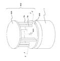
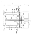
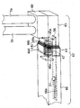
図6は、本実施の形態2の垂直軸型マグナス式風力発電機の斜視構成図である。又、図7は、図6のZZ´間の断面構成図である。尚、図6及び図7では、自転制御部12と、回転数検出部16と、切替部14と、発電機制御部17、風速計15、温度計18、及び感雪計19は省略している。
FIG. 6 is a perspective configuration diagram of the vertical axis type Magnus type wind power generator according to the second embodiment. FIG. 7 is a cross-sectional view taken along the line ZZ ′ in FIG. 6 and 7, the rotation control unit 12, the rotation speed detection unit 16, the switching unit 14, the generator control unit 17, the anemometer 15, the thermometer 18, and the snow gauge 19 are omitted. Yes.
図6及び図7に示すように、本実施の形態2の垂直軸型マグナス式風力発電機の風車部602には、バレル5の上側を支持するための円板状の上側支持部材606が設けられており、更に、風車部602の中心に縦軸603が設けられている。この縦軸603の下部が、回転子100となっており、本実施の形態2では一体に形成されているが別々に形成され、下側支持部材604を介して連結されていても良い。本実施の形態2では、バレル5の上側には支持軸609が設けられており、この支持軸609は、上側支持部材606の軸受け部606bに回転可能に嵌められている。そして、縦軸603も上側支持部材606の下側中央部に形成された軸受け部606cに回転可能に嵌められている。
As shown in FIGS. 6 and 7, the windmill portion 602 of the vertical axis Magnus type wind power generator according to the second embodiment is provided with a disk-like upper support member 606 for supporting the upper side of the barrel 5. Furthermore, a vertical axis 603 is provided at the center of the windmill portion 602. The lower portion of the vertical axis 603 is the rotor 100 and is integrally formed in the second embodiment, but may be separately formed and connected via the lower support member 604. In the second embodiment, a support shaft 609 is provided on the upper side of the barrel 5, and the support shaft 609 is rotatably fitted to the bearing portion 606 b of the upper support member 606. The vertical axis 603 is also rotatably fitted to a bearing part 606c formed at the lower center part of the upper support member 606.
次に、本実施の形態2の、バレル5の下側に配置されている下側支持部材604が、実施の形態1の支持部材4と構造が異なっている点について説明する。
Next, the point that the lower support member 604 disposed on the lower side of the barrel 5 of the second embodiment is different in structure from the support member 4 of the first embodiment will be described.
図7に示すように、本実施の形態2では、下側の下側支持部材604は中空の円板状の部材であり、その天井部分604sに支持軸6を支持する軸受け部604bが形成されている。そして、支持軸6の下端に第1ギア7又は第2ギア8が設けられている。すなわち、支持軸6は、バレル5と第1ギア7又は第2ギア8との間で、下側支持部材604の天井部分604sで支持されている。
As shown in FIG. 7, in the second embodiment, the lower lower support member 604 is a hollow disk-shaped member, and a bearing portion 604b that supports the support shaft 6 is formed on the ceiling portion 604s. ing. A first gear 7 or a second gear 8 is provided at the lower end of the support shaft 6. That is, the support shaft 6 is supported by the ceiling portion 604 s of the lower support member 604 between the barrel 5 and the first gear 7 or the second gear 8.
又、実施の形態1では、モータ9の駆動ギア10は、第2ギア8と噛み合っていたが、本実施の形態2では、モータ9の駆動ギア10は、第1ギア7と噛み合っている。バレル組50毎に設けられたモータ9によって第1ギア7及び第8ギアが回転し、バレル5が回転することになる。
In the first embodiment, the drive gear 10 of the motor 9 is engaged with the second gear 8. In the second embodiment, the drive gear 10 of the motor 9 is engaged with the first gear 7. The first gear 7 and the eighth gear are rotated by the motor 9 provided for each barrel set 50, and the barrel 5 is rotated.
以上のように、本実施の形態2では、上下方向からバレル5を支持することにより、バレルを安定して支持することが可能となる。
As described above, in the second embodiment, it is possible to stably support the barrel by supporting the barrel 5 from above and below.
尚、本実施の形態2の構成の上側支持部材606及び縦軸603を実施の形態1に適用しても良い。
The upper support member 606 and the vertical axis 603 having the configuration of the second embodiment may be applied to the first embodiment.
尚、本実施の形態2では、上側支持部材606及び下側支持部材604が円板形状であったが、この形状に限らず十字形状であってもよい。図8は、そのような構成の垂直軸型マグナス式風力発電機の斜視構成図である。図8に示す風車部612では、下側支持部材614及び上側支持部材616が十字形状に形成されている。下側支持部材614及び上側支持部材616は、それぞれ中央部614a、616aと、中央部614a、616aから四方に伸びたアーム部614b、616bを有している。隣り合うアーム部によって形成される角度は、直角になっている。そして、1つのアーム部614bと1つのアーム部616bの先端に挟まれて、2つのバレル5が支持されている。
In the second embodiment, the upper support member 606 and the lower support member 604 are disk-shaped, but are not limited to this shape, and may be cross-shaped. FIG. 8 is a perspective configuration diagram of the vertical axis Magnus type wind power generator having such a configuration. In the wind turbine unit 612 shown in FIG. 8, the lower support member 614 and the upper support member 616 are formed in a cross shape. The lower support member 614 and the upper support member 616 have center portions 614a and 616a and arm portions 614b and 616b extending in four directions from the center portions 614a and 616a, respectively. The angle formed by the adjacent arm portions is a right angle. The two barrels 5 are supported by being sandwiched between the tips of one arm portion 614b and one arm portion 616b.
又、上記実施の形態1、2では、バレル組50毎にモータ9が設けられていたが、バレル5毎にモータ9が設けられていても良い。図9は、このような垂直軸型マグナス式風力発電機の正面から視た断面構成図である。図9に示す垂直軸型マグナス式風力発電機では、本実施の形態2と異なり、モータ9が支持軸6毎に設けられており、支持軸6には、第1ギア7又は第2ギア8が設けられていない。
In the first and second embodiments, the motor 9 is provided for each barrel set 50, but the motor 9 may be provided for each barrel 5. FIG. 9 is a cross-sectional configuration diagram of such a vertical axis type Magnus type wind power generator viewed from the front. In the vertical axis type Magnus type wind power generator shown in FIG. 9, unlike the second embodiment, a motor 9 is provided for each support shaft 6, and the first gear 7 or the second gear 8 is provided on the support shaft 6. Is not provided.
(実施の形態3)
次に、本発明にかかる実施の形態3における垂直軸型マグナス式風力発電機について説明する。本実施の形態3の垂直軸型マグナス式風力発電機は、実施の形態1と基本的な構成は同じであるが、バレル5を自転させる構成が異なっている。そのため、本相違点を中心に説明する。尚、実施の形態1と同様の構成については同一の符号が付されている。
(Embodiment 3)
Next, the vertical axis type Magnus wind turbine generator according to the third embodiment of the present invention will be described. The vertical axis type Magnus wind power generator according to the third embodiment has the same basic configuration as that of the first embodiment, but is different in the configuration for rotating the barrel 5. Therefore, this difference will be mainly described. In addition, the same code | symbol is attached | subjected about the structure similar to Embodiment 1. FIG.
実施の形態1では、バレル5を自転させるモータ9が、バレル組50ごとに設けられており、計4個配置されていたが、本実施の形態3では、モータが1個のみ設けられており、この1個のモータで、全てのバレル5を自転させる構成となっている。
In the first embodiment, the motor 9 for rotating the barrel 5 is provided for each barrel set 50, and a total of four motors are arranged. However, in the third embodiment, only one motor is provided. This single motor is configured to rotate all the barrels 5.
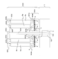
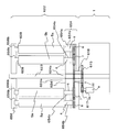
図10は、本実施の形態3の垂直軸型マグナス式風力発電機の正面断面構成図である。図11は、図10のYY´間の断面構成図である。
FIG. 10 is a front cross-sectional configuration diagram of the vertical axis Magnus wind turbine generator according to the third embodiment. FIG. 11 is a cross-sectional configuration diagram along YY ′ in FIG. 10.
図10及び図11に示すように、本実施の形態3の垂直軸型マグナス式風力発電機では、バレル組50のそれぞれに対応するモータ9は設けられておらず、1つのモータ20が設けられている。このモータ20からバレル5への伝達機構が、本発明に関連する発明の第2の伝達機構の一例に対応する。以下に、この伝達機構について説明する。
As shown in FIGS. 10 and 11, in the vertical axis Magnus type wind power generator of the third embodiment, the motor 9 corresponding to each of the barrel sets 50 is not provided, and one motor 20 is provided. ing. The transmission mechanism from the motor 20 to the barrel 5 corresponds to an example of the second transmission mechanism of the invention related to the present invention. The transmission mechanism will be described below.
モータ20から鉛直上向き方向に配置されているモータ軸20aの先端には、駆動ギア21が設けられている。そして、複数の第1ギア7と噛み合うように、それらの中央に中央ギア22が配置されており、この中央ギア22と駆動ギア21が噛み合っている。尚、中央ギア22は、支持軸22aによって、支持部材4の軸受部4bに回転可能に軸支されており、支持軸22aは、支持部材4の中心4a上に設けられている。
A driving gear 21 is provided at the tip of the motor shaft 20a arranged vertically upward from the motor 20. A central gear 22 is arranged at the center of the plurality of first gears 7 so as to mesh with the plurality of first gears 7, and the central gear 22 and the driving gear 21 are meshed with each other. The central gear 22 is rotatably supported by the bearing portion 4b of the support member 4 by a support shaft 22a. The support shaft 22a is provided on the center 4a of the support member 4.
このような構成により、モータ20を動作させると、モータ軸20aが回転し、モータ軸20aに固定されている駆動ギア21により中央ギア22が回転し、4つの第1ギア7が回転する。そして、それぞれの第1ギア7と噛み合っている第2ギア8も回転する。
With such a configuration, when the motor 20 is operated, the motor shaft 20a is rotated, the central gear 22 is rotated by the drive gear 21 fixed to the motor shaft 20a, and the four first gears 7 are rotated. And the 2nd gear 8 meshed | engaged with each 1st gear 7 also rotates.
本実施の形態3では、1つのモータで全てのバレル5を回転させる構成であるため、1つのモータを制御するだけで、全てのバレル5の自転の回転速度を制御することが可能となり、より制御が容易となる。
In this Embodiment 3, since it is the structure which rotates all the barrels 5 with one motor, it becomes possible to control the rotational speed of rotation of all the barrels 5 only by controlling one motor. Control becomes easy.
(実施の形態4)
次に、本発明にかかる実施の形態4における垂直軸型マグナス式風力発電機について説明する。本実施の形態4は、実施の形態3のように1つのモータによって全てのバレルを自転させる構成であるが、モータ9が台座側に配置されている点が異なっている。そのため、本相違点を中心に説明する。尚、上記実施の形態1、2と同様の構成については同一の符号が付されている。
(Embodiment 4)
Next, a vertical axis type Magnus wind turbine generator according to Embodiment 4 of the present invention will be described. The fourth embodiment is a configuration in which all barrels are rotated by one motor as in the third embodiment, except that the motor 9 is arranged on the pedestal side. Therefore, this difference will be mainly described. In addition, the same code | symbol is attached | subjected about the structure similar to the said Embodiment 1,2.
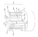
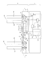
図12は、本発明にかかる実施の形態4の垂直軸型マグナス式風力発電機の正面から視た断面構成図である。尚、図12では、自転制御部12と、回転数検出部16と、切替部14と、発電機制御部17、風速計15、温度計18、及び感雪計19は省略している。
FIG. 12 is a cross-sectional configuration diagram seen from the front of the vertical axis type Magnus type wind power generator according to the fourth embodiment of the present invention. In FIG. 12, the rotation control unit 12, the rotation speed detection unit 16, the switching unit 14, the generator control unit 17, the anemometer 15, the thermometer 18, and the snow gauge 19 are omitted.
図12に示すように、本実施の形態4の垂直軸型マグナス式風力発電機の風車部612では、実施の形態2の構成の風車部602のように上側支持部材606、下側支持部材644、及び縦軸603が設けられており、下側支持部材644の天井部644sに形成された軸受け部644bで、支持軸6が支持されている。そして、実施の形態3と同様に、下側支持部材644内に中央ギア22が配置されている。この中央ギア22の中央に形成された貫通孔内に縦軸603が配置されており、中央ギア22は、縦軸603に固定されておらず、縦軸603に対して回転自在に構成されている。
As shown in FIG. 12, in the wind turbine unit 612 of the vertical axis type Magnus type wind power generator of the fourth embodiment, the upper support member 606 and the lower support member 644 are similar to the wind turbine unit 602 having the configuration of the second embodiment. , And a vertical axis 603, and the support shaft 6 is supported by a bearing portion 644 b formed on the ceiling portion 644 s of the lower support member 644. As in the third embodiment, the center gear 22 is disposed in the lower support member 644. A vertical axis 603 is disposed in a through hole formed in the center of the central gear 22, and the central gear 22 is not fixed to the vertical axis 603 but is configured to be rotatable with respect to the vertical axis 603. Yes.
又、台座1内には、中央ギア22と同軸に台座内中央ギア615が設けられている。この台座内中央ギア615も、中央ギア22と同様に、その中央に形成された貫通孔内に縦軸603が配置された構成であり、縦軸603に固定されておらず、縦軸603に対して回転自在に構成されている。そして、台座内中央ギア615と中央ギア22は、連結部材618によって連結されており、同時に回転する。このように中央ギア22と連結した台座内中央ギア615と噛み合うように駆動ギア617が設けられており、この駆動ギア617は、モータ9の駆動軸9aに固定されている。
Also, a pedestal central gear 615 is provided coaxially with the central gear 22 in the pedestal 1. The central gear 615 in the pedestal also has a configuration in which a vertical axis 603 is disposed in a through hole formed at the center thereof, similarly to the central gear 22, and is not fixed to the vertical axis 603, and is not fixed to the vertical axis 603. In contrast, it is configured to be rotatable. Then, the pedestal central gear 615 and the central gear 22 are connected by a connecting member 618 and rotate simultaneously. A drive gear 617 is provided so as to mesh with the in-pedestal center gear 615 connected to the center gear 22 in this manner, and this drive gear 617 is fixed to the drive shaft 9 a of the motor 9.
以上のように構成することで、モータ9の回転を駆動ギア617及び台座内中央ギア615を介して、中央ギア22に伝達することが出来るため、上記実施の形態3と同様に、1つのモータで全てのバレルを自転させることが可能となる。
With the configuration as described above, the rotation of the motor 9 can be transmitted to the central gear 22 via the drive gear 617 and the central gear 615 in the base, so that one motor is provided as in the third embodiment. It becomes possible to rotate all barrels.
又、本実施の形態4のように、モータ9を台座1側に配置することによって、スリップリングが不要となるため、電気的な接続信頼性を向上させることが出来る。
Moreover, since the slip ring is not required by arranging the motor 9 on the pedestal 1 side as in the fourth embodiment, the electrical connection reliability can be improved.
又、実施の形態3、4の構成では、モータを1つしか設けなくてよいため、小型の風力発電機に対して有用である。尚、大型の場合には、バレル組50毎にモータ9が設けられている方が好ましい。
Also, the configurations of the third and fourth embodiments are useful for small wind power generators because only one motor is required. In the case of a large size, it is preferable that a motor 9 is provided for each barrel set 50.
(実施の形態5)
次に、本発明にかかる実施の形態5における垂直軸型マグナス式風力発電機について説明する。本実施の形態5における垂直軸型マグナス式風力発電機が、実施の形態4と基本的な構成は同じであるが、本実施の形態5では、実施の形態4と異なり、アウターロータ型の発電機が用いられている点が異なっている。そのため、本相違点を中心に説明する。
(Embodiment 5)
Next, a vertical axis Magnus type wind power generator according to Embodiment 5 of the present invention will be described. The vertical axis Magnus type wind power generator according to the fifth embodiment has the same basic configuration as that of the fourth embodiment, but in the fifth embodiment, unlike the fourth embodiment, an outer rotor type power generator. The difference is that the machine is used. Therefore, this difference will be mainly described.
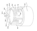
図13は、本実施の形態5の垂直軸型マグナス式風力発電機の正面から視た断面構成図である。図13に示すように、本実施の形態5の垂直軸型マグナス式風力発電機には、風車部622の中央に縦軸623が設けられている。この縦軸623は、台座1に固定されており、風車部622は、縦軸623に対して回転自在に構成されている。そのため、本実施の形態5では、縦軸623に対して回転自在に構成された下側支持部材654と上側支持部材656が設けられている。この上側支持部材656には、上側の支持軸609を支持する軸受け部656bが形成されており、下側支持部材654は、その天井部654sに設けられた軸受け部654bで、下側の支持軸6を支持する。
FIG. 13 is a cross-sectional configuration diagram viewed from the front of the vertical axis Magnus type wind power generator according to the fifth embodiment. As shown in FIG. 13, the vertical axis Magnus type wind power generator according to the fifth embodiment is provided with a vertical axis 623 in the center of the windmill unit 622. The vertical axis 623 is fixed to the base 1, and the windmill unit 622 is configured to be rotatable with respect to the vertical axis 623. Therefore, in the fifth embodiment, a lower support member 654 and an upper support member 656 configured to be rotatable with respect to the vertical axis 623 are provided. The upper support member 656 is formed with a bearing portion 656b that supports the upper support shaft 609, and the lower support member 654 is a bearing portion 654b provided on the ceiling portion 654s, and a lower support shaft. 6 is supported.
又、発電機624は、下側支持部材654の上側に配置されている。この発電機624は、中央に設けられた固定子624aと、その周囲に設けられた回転子624bを有しているアウターロータ型の発電機である。固定子624aは、縦軸623の一部によって構成されており、回転子624bは下側支持部材614上に固定されている。
Further, the generator 624 is disposed on the upper side of the lower support member 654. The generator 624 is an outer rotor type generator having a stator 624a provided at the center and a rotor 624b provided around the stator 624a. The stator 624a is constituted by a part of the longitudinal axis 623, and the rotor 624b is fixed on the lower support member 614.
すなわち、本実施の形態の発電機では、風車部622が回転すると、固定されている縦軸623に対して、風車部622の回転とともに、発電機624の回転子624bが回転し、発電が行われる。
That is, in the generator according to the present embodiment, when the windmill unit 622 rotates, the rotor 624b of the generator 624 rotates with the rotation of the windmill unit 622 with respect to the fixed vertical axis 623 to generate power. Is called.
このように、アウターロータ型の発電機が用いられても良い。
Thus, an outer rotor type generator may be used.
尚、図13では、自転制御部12と、回転数検出部16と、切替部14と、発電機制御部17、風速計15、温度計18、及び感雪計19は省略しているが、本実施の形態の場合、回転数検出部は、回転子624bの回転を検出し、発電機制御部は、切替部14を動作させることにより、回転子624bを動かすことになる。又、風が弱い又は無風のため、風車部622が回転していない場合には、実施の形態1と同様の制御が行われるが、発電機回転軸3a、すなわち回転子100を回転させる代わりに、本実施の形態では、回転子624bを回転させることになる。
In FIG. 13, the rotation control unit 12, the rotation speed detection unit 16, the switching unit 14, the generator control unit 17, the anemometer 15, the thermometer 18, and the snow gauge 19 are omitted. In the case of the present embodiment, the rotation speed detection unit detects the rotation of the rotor 624b, and the generator control unit moves the rotor 624b by operating the switching unit 14. Further, when the wind turbine unit 622 is not rotating because the wind is weak or no wind, the same control as in the first embodiment is performed, but instead of rotating the generator rotating shaft 3a, that is, the rotor 100. In this embodiment, the rotor 624b is rotated.
(実施の形態6)
次に、本発明にかかる実施の形態6における垂直軸型マグナス式風力発電機について説明する。本実施の形態6における垂直軸型マグナス式風力発電機は、実施の形態1と基本的な構成は同じであるが、制御方法が異なっている。そのため、本相違点を中心に説明する。尚、実施の形態1と同様の構成については同一の符号が付されている。
(Embodiment 6)
Next, a vertical axis Magnus type wind power generator according to Embodiment 6 of the present invention will be described. The vertical axis Magnus type wind power generator in the sixth embodiment has the same basic configuration as that of the first embodiment, but is different in control method. Therefore, this difference will be mainly described. In addition, the same code | symbol is attached | subjected about the structure similar to Embodiment 1. FIG.
図14は、本実施の形態6の垂直軸型マグナス式風力発電機の正面から視た断面構成図である。
FIG. 14 is a cross-sectional configuration diagram seen from the front of the vertical axis Magnus type wind power generator according to the sixth embodiment.
図14に示すように、本実施の形態6では、風速計15が設けられておらず、回転数検出部16で検出された回転数に基づいて、発電機回転軸3aが停止している時間を検出する停止時間検出部13が設けられている。
As shown in FIG. 14, in the sixth embodiment, the anemometer 15 is not provided, and the time when the generator rotating shaft 3 a is stopped based on the rotation speed detected by the rotation speed detector 16. A stop time detector 13 is provided for detecting.
次に、風が弱い又は無風のため、発電機回転軸3aが回転していない状態における本実施の形態6の制御について説明する。
Next, the control of the sixth embodiment in a state where the generator rotating shaft 3a is not rotating due to weak wind or no wind will be described.
停止時間検出部13によって検出された、発電機回転軸3aの停止時間が所定時間以上である場合には、発電機制御部17は、一定時間毎に切替部14を動作し、発電機3を動力源に切替え、発電機回転軸3aを所定時間の間、第1の所定の回転速度で駆動させるように制御を行う。尚、このとき、自転制御部12によって、バレル5を第1の所定の回転速度以上の速度で自転させる制御が行われる方がより好ましい。
When the stop time of the generator rotating shaft 3a detected by the stop time detection unit 13 is equal to or longer than a predetermined time, the generator control unit 17 operates the switching unit 14 at regular time intervals to change the generator 3 Switching to the power source is performed so that the generator rotating shaft 3a is driven at a first predetermined rotational speed for a predetermined time. At this time, it is more preferable that the rotation control unit 12 controls the barrel 5 to rotate at a speed equal to or higher than the first predetermined rotation speed.
このように制御することによって、弱い風が吹いた場合であっても、風車部2が回転しやすくなり、発電状態に移行出来る可能性が高まる。
By controlling in this way, even if a weak wind blows, the windmill unit 2 is likely to rotate, and the possibility of being able to shift to a power generation state is increased.
次に、積雪・凍結防止の際の制御について説明する。
Next, the control for preventing snow accumulation and freezing will be described.
感雪計19によって、積雪が感知され、且つ回転数検出部16によって発電機回転軸3aの回転が検知された場合、すなわち発電運転を行っている場合には、自転制御部12は、一定時間毎に、バレル5を第2の所定の回転速度以上の回転速度で、予め決められた時間、自転させるように制御を行う。ここで、第2の所定の回転速度は、発電時の制御による回転数よりも速い回転速度である。
When snow is detected by the snow meter 19 and the rotation of the generator rotating shaft 3a is detected by the rotation speed detection unit 16, that is, when the power generation operation is performed, the rotation control unit 12 Each time, the barrel 5 is controlled to rotate at a rotation speed equal to or higher than a second predetermined rotation speed for a predetermined time. Here, the second predetermined rotation speed is a rotation speed faster than the rotation speed by the control during power generation.
このように、一定時間毎に速い回転速度で、予め決められた時間、高速で回転させることにより、バレル5上の積雪を落下させることが出来る。
Thus, the snow on the barrel 5 can be dropped by rotating at a high speed for a predetermined time at a high rotational speed at regular intervals.
感雪計19によって、積雪が感知され、且つ発電機回転軸3aの停止時間が所定時間以上である場合には、発電機制御部17は、一定時間毎に切替部14を動作し、発電機3を動力源に切替え、発電機回転軸3aを所定時間の間、第2の回転速度で駆動させるように制御を行う。尚、このとき、自転制御部12は、一定時間毎に、バレル5を第2の所定の回転速度以上の回転速度で、予め決められた時間、自転させるように制御を行う。
When snow is detected by the snow gauge 19 and the stop time of the generator rotating shaft 3a is longer than a predetermined time, the generator control unit 17 operates the switching unit 14 at regular intervals, and the generator 3 is switched to a power source, and the generator rotating shaft 3a is controlled to be driven at the second rotational speed for a predetermined time. At this time, the rotation control unit 12 performs control so that the barrel 5 rotates at a rotation speed equal to or higher than the second predetermined rotation speed for a predetermined time at regular time intervals.
また、温度計18によって、凍結の可能性のある温度であることが検知され、且つ発電機回転軸3aの停止時間が所定時間以上である場合には、発電機制御部17は、一定時間毎に切替部14を動作し、発電機3を動力源に切替え、発電機回転軸3aを所定時間の間、第2の所定の回転速度で駆動させるように制御を行う。尚、このとき、自転制御部12によって、バレル5を第3の所定の回転速度以下の速度で自転させる制御が行われる。
When the thermometer 18 detects that the temperature is likely to freeze and the stop time of the generator rotating shaft 3a is equal to or longer than a predetermined time, the generator controller 17 Then, the switching unit 14 is operated to switch the generator 3 to the power source and control the generator rotating shaft 3a to be driven at the second predetermined rotation speed for a predetermined time. At this time, the rotation control unit 12 performs control to rotate the barrel 5 at a speed equal to or lower than a third predetermined rotation speed.
上記発電機回転軸3aの第2の所定の回転速度は、低速であり、バレル5の第3の所定の回転速度は、第2の所定の回転速度よりも遅い低速である。
The second predetermined rotation speed of the generator rotating shaft 3a is a low speed, and the third predetermined rotation speed of the barrel 5 is a lower speed than the second predetermined rotation speed.
このように発電が行われていない時でも、発電機回転軸3a及びバレル5を低速で回転させることにより、凍結を防止することが出来る。
Even when power generation is not performed in this manner, freezing can be prevented by rotating the generator rotating shaft 3a and the barrel 5 at a low speed.
尚、実施の形態1~6では、温度計18及び感雪計19が設けられていたが、積雪や凍結がない地域では設けられていなくてもよい。
In the first to sixth embodiments, the thermometer 18 and the snow sensitivity meter 19 are provided, but may not be provided in an area where there is no snow accumulation or freezing.
又、手動式のスイッチ又は遠隔操作により、積雪防止又は凍結防止のための動作のオンオフを切り替えても良い。
Also, the operation for preventing snow accumulation or preventing freezing may be switched on and off by a manual switch or remote control.
又、実施の形態1、3、6では、支持部材4の上側の全体がカバー部材11によって覆われていたが、図15に示す実施の形態1の変形例のように、少なくともバレル組50の下方の第1ギア7、第2ギア及びモータ9のみを覆うようにカバー部材111が設けられていても良い。
In the first, third, and sixth embodiments, the entire upper side of the support member 4 is covered with the cover member 11. However, as in the modification of the first embodiment shown in FIG. A cover member 111 may be provided so as to cover only the lower first gear 7, second gear and motor 9.
又、本実施の形態6では、インナーロータ型の発電機3を用いているため、発電機回転軸3a、すなわち回転子100の停止時間を検出しているが、実施の形態5のようにアウターロータ型の発電機624を用いた場合には、回転子624bの停止時間を検出して、上記と同様の制御を行えばよい。
In the sixth embodiment, since the inner rotor type generator 3 is used, the stop time of the generator rotating shaft 3a, that is, the rotor 100 is detected. When the rotor type generator 624 is used, the same control as described above may be performed by detecting the stop time of the rotor 624b.
(実施の形態7)
次に、本発明にかかる実施の形態7における垂直軸型マグナス式風力発電機について説明する。本実施の形態7における垂直軸型マグナス式風力発電機は、実施の形態1と基本的な構成は同じであるが、支持部材の形状が異なり、伸縮可能に構成されている点が異なる。そのため、本相違点を中心に説明する。尚、実施の形態1と同様の構成については同一の符号が付されている。
(Embodiment 7)
Next, a vertical axis type Magnus wind turbine generator according to a seventh embodiment of the present invention will be described. The vertical axis Magnus type wind power generator according to the seventh embodiment has the same basic configuration as that of the first embodiment, but is different in that the shape of the support member is different and the structure is extendable. Therefore, this difference will be mainly described. In addition, the same code | symbol is attached | subjected about the structure similar to Embodiment 1. FIG.
図16は、本実施の形態7の垂直軸型マグナス式風力発電機の斜視構成図である。図16に示すように、本実施の形態7の支持部材40は、平面視において十字形状であり、発電機回転軸3aが固定されている中央部41から、四方に突出するようにアーム部42が伸びており、その先端にバレル組50(バレル5a、5b)が配置されている。そして、隣り合うアーム部42が形成する角度は直角になっている。
FIG. 16 is a perspective configuration diagram of the vertical axis Magnus type wind power generator according to the seventh embodiment. As shown in FIG. 16, the support member 40 according to the seventh embodiment has a cross shape in plan view, and the arm portion 42 protrudes in four directions from the central portion 41 to which the generator rotating shaft 3 a is fixed. The barrel set 50 ( barrels 5a and 5b) is disposed at the tip thereof. And the angle which the adjacent arm part 42 forms is a right angle.
又、アーム部42の発電機回転軸3aとバレル組50の間には、伸縮部43が形成されている。図17は、伸縮部43近傍の拡大構成図である。尚、図17では、伸縮部43が伸びた状態が示されている。
Further, a telescopic part 43 is formed between the generator rotating shaft 3 a of the arm part 42 and the barrel set 50. FIG. 17 is an enlarged configuration diagram in the vicinity of the stretchable portion 43. Note that FIG. 17 shows a state in which the stretchable portion 43 is extended.
図17に示すように、伸縮部43は、複数個の枠状部材44を有している。本実施の形態では、枠状部材の数を4個とし、アーム部42の先端42a側から順に44a、44b、44c、44dと符号を付す。この枠状部材44a、44b、44c、44dは、順に大きさが大きくなっており、枠状部材44aは、隣の枠状部材44bに挿入され、枠状部材44bは、隣の枠状部材44cに挿入され、枠状部材44cは、隣の枠状部材44dに挿入されるように構成されている。又、枠状部材44aを、枠状部材44bから引き抜いた場合でも、枠状部材44aの中央部41側の縁部Sが、枠状部材44bの先端42a側の縁部Tに係止されるように形成されており、離間しないように構成されている。これは、他の枠状部材の間でも同様である。
As shown in FIG. 17, the stretchable part 43 has a plurality of frame-like members 44. In the present embodiment, the number of frame-like members is four, and reference numerals 44a, 44b, 44c, and 44d are attached in order from the tip 42a side of the arm portion 42. The frame-shaped members 44a, 44b, 44c, and 44d are sequentially increased in size. The frame-shaped member 44a is inserted into the adjacent frame-shaped member 44b, and the frame-shaped member 44b is inserted into the adjacent frame-shaped member 44c. The frame-shaped member 44c is configured to be inserted into the adjacent frame-shaped member 44d. Even when the frame-shaped member 44a is pulled out from the frame-shaped member 44b, the edge S on the central portion 41 side of the frame-shaped member 44a is locked to the edge T on the front end 42a side of the frame-shaped member 44b. It is formed so that it is not separated. The same applies to other frame-like members.
そして、枠状部材44aは、アーム部42の伸縮部43よりも先端42a側の外側部分45に固定されており、枠状部材44dは、アーム部42の伸縮部43よりも中央部41側の内側部分46に固定されている。これら外側部分45及び内側部分46には、それぞれの内部に突起部45a、46aが形成されており、突起部45a、46aにバネ部材47が固定されている。バネ部材47は、その両端がそれぞれ突起部45a、46aに固定されており、伸縮部43が縮むように付勢している。
The frame-shaped member 44a is fixed to the outer portion 45 closer to the tip 42a than the expansion / contraction part 43 of the arm part 42, and the frame-shaped member 44d is closer to the central part 41 than the expansion / contraction part 43 of the arm part 42. It is fixed to the inner part 46. The outer portion 45 and the inner portion 46 have projections 45a and 46a formed therein, and a spring member 47 is fixed to the projections 45a and 46a. Both ends of the spring member 47 are fixed to the protrusions 45a and 46a, respectively, and are biased so that the expansion / contraction part 43 contracts.
又、外側部分45を水平に保つために、外側部分45と内側部分46を連結する補強部材56が、アーム部42の内部に設けられている。この補強部材56は板状の部材であり、一端は、外側部分45に固定されている。又、他端には、長孔56aが形成されており、その長孔56aに嵌って内側部分46に固定されているピン57が設けられている。このピン57は、長孔56aから抜けないように、上端が大きく形成されている。すなわち、補強部材56はスライド可能に構成されている。
Also, in order to keep the outer portion 45 horizontal, a reinforcing member 56 that connects the outer portion 45 and the inner portion 46 is provided inside the arm portion 42. The reinforcing member 56 is a plate-like member, and one end is fixed to the outer portion 45. Further, a long hole 56a is formed at the other end, and a pin 57 that is fitted to the long hole 56a and fixed to the inner portion 46 is provided. The pin 57 has a large upper end so as not to come out of the long hole 56a. That is, the reinforcing member 56 is configured to be slidable.
又、アーム部42の外側部分45の上側には、実施の形態1において説明した第1ギア7、第2ギア8、モータ9、駆動ギア10等を覆うカバー部材48が設けられている。そして、その上にバレル5a、5bが配置されている。
Further, a cover member 48 that covers the first gear 7, the second gear 8, the motor 9, the drive gear 10, and the like described in the first embodiment is provided above the outer portion 45 of the arm portion 42. And the barrels 5a and 5b are arrange | positioned on it.
次に、本実施の形態7の垂直軸型マグナス式風力発電機の動作について説明する。
Next, the operation of the vertical axis type Magnus type wind power generator according to the seventh embodiment will be described.
発電機回転軸3aが回転する前の状態では、図18に示すように、バネ部材47の付勢力によって、先端42a側の枠状部材44が、その隣の中央側の枠状部材44に嵌り、縮んだ状態となっている。詳しく説明すると、枠状部材44aが枠状部材44bに嵌り、枠状部材44bが枠状部材44cに嵌り、枠状部材44cが枠状部材44dに嵌った状態となっている。
In the state before the generator rotating shaft 3a rotates, the frame-like member 44 on the tip 42a side is fitted into the frame-like member 44 on the adjacent central side by the biasing force of the spring member 47, as shown in FIG. It is in a contracted state. More specifically, the frame-like member 44a is fitted into the frame-like member 44b, the frame-like member 44b is fitted into the frame-like member 44c, and the frame-like member 44c is fitted into the frame-like member 44d.
そして、風によって風車部2が回転すると、バレル組50、外側部分45にかかる遠心力によって、バネ部材47の付勢力に対抗し、徐々に伸縮部43が伸びる(図17参照)。尚、補強部材56は外側部分45の外側への移動に伴ってスライドすることになる。
And when the windmill part 2 rotates with a wind, the expansion / contraction part 43 will be extended gradually with opposition to the urging | biasing force of the spring member 47 with the centrifugal force concerning the barrel assembly 50 and the outer part 45 (refer FIG. 17). The reinforcing member 56 slides as the outer portion 45 moves outward.
本実施の形態では、発電を開始する前の状態では、アーム部42が縮んだ状態となっているため、回転半径が小さく、弱い風速でも回転し、発電し易くなる。
In the present embodiment, since the arm portion 42 is in a contracted state before power generation is started, the rotation radius is small, and the motor rotates easily even at a weak wind speed, thereby facilitating power generation.
尚、本実施の形態7では、伸縮部43が4つの枠状部材で形成されていたが、これに限られるものではない。
In the seventh embodiment, the stretchable part 43 is formed by four frame-shaped members, but is not limited to this.
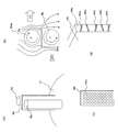
尚、上記実施の形態1~7のバレル5a、5bの間に、本発明の気流遮蔽手段の一例に対応する気流遮蔽板49が設けられていても良い。図19(a)は、実施の形態1を例に挙げて、バレル5aとバレル5bの間に設けられている気流遮蔽板49示す斜視構成図である。図19(b)は、バレル組50aのバレル5a、5bの自転と風向きによって生じるマグナス力の関係を示す図である。図4において説明したように、バレル5aのマグナス力(V1)とバレル5bに生じるマグナス力(V2)は、反対向きとなっているため、回転する力がバレル5bのマグナス力によって弱くなる。しかしながら、図19に示すように気流遮蔽板49を設けることによって、バレル5bに生じるマグナス力(V2)を弱く出来るため、回転する力が強くなり、よりエネルギー効率を向上することが出来る。これは、バレル組50が発電機回転軸3aを基準にして風下側に移動した場合も同様である。
An airflow shielding plate 49 corresponding to an example of the airflow shielding means of the present invention may be provided between the barrels 5a and 5b of the first to seventh embodiments. FIG. 19A is a perspective configuration diagram showing an airflow shielding plate 49 provided between the barrel 5a and the barrel 5b, taking Embodiment 1 as an example. FIG. 19B is a diagram illustrating the relationship between the rotation of the barrels 5a and 5b of the barrel set 50a and the Magnus force generated by the wind direction. As described in FIG. 4, since the Magnus force (V1) of the barrel 5a and the Magnus force (V2) generated in the barrel 5b are in opposite directions, the rotating force is weakened by the Magnus force of the barrel 5b. However, by providing the airflow shielding plate 49 as shown in FIG. 19, the Magnus force (V2) generated in the barrel 5b can be weakened, so that the rotating force becomes strong and the energy efficiency can be further improved. This is the same when the barrel set 50 moves to the leeward side with respect to the generator rotating shaft 3a.
尚、この気流遮蔽板49の表面には、気流を拡散・又は分散させるような形状が形成されている方がより好ましく、例えば、図19(c)に示すような凹部49aが形成されていればよい。
It is more preferable that the surface of the airflow shielding plate 49 is formed with a shape that diffuses or disperses the airflow. For example, a concave portion 49a as shown in FIG. That's fine.
更に、気流遮蔽板49の側端面49bに、気流を拡散又は分散させるような形状が形成されている方がより好ましい。例えば、図19(d)に示すような筋状の突部49cが形成されていればよい。複数の突部49cは、隣合う突部49cの間隔が大きくなる又は小さくなるように水平方向に対して斜めに形成されている。具体的には、図19(d)の最も上方の突部49cは、紙面手前よりも奥行き側が低くなるように斜めに形成されており、その下側の2番目の突部49cは、紙面手前よりも奥行き側が高くなるように斜めに形成されており、この2つの突部49cの間隔は、紙面奥行き方向にいくに従って小さくなっている。一方、3番目の突部49cは、紙面手前よりも奥行き側が低くなるように斜めに形成されており、2番目と3番目の2つの突部49cの間隔は、紙面奥行き方向にいくに従って大きくなっている。このように紙面奥行き方向にいくに従って幅が小さくなる形状と、幅が大きくなる形状が交互に形成されている。上記のように、本発明の気流遮蔽手段の一例として気流遮蔽板49について説明したが、板状でなくてもよい。
Furthermore, it is more preferable that the side end face 49b of the airflow shielding plate 49 is formed with a shape that diffuses or disperses the airflow. For example, a streak-like protrusion 49c as shown in FIG. The plurality of protrusions 49c are formed obliquely with respect to the horizontal direction so that the interval between adjacent protrusions 49c is increased or decreased. Specifically, the uppermost protrusion 49c in FIG. 19D is formed obliquely so that the depth side is lower than the front side of the sheet, and the second protrusion 49c on the lower side is the front side of the sheet. It is formed obliquely so that the depth side becomes higher than the distance, and the interval between the two protrusions 49c becomes smaller in the depth direction of the paper. On the other hand, the third protrusion 49c is formed obliquely so that the depth side is lower than the front side of the sheet, and the interval between the second and third two protrusions 49c increases as the depth of the sheet increases. ing. In this way, a shape with a smaller width and a shape with a larger width are formed alternately in the depth direction of the drawing. As described above, although the airflow shielding plate 49 has been described as an example of the airflow shielding means of the present invention, the airflow shielding plate 49 may not be plate-shaped.
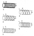
又、上記実施の形態1~7のバレル5の表面に、図20(a)に示すようにディンプル状の凹み51を形成しても良い。又、図20(b)に示すように突起物52を形成しても良い。更に、図20(c)に示すように、バレル5の表面に支持軸6に対して平行なリブ53が形成されていてもよい。又、支持軸6に対して平行なリブに限らず、図20(d)に示すように、バレル5の表面に、支持軸6に対して垂直なリブ54が形成されていてもよい。又、図20(e)に示すように、螺旋状のリブ55が形成されていても良い。
Further, a dimple-like recess 51 may be formed on the surface of the barrel 5 of the first to seventh embodiments as shown in FIG. Moreover, you may form the protrusion 52 as shown in FIG.20 (b). Further, as shown in FIG. 20C, ribs 53 parallel to the support shaft 6 may be formed on the surface of the barrel 5. Further, not only the rib parallel to the support shaft 6 but also a rib 54 perpendicular to the support shaft 6 may be formed on the surface of the barrel 5 as shown in FIG. Moreover, as shown in FIG.20 (e), the helical rib 55 may be formed.
これらのようにバレル5の表面を形成することによって、気流の流れが良くなり、少しの自転によって大きいマグナス力の効果を得ることができ、バレル5の回転騒音を小さくする効果も得られる。
By forming the surface of the barrel 5 as described above, the flow of the airflow is improved, and the effect of a large Magnus force can be obtained by a little rotation, and the effect of reducing the rotational noise of the barrel 5 can also be obtained.
又、実施の形態1~7のバレル5が、中空であっても良い。図21は、このような構成のバレル105の構成を示す図である。図21に示すバレル105は中空であり、その中心に支持軸106が配置されている。この支持軸106とバレル105は、支持アーム107によって連結されている。
Further, the barrel 5 of the first to seventh embodiments may be hollow. FIG. 21 is a diagram showing a configuration of the barrel 105 having such a configuration. A barrel 105 shown in FIG. 21 is hollow, and a support shaft 106 is disposed at the center thereof. The support shaft 106 and the barrel 105 are connected by a support arm 107.
このように中空に構成することにより、バレル5の軽量化を図ることが出来、自転にかかるトルクを小さくすることが出来る。
</ RTI> By thus forming a hollow structure, the weight of the barrel 5 can be reduced, and the torque required for rotation can be reduced.
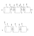
又、上記実施の形態1~7では、バレル5は、1つの部材であるが、長さが長い場合等には、持ち運びを考慮して分割して構成されていても良い。図22は、このようなバレル630の分解斜視構成図である。図22に示すように、バレル630は、上から順に配置された2つの円筒部631、632と、円筒部631の上側に配置される上支持軸部633と、円筒部631と円筒部632の間を接続する接続部634、円筒部632の下側に配置される下支持軸部635とを有している。これら円筒部631、632は、中空であり、上下に4箇所ずつネジ用の貫通孔631a、631b、632a、632bが形成されている。
In Embodiments 1 to 7, the barrel 5 is a single member. However, when the length is long, etc., the barrel 5 may be divided in consideration of carrying. FIG. 22 is an exploded perspective view of such a barrel 630. As shown in FIG. 22, the barrel 630 includes two cylindrical parts 631 and 632 arranged in order from the top, an upper support shaft part 633 arranged on the upper side of the cylindrical part 631, and the cylindrical part 631 and the cylindrical part 632. It has a connecting portion 634 that connects between them, and a lower support shaft portion 635 that is disposed below the cylindrical portion 632. These cylindrical portions 631 and 632 are hollow, and screw through- holes 631a, 631b, 632a, and 632b are formed at four positions in the vertical direction.
又、上支持軸部633は、上支持軸633aと、円筒部631に嵌る嵌合部633bと、上支持軸633aと嵌合部633bの間に形成された円柱部633cとを有しており、嵌合部633bにはネジ孔633dが4つ形成されている。接続部634は、円筒部631の内側に嵌る嵌合部634aと、円筒部632の内側に嵌る嵌合部634bと、嵌合部634aと嵌合部634bの間に形成された円柱部634cとを有している。そして、嵌合部634aには、ネジ孔634dが4つ形成されており、嵌合部634bには、ネジ孔634eが4つ形成されている。下支持軸部635は、下支持軸635aと、円筒部632の内側に嵌る嵌合部635bと、下支持軸635aと嵌合部635bの間に設けられた円柱部635cとを有しており、嵌合部635bにはネジ孔635dが4つ形成されている。これら円筒部631、632、及び円柱部633c、634c、635cは、全て同じ径である。尚、本発明のバレル部分の一例は、円筒部631、632、又は円柱部633c、634c、635cに対応する。
The upper support shaft portion 633 includes an upper support shaft 633a, a fitting portion 633b that fits into the cylindrical portion 631, and a columnar portion 633c formed between the upper support shaft 633a and the fitting portion 633b. The fitting portion 633b has four screw holes 633d. The connecting portion 634 includes a fitting portion 634a that fits inside the cylindrical portion 631, a fitting portion 634b that fits inside the cylindrical portion 632, and a columnar portion 634c formed between the fitting portion 634a and the fitting portion 634b. have. The fitting portion 634a has four screw holes 634d, and the fitting portion 634b has four screw holes 634e. The lower support shaft portion 635 includes a lower support shaft 635a, a fitting portion 635b that fits inside the cylindrical portion 632, and a columnar portion 635c provided between the lower support shaft 635a and the fitting portion 635b. The fitting portion 635b has four screw holes 635d. These cylindrical portions 631 and 632 and column portions 633c, 634c, and 635c all have the same diameter. In addition, an example of the barrel part of this invention respond | corresponds to the cylindrical parts 631 and 632, or the column parts 633c, 634c, and 635c.
そして、上支持軸部633の嵌合部633bと接続部634の嵌合部634aを円筒部631の内側に嵌め込み、接続部634の嵌合部634bと下支持軸部635の嵌合部635bを円筒部632の内側に嵌め込み、ネジ孔633dと貫通孔631aを合わせ、ネジ孔634dと貫通孔631bを合わせ、ネジ孔634eと貫通孔632aを合わせ、ネジ孔635dと貫通孔632bを合わせて、それぞれをネジ636で止めることにより、バレル630が組み立てられる。尚、上支持軸633aが、図7のバレル5の上側の支持軸609に対応し、下支持軸635aが図7のバレル5の支持軸6に対応する。
Then, the fitting portion 633b of the upper support shaft portion 633 and the fitting portion 634a of the connection portion 634 are fitted inside the cylindrical portion 631, and the fitting portion 634b of the connection portion 634 and the fitting portion 635b of the lower support shaft portion 635 are fitted. Fit inside the cylindrical portion 632, match the screw hole 633d and the through hole 631a, match the screw hole 634d and the through hole 631b, match the screw hole 634e and the through hole 632a, match the screw hole 635d and the through hole 632b, respectively. Is assembled with a screw 636 to assemble the barrel 630. The upper support shaft 633a corresponds to the upper support shaft 609 of the barrel 5 in FIG. 7, and the lower support shaft 635a corresponds to the support shaft 6 of the barrel 5 in FIG.
尚、図22では、上記ネジ用の貫通孔、上記ネジ孔、及び上記ネジの裏側2箇所は省略している。
In FIG. 22, the through hole for the screw, the screw hole, and two locations on the back side of the screw are omitted.
又、分割可能なバレルの一例として、図23(a)、図23(b)に示す構成が用いられても良い。図23(a)は、このようなバレル205の斜視構成図である。図23(b)は、バレル205を分割した状態を示す斜視構成図である。図23(a)、(b)に示すように、バレル205は、上から順に配置された複数のバレル部251、252、253によって構成されている。最上部に位置するバレル部251は、その下側に連結軸61を有しており、中央に位置するバレル部252は、その上側に設けられた連結軸62と、その下側に設けられた連結軸63とを有している。最下部に位置するバレル部253は、その上側に設けられた連結軸64と、その下側に設けられた支持軸65とを有している。そして、連結軸61、62、63、64は中空であり、それぞれ貫通孔61a、62a、63a、64aが形成されている。
Further, as an example of the barrel that can be divided, the configuration shown in FIGS. 23A and 23B may be used. FIG. 23A is a perspective configuration diagram of such a barrel 205. FIG. 23B is a perspective configuration diagram illustrating a state where the barrel 205 is divided. As shown in FIGS. 23A and 23B, the barrel 205 includes a plurality of barrel portions 251, 252, and 253 arranged in order from the top. The barrel portion 251 located at the uppermost portion has a connecting shaft 61 on the lower side thereof, and the barrel portion 252 located at the center is provided with a connecting shaft 62 provided on the upper side thereof and on the lower side thereof. And a connecting shaft 63. The barrel portion 253 located at the lowermost portion has a connecting shaft 64 provided on the upper side and a support shaft 65 provided on the lower side. The connecting shafts 61, 62, 63, 64 are hollow, and through holes 61a, 62a, 63a, 64a are formed, respectively.
図23(a)、(b)に示すように、バレル部251の連結軸61が、バレル部252の連結軸62の内側に嵌められ、貫通孔61aと貫通孔62aの位置を合わせた状態で、ピン254を貫通孔61a、62aに差し込むことによって、バレル部251とバレル部252は固定される。同様に、バレル部252の連結軸63が、バレル部253の連結軸64の内側に嵌められ、貫通孔63aと貫通孔64aの位置を合わせた状態で、ピン254を貫通孔63a、64aに差し込むことによって、バレル部252とバレル部253は固定される。尚、第1ギア7、第2ギア8は、支持軸65に配置されることになる。
As shown in FIGS. 23A and 23B, the connecting shaft 61 of the barrel portion 251 is fitted inside the connecting shaft 62 of the barrel portion 252, and the positions of the through hole 61a and the through hole 62a are aligned. The barrel 251 and the barrel 252 are fixed by inserting the pin 254 into the through holes 61a and 62a. Similarly, the connecting shaft 63 of the barrel portion 252 is fitted inside the connecting shaft 64 of the barrel portion 253, and the pin 254 is inserted into the through holes 63a and 64a with the positions of the through hole 63a and the through hole 64a being aligned. Thus, the barrel portion 252 and the barrel portion 253 are fixed. The first gear 7 and the second gear 8 are arranged on the support shaft 65.
このように構成することによって、持ち運びに便利となる。尚、図22では、上支持軸633aと下支持軸635aが設けられており、図23では、下側の支持軸65が設けられているが、上側の支持軸のみが設けられた構成であってもよい(図示省略)。又、分割していないバレル5についても、上側の支持軸609のみで支持された構成であってもよい(図示省略)。
This configuration makes it convenient for carrying around. In FIG. 22, an upper support shaft 633a and a lower support shaft 635a are provided. In FIG. 23, a lower support shaft 65 is provided, but only the upper support shaft is provided. (Not shown). Also, the barrel 5 that is not divided may be supported only by the upper support shaft 609 (not shown).
又、実施の形態1~6では、円板形状の支持部材が用いられているが、フライホイール効果を発揮するように構成されていてもよい。具体的には、質量が重くなるように金属等で形成することが出来る。又、図24(a)の支持部材204に示すように、中央部分204aと周縁部分204bの材料を変更し、周縁部分204bの材料として、中央部分204aの材料よりも単位体積あたりの質量が重いものを用いればよい。更に、例えば、図24(b)に示すように、下側支持部材604(図6参照)の下側全体に錘605を配置してもよいし、図24(c)に示すように、下側支持部材604の下側の周囲に錘608を配置しても良い。
In the first to sixth embodiments, a disk-shaped support member is used, but it may be configured to exhibit a flywheel effect. Specifically, it can be formed of metal or the like so as to increase the mass. Further, as shown in the support member 204 in FIG. 24A, the material of the central portion 204a and the peripheral portion 204b is changed, and the mass per unit volume is heavier than the material of the central portion 204a as the material of the peripheral portion 204b. What is necessary is just to use. Further, for example, as shown in FIG. 24B, a weight 605 may be disposed on the entire lower side of the lower support member 604 (see FIG. 6), or as shown in FIG. A weight 608 may be disposed around the lower side of the side support member 604.
又、上記実施の形態7の支持部材40に対してもフライホイール効果を持たせるため、外側部分45の材料を、中央部41及び内側部分46の材料よりも単位体積あたりの質量が重いものを用いてもよい。
Further, in order to give the flywheel effect to the support member 40 of the seventh embodiment, the material of the outer part 45 is heavier than the material of the central part 41 and the inner part 46. It may be used.
又、図8の上記実施の形態2の変形例で用いられているような十字形状の支持部材400が、図25(a)に示されている。この支持部材400は、平面視において十字形状であり、発電機回転軸3a及び縦軸603が固定される中央部401と、中央部401から四方に突出するように形成されたアーム部402とを有している。このようなアーム部402の先端402aの近傍の材料を、他の部分の材料よりも単位体積あたりの質量が重いものを用いることによって、フライホイール効果を発揮させることが出来る。
Further, a cross-shaped support member 400 used in the modification of the second embodiment shown in FIG. 8 is shown in FIG. The support member 400 has a cross shape in plan view, and includes a central portion 401 to which the generator rotating shaft 3a and the vertical axis 603 are fixed, and an arm portion 402 formed so as to protrude in four directions from the central portion 401. Have. By using such a material in the vicinity of the tip 402a of the arm portion 402 that has a higher mass per unit volume than the material of other portions, the flywheel effect can be exhibited.
又、先端402aの近傍の材料を変えなくても、図25(b)に示すように、アーム部402の先端402aを環状に繋ぐ環状部材402bを形成することによりフライホイール効果を持たせることが出来る。
Further, even if the material in the vicinity of the tip 402a is not changed, as shown in FIG. 25B, the flywheel effect can be provided by forming the annular member 402b that connects the tip 402a of the arm portion 402 in an annular shape. I can do it.
又、上記実施の形態1~7では、4つのバレル組50が設けられていたが、3つ以下、若しくは5つ以上であっても良い。尚、このとき、複数のバレル組50は、平面視において発電機回転軸3aを中心にして等間隔に配置されている方が好ましい。このように発電機回転軸3aを中心にして等間隔に放射状に配設することで発電機回転軸3aに生じる変動加重を平準化させることができる。又、バレル組50の数を適切に配置することにより、発電機回転軸の回転トルクを増大することが出来る。
In the first to seventh embodiments, the four barrel sets 50 are provided. However, the number may be three or less, or five or more. At this time, it is preferable that the plurality of barrel sets 50 be arranged at equal intervals around the generator rotation shaft 3a in plan view. In this way, by arranging the generator rotating shaft 3a radially at equal intervals around the generator rotating shaft 3a, the fluctuation weight generated in the generator rotating shaft 3a can be leveled. Moreover, the rotational torque of the generator rotating shaft can be increased by appropriately arranging the number of the barrel groups 50.
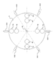
例えば、バレル組が3つの場合は、図26に示すように、隣のバレル組50と発電機回転軸3aの形成する角が略120度ずつとなるように配置する方が好ましい。尚、発電機回転軸3aを中心にして等間隔に配置されている方が変動加重の標準化の観点からは好ましいが、1つのバレル組50のみが配置されていても良い。1組だけ設けられていても良い。
For example, when there are three barrel groups, as shown in FIG. 26, it is preferable to arrange the adjacent barrel groups 50 and the generator rotating shaft 3a so that the angle formed by each is approximately 120 degrees. In addition, although it is preferable from the viewpoint of standardization of variation weighting that the generator rotation shaft 3a is arranged at equal intervals, only one barrel set 50 may be arranged. Only one set may be provided.
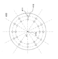
又、実施の形態1~6の円板形状の支持部材に、支持軸6を配置することが可能な軸受部4bが複数形成され、選択的にバレル5を配置する構成としても良い。図27は、支持部材410の平面構成図である。支持部材410には、その中心410aで発電機回転軸3aと固定されており、外側のバレル5の支持軸6を回転可能に配置する軸受部411と、内側のバレル5の支持軸6を回転可能に配置する軸受部412が設けられている。そして、図27に示す支持部材410では、軸受部411と軸受部412の組が、12組形成されている。又、隣り合う軸受部412、411の組と中心410aを結ぶ線によって形成される角度(図中α参照)は、全て等しくなっている。このように形成された支持部材410を用いることによって、バレル組50を1個、2個、3個、4個、6個、12個用いるように選択することが出来る。尚、2個、3個、4個、6個の場合、各バレル組50は、中心410aを中心として等間隔に配置する方が好ましい。尚、実施の形態1の構成の場合、カバー部材11についても内側の支持軸6と外側の支持軸6を一組として、12組、計24個の支持軸6が貫通する孔が形成されている。
In addition, a plurality of bearing portions 4b on which the support shaft 6 can be disposed are formed on the disk-shaped support members of the first to sixth embodiments, and the barrel 5 may be selectively disposed. FIG. 27 is a plan configuration diagram of the support member 410. The support member 410 is fixed to the generator rotating shaft 3a at the center 410a, and the bearing portion 411 that rotatably arranges the support shaft 6 of the outer barrel 5 and the support shaft 6 of the inner barrel 5 rotate. A bearing portion 412 that can be arranged is provided. In the support member 410 shown in FIG. 27, 12 sets of the bearing portion 411 and the bearing portion 412 are formed. Further, the angles (see α in the figure) formed by the line connecting the pair of adjacent bearing portions 412 and 411 and the center 410a are all equal. By using the support member 410 formed in this manner, it is possible to select one, two, three, four, six, or twelve barrel sets 50 to be used. In the case of two, three, four, and six, it is preferable that the barrel sets 50 are arranged at equal intervals around the center 410a. In the case of the configuration of the first embodiment, the cover member 11 is also formed with 12 holes, through which a total of 24 support shafts 6 pass, with the inner support shaft 6 and the outer support shaft 6 as one set. Yes.
このように複数の軸受部を形成することによって、部品の共通化を図ることが可能となりコストダウン出来、更に工場出荷後、設置後でもバレル組の数を増減することが出来る。
By forming a plurality of bearings in this way, it is possible to share parts and reduce costs, and the number of barrel groups can be increased or decreased after factory shipment and after installation.
又、図28に示すように、風車部を覆うように支持する枠構造が設けられていても良い。図28は、図6に示した実施の形態2の構成に、枠構造500が追加された構成を示す斜視構成図である。
In addition, as shown in FIG. 28, a frame structure that supports the windmill portion may be provided. FIG. 28 is a perspective configuration diagram showing a configuration in which a frame structure 500 is added to the configuration of the second embodiment shown in FIG.
図28に示すように、縦軸603が、上側支持部材606から突出しており、縦軸603の上端を回転可能に支持する上枠部材501と、上枠部材501と台座1とを連結する3つの側枠部503とを有している。上枠部材501は、縦軸603が配置される中央部501aと、中央部501aから側枠部503へと伸びるアーム部501bによって構成されている。このように構成することにより、風車部2はより安定して回転することが出来る。
As shown in FIG. 28, the vertical axis 603 protrudes from the upper support member 606, and the upper frame member 501 that rotatably supports the upper end of the vertical axis 603, the upper frame member 501, and the base 1 are connected to each other. Two side frame portions 503. The upper frame member 501 includes a central portion 501a where the vertical axis 603 is disposed, and an arm portion 501b extending from the central portion 501a to the side frame portion 503. By comprising in this way, the windmill part 2 can rotate more stably.
又、実施の形態2の構成の上側支持部材606と下側支持部材604を部分的に連結して、上側支持部材606を支える構成を採用しても良い。図29はそのような構成を示す図である。図29に示すように、上側支持部材606を支えるように、複数のバレル組の中間の位置において、下側支持部材604から縦枠660が設けられている。
Alternatively, a configuration in which the upper support member 606 and the lower support member 604 configured in the second embodiment are partially connected to support the upper support member 606 may be employed. FIG. 29 is a diagram showing such a configuration. As shown in FIG. 29, a vertical frame 660 is provided from the lower support member 604 at a position intermediate between the plurality of barrel sets so as to support the upper support member 606.
又、支持部材4の外側に整流板が設けられていても良い。図30は、4個のバレル組50が配置された垂直軸型マグナス式風力発電機の平面構成図である。図30に示すように、60度間隔で中心4a方向に向かって、支持部材4の外側に整流板502が設けられている。このように整流板502を配置することによって、風を風車部の縦軸に向かう方向に方向付けることで、風下側のバレルの遮蔽量が大きくなり、効率良く発電することが出来る。又、バレル組50と、中心4a(縦軸と一致)の間に整流板が設けられていても良い。
Further, a rectifying plate may be provided outside the support member 4. FIG. 30 is a plan view of a vertical axis Magnus type wind power generator in which four barrel sets 50 are arranged. As shown in FIG. 30, rectifying plates 502 are provided outside the support member 4 toward the center 4 a at intervals of 60 degrees. By arranging the current plate 502 in this way, the wind is directed in the direction toward the vertical axis of the wind turbine unit, so that the shielding amount of the barrel on the leeward side is increased, and power can be generated efficiently. Further, a rectifying plate may be provided between the barrel set 50 and the center 4a (coincident with the vertical axis).
尚、上記実施の形態のバレル組50では、バレル5bは、その中心がバレル5aと中心4a(縦軸と一致)を結ぶ線上に配置されているが、これに限られるものではなく、バレル5aと中心4aの間に配置されておればよい。但し、図31に示すように、バレル5bの少なくとも一部が領域S内に入っている方が好ましい。領域Sは、バレル5aと縦軸とを結ぶ直線と平行な、バレル5aの外周の2つの接線L、Mの間の領域である。
In the barrel set 50 of the above-described embodiment, the center of the barrel 5b is arranged on a line connecting the barrel 5a and the center 4a (coincident with the vertical axis), but the present invention is not limited to this. And the center 4a. However, it is preferable that at least a part of the barrel 5b is in the region S as shown in FIG. The region S is a region between two tangents L and M on the outer periphery of the barrel 5a, which is parallel to a straight line connecting the barrel 5a and the vertical axis.
又、バレル5bは、図32に示すように、その少なくとも一部が、バレル5aと中心4aの縦軸を結ぶ線上に載るように配置されている方がより好ましい。
Further, as shown in FIG. 32, the barrel 5b is preferably arranged so that at least a part thereof is placed on a line connecting the barrel 5a and the longitudinal axis of the center 4a.
尚、本発明の垂直軸型マグナス式風力発電機に太陽電池を備えても良い。
In addition, you may equip the vertical axis | shaft type Magnus type wind power generator of this invention with a solar cell.
又、本発明の垂直軸型マグナス式風力発電機の台座内部に、前記発電機の発生した電力や、前記太陽電池の発生した電力を貯蔵するための電力貯蔵手段を設けても良い。
Moreover, an electric power storage means for storing the electric power generated by the generator and the electric power generated by the solar cell may be provided inside the pedestal of the vertical axis Magnus type wind power generator of the present invention.
バレル5を自転させる電源、又は、発電機制御部17が、切替部14を制御し、発電機3を動力源として用いる際の電源として、前記電力貯蔵手段、商用電源などを適宜選択して用いることが出来る。
As the power source for rotating the barrel 5 or the generator control unit 17 controls the switching unit 14 and uses the generator 3 as a power source, the power storage means, the commercial power source and the like are appropriately selected and used. I can do it.
又、バレル5を自転させるモータ9は、ACモータに限らず、DCモータでもよい。DCモータを用い、且つ電力貯蔵手段として蓄電池を用いた場合、蓄電池に貯蔵された電力を直流のまま使用することが出来る。
The motor 9 that rotates the barrel 5 is not limited to an AC motor, and may be a DC motor. When a DC motor is used and a storage battery is used as the power storage means, the power stored in the storage battery can be used as a direct current.
又、風速計による風速が所定の風速よりも速くなった場合、又は回転子(発電機回転軸3a、回転子624b)の回転数が所定の回転数よりも大きくなった場合、風車部を停止するように制御が行われても良い。この停止には、電磁ブレーキなどを用いればよい。
In addition, when the wind speed measured by the anemometer becomes higher than a predetermined wind speed, or when the rotational speed of the rotor (the generator rotating shaft 3a and the rotor 624b) becomes higher than the predetermined rotational speed, the wind turbine unit is stopped. Control may be performed as follows. An electromagnetic brake or the like may be used for this stop.
以上のように、本発明によれば、風向の影響を受けず、発電機回転軸の風上側と風下側どちらの領域においても、発電機回転軸に対して同一方向の回転トルクを発生するので、発電効率が高い。
As described above, according to the present invention, the rotational torque in the same direction is generated with respect to the generator rotation shaft in both the windward and leeward regions of the generator rotation shaft without being affected by the wind direction. , Power generation efficiency is high.
また、風速または発電機回転軸3aの回転数を計測し、それを基にバレル5の自転回転数を変化させることで、起動性が良好となり、また広い風速域において発電可能である。
Further, by measuring the wind speed or the rotational speed of the generator rotating shaft 3a and changing the rotational speed of the barrel 5 based on the measured speed, the startability is improved, and power can be generated in a wide wind speed range.
さらに、風力発電機の安全性に支障をきたすような強風時には、バレル5の自転を停止する事で、マグナス力は0となり、かつバレル形状は風圧を受けにくいため、発電機回転軸3aの過回転を防止して、安全に停止させることができる。
Furthermore, when the wind is strong enough to interfere with the safety of the wind power generator, the rotation of the barrel 5 is stopped, so that the Magnus force becomes zero and the barrel shape is less susceptible to wind pressure. It can be stopped safely by preventing rotation.
さらにまた、本発明の風力発電機は、バレルの自転回転数制御を個別かつ頻繁に行う必要がなく、また大型化したときの自転回転数制御に対するバレルの応答性低下が発電効率の低下を招きにくいので、大型化が容易である。
Furthermore, the wind power generator according to the present invention does not require individual and frequent control of the rotation speed of the barrel, and a decrease in the response of the barrel to the rotation speed control when the size is increased leads to a decrease in power generation efficiency. It is difficult to increase the size.
さらにまた、本発明の風力発電機は、水平軸型の風力発電機のような高いタワーを必要としないため、ビルや家屋などの屋上に設置可能となる。
Furthermore, since the wind power generator of the present invention does not require a high tower like a horizontal axis type wind power generator, it can be installed on the roof of a building or a house.
さらにまた、本発明の風力発電機は、発電部分を地上付近に設置でき、メンテナンスが容易である。
Furthermore, the wind power generator of the present invention can be installed near the ground, and maintenance is easy.
さらにまた、バレル形状のブレードは製造が容易な上、風向計測装置等が不要で構成がシンプルであるため、製造コストとメンテナンスコストを低くすることができる。
Furthermore, since the barrel-shaped blade is easy to manufacture and does not require a wind direction measuring device or the like and has a simple configuration, manufacturing costs and maintenance costs can be reduced.
よって、本発明により、風向の影響を受けず、発電効率が高く、起動性が良好で、広い風速域において発電可能であり、かつ強風に対する安全性が高く、また大型化が容易で、ビルや家屋などの屋上へ設置可能であり、さらに低コストで製造及び運用可能な風力発電機が提供できる。
Therefore, according to the present invention, it is not affected by the wind direction, has high power generation efficiency, good startability, can generate power in a wide wind speed range, has high safety against strong winds, is easy to increase in size, It is possible to provide a wind power generator that can be installed on a roof such as a house and can be manufactured and operated at a lower cost.