WO2013014848A1 - Générateur éolien magnus de type à axe vertical - Google Patents
Générateur éolien magnus de type à axe vertical Download PDFInfo
- Publication number
- WO2013014848A1 WO2013014848A1 PCT/JP2012/003762 JP2012003762W WO2013014848A1 WO 2013014848 A1 WO2013014848 A1 WO 2013014848A1 JP 2012003762 W JP2012003762 W JP 2012003762W WO 2013014848 A1 WO2013014848 A1 WO 2013014848A1
- Authority
- WO
- WIPO (PCT)
- Prior art keywords
- barrel
- vertical axis
- generator
- magnus
- wind power
- Prior art date
Links
- 238000010248 power generation Methods 0.000 abstract description 35
- 238000010586 diagram Methods 0.000 description 57
- 230000004048 modification Effects 0.000 description 16
- 238000012986 modification Methods 0.000 description 16
- NJPPVKZQTLUDBO-UHFFFAOYSA-N novaluron Chemical compound C1=C(Cl)C(OC(F)(F)C(OC(F)(F)F)F)=CC=C1NC(=O)NC(=O)C1=C(F)C=CC=C1F NJPPVKZQTLUDBO-UHFFFAOYSA-N 0.000 description 14
- 238000001514 detection method Methods 0.000 description 13
- 238000004519 manufacturing process Methods 0.000 description 9
- 230000007246 mechanism Effects 0.000 description 9
- 230000005540 biological transmission Effects 0.000 description 8
- 230000008602 contraction Effects 0.000 description 8
- 230000000694 effects Effects 0.000 description 8
- 239000000463 material Substances 0.000 description 8
- 230000008014 freezing Effects 0.000 description 6
- 238000007710 freezing Methods 0.000 description 6
- 230000003247 decreasing effect Effects 0.000 description 5
- 238000012423 maintenance Methods 0.000 description 5
- 230000002093 peripheral effect Effects 0.000 description 5
- 238000009825 accumulation Methods 0.000 description 4
- 238000000034 method Methods 0.000 description 4
- 230000003014 reinforcing effect Effects 0.000 description 4
- 238000009434 installation Methods 0.000 description 3
- 230000008901 benefit Effects 0.000 description 2
- 230000004044 response Effects 0.000 description 2
- 230000000903 blocking effect Effects 0.000 description 1
- 230000008859 change Effects 0.000 description 1
- 230000005611 electricity Effects 0.000 description 1
- 230000007613 environmental effect Effects 0.000 description 1
- 239000002184 metal Substances 0.000 description 1
- 230000035945 sensitivity Effects 0.000 description 1
Images


Classifications
-
- F—MECHANICAL ENGINEERING; LIGHTING; HEATING; WEAPONS; BLASTING
- F03—MACHINES OR ENGINES FOR LIQUIDS; WIND, SPRING, OR WEIGHT MOTORS; PRODUCING MECHANICAL POWER OR A REACTIVE PROPULSIVE THRUST, NOT OTHERWISE PROVIDED FOR
- F03D—WIND MOTORS
- F03D3/00—Wind motors with rotation axis substantially perpendicular to the air flow entering the rotor
- F03D3/005—Wind motors with rotation axis substantially perpendicular to the air flow entering the rotor the axis being vertical
- F03D3/007—Wind motors with rotation axis substantially perpendicular to the air flow entering the rotor the axis being vertical using the Magnus effect
-
- F—MECHANICAL ENGINEERING; LIGHTING; HEATING; WEAPONS; BLASTING
- F05—INDEXING SCHEMES RELATING TO ENGINES OR PUMPS IN VARIOUS SUBCLASSES OF CLASSES F01-F04
- F05B—INDEXING SCHEME RELATING TO WIND, SPRING, WEIGHT, INERTIA OR LIKE MOTORS, TO MACHINES OR ENGINES FOR LIQUIDS COVERED BY SUBCLASSES F03B, F03D AND F03G
- F05B2240/00—Components
- F05B2240/20—Rotors
- F05B2240/201—Rotors using the Magnus-effect
-
- F—MECHANICAL ENGINEERING; LIGHTING; HEATING; WEAPONS; BLASTING
- F05—INDEXING SCHEMES RELATING TO ENGINES OR PUMPS IN VARIOUS SUBCLASSES OF CLASSES F01-F04
- F05B—INDEXING SCHEME RELATING TO WIND, SPRING, WEIGHT, INERTIA OR LIKE MOTORS, TO MACHINES OR ENGINES FOR LIQUIDS COVERED BY SUBCLASSES F03B, F03D AND F03G
- F05B2240/00—Components
- F05B2240/40—Use of a multiplicity of similar components
-
- Y—GENERAL TAGGING OF NEW TECHNOLOGICAL DEVELOPMENTS; GENERAL TAGGING OF CROSS-SECTIONAL TECHNOLOGIES SPANNING OVER SEVERAL SECTIONS OF THE IPC; TECHNICAL SUBJECTS COVERED BY FORMER USPC CROSS-REFERENCE ART COLLECTIONS [XRACs] AND DIGESTS
- Y02—TECHNOLOGIES OR APPLICATIONS FOR MITIGATION OR ADAPTATION AGAINST CLIMATE CHANGE
- Y02B—CLIMATE CHANGE MITIGATION TECHNOLOGIES RELATED TO BUILDINGS, e.g. HOUSING, HOUSE APPLIANCES OR RELATED END-USER APPLICATIONS
- Y02B10/00—Integration of renewable energy sources in buildings
- Y02B10/30—Wind power
-
- Y—GENERAL TAGGING OF NEW TECHNOLOGICAL DEVELOPMENTS; GENERAL TAGGING OF CROSS-SECTIONAL TECHNOLOGIES SPANNING OVER SEVERAL SECTIONS OF THE IPC; TECHNICAL SUBJECTS COVERED BY FORMER USPC CROSS-REFERENCE ART COLLECTIONS [XRACs] AND DIGESTS
- Y02—TECHNOLOGIES OR APPLICATIONS FOR MITIGATION OR ADAPTATION AGAINST CLIMATE CHANGE
- Y02E—REDUCTION OF GREENHOUSE GAS [GHG] EMISSIONS, RELATED TO ENERGY GENERATION, TRANSMISSION OR DISTRIBUTION
- Y02E10/00—Energy generation through renewable energy sources
- Y02E10/70—Wind energy
- Y02E10/74—Wind turbines with rotation axis perpendicular to the wind direction
Definitions
- the present invention relates to a vertical axis type Magnus type wind power generator.
- Wind generators can be classified into horizontal axis type and vertical axis type according to the support direction of the windmill rotating shaft, and horizontal axis type wind generators can be further classified into propeller type and Magnus type.
- Horizontal axis type propeller type wind power generator is a system that rotates the generator by the lift generated in the propeller (blade-shaped blade) by air current, and is the mainstream of commercial wind power generation worldwide. There are challenges.
- a horizontal axis propeller type wind power generator requires a large wind speed to rotate the propeller, and it is necessary to match the direction of the propeller to the wind direction.
- power generation capacity can be obtained that matches the installation cost.
- the horizontal axis type propeller type wind power generator has a problem of causing environmental problems such as low frequency noise generated by the propeller and bird strike.
- Patent Document 1 a horizontal axis type Magnus type wind power generator as shown in Patent Document 1 has been proposed.
- the blade that generates lift is not a wing shape like a propeller type, but a cylindrical shape (hereinafter referred to as a barrel), and when the barrel rotates in an air current, it is generated by the Magnus force generated in the barrel.
- a barrel a cylindrical shape
- the Magnus force can be controlled by controlling the rotation speed of the barrel, the power generation efficiency in the low wind speed region can be increased, and the wind is not easily broken.
- barrel-shaped blades are more rigid and hard to break than wing-shaped blades, and can be manufactured at low cost because they are easy to manufacture.
- vertical axis wind power generators can be further classified into drag type and lift type.
- the vertical axis type wind power generator since it is not affected by the wind direction, a tracking mechanism for the wind direction becomes unnecessary.
- the generator rotation axis is vertical, the power generation part can be installed near the ground, and the maintainability is higher than that of the horizontal axis type.
- a medium-sized machine or a large machine with high power generation capacity can be installed on the roof of a building or house.
- the vertical axis drag type obtains rotational force by the wind pressure of the airflow, and a typical one is a Savonius type.
- the Savonius type is excellent in self-starting performance and rotational torque in a low wind speed range, but in principle, the peripheral speed ratio is 1 or less, and the efficiency in the middle wind speed range or higher is not good.
- the typical vertical axis lift type is the gyromill type or Darius type. Like the horizontal axis type propeller type, these have wing-shaped blades, so the peripheral speed ratio can be 1 or more, and the efficiency is better than the drag type.
- wing-shaped blades generate lift only within a certain range of angles of attack with respect to the wind direction, so the vertical axis type in which the angle of attack of the blade always changes with respect to the wind direction is more efficient than the horizontal axis type wind power generator In particular, in a low wind speed region where the peripheral speed ratio is 1 or less, the power generation capacity is low and the self-starting property is also poor.
- wind power generators are not affected by changes in the wind direction because they are vertical shaft types, and since they are Magnus type, the power generation capacity in the low wind speed range is controlled by controlling the Magnus force by controlling the rotation speed of the barrel rotation. It can be high, and it is hard to break even in strong winds, so it can be said to be an ideal wind power generator in an environment like Japan.
- the vertical axis type Magnus type wind power generator has the advantage of manufacturing cost, which is the feature of the Magnus type, so it is superior to existing wind generators. Manufacturing and operation are possible at low cost.
- the vertical axis type Magnus type wind power generator has not been put into practical use at the time of filing of the present invention, and as a major technical problem for the practical application of the vertical axis type Magnus type wind power generator, the generator rotating shaft On the windward side and leeward side, the rotational torque of the generator rotating shaft generated by the Magnus force is reversed.
- the vertical axis Magnus type wind power generator described in Patent Document 3 includes a wind direction measuring unit, a barrel azimuth angle measuring unit, and a wind speed measuring unit. It is characterized in that the rotational speed of the barrel is individually controlled on the basis of the rotational speed.
- the present invention has been made in consideration of the above problems, and an object of the present invention is to provide a vertical axis Magnus type wind power generator having high power generation efficiency and easy control.
- the first present invention provides: A windmill portion having a vertical axis and rotating about the vertical axis by wind power; A stator, and a generator having a rotor coupled to the windmill unit;
- the windmill part is A barrel set having two barrels arranged around the vertical axis and arranged parallel to the vertical axis;
- Each of the two barrels is configured to be rotatable about a support shaft supported by the support member,
- the rotation directions of the two barrels are vertical axis Magnus type wind power generators that are opposite to each other.
- the barrel inside one of the two barrels is a vertical axis Magnus wind generator according to the first aspect of the present invention, which is disposed between the barrel outside the other barrel and the longitudinal axis. .
- the third aspect of the present invention provides The vertical axis Magnus type wind power according to the second aspect of the present invention, further comprising an airflow shielding means provided between the two barrels in order to shield an airflow to the barrel on the leeward side of the two barrels. It is a generator.
- the fourth invention relates to The vertical axis Magnus type wind power generator according to the third aspect of the present invention, wherein a shape for diffusing or dispersing the airflow is formed on at least a side end surface of the surface of the airflow shielding means.
- the fifth aspect of the present invention relates to A stop time detector for detecting a stop time of the rotor; A switching unit that uses the generator as a power source using external power; and A generator control unit for controlling the rotor; A rotation control unit for controlling the rotation of the barrel; If the rotor is not stopped, The rotation control unit performs control to rotate the barrel at a rotation speed equal to or higher than a second predetermined rotation speed at regular time intervals, When the stop time of the rotor is a predetermined time or more, The generator control unit switches the generator to the power source by the switching unit at regular intervals, drives the rotor at a second predetermined rotation speed, and the rotation control unit
- the vertical axis Magnus type wind power generator according to the first aspect of the present invention, which performs control so as to rotate at a rotational speed equal to or higher than a second predetermined rotational speed or a rotational speed equal to or lower than a third predetermined rotational speed. .
- the sixth invention relates to
- the vertical axis Magnus wind turbine generator according to the first aspect of the present invention includes a rectifying plate provided between at least one of the barrel set and the longitudinal axis and outside the support member.
- the first invention related to the present invention is:
- the rotor is connected to the longitudinal axis;
- the vertical axis is the vertical axis Magnus type wind power generator according to the first aspect of the present invention, which rotates together with the rotation of the windmill unit.
- the second invention related to the present invention is: A pedestal provided below the windmill unit;
- the rotor is connected to the windmill unit,
- the vertical axis is the vertical axis Magnus type wind power generator according to the first aspect of the present invention, which is fixed to the pedestal.
- a third invention related to the present invention is: A plurality of the barrel sets are provided, The plurality of barrel sets are the vertical axis type Magnus type wind power generator according to the first aspect of the present invention, which are arranged at equal intervals around the vertical axis in plan view.
- a fourth invention related to the present invention is: A plurality of the barrel sets are provided, The plurality of barrel groups are arranged at equal intervals around the vertical axis in plan view, A drive unit provided for each of the plurality of barrel sets, for rotating the two barrels of the barrel set; A first transmission mechanism that transmits the power of each of the drive units to two barrels of the barrel set;
- the first transmission mechanism includes: A first gear member provided on a support shaft of the inner barrel; A second gear member provided on a support shaft of the outer barrel and meshed with the first gear member;
- the vertical-axis Magnus type wind power generator according to the first aspect of the present invention having a drive gear provided on the shaft of the drive unit and meshed with the first gear member or the second gear member.
- a fifth invention related to the present invention is: A plurality of the barrel sets are provided, The plurality of barrel groups are arranged at equal intervals around the vertical axis in plan view, A drive unit for rotating all the barrels; A second transmission mechanism for transmitting to all the barrels, The second transmission mechanism is A first gear member provided on a support shaft of the inner barrel of each barrel set; A second gear member provided on a support shaft of the outer barrel and meshed with the first gear member; A central gear member disposed in the center of the plurality of first gear members so as to mesh with the first gear members; The vertical axis Magnus type wind power generator according to the first aspect of the present invention having a drive gear member provided on a drive shaft of the drive unit and meshed with the central gear member.
- the sixth invention related to the present invention is: The vertical axis Magnus type wind power generator according to the first aspect of the present invention, wherein a dimple-like recess or protrusion is formed on the surface of the barrel.
- the seventh invention related to the present invention is: The vertical axis type Magnus wind power generator according to the first aspect of the present invention, wherein ribs parallel to, perpendicular to, or spiral to the support shaft are formed on the surface of the barrel.
- the eighth invention related to the present invention is:
- the barrel is the vertical axis Magnus type wind power generator according to the first aspect of the present invention, which has a hollow cylindrical shape.
- the ninth invention related to the present invention is:
- the barrel is configured to be divided in a rotation axis direction into a plurality of barrel portions, A connecting part that connects each barrel part is provided,
- the vertical shaft according to the first aspect of the present invention wherein the support shaft is provided downward from the barrel portion arranged at the lowermost side and toward at least one of the upper side from the barrel portion arranged at the uppermost side.
- Type Magnus type wind power generator
- the tenth invention related to the present invention is: A power generation rotational speed detector for detecting the rotational speed of the rotor;
- the vertical axis Magnus wind power generator according to the first aspect of the present invention further comprising a rotation control unit that controls the number of rotations of the barrel according to the number of rotations of the rotor.
- the eleventh invention related to the present invention is: A wind speed detector for detecting the wind speed; A stop detector for detecting the stop of the rotor; A switching unit that uses the generator as a power source using external power; and If the detected wind speed is less than the first predetermined wind speed in the state where the stop is detected, the generator is switched to the power source by the switching unit at regular intervals, and the rotor is switched for a predetermined time.
- the vertical axis Magnus type wind power generator according to the first aspect of the present invention is provided with a generator control unit that is driven at a first predetermined rotational speed.
- a twelfth invention related to the present invention is:
- the generator control unit does not switch the generator to the power source when the detected wind speed is lower than a second predetermined wind speed that is slower than the first predetermined wind speed. It is the vertical axis type Magnus type wind power generator of the invention.
- a thirteenth invention related to the present invention is: A stop time detector for detecting a stop time of the rotor; A switching unit that uses the generator as a power source using external power; and When the stop time is equal to or longer than a predetermined time, the generator is switched to the power source by the switching unit at regular time intervals, and the rotor is driven at a first predetermined rotation speed for a predetermined time.
- a fourteenth invention related to the present invention is: A stop time detector for detecting a stop time of the rotor; A switching unit that uses the generator as a power source using external power; and
- the vertical axis type according to the first aspect of the present invention comprising: a rotation control unit that controls the barrel to rotate at a rotation speed equal to or higher than a first predetermined rotation speed when the stop time is equal to or longer than a predetermined time.
- Magnus type wind power generator is:
- a fifteenth aspect related to the present invention is: In the vertical axis Magnus wind power generator according to the first aspect of the present invention, the support member has a disk shape.
- the sixteenth invention related to the present invention is:
- the support member is the vertical axis Magnus type wind power generator according to the first aspect of the present invention, which is formed so as to exhibit a flywheel effect.
- the support member is formed with a plurality of bearings for supporting the support shaft of the barrel,
- the vertical axis Magnus type wind power generator according to the fifteenth or sixteenth aspect of the present invention, wherein the barrel is selectively disposed in any of the plurality of bearing portions.
- the support member has an arm-shaped member formed so as to connect the barrel set and the vertical axis,
- the support member includes an extendable portion provided between the vertical axis and the barrel set,
- the expansion / contraction part has a spring member that urges the distance between the vertical axis and the barrel set to be reduced,
- the distance between the vertical axis and the barrel set changes due to a balance between the biasing force of the spring member and the centrifugal force generated in the two barrels by rotation about the vertical axis.
- the vertical axis Magnus type wind power generator according to the first aspect of the present invention.
- a pedestal provided under the windmill portion; An upper support member that rotatably supports the barrel on its upper side;
- the vertical axis Magnus type wind power generator according to the first aspect of the present invention further comprising a frame structure that rotatably supports the upper support member on the pedestal.
- FIG. 1 is a perspective configuration diagram of a vertical axis type Magnus wind turbine generator according to a first embodiment of the present invention.
- planar block diagram which shows arrangement
- (A)-(d) The figure which shows the rotation of two barrels in each barrel set of the vertical axis
- the perspective view block diagram of the vertical axis type Magnus type wind power generator in the modification of Embodiment 2 concerning this invention Sectional block diagram seen from the front of the vertical axis
- FIG. 6 is an enlarged perspective configuration diagram of the vicinity of an expansion / contraction part of a vertical axis type Magnus wind turbine generator according to a seventh embodiment of the present invention.
- FIG. 7 is an enlarged perspective configuration diagram in the vicinity of an expansion / contraction part for explaining the expansion / contraction operation of the vertical axis type Magnus wind turbine generator according to Embodiment 7 of the present invention.
- A The perspective block diagram which shows the state by which the airflow shielding board is provided between two barrels of the barrel set of the vertical axis
- FIG. 1 The perspective structure figure of the state which provided the weight on the lower side of the support member of this, (c) The state which provided the weight around the lower side of the support member of the vertical axis type Magnus type wind power generator in the embodiment concerning the present invention
- Perspective configuration diagram (A) The perspective block diagram which shows the modification of the supporting member of the vertical axis
- FIG. 9 is a plan configuration diagram showing a modification of the support member of the vertical axis Magnus type wind power generator according to the first to sixth embodiments of the present invention.
- the perspective block diagram which shows the state which provided the frame structure which supports the upper side of a windmill part in the vertical axis
- the cross-sectional block diagram seen from the front which shows the state which provided the vertical frame which connects an upper side support member and a lower side support member to the vertical axis
- Plane planar block diagram for demonstrating the structure which changed arrangement
- Plane planar block diagram for demonstrating the structure which changed arrangement
- Embodiment 1 Below, the vertical axis
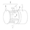
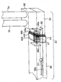
- FIG. 1 is a perspective configuration diagram of a vertical axis type Magnus-type wind power generator according to Embodiment 1 of the present invention.
- FIG. 2 is a cross-sectional view taken along the line XX ′ in FIG.
- the vertical axis Magnus type wind power generator according to the first embodiment includes a pedestal 1 and a windmill portion 2 that is rotatably disposed on the pedestal 1.
- a generator 3 is disposed in the pedestal 1, and the generator 3 is provided with a generator rotating shaft 3 a vertically above.
- the generator rotating shaft 3 a is connected to the generator 3 and the windmill unit 2. Are connected.
- the generator 3 is an inner rotor type generator, and a lower portion of the generator rotating shaft 3a is a rotor 100, and a stator 101 is provided outside thereof.
- the generator rotating shaft 3a corresponds to an example of the vertical axis of the present invention.
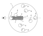
- the windmill portion 2 is provided with a disk-shaped support member 4 disposed horizontally, and a generator rotating shaft 3 a is fixed to the center of the support member 4.
- a total of eight columnar barrels 5 are arranged on the support member 4.
- FIG. 3 is a plan configuration diagram showing the arrangement of the eight barrels 5.
- These eight barrels 5 are arranged in pairs so that the support shaft 6 is perpendicular to the surface of the support member 4.
- the two barrels 5 are arranged on a radius (indicated by a two-dot chain line) from the center 4a (generator rotating shaft 3a) of the support member 4 in the circumferential direction. That is, the inner barrel 5b is disposed between the barrel 5a disposed on the outer side of the barrel set 50 and the generator rotating shaft 3a.
- the barrel 5a arranged outside and the barrel 5b arranged inside the barrel 5b are used as a barrel set 50, and four barrel sets 50 are arranged at equal intervals around the generator rotating shaft 3a.
- the four barrels 5b of the four barrel sets 50 are arranged on concentric circles at the center 4a, and the four barrels 5a are arranged on concentric circles at the center 4a. Further, the eight barrels 5 are pivotally supported by a support shaft 6 on a bearing portion 4b formed on the support member 4 so as to be capable of rotating.
- the inner barrel 5a and the outer barrel 5b have the same size, and are referred to as the barrel 5 when it is not necessary to distinguish between them.
- the support shaft 6 of the inner barrel 5b is provided with a first gear 7 below the barrel 5b, and the support shaft 6 of the outer barrel 5a is connected to the support shaft 6 of the outer barrel 5a.
- the second gear 8 is provided below the barrel 5a.
- the first gear 7 and the second gear 8 are engaged with each other.
- a motor 9 is disposed on the support member 4 outside the barrel 5 a, and a drive gear 10 is provided on a drive shaft 9 a of the motor 9.
- the drive gear 10 and the second gear 8 mesh with each other, and the driving force of the motor 9 is transmitted to the second gear 8 and the first gear 7.
- a cover member 11 is provided on the support member 4 so as to cover the first gear 7, the second gear 8 and the motor 9.
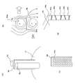
- a switching unit 14 that switches the generator 3 to a power source and a generator control unit 17 that controls the operation of the generator rotating shaft 3a by operating the switching unit 14 are provided. Further, an anemometer 15, a thermometer 18, and a snow gauge 19 are provided on the upper side of the cover member 11.
- stop detection unit of the invention related to the present invention corresponds to the rotation speed detection unit 16 of the present embodiment.
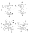
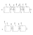
- FIG. 4 is a plan configuration diagram for explaining the operation of the vertical axis type Magnus type wind power generator according to the first embodiment.
- the outer barrel 5a rotates in the clockwise direction (arrow B) in a plan view
- the inner barrel 5b has a plan view.
- the direction of the wind is indicated by an arrow A
- the barrel set 50 on the windward side is set to 50a, and is set to 50b, 50c, and 50d in order clockwise.
- FIGS. 5 (a) to 5 (d) are diagrams illustrating the relationship between the rotation of the barrels 5a and 5b, the wind direction, and the Magnus force in each barrel set 50a to 50b.
- the Magnus force is proportional to the wind speed, the rotational angular velocity of the barrel, and the diameter of the barrel.
- the barrel 5b is disposed leeward of the barrel 5a, so that at least a part of the airflow is shielded by the barrel 5a.
- the Magnus force generated is larger than that of the barrel 5b arranged on the leeward side. Therefore, the resultant force of the Magnus force generated by the two barrels 5 a and 5 b is directed rightward and rotates the generator rotating shaft 3 a clockwise via the support member 4.
- a rightward Magnus force (arrow V3) is generated in the barrel 5a
- a leftward Magnus force (arrow V4) is generated in the barrel 5b. Since the wind speeds of the winds reaching the 5a and the barrel 5b are the same, the Magnus forces are canceled out. Even if one of the Magnus forces increases due to a manufacturing error or the like, it is a force along the radial direction, and thus does not become a force for rotating the windmill portion 2.
- the barrel 5b has a larger Magnus force generated than the barrel 5a arranged on the leeward side. Therefore, the barrel set 50 a moves in the left direction, and rotates the generator rotating shaft 3 a clockwise via the support member 4.
- a rightward Magnus force (arrow V8) is generated in the barrel 5a and a leftward Magnus force (arrow V7) is generated in the barrel 5b. Since the wind speeds of the winds reaching the 5a and the barrel 5b are the same, the Magnus forces are canceled out.
- a rightward force is generated at the position of the barrel set 50a, and a leftward force is generated at the position of the barrel set 50c. That is, when the barrel set 50 is in the region on the windward side of the generator rotating shaft 3a, the Magnus force generated in the barrel set 50 causes the support member 4 to revolve clockwise around the generator rotating shaft 3a. Even when the barrel set 50 is in the region on the leeward side with respect to the generator rotation shaft 3a, the Magnus force acts in the direction of revolving the support member 4 clockwise around the generator rotation shaft 3a. Therefore, the windmill unit 2 rotates clockwise (see arrow D) in plan view.
- the rotation of the wind turbine unit 2 causes the generator rotating shaft 3a to rotate, and the generator 3 generates power.
- the rotation speed of the generator rotation shaft 3a is detected by the rotation speed detection unit 16, and the rotation control unit 12 appropriately controls the rotation speed of the barrel 5 according to the detected rotation speed.
- the rotational speed of rotation of the barrel 5 may be controlled by the wind speed detected by the anemometer 15.
- the generator control unit 17 controls the switching unit 14 and uses the generator 3 as a power source at regular intervals.
- the generator rotating shaft 3a is rotated at a first predetermined rotation speed for a predetermined time.
- the rotation control unit 12 performs control so that the barrel 5 rotates at a rotation speed equal to or higher than the first predetermined rotation speed.
- the wind turbine unit 2 can be easily rotated even when a weak wind less than the first predetermined wind speed is blown, and the power generation state can be shifted.
- the upper predetermined second wind speed is a wind speed at which the generator rotating shaft 3a does not rotate even when the barrel 5 rotates, and is, for example, a wind speed of 1 m / s.
- the first predetermined wind speed means that the wind turbine unit 2 does not rotate only by the rotation of the barrel 5, but the generator rotation shaft 3a is driven at the first rotation speed as described above to shift to the power generation state. Is the possible wind speed, for example 3 m / s.
- the rotation control unit 12 rotates the barrel 5 at a second predetermined rotation every predetermined time. Control is performed to rotate at a rotational speed equal to or higher than the speed for a predetermined time.
- the second predetermined rotation speed is a rotation speed faster than the rotation speed by the control during power generation.
- the rotation speed detection unit 16 may detect that the generator rotating shaft 3a is rotating and generating electricity.
- the generator control unit 17 When the snow sensor 19 senses snow and the wind speed is not capable of generating power (for example, the second wind speed or less), the generator control unit 17 operates the switching unit 14 at regular intervals to generate power.
- the machine 3 is switched to the power source, and control is performed so that the generator rotating shaft 3a is driven at the second rotation speed for a predetermined time.
- the rotation control unit 12 performs control so that the barrel 5 rotates at a rotation speed equal to or higher than the second predetermined rotation speed for a predetermined time at regular time intervals.
- thermometer 18 detects that the temperature is likely to freeze and the wind speed is not possible to generate power (for example, the second wind speed or less)
- the generator controller 17 Every time the switching unit 14 is operated, the generator 3 is switched to the power source, and the generator rotating shaft 3a is controlled to be driven at the second rotational speed for a predetermined time. At this time, the rotation control unit 12 performs control to rotate the barrel 5 at a speed equal to or lower than a third predetermined rotation speed.
- the second predetermined rotation speed of the generator rotation shaft 3a is a low speed. Further, the third predetermined rotation speed of the barrel 5 is a lower speed than the second predetermined rotation speed. Even when power generation is not performed in this manner, freezing can be prevented by rotating the generator rotating shaft 3a and the barrel 5 at a low speed.
- the vertical axis Magnus type wind power generator uses the rotation of the barrel 5 in the windward-side barrel set 50 and the leeward-side barrel set 50, and thus has high power generation efficiency. Become.
- the Magnus force generated in the barrel 5a causes the support member 4 to rotate clockwise around the generator rotation shaft 3a. It is a direction to revolve, and the Magnus force generated in the barrel 5b is a direction to revolve the support member 4 counterclockwise around the generator rotation shaft 3a.
- the Magnus force generated in the barrel 5a causes the support member 4 to rotate counterclockwise.
- the direction of revolving is caused, and the Magnus force generated in the barrel 5b is the direction of revolving the support member 4 clockwise.
- the barrel 5a is leeward of the barrel 5b, at least a part of the airflow is shielded by the barrel 5b, so the Magnus force generated by the barrel 5a is smaller than the Magnus force generated by the barrel 5b.
- the airflow on both the leeward side and the leeward side of the generator rotating shaft is used to allow the generator to Can generate rotational force.
- the rotational speed of the generator rotating shaft can be controlled by measuring the wind speed or the rotating speed of the generator rotating shaft, changing the rotating speed of the barrel based on that, and adjusting the Magnus force generated in the barrel. .
- the start-up performance is improved and power generation is possible in a wide wind speed range.
- rotation speed control of the barrels 5 of the four barrel sets 50 of the first embodiment may be performed uniformly.
- Patent Document 3 which is a prior document has the following problems.
- Energy loss increases because the rotational speed of the barrel varies individually and frequently.
- the barrel has a moment of inertia, when the wind speed and the wind direction fluctuate frequently, the control of the rotation speed of the barrel cannot follow and power generation efficiency may be reduced.
- the moment of inertia of the barrel is particularly problematic when the wind power generator is enlarged.
- the moment of inertia of the barrel increases in proportion to the square of the radius, and the response of the barrel to the rotation speed control becomes worse. Therefore, a high-output motor is required to follow fluctuations in the wind direction and wind speed.
- the energy loss increases and the load on the motor and barrel also increases.
- the apparatus becomes complicated by adding a wind direction measuring unit, an azimuth angle measuring unit, etc., the manufacturing cost and the maintenance cost increase.
- Magnus wind power generator of the present embodiment by devising the arrangement of the barrel and the rotation direction, it is not affected by the wind direction, has high power generation efficiency, and has good startability.
- power generation is possible in a wide wind speed range, safety against strong winds is high, the size can be easily increased, and the system can be installed on the roof of a building or a house, or can be manufactured and operated at low cost.
- the vertical axis Magnus type wind power generator according to the second embodiment has the same basic configuration as that of the first embodiment, but supports the barrel on the lower side and supports the barrel on the upper side. The difference is that an upper support member is added. Therefore, this difference will be mainly described.
- symbol is attached
- FIG. 1 is a diagrammatic representation of Embodiment 1.
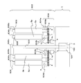
- FIG. 6 is a perspective configuration diagram of the vertical axis type Magnus type wind power generator according to the second embodiment.
- FIG. 7 is a cross-sectional view taken along the line ZZ ′ in FIG. 6 and 7, the rotation control unit 12, the rotation speed detection unit 16, the switching unit 14, the generator control unit 17, the anemometer 15, the thermometer 18, and the snow gauge 19 are omitted. Yes.
- the windmill portion 602 of the vertical axis Magnus type wind power generator according to the second embodiment is provided with a disk-like upper support member 606 for supporting the upper side of the barrel 5. Furthermore, a vertical axis 603 is provided at the center of the windmill portion 602. The lower portion of the vertical axis 603 is the rotor 100 and is integrally formed in the second embodiment, but may be separately formed and connected via the lower support member 604.
- a support shaft 609 is provided on the upper side of the barrel 5, and the support shaft 609 is rotatably fitted to the bearing portion 606 b of the upper support member 606.
- the vertical axis 603 is also rotatably fitted to a bearing part 606c formed at the lower center part of the upper support member 606.
- the lower lower support member 604 is a hollow disk-shaped member, and a bearing portion 604b that supports the support shaft 6 is formed on the ceiling portion 604s. ing.
- a first gear 7 or a second gear 8 is provided at the lower end of the support shaft 6. That is, the support shaft 6 is supported by the ceiling portion 604 s of the lower support member 604 between the barrel 5 and the first gear 7 or the second gear 8.
- the drive gear 10 of the motor 9 is engaged with the second gear 8.
- the drive gear 10 of the motor 9 is engaged with the first gear 7.
- the first gear 7 and the eighth gear are rotated by the motor 9 provided for each barrel set 50, and the barrel 5 is rotated.
- the upper support member 606 and the vertical axis 603 having the configuration of the second embodiment may be applied to the first embodiment.
- FIG. 8 is a perspective configuration diagram of the vertical axis Magnus type wind power generator having such a configuration.
- the lower support member 614 and the upper support member 616 are formed in a cross shape.
- the lower support member 614 and the upper support member 616 have center portions 614a and 616a and arm portions 614b and 616b extending in four directions from the center portions 614a and 616a, respectively.
- the angle formed by the adjacent arm portions is a right angle.
- the two barrels 5 are supported by being sandwiched between the tips of one arm portion 614b and one arm portion 616b.
- the motor 9 is provided for each barrel set 50, but the motor 9 may be provided for each barrel 5.
- FIG. 9 is a cross-sectional configuration diagram of such a vertical axis type Magnus type wind power generator viewed from the front.
- a motor 9 is provided for each support shaft 6, and the first gear 7 or the second gear 8 is provided on the support shaft 6. Is not provided.
- the vertical axis type Magnus wind turbine generator according to the third embodiment of the present invention has the same basic configuration as that of the first embodiment, but is different in the configuration for rotating the barrel 5. Therefore, this difference will be mainly described.
- symbol is attached
- the motor 9 for rotating the barrel 5 is provided for each barrel set 50, and a total of four motors are arranged. However, in the third embodiment, only one motor is provided. This single motor is configured to rotate all the barrels 5.
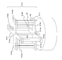
- FIG. 10 is a front cross-sectional configuration diagram of the vertical axis Magnus wind turbine generator according to the third embodiment.
- FIG. 11 is a cross-sectional configuration diagram along YY ′ in FIG. 10.
- the motor 9 corresponding to each of the barrel sets 50 is not provided, and one motor 20 is provided. ing.
- the transmission mechanism from the motor 20 to the barrel 5 corresponds to an example of the second transmission mechanism of the invention related to the present invention. The transmission mechanism will be described below.
- a driving gear 21 is provided at the tip of the motor shaft 20a arranged vertically upward from the motor 20.
- a central gear 22 is arranged at the center of the plurality of first gears 7 so as to mesh with the plurality of first gears 7, and the central gear 22 and the driving gear 21 are meshed with each other.
- the central gear 22 is rotatably supported by the bearing portion 4b of the support member 4 by a support shaft 22a.
- the support shaft 22a is provided on the center 4a of the support member 4.
- Embodiment 4 a vertical axis type Magnus wind turbine generator according to Embodiment 4 of the present invention will be described.
- the fourth embodiment is a configuration in which all barrels are rotated by one motor as in the third embodiment, except that the motor 9 is arranged on the pedestal side. Therefore, this difference will be mainly described.
- symbol is attached
- FIG. 12 is a cross-sectional configuration diagram seen from the front of the vertical axis type Magnus type wind power generator according to the fourth embodiment of the present invention.
- the rotation control unit 12, the rotation speed detection unit 16, the switching unit 14, the generator control unit 17, the anemometer 15, the thermometer 18, and the snow gauge 19 are omitted.
- the upper support member 606 and the lower support member 644 are similar to the wind turbine unit 602 having the configuration of the second embodiment.
- a vertical axis 603 and the support shaft 6 is supported by a bearing portion 644 b formed on the ceiling portion 644 s of the lower support member 644.
- the center gear 22 is disposed in the lower support member 644.
- a vertical axis 603 is disposed in a through hole formed in the center of the central gear 22, and the central gear 22 is not fixed to the vertical axis 603 but is configured to be rotatable with respect to the vertical axis 603. Yes.
- a pedestal central gear 615 is provided coaxially with the central gear 22 in the pedestal 1.
- the central gear 615 in the pedestal also has a configuration in which a vertical axis 603 is disposed in a through hole formed at the center thereof, similarly to the central gear 22, and is not fixed to the vertical axis 603, and is not fixed to the vertical axis 603. In contrast, it is configured to be rotatable. Then, the pedestal central gear 615 and the central gear 22 are connected by a connecting member 618 and rotate simultaneously.
- a drive gear 617 is provided so as to mesh with the in-pedestal center gear 615 connected to the center gear 22 in this manner, and this drive gear 617 is fixed to the drive shaft 9 a of the motor 9.
- the rotation of the motor 9 can be transmitted to the central gear 22 via the drive gear 617 and the central gear 615 in the base, so that one motor is provided as in the third embodiment. It becomes possible to rotate all barrels.
- the slip ring is not required by arranging the motor 9 on the pedestal 1 side as in the fourth embodiment, the electrical connection reliability can be improved.
- the configurations of the third and fourth embodiments are useful for small wind power generators because only one motor is required. In the case of a large size, it is preferable that a motor 9 is provided for each barrel set 50.
- Embodiment 5 a vertical axis Magnus type wind power generator according to Embodiment 5 of the present invention will be described.
- the vertical axis Magnus type wind power generator according to the fifth embodiment has the same basic configuration as that of the fourth embodiment, but in the fifth embodiment, unlike the fourth embodiment, an outer rotor type power generator. The difference is that the machine is used. Therefore, this difference will be mainly described.
- FIG. 13 is a cross-sectional configuration diagram viewed from the front of the vertical axis Magnus type wind power generator according to the fifth embodiment.
- the vertical axis Magnus type wind power generator according to the fifth embodiment is provided with a vertical axis 623 in the center of the windmill unit 622.
- the vertical axis 623 is fixed to the base 1, and the windmill unit 622 is configured to be rotatable with respect to the vertical axis 623. Therefore, in the fifth embodiment, a lower support member 654 and an upper support member 656 configured to be rotatable with respect to the vertical axis 623 are provided.
- the upper support member 656 is formed with a bearing portion 656b that supports the upper support shaft 609, and the lower support member 654 is a bearing portion 654b provided on the ceiling portion 654s, and a lower support shaft. 6 is supported.
- the generator 624 is disposed on the upper side of the lower support member 654.
- the generator 624 is an outer rotor type generator having a stator 624a provided at the center and a rotor 624b provided around the stator 624a.
- the stator 624a is constituted by a part of the longitudinal axis 623, and the rotor 624b is fixed on the lower support member 614.
- the rotor 624b of the generator 624 rotates with the rotation of the windmill unit 622 with respect to the fixed vertical axis 623 to generate power. Is called.
- an outer rotor type generator may be used.
- the rotation control unit 12, the rotation speed detection unit 16, the switching unit 14, the generator control unit 17, the anemometer 15, the thermometer 18, and the snow gauge 19 are omitted.
- the rotation speed detection unit detects the rotation of the rotor 624b, and the generator control unit moves the rotor 624b by operating the switching unit 14.
- the same control as in the first embodiment is performed, but instead of rotating the generator rotating shaft 3a, that is, the rotor 100. In this embodiment, the rotor 624b is rotated.
- Embodiment 6 a vertical axis Magnus type wind power generator according to Embodiment 6 of the present invention will be described.
- the vertical axis Magnus type wind power generator in the sixth embodiment has the same basic configuration as that of the first embodiment, but is different in control method. Therefore, this difference will be mainly described.
- symbol is attached
- FIG. 1 A vertical axis Magnus type wind power generator according to Embodiment 6 of the present invention.
- FIG. 14 is a cross-sectional configuration diagram seen from the front of the vertical axis Magnus type wind power generator according to the sixth embodiment.
- the anemometer 15 is not provided, and the time when the generator rotating shaft 3 a is stopped based on the rotation speed detected by the rotation speed detector 16.
- a stop time detector 13 is provided for detecting.
- the generator control unit 17 operates the switching unit 14 at regular time intervals to change the generator 3 Switching to the power source is performed so that the generator rotating shaft 3a is driven at a first predetermined rotational speed for a predetermined time. At this time, it is more preferable that the rotation control unit 12 controls the barrel 5 to rotate at a speed equal to or higher than the first predetermined rotation speed.
- the rotation control unit 12 Each time, the barrel 5 is controlled to rotate at a rotation speed equal to or higher than a second predetermined rotation speed for a predetermined time.
- the second predetermined rotation speed is a rotation speed faster than the rotation speed by the control during power generation.
- the snow on the barrel 5 can be dropped by rotating at a high speed for a predetermined time at a high rotational speed at regular intervals.
- the generator control unit 17 When snow is detected by the snow gauge 19 and the stop time of the generator rotating shaft 3a is longer than a predetermined time, the generator control unit 17 operates the switching unit 14 at regular intervals, and the generator 3 is switched to a power source, and the generator rotating shaft 3a is controlled to be driven at the second rotational speed for a predetermined time. At this time, the rotation control unit 12 performs control so that the barrel 5 rotates at a rotation speed equal to or higher than the second predetermined rotation speed for a predetermined time at regular time intervals.
- thermometer 18 detects that the temperature is likely to freeze and the stop time of the generator rotating shaft 3a is equal to or longer than a predetermined time
- the generator controller 17 Then, the switching unit 14 is operated to switch the generator 3 to the power source and control the generator rotating shaft 3a to be driven at the second predetermined rotation speed for a predetermined time.
- the rotation control unit 12 performs control to rotate the barrel 5 at a speed equal to or lower than a third predetermined rotation speed.
- the second predetermined rotation speed of the generator rotating shaft 3a is a low speed
- the third predetermined rotation speed of the barrel 5 is a lower speed than the second predetermined rotation speed
- thermometer 18 and the snow sensitivity meter 19 are provided, but may not be provided in an area where there is no snow accumulation or freezing.
- the operation for preventing snow accumulation or preventing freezing may be switched on and off by a manual switch or remote control.
- a cover member 111 may be provided so as to cover only the lower first gear 7, second gear and motor 9.
- the stop time of the generator rotating shaft 3a that is, the rotor 100 is detected.
- the same control as described above may be performed by detecting the stop time of the rotor 624b.
- FIG. 7 a vertical axis type Magnus wind turbine generator according to a seventh embodiment of the present invention will be described.
- the vertical axis Magnus type wind power generator according to the seventh embodiment has the same basic configuration as that of the first embodiment, but is different in that the shape of the support member is different and the structure is extendable. Therefore, this difference will be mainly described.
- symbol is attached
- FIG. 16 is a perspective configuration diagram of the vertical axis Magnus type wind power generator according to the seventh embodiment.
- the support member 40 according to the seventh embodiment has a cross shape in plan view, and the arm portion 42 protrudes in four directions from the central portion 41 to which the generator rotating shaft 3 a is fixed.
- the barrel set 50 (barrels 5a and 5b) is disposed at the tip thereof. And the angle which the adjacent arm part 42 forms is a right angle.
- FIG. 17 is an enlarged configuration diagram in the vicinity of the stretchable portion 43. Note that FIG. 17 shows a state in which the stretchable portion 43 is extended.
- the stretchable part 43 has a plurality of frame-like members 44.
- the number of frame-like members is four, and reference numerals 44a, 44b, 44c, and 44d are attached in order from the tip 42a side of the arm portion 42.
- the frame-shaped members 44a, 44b, 44c, and 44d are sequentially increased in size.
- the frame-shaped member 44a is inserted into the adjacent frame-shaped member 44b, and the frame-shaped member 44b is inserted into the adjacent frame-shaped member 44c.
- the frame-shaped member 44c is configured to be inserted into the adjacent frame-shaped member 44d.
- the frame-shaped member 44a is fixed to the outer portion 45 closer to the tip 42a than the expansion / contraction part 43 of the arm part 42, and the frame-shaped member 44d is closer to the central part 41 than the expansion / contraction part 43 of the arm part 42. It is fixed to the inner part 46.
- the outer portion 45 and the inner portion 46 have projections 45a and 46a formed therein, and a spring member 47 is fixed to the projections 45a and 46a. Both ends of the spring member 47 are fixed to the protrusions 45a and 46a, respectively, and are biased so that the expansion / contraction part 43 contracts.
- a reinforcing member 56 that connects the outer portion 45 and the inner portion 46 is provided inside the arm portion 42.
- the reinforcing member 56 is a plate-like member, and one end is fixed to the outer portion 45. Further, a long hole 56a is formed at the other end, and a pin 57 that is fitted to the long hole 56a and fixed to the inner portion 46 is provided.
- the pin 57 has a large upper end so as not to come out of the long hole 56a. That is, the reinforcing member 56 is configured to be slidable.
- a cover member 48 that covers the first gear 7, the second gear 8, the motor 9, the drive gear 10, and the like described in the first embodiment is provided above the outer portion 45 of the arm portion 42. And the barrels 5a and 5b are arrange
- the frame-like member 44 on the tip 42a side is fitted into the frame-like member 44 on the adjacent central side by the biasing force of the spring member 47, as shown in FIG. It is in a contracted state. More specifically, the frame-like member 44a is fitted into the frame-like member 44b, the frame-like member 44b is fitted into the frame-like member 44c, and the frame-like member 44c is fitted into the frame-like member 44d.
- the rotation radius is small, and the motor rotates easily even at a weak wind speed, thereby facilitating power generation.
- the stretchable part 43 is formed by four frame-shaped members, but is not limited to this.
- FIG. 19A is a perspective configuration diagram showing an airflow shielding plate 49 provided between the barrel 5a and the barrel 5b, taking Embodiment 1 as an example.
- FIG. 19B is a diagram illustrating the relationship between the rotation of the barrels 5a and 5b of the barrel set 50a and the Magnus force generated by the wind direction. As described in FIG. 4, since the Magnus force (V1) of the barrel 5a and the Magnus force (V2) generated in the barrel 5b are in opposite directions, the rotating force is weakened by the Magnus force of the barrel 5b.
- the Magnus force (V2) generated in the barrel 5b can be weakened, so that the rotating force becomes strong and the energy efficiency can be further improved. This is the same when the barrel set 50 moves to the leeward side with respect to the generator rotating shaft 3a.
- the surface of the airflow shielding plate 49 is formed with a shape that diffuses or disperses the airflow. For example, a concave portion 49a as shown in FIG. That's fine.
- the side end face 49b of the airflow shielding plate 49 is formed with a shape that diffuses or disperses the airflow.
- the plurality of protrusions 49c are formed obliquely with respect to the horizontal direction so that the interval between adjacent protrusions 49c is increased or decreased.
- the uppermost protrusion 49c in FIG. 19D is formed obliquely so that the depth side is lower than the front side of the sheet, and the second protrusion 49c on the lower side is the front side of the sheet.
- the airflow shielding plate 49 has been described as an example of the airflow shielding means of the present invention, the airflow shielding plate 49 may not be plate-shaped.
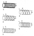
- a dimple-like recess 51 may be formed on the surface of the barrel 5 of the first to seventh embodiments as shown in FIG. Moreover, you may form the protrusion 52 as shown in FIG.20 (b). Further, as shown in FIG. 20C, ribs 53 parallel to the support shaft 6 may be formed on the surface of the barrel 5. Further, not only the rib parallel to the support shaft 6 but also a rib 54 perpendicular to the support shaft 6 may be formed on the surface of the barrel 5 as shown in FIG. Moreover, as shown in FIG.20 (e), the helical rib 55 may be formed.
- the flow of the airflow is improved, and the effect of a large Magnus force can be obtained by a little rotation, and the effect of reducing the rotational noise of the barrel 5 can also be obtained.
- FIG. 21 is a diagram showing a configuration of the barrel 105 having such a configuration.
- a barrel 105 shown in FIG. 21 is hollow, and a support shaft 106 is disposed at the center thereof.
- the support shaft 106 and the barrel 105 are connected by a support arm 107.
- FIG. 22 is an exploded perspective view of such a barrel 630.
- the barrel 630 includes two cylindrical parts 631 and 632 arranged in order from the top, an upper support shaft part 633 arranged on the upper side of the cylindrical part 631, and the cylindrical part 631 and the cylindrical part 632. It has a connecting portion 634 that connects between them, and a lower support shaft portion 635 that is disposed below the cylindrical portion 632.
- These cylindrical portions 631 and 632 are hollow, and screw through-holes 631a, 631b, 632a, and 632b are formed at four positions in the vertical direction.
- the upper support shaft portion 633 includes an upper support shaft 633a, a fitting portion 633b that fits into the cylindrical portion 631, and a columnar portion 633c formed between the upper support shaft 633a and the fitting portion 633b.
- the fitting portion 633b has four screw holes 633d.
- the connecting portion 634 includes a fitting portion 634a that fits inside the cylindrical portion 631, a fitting portion 634b that fits inside the cylindrical portion 632, and a columnar portion 634c formed between the fitting portion 634a and the fitting portion 634b. have.
- the fitting portion 634a has four screw holes 634d
- the fitting portion 634b has four screw holes 634e.
- the lower support shaft portion 635 includes a lower support shaft 635a, a fitting portion 635b that fits inside the cylindrical portion 632, and a columnar portion 635c provided between the lower support shaft 635a and the fitting portion 635b.
- the fitting portion 635b has four screw holes 635d.
- These cylindrical portions 631 and 632 and column portions 633c, 634c, and 635c all have the same diameter.
- corresponds to the cylindrical parts 631 and 632, or the column parts 633c, 634c, and 635c.
- the fitting portion 633b of the upper support shaft portion 633 and the fitting portion 634a of the connection portion 634 are fitted inside the cylindrical portion 631, and the fitting portion 634b of the connection portion 634 and the fitting portion 635b of the lower support shaft portion 635 are fitted.
- Fit inside the cylindrical portion 632 match the screw hole 633d and the through hole 631a, match the screw hole 634d and the through hole 631b, match the screw hole 634e and the through hole 632a, match the screw hole 635d and the through hole 632b, respectively.
- the upper support shaft 633a corresponds to the upper support shaft 609 of the barrel 5 in FIG. 7
- the lower support shaft 635a corresponds to the support shaft 6 of the barrel 5 in FIG.
- FIG. 23A is a perspective configuration diagram of such a barrel 205.
- FIG. 23B is a perspective configuration diagram illustrating a state where the barrel 205 is divided.
- the barrel 205 includes a plurality of barrel portions 251, 252, and 253 arranged in order from the top.
- the barrel portion 251 located at the uppermost portion has a connecting shaft 61 on the lower side thereof, and the barrel portion 252 located at the center is provided with a connecting shaft 62 provided on the upper side thereof and on the lower side thereof.
- a connecting shaft 63 is provided on the upper side thereof and on the lower side thereof.
- the barrel portion 253 located at the lowermost portion has a connecting shaft 64 provided on the upper side and a support shaft 65 provided on the lower side.
- the connecting shafts 61, 62, 63, 64 are hollow, and through holes 61a, 62a, 63a, 64a are formed, respectively.
- the connecting shaft 61 of the barrel portion 251 is fitted inside the connecting shaft 62 of the barrel portion 252, and the positions of the through hole 61a and the through hole 62a are aligned.
- the barrel 251 and the barrel 252 are fixed by inserting the pin 254 into the through holes 61a and 62a.
- the connecting shaft 63 of the barrel portion 252 is fitted inside the connecting shaft 64 of the barrel portion 253, and the pin 254 is inserted into the through holes 63a and 64a with the positions of the through hole 63a and the through hole 64a being aligned.
- the first gear 7 and the second gear 8 are arranged on the support shaft 65.
- FIG. 22 an upper support shaft 633a and a lower support shaft 635a are provided.
- a lower support shaft 65 is provided, but only the upper support shaft is provided. (Not shown). Also, the barrel 5 that is not divided may be supported only by the upper support shaft 609 (not shown).
- a disk-shaped support member is used, but it may be configured to exhibit a flywheel effect. Specifically, it can be formed of metal or the like so as to increase the mass.
- the material of the central portion 204a and the peripheral portion 204b is changed, and the mass per unit volume is heavier than the material of the central portion 204a as the material of the peripheral portion 204b. What is necessary is just to use.
- a weight 605 may be disposed on the entire lower side of the lower support member 604 (see FIG. 6), or as shown in FIG. A weight 608 may be disposed around the lower side of the side support member 604.
- the material of the outer part 45 is heavier than the material of the central part 41 and the inner part 46. It may be used.
- FIG. 8 a cross-shaped support member 400 used in the modification of the second embodiment shown in FIG. 8 is shown in FIG.
- the support member 400 has a cross shape in plan view, and includes a central portion 401 to which the generator rotating shaft 3a and the vertical axis 603 are fixed, and an arm portion 402 formed so as to protrude in four directions from the central portion 401.
- the flywheel effect can be provided by forming the annular member 402b that connects the tip 402a of the arm portion 402 in an annular shape. I can do it.
- the four barrel sets 50 are provided.
- the number may be three or less, or five or more.
- the adjacent barrel groups 50 and the generator rotating shaft 3a are arranged so that the angle formed by each is approximately 120 degrees.
- the generator rotation shaft 3a is arranged at equal intervals, only one barrel set 50 may be arranged. Only one set may be provided.
- FIG. 27 is a plan configuration diagram of the support member 410.
- the support member 410 is fixed to the generator rotating shaft 3a at the center 410a, and the bearing portion 411 that rotatably arranges the support shaft 6 of the outer barrel 5 and the support shaft 6 of the inner barrel 5 rotate.
- a bearing portion 412 that can be arranged is provided.
- 12 sets of the bearing portion 411 and the bearing portion 412 are formed.
- the angles (see ⁇ in the figure) formed by the line connecting the pair of adjacent bearing portions 412 and 411 and the center 410a are all equal.
- the support member 410 formed in this manner it is possible to select one, two, three, four, six, or twelve barrel sets 50 to be used. In the case of two, three, four, and six, it is preferable that the barrel sets 50 are arranged at equal intervals around the center 410a.
- the cover member 11 is also formed with 12 holes, through which a total of 24 support shafts 6 pass, with the inner support shaft 6 and the outer support shaft 6 as one set. Yes.
- FIG. 28 is a perspective configuration diagram showing a configuration in which a frame structure 500 is added to the configuration of the second embodiment shown in FIG.
- the vertical axis 603 protrudes from the upper support member 606, and the upper frame member 501 that rotatably supports the upper end of the vertical axis 603, the upper frame member 501, and the base 1 are connected to each other.
- the upper frame member 501 includes a central portion 501a where the vertical axis 603 is disposed, and an arm portion 501b extending from the central portion 501a to the side frame portion 503.
- FIG. 29 is a diagram showing such a configuration. As shown in FIG. 29, a vertical frame 660 is provided from the lower support member 604 at a position intermediate between the plurality of barrel sets so as to support the upper support member 606.
- FIG. 30 is a plan view of a vertical axis Magnus type wind power generator in which four barrel sets 50 are arranged. As shown in FIG. 30, rectifying plates 502 are provided outside the support member 4 toward the center 4 a at intervals of 60 degrees. By arranging the current plate 502 in this way, the wind is directed in the direction toward the vertical axis of the wind turbine unit, so that the shielding amount of the barrel on the leeward side is increased, and power can be generated efficiently. Further, a rectifying plate may be provided between the barrel set 50 and the center 4a (coincident with the vertical axis).
- the center of the barrel 5b is arranged on a line connecting the barrel 5a and the center 4a (coincident with the vertical axis), but the present invention is not limited to this. And the center 4a.
- the region S is a region between two tangents L and M on the outer periphery of the barrel 5a, which is parallel to a straight line connecting the barrel 5a and the vertical axis.
- the barrel 5b is preferably arranged so that at least a part thereof is placed on a line connecting the barrel 5a and the longitudinal axis of the center 4a.
- an electric power storage means for storing the electric power generated by the generator and the electric power generated by the solar cell may be provided inside the pedestal of the vertical axis Magnus type wind power generator of the present invention.
- the power storage means, the commercial power source and the like are appropriately selected and used. I can do it.
- the motor 9 that rotates the barrel 5 is not limited to an AC motor, and may be a DC motor.
- a DC motor is used and a storage battery is used as the power storage means, the power stored in the storage battery can be used as a direct current.
- control may be performed as follows. An electromagnetic brake or the like may be used for this stop.
- the rotational torque in the same direction is generated with respect to the generator rotation shaft in both the windward and leeward regions of the generator rotation shaft without being affected by the wind direction. , Power generation efficiency is high.
- the startability is improved, and power can be generated in a wide wind speed range.
- the wind power generator according to the present invention does not require individual and frequent control of the rotation speed of the barrel, and a decrease in the response of the barrel to the rotation speed control when the size is increased leads to a decrease in power generation efficiency. It is difficult to increase the size.
- the wind power generator of the present invention does not require a high tower like a horizontal axis type wind power generator, it can be installed on the roof of a building or a house.
- wind power generator of the present invention can be installed near the ground, and maintenance is easy.
- the barrel-shaped blade is easy to manufacture and does not require a wind direction measuring device or the like and has a simple configuration, manufacturing costs and maintenance costs can be reduced.
- the present invention it is not affected by the wind direction, has high power generation efficiency, good startability, can generate power in a wide wind speed range, has high safety against strong winds, is easy to increase in size, It is possible to provide a wind power generator that can be installed on a roof such as a house and can be manufactured and operated at a lower cost.
- the vertical axis type Magnus type wind power generator of the present invention has high power generation efficiency, exhibits an effect of simple control, and is useful as a wind power generator in an environment where the wind speed is low as in Japan.
Landscapes
- Engineering & Computer Science (AREA)
- Life Sciences & Earth Sciences (AREA)
- Sustainable Development (AREA)
- Sustainable Energy (AREA)
- Chemical & Material Sciences (AREA)
- Combustion & Propulsion (AREA)
- Mechanical Engineering (AREA)
- General Engineering & Computer Science (AREA)
- Wind Motors (AREA)
Abstract
Priority Applications (4)
| Application Number | Priority Date | Filing Date | Title |
|---|---|---|---|
| CN201280035643.9A CN103717884A (zh) | 2011-07-22 | 2012-06-08 | 垂直轴型马格努斯式风力发电机 |
| US14/007,357 US20140008916A1 (en) | 2011-07-22 | 2012-06-08 | Vertical axis type magnus wind turbine generator |
| EP20120817685 EP2735733A4 (fr) | 2011-07-22 | 2012-06-08 | Générateur éolien magnus de type à axe vertical |
| JP2012541259A JP5209826B1 (ja) | 2011-07-22 | 2012-06-08 | 垂直軸型マグナス式風力発電機 |
Applications Claiming Priority (2)
| Application Number | Priority Date | Filing Date | Title |
|---|---|---|---|
| JP2011-160967 | 2011-07-22 | ||
| JP2011160967 | 2011-07-22 |
Publications (1)
| Publication Number | Publication Date |
|---|---|
| WO2013014848A1 true WO2013014848A1 (fr) | 2013-01-31 |
Family
ID=47600726
Family Applications (1)
| Application Number | Title | Priority Date | Filing Date |
|---|---|---|---|
| PCT/JP2012/003762 WO2013014848A1 (fr) | 2011-07-22 | 2012-06-08 | Générateur éolien magnus de type à axe vertical |
Country Status (5)
| Country | Link |
|---|---|
| US (1) | US20140008916A1 (fr) |
| EP (1) | EP2735733A4 (fr) |
| JP (1) | JP5209826B1 (fr) |
| CN (1) | CN103717884A (fr) |
| WO (1) | WO2013014848A1 (fr) |
Cited By (5)
| Publication number | Priority date | Publication date | Assignee | Title |
|---|---|---|---|---|
| JP2017061862A (ja) * | 2015-09-24 | 2017-03-30 | 株式会社シルフィード | 小形風力発電機のブレーキ制御方法及び小形風力発電機 |
| KR101949044B1 (ko) | 2017-11-23 | 2019-02-15 | 정태일 | 타워형 태양광발전장치 |
| US10443564B2 (en) | 2015-07-01 | 2019-10-15 | Challenergy Inc. | Magnus type thrust generating device |
| JP2020016169A (ja) * | 2018-07-24 | 2020-01-30 | 株式会社チャレナジー | マグナス式推力発生装置、前記マグナス式推力発生装置を用いた風力回転装置、水力回転装置、潮力回転装置、ならびに前記マグナス式推力発生装置を用いた風力発電機、水力発電機、潮力発電機 |
| CN115539293A (zh) * | 2022-09-21 | 2022-12-30 | 石家庄铁道大学 | 马格努斯式风轮及风力机 |
Families Citing this family (11)
| Publication number | Priority date | Publication date | Assignee | Title |
|---|---|---|---|---|
| PL218215B1 (pl) * | 2012-06-26 | 2014-10-31 | Jerzy Bolesław Wasilewski | Turbina wiatrowa |
| FI127248B (en) * | 2017-01-11 | 2018-02-15 | Norsepower Oy | Prevention of ice formation on a Magnus rotor |
| US10598187B2 (en) * | 2017-08-22 | 2020-03-24 | Asia Vital Components Co., Ltd. | Heat-dissipation fan with cylindrical fan blades |
| WO2019157483A2 (fr) * | 2018-02-12 | 2019-08-15 | Holohan Eric | Procédés et systèmes pour un système de rotor océanique verticalement variable |
| CN108590963A (zh) * | 2018-05-03 | 2018-09-28 | 南京师范大学 | 一种垂直轴风力机圆柱转子叶片的变速驱动控制策略 |
| TWI710698B (zh) * | 2019-12-03 | 2020-11-21 | 周中奇 | 垂直軸流體能量轉換裝置 |
| US11125207B2 (en) * | 2020-01-02 | 2021-09-21 | Edwin Steven Newman | Magnus rotors as a means of improving the performance of Savonius rotors and vehicles |
| CN112594110A (zh) * | 2020-12-01 | 2021-04-02 | 西北工业大学 | 一种基于马格努斯效应的垂直轴海流能发电装置 |
| CN113883003A (zh) * | 2021-10-19 | 2022-01-04 | 南京师范大学中北学院 | 一种利用电机空余驱动能力的飞轮蓄能装置及运行方法 |
| CN113883002A (zh) * | 2021-10-19 | 2022-01-04 | 南京师范大学中北学院 | 一种风力机转子叶片能量回收与释放装置及其运行方法 |
| CN113982822A (zh) * | 2021-10-19 | 2022-01-28 | 南京师范大学中北学院 | 一种轮轨式风力机转子叶片驱动换向装置及其运行方法 |
Citations (4)
| Publication number | Priority date | Publication date | Assignee | Title |
|---|---|---|---|---|
| JP2007085327A (ja) | 2004-02-09 | 2007-04-05 | Mekaro Akita:Kk | マグナス型風力発電装置 |
| JP2008175070A (ja) | 2007-01-16 | 2008-07-31 | Kansai Electric Power Co Inc:The | 縦軸マグナス型風力発電機 |
| JP2010121518A (ja) | 2008-11-19 | 2010-06-03 | Mitsubishi Heavy Ind Ltd | 縦軸式マグナス型風力発電装置 |
| JP2010223207A (ja) * | 2009-03-21 | 2010-10-07 | Kiyoshi Mitsui | 垂直型反動風車発電機 |
Family Cites Families (7)
| Publication number | Priority date | Publication date | Assignee | Title |
|---|---|---|---|---|
| DE3043169A1 (de) * | 1980-11-15 | 1982-06-03 | Alfons 6000 Frankfurt Eul | Stroemungsmaschine |
| BE896024A (nl) * | 1983-02-25 | 1983-06-16 | Vandervelden Etienne | Windenergieomzettingssysteem, aangedreven door een combinatie van flettner-en savoniusrotors |
| BE898501R (nl) * | 1983-12-19 | 1984-04-16 | Vandervelden Etienne | Windenergieomzettingssysteem, aangedreven door een combinatie van Flettner- en Savoniusrotors. |
| BE898634R (nl) * | 1984-01-09 | 1984-05-02 | Vandervelden Etienne | Windenergieomzettingssysteem, aangedreven door een combinatie van flettner- en savoniusrotors |
| DE3503059A1 (de) * | 1985-01-30 | 1986-07-31 | Georg Dipl.-Ing. Appeltshauser (FH), 7000 Stuttgart | Rotorgetriebene windkraftanlage |
| US6857846B2 (en) * | 2001-06-19 | 2005-02-22 | Lewis H. Miller | Stackable vertical axis windmill |
| CA2552297C (fr) * | 2004-02-09 | 2010-08-10 | Mekaro Akita Co., Ltd. | Generateur d'energie eolienne de type magnus |
-
2012
- 2012-06-08 CN CN201280035643.9A patent/CN103717884A/zh active Pending
- 2012-06-08 JP JP2012541259A patent/JP5209826B1/ja not_active Expired - Fee Related
- 2012-06-08 EP EP20120817685 patent/EP2735733A4/fr not_active Withdrawn
- 2012-06-08 US US14/007,357 patent/US20140008916A1/en not_active Abandoned
- 2012-06-08 WO PCT/JP2012/003762 patent/WO2013014848A1/fr active Application Filing
Patent Citations (4)
| Publication number | Priority date | Publication date | Assignee | Title |
|---|---|---|---|---|
| JP2007085327A (ja) | 2004-02-09 | 2007-04-05 | Mekaro Akita:Kk | マグナス型風力発電装置 |
| JP2008175070A (ja) | 2007-01-16 | 2008-07-31 | Kansai Electric Power Co Inc:The | 縦軸マグナス型風力発電機 |
| JP2010121518A (ja) | 2008-11-19 | 2010-06-03 | Mitsubishi Heavy Ind Ltd | 縦軸式マグナス型風力発電装置 |
| JP2010223207A (ja) * | 2009-03-21 | 2010-10-07 | Kiyoshi Mitsui | 垂直型反動風車発電機 |
Cited By (7)
| Publication number | Priority date | Publication date | Assignee | Title |
|---|---|---|---|---|
| US10443564B2 (en) | 2015-07-01 | 2019-10-15 | Challenergy Inc. | Magnus type thrust generating device |
| JP2017061862A (ja) * | 2015-09-24 | 2017-03-30 | 株式会社シルフィード | 小形風力発電機のブレーキ制御方法及び小形風力発電機 |
| KR101949044B1 (ko) | 2017-11-23 | 2019-02-15 | 정태일 | 타워형 태양광발전장치 |
| JP2020016169A (ja) * | 2018-07-24 | 2020-01-30 | 株式会社チャレナジー | マグナス式推力発生装置、前記マグナス式推力発生装置を用いた風力回転装置、水力回転装置、潮力回転装置、ならびに前記マグナス式推力発生装置を用いた風力発電機、水力発電機、潮力発電機 |
| JP7161748B2 (ja) | 2018-07-24 | 2022-10-27 | 株式会社チャレナジー | マグナス式推力発生装置、前記マグナス式推力発生装置を用いた風力回転装置、水力回転装置、潮力回転装置、ならびに前記マグナス式推力発生装置を用いた風力発電機、水力発電機、潮力発電機 |
| CN115539293A (zh) * | 2022-09-21 | 2022-12-30 | 石家庄铁道大学 | 马格努斯式风轮及风力机 |
| CN115539293B (zh) * | 2022-09-21 | 2023-12-12 | 石家庄铁道大学 | 马格努斯式风轮及风力机 |
Also Published As
| Publication number | Publication date |
|---|---|
| EP2735733A1 (fr) | 2014-05-28 |
| JPWO2013014848A1 (ja) | 2015-02-23 |
| JP5209826B1 (ja) | 2013-06-12 |
| CN103717884A (zh) | 2014-04-09 |
| EP2735733A4 (fr) | 2015-03-04 |
| US20140008916A1 (en) | 2014-01-09 |
Similar Documents
| Publication | Publication Date | Title |
|---|---|---|
| JP5209826B1 (ja) | 垂直軸型マグナス式風力発電機 | |
| US8258647B2 (en) | Vertical axis wind turbine | |
| US9404477B2 (en) | Proportional moving air power transmission and energy collection and control system | |
| EP3635248B1 (fr) | Conception de profil aérodynamique segmentée pour fils-guide | |
| US11359608B2 (en) | Segmented airfoil design for guide wires | |
| WO2009029509A2 (fr) | Turbine d'éolienne à auto-rupture et à axe vertical | |
| US20130129509A1 (en) | Vertical axis wind turbine | |
| KR20130069334A (ko) | 풍력 에너지로부터 전력을 발생시키기 위한 풍력 발전 장치 | |
| US20210207577A1 (en) | Scalable Wind Power Station | |
| US20150084341A1 (en) | Vertical axis turbine and constructions employing same | |
| EP2459873B1 (fr) | Turbine éolienne | |
| KR101235683B1 (ko) | 풍력발전기의 블레이드의 가변구조 | |
| KR20090084066A (ko) | 바람과 수평으로 회전하는 가변날개가 장착된 풍력발전기 | |
| CN210622978U (zh) | 一种垂直轴风力发电机的风轮 | |
| KR20100118741A (ko) | 다단 풍력발전장치 | |
| KR101650544B1 (ko) | 수직축 풍력 발전장치 및 이에 구비되는 회전체 | |
| US20100266383A1 (en) | Balanced sail wind turbine | |
| RU2461733C9 (ru) | Ветроагрегат | |
| RU2705531C1 (ru) | Ротор вертикально-осевой ветряной установки | |
| KR20130025477A (ko) | 터빈 블레이드 및 이를 구비한 풍력 발전기 | |
| KR20100116494A (ko) | 면적 조절이 가능한 슬라이딩 방식 풍력발전용 회전날개 | |
| KR20100100435A (ko) | 수평으로 설치되는 풍력발전기용 풍차 |
Legal Events
| Date | Code | Title | Description |
|---|---|---|---|
| ENP | Entry into the national phase |
Ref document number: 2012541259 Country of ref document: JP Kind code of ref document: A |
|
| 121 | Ep: the epo has been informed by wipo that ep was designated in this application |
Ref document number: 12817685 Country of ref document: EP Kind code of ref document: A1 |
|
| WWE | Wipo information: entry into national phase |
Ref document number: 14007357 Country of ref document: US |
|
| WWE | Wipo information: entry into national phase |
Ref document number: 2012817685 Country of ref document: EP |
|
| NENP | Non-entry into the national phase |
Ref country code: DE |