WO2013005457A1 - Dispositif de conversion électrique - Google Patents
Dispositif de conversion électrique Download PDFInfo
- Publication number
- WO2013005457A1 WO2013005457A1 PCT/JP2012/056345 JP2012056345W WO2013005457A1 WO 2013005457 A1 WO2013005457 A1 WO 2013005457A1 JP 2012056345 W JP2012056345 W JP 2012056345W WO 2013005457 A1 WO2013005457 A1 WO 2013005457A1
- Authority
- WO
- WIPO (PCT)
- Prior art keywords
- switch
- smoothing capacitor
- discharge path
- inrush current
- current prevention
- Prior art date
Links
Images


Classifications
-
- H—ELECTRICITY
- H02—GENERATION; CONVERSION OR DISTRIBUTION OF ELECTRIC POWER
- H02M—APPARATUS FOR CONVERSION BETWEEN AC AND AC, BETWEEN AC AND DC, OR BETWEEN DC AND DC, AND FOR USE WITH MAINS OR SIMILAR POWER SUPPLY SYSTEMS; CONVERSION OF DC OR AC INPUT POWER INTO SURGE OUTPUT POWER; CONTROL OR REGULATION THEREOF
- H02M7/00—Conversion of ac power input into dc power output; Conversion of dc power input into ac power output
- H02M7/02—Conversion of ac power input into dc power output without possibility of reversal
- H02M7/04—Conversion of ac power input into dc power output without possibility of reversal by static converters
- H02M7/12—Conversion of ac power input into dc power output without possibility of reversal by static converters using discharge tubes with control electrode or semiconductor devices with control electrode
- H02M7/125—Avoiding or suppressing excessive transient voltages or currents
-
- H—ELECTRICITY
- H02—GENERATION; CONVERSION OR DISTRIBUTION OF ELECTRIC POWER
- H02M—APPARATUS FOR CONVERSION BETWEEN AC AND AC, BETWEEN AC AND DC, OR BETWEEN DC AND DC, AND FOR USE WITH MAINS OR SIMILAR POWER SUPPLY SYSTEMS; CONVERSION OF DC OR AC INPUT POWER INTO SURGE OUTPUT POWER; CONTROL OR REGULATION THEREOF
- H02M1/00—Details of apparatus for conversion
- H02M1/42—Circuits or arrangements for compensating for or adjusting power factor in converters or inverters
- H02M1/4208—Arrangements for improving power factor of AC input
- H02M1/4233—Arrangements for improving power factor of AC input using a bridge converter comprising active switches
-
- H—ELECTRICITY
- H02—GENERATION; CONVERSION OR DISTRIBUTION OF ELECTRIC POWER
- H02M—APPARATUS FOR CONVERSION BETWEEN AC AND AC, BETWEEN AC AND DC, OR BETWEEN DC AND DC, AND FOR USE WITH MAINS OR SIMILAR POWER SUPPLY SYSTEMS; CONVERSION OF DC OR AC INPUT POWER INTO SURGE OUTPUT POWER; CONTROL OR REGULATION THEREOF
- H02M7/00—Conversion of ac power input into dc power output; Conversion of dc power input into ac power output
- H02M7/02—Conversion of ac power input into dc power output without possibility of reversal
- H02M7/04—Conversion of ac power input into dc power output without possibility of reversal by static converters
- H02M7/06—Conversion of ac power input into dc power output without possibility of reversal by static converters using discharge tubes without control electrode or semiconductor devices without control electrode
- H02M7/066—Conversion of ac power input into dc power output without possibility of reversal by static converters using discharge tubes without control electrode or semiconductor devices without control electrode particular circuits having a special characteristic
-
- Y—GENERAL TAGGING OF NEW TECHNOLOGICAL DEVELOPMENTS; GENERAL TAGGING OF CROSS-SECTIONAL TECHNOLOGIES SPANNING OVER SEVERAL SECTIONS OF THE IPC; TECHNICAL SUBJECTS COVERED BY FORMER USPC CROSS-REFERENCE ART COLLECTIONS [XRACs] AND DIGESTS
- Y02—TECHNOLOGIES OR APPLICATIONS FOR MITIGATION OR ADAPTATION AGAINST CLIMATE CHANGE
- Y02B—CLIMATE CHANGE MITIGATION TECHNOLOGIES RELATED TO BUILDINGS, e.g. HOUSING, HOUSE APPLIANCES OR RELATED END-USER APPLICATIONS
- Y02B70/00—Technologies for an efficient end-user side electric power management and consumption
- Y02B70/10—Technologies improving the efficiency by using switched-mode power supplies [SMPS], i.e. efficient power electronics conversion e.g. power factor correction or reduction of losses in power supplies or efficient standby modes
Landscapes
- Engineering & Computer Science (AREA)
- Power Engineering (AREA)
- Inverter Devices (AREA)
- Rectifiers (AREA)
- Dc-Dc Converters (AREA)
Abstract
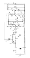
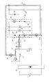
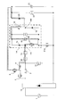
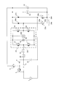
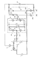
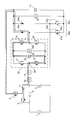
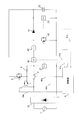
L'invention concerne l'obtention d'un dispositif de conversion électrique de petite taille et peu coûteux en réduisant le nombre des composants qui le constituent. L'invention concerne donc un dispositif de conversion électrique qui comporte : un circuit inverseur (14) connecté à l'étage suivant d'une alimentation électrique alternative (1) ; un condensateur de filtrage (22) connecté par un élément redresseur (20) à l'étage suivant du circuit inverseur (14) ; un commutateur de charge (2) connecté à l'étage précédent du circuit inverseur (14) et fonctionnant de manière à injecter au circuit inverseur (14) une quantité d'électricité, en fonction de la sortie de l'alimentation électrique alternative (1), lorsque ledit commutateur est ouvert et à intercepter la quantité d'électricité injectée au circuit inverseur (14) lorsqu'il est fermé ; un circuit de prévention de courant d'appel(7) qui comprend un commutateur de prévention de courant d'appel (3) et une résistance de prévention de courant d'appel (4) montés en série avec l'étage suivant du commutateur de prévention de courant d'appel (3). Le circuit de prévention de courant d'appel (7) est caractérisé en ce qu'il est connecté en parallèle avec le commutateur de charge (2).
Priority Applications (6)
| Application Number | Priority Date | Filing Date | Title |
|---|---|---|---|
| CN201280019172.2A CN103493353B (zh) | 2011-07-06 | 2012-03-13 | 功率转换装置 |
| US14/002,786 US9484831B2 (en) | 2011-07-06 | 2012-03-13 | Electric-power conversion system |
| EP12807802.9A EP2731248B1 (fr) | 2011-07-06 | 2012-03-13 | Dispositif de conversion électrique |
| US14/882,529 US9634574B2 (en) | 2011-07-06 | 2015-10-14 | Electric-power conversion system having inrush current prevention circuit |
| US14/882,523 US9608536B2 (en) | 2011-07-06 | 2015-10-14 | Electric-power conversion system including single-phase inverter |
| US14/882,515 US9608535B2 (en) | 2011-07-06 | 2015-10-14 | Electric-power conversion system having plurality of single-phase inverter circuits |
Applications Claiming Priority (2)
| Application Number | Priority Date | Filing Date | Title |
|---|---|---|---|
| JP2011149764A JP5230777B2 (ja) | 2011-07-06 | 2011-07-06 | 電力変換装置 |
| JP2011-149764 | 2011-07-06 |
Related Child Applications (3)
| Application Number | Title | Priority Date | Filing Date |
|---|---|---|---|
| US14/002,786 A-371-Of-International US9484831B2 (en) | 2011-07-06 | 2012-03-13 | Electric-power conversion system |
| US14/882,529 Division US9634574B2 (en) | 2011-07-06 | 2015-10-14 | Electric-power conversion system having inrush current prevention circuit |
| US14/882,515 Division US9608535B2 (en) | 2011-07-06 | 2015-10-14 | Electric-power conversion system having plurality of single-phase inverter circuits |
Publications (1)
| Publication Number | Publication Date |
|---|---|
| WO2013005457A1 true WO2013005457A1 (fr) | 2013-01-10 |
Family
ID=47436818
Family Applications (1)
| Application Number | Title | Priority Date | Filing Date |
|---|---|---|---|
| PCT/JP2012/056345 WO2013005457A1 (fr) | 2011-07-06 | 2012-03-13 | Dispositif de conversion électrique |
Country Status (5)
| Country | Link |
|---|---|
| US (4) | US9484831B2 (fr) |
| EP (1) | EP2731248B1 (fr) |
| JP (1) | JP5230777B2 (fr) |
| CN (1) | CN103493353B (fr) |
| WO (1) | WO2013005457A1 (fr) |
Cited By (2)
| Publication number | Priority date | Publication date | Assignee | Title |
|---|---|---|---|---|
| JP2014057452A (ja) * | 2012-09-13 | 2014-03-27 | Mitsubishi Electric Corp | 電力変換装置及び電源システム |
| CN110880859A (zh) * | 2018-09-06 | 2020-03-13 | 三菱电机株式会社 | 半导体模块及电力转换装置 |
Families Citing this family (14)
| Publication number | Priority date | Publication date | Assignee | Title |
|---|---|---|---|---|
| EP2517341B1 (fr) * | 2009-12-23 | 2019-06-26 | Marvell World Trade Ltd. | Alimentation de démarrage pour une alimentation à découpage |
| WO2012158496A2 (fr) | 2011-05-16 | 2012-11-22 | Marvell World Trade Ltd. | Circuit de démarrage à haute tension |
| US9876438B2 (en) * | 2015-03-19 | 2018-01-23 | Mitsubishi Electric Corporation | Converter unit system having inrush-current suppression circuit |
| JP6129450B1 (ja) * | 2016-02-08 | 2017-05-17 | 三菱電機株式会社 | 電力変換装置 |
| EP3416276B1 (fr) * | 2016-02-08 | 2020-01-08 | Mitsubishi Electric Corporation | Dispositif de conversion de courant |
| EP3301805A1 (fr) * | 2016-09-30 | 2018-04-04 | Fronius International GmbH | Procédé destiné au fonctionnement d'un onduleur et onduleur |
| JP6522568B2 (ja) * | 2016-10-17 | 2019-05-29 | コーセル株式会社 | スイッチング電源装置及びその制御方法 |
| DE102017204044A1 (de) * | 2017-02-14 | 2018-08-16 | Ellenberger & Poensgen Gmbh | Verfahren und Spannungsvervielfacher zur Wandlung einer Eingangsspannung sowie Trennschaltung |
| JP6923337B2 (ja) * | 2017-03-30 | 2021-08-18 | 住友重機械工業株式会社 | パワーコンポーネント |
| JP6945170B2 (ja) * | 2017-04-24 | 2021-10-06 | パナソニックIpマネジメント株式会社 | 電力変換システム |
| KR20210023033A (ko) * | 2019-08-21 | 2021-03-04 | 엘지전자 주식회사 | 전력 변환 회로, 인버터 장치 및 인버터 장치의 구동 방법 |
| US11258248B2 (en) * | 2020-01-08 | 2022-02-22 | Astee International Limited | Input overvoltage protection circuits for power supplies |
| US20230336092A1 (en) * | 2020-12-23 | 2023-10-19 | Mitsubishi Electric Corporation | Power conversion device |
| CN114551156B (zh) * | 2022-02-28 | 2023-08-29 | 西安思丹德信息技术有限公司 | 一种控制容性负载的继电器触点保护电路 |
Citations (6)
| Publication number | Priority date | Publication date | Assignee | Title |
|---|---|---|---|---|
| JPS62107591U (fr) * | 1985-12-23 | 1987-07-09 | ||
| JPH06245485A (ja) * | 1993-02-18 | 1994-09-02 | Toshiba Corp | インバータ装置 |
| JPH0833338A (ja) * | 1994-07-15 | 1996-02-02 | Matsushita Electric Works Ltd | 平滑コンデンサの放電回路 |
| JP2005318754A (ja) * | 2004-04-30 | 2005-11-10 | Mitsubishi Electric Corp | 電動機駆動用インバータ装置 |
| WO2007129469A1 (fr) * | 2006-05-08 | 2007-11-15 | Mitsubishi Electric Corporation | Dispositif de transduction d'energie |
| JP2009095160A (ja) | 2007-10-10 | 2009-04-30 | Mitsubishi Electric Corp | 電力変換装置 |
Family Cites Families (20)
| Publication number | Priority date | Publication date | Assignee | Title |
|---|---|---|---|---|
| JPH07288979A (ja) * | 1994-04-18 | 1995-10-31 | Japan Steel Works Ltd:The | コンバータ回路および電動射出成形機 |
| US6445165B1 (en) * | 2001-09-21 | 2002-09-03 | International Business Machines Corporation | Circuit for limiting inrush current to a power source |
| US7068016B2 (en) * | 2002-11-01 | 2006-06-27 | International Rectifier Corporation | One cycle control PFC boost converter integrated circuit with inrush current limiting, fan motor speed control and housekeeping power supply controller |
| US6949915B2 (en) * | 2003-07-24 | 2005-09-27 | Harman International Industries, Incorporated | Opposed current converter power factor correcting power supply |
| US6930483B2 (en) * | 2003-08-01 | 2005-08-16 | General Electric Company | Method/system for switched frequency ripple reduction in MRI gradient coils |
| JP4043481B2 (ja) * | 2004-06-25 | 2008-02-06 | 三洋電機株式会社 | インバータ装置 |
| US7276883B2 (en) | 2004-08-12 | 2007-10-02 | International Rectifier Corporation | Self-driven synchronous rectified boost converter with inrush current protection using bidirectional normally on device |
| US7355368B2 (en) | 2004-08-12 | 2008-04-08 | International Rectifier Corporation | Efficient in-rush current limiting circuit with dual gated bidirectional hemts |
| CN1909319A (zh) | 2005-06-27 | 2007-02-07 | 国际整流器公司 | 具有双栅极双向hemt的高效涌流限制电路 |
| TW200713762A (en) * | 2005-09-06 | 2007-04-01 | Acbel Polytech Inc | AC-DC converter capable of actively suppressing inrush current |
| JP2007288992A (ja) * | 2006-03-20 | 2007-11-01 | Hitachi Ltd | 半導体回路 |
| US7598714B2 (en) * | 2006-07-12 | 2009-10-06 | Harman International Industries, Incorporated | Amplifier employing interleaved signals for PWM ripple suppression |
| JP4240141B1 (ja) * | 2007-10-09 | 2009-03-18 | ダイキン工業株式会社 | 直接形交流電力変換装置 |
| US7746040B2 (en) * | 2008-04-11 | 2010-06-29 | Flextronics Ap, Llc | AC to DC converter with power factor correction |
| WO2010067467A1 (fr) * | 2008-12-12 | 2010-06-17 | 三菱電機株式会社 | Dispositif de conversion de courant |
| DE112009004627T5 (de) | 2009-04-01 | 2012-06-21 | Mitsubishi Electric Corporation | Leistungsumwandlungsvorrichtung |
| DE102009037723B4 (de) * | 2009-08-17 | 2016-08-11 | Siemens Aktiengesellschaft | Verfahren zum Entladen eines Zwischenkreiskondensators eines Spannungszwischenkreis-Umrichters |
| DE102009037859B4 (de) * | 2009-08-18 | 2017-02-23 | Fujitsu Technology Solutions Intellectual Property Gmbh | Eingangsschaltung für ein elektrisches Gerät, Verwendung einer Eingangsschaltung und elektrisches Gerät |
| US8558492B2 (en) * | 2009-11-13 | 2013-10-15 | Lg Electronics Inc. | Apparatus for driving motor of electric vehicle |
| KR20130049880A (ko) * | 2011-11-07 | 2013-05-15 | 삼성에스디아이 주식회사 | 배터리 팩 및 이의 제어 방법 |
-
2011
- 2011-07-06 JP JP2011149764A patent/JP5230777B2/ja active Active
-
2012
- 2012-03-13 WO PCT/JP2012/056345 patent/WO2013005457A1/fr active Application Filing
- 2012-03-13 US US14/002,786 patent/US9484831B2/en active Active
- 2012-03-13 EP EP12807802.9A patent/EP2731248B1/fr active Active
- 2012-03-13 CN CN201280019172.2A patent/CN103493353B/zh active Active
-
2015
- 2015-10-14 US US14/882,529 patent/US9634574B2/en active Active
- 2015-10-14 US US14/882,523 patent/US9608536B2/en active Active
- 2015-10-14 US US14/882,515 patent/US9608535B2/en active Active
Patent Citations (6)
| Publication number | Priority date | Publication date | Assignee | Title |
|---|---|---|---|---|
| JPS62107591U (fr) * | 1985-12-23 | 1987-07-09 | ||
| JPH06245485A (ja) * | 1993-02-18 | 1994-09-02 | Toshiba Corp | インバータ装置 |
| JPH0833338A (ja) * | 1994-07-15 | 1996-02-02 | Matsushita Electric Works Ltd | 平滑コンデンサの放電回路 |
| JP2005318754A (ja) * | 2004-04-30 | 2005-11-10 | Mitsubishi Electric Corp | 電動機駆動用インバータ装置 |
| WO2007129469A1 (fr) * | 2006-05-08 | 2007-11-15 | Mitsubishi Electric Corporation | Dispositif de transduction d'energie |
| JP2009095160A (ja) | 2007-10-10 | 2009-04-30 | Mitsubishi Electric Corp | 電力変換装置 |
Non-Patent Citations (1)
| Title |
|---|
| See also references of EP2731248A4 |
Cited By (2)
| Publication number | Priority date | Publication date | Assignee | Title |
|---|---|---|---|---|
| JP2014057452A (ja) * | 2012-09-13 | 2014-03-27 | Mitsubishi Electric Corp | 電力変換装置及び電源システム |
| CN110880859A (zh) * | 2018-09-06 | 2020-03-13 | 三菱电机株式会社 | 半导体模块及电力转换装置 |
Also Published As
| Publication number | Publication date |
|---|---|
| JP5230777B2 (ja) | 2013-07-10 |
| US20160036346A1 (en) | 2016-02-04 |
| CN103493353B (zh) | 2016-01-27 |
| JP2013017346A (ja) | 2013-01-24 |
| EP2731248A1 (fr) | 2014-05-14 |
| US9608536B2 (en) | 2017-03-28 |
| US20160036348A1 (en) | 2016-02-04 |
| US9484831B2 (en) | 2016-11-01 |
| US9608535B2 (en) | 2017-03-28 |
| EP2731248A4 (fr) | 2015-10-07 |
| US9634574B2 (en) | 2017-04-25 |
| US20160036347A1 (en) | 2016-02-04 |
| CN103493353A (zh) | 2014-01-01 |
| EP2731248B1 (fr) | 2017-09-20 |
| US20130336028A1 (en) | 2013-12-19 |
Similar Documents
| Publication | Publication Date | Title |
|---|---|---|
| JP5230777B2 (ja) | 電力変換装置 | |
| KR102087573B1 (ko) | 인버터용 작동 상태 회로, 및 인버터의 작동 상태 설정 방법 | |
| JP5389730B2 (ja) | 電力変換システムの放電装置 | |
| CN101277085B (zh) | 电动机驱动装置 | |
| US20140091853A1 (en) | Switching circuit | |
| CN109715432B (zh) | 用于运行整流器的方法以及根据该方法工作的整流器 | |
| JP2015159684A (ja) | 回転電機制御装置 | |
| TW201338322A (zh) | 發電系統及其開關裝置 | |
| JP6884922B2 (ja) | 電力変換装置 | |
| JP2005051901A (ja) | 電力変換装置 | |
| US20120229068A1 (en) | Inverter | |
| JP6953885B2 (ja) | 電源装置および遮断スイッチ回路 | |
| TWI622244B (zh) | 電力轉換系統 | |
| JP2012249494A (ja) | 電源回生装置 | |
| JP2008104276A (ja) | インバータ装置 | |
| WO2021005793A1 (fr) | Panneau de distribution de courant continu | |
| RU2476968C2 (ru) | Приводная система и соответствующий способ управления | |
| JPH10136674A (ja) | 電動機制御機器のパワー回路 | |
| JP5253491B2 (ja) | 電力変換装置 | |
| JP6746046B1 (ja) | 電力変換装置 | |
| JP2004032913A (ja) | サーボモータの制動方法 | |
| JPH11355905A (ja) | 電力変換装置の遮断システム | |
| JP5621314B2 (ja) | 電力変換システムの放電制御装置 | |
| WO2019116499A1 (fr) | Système de conversion de puissance de véhicule ferroviaire | |
| JP6164788B1 (ja) | 車両用電源供給システム、及び車両用電源供給システムの制御方法 |
Legal Events
| Date | Code | Title | Description |
|---|---|---|---|
| 121 | Ep: the epo has been informed by wipo that ep was designated in this application |
Ref document number: 12807802 Country of ref document: EP Kind code of ref document: A1 |
|
| WWE | Wipo information: entry into national phase |
Ref document number: 14002786 Country of ref document: US |
|
| REEP | Request for entry into the european phase |
Ref document number: 2012807802 Country of ref document: EP |
|
| WWE | Wipo information: entry into national phase |
Ref document number: 2012807802 Country of ref document: EP |
|
| NENP | Non-entry into the national phase |
Ref country code: DE |