WO2012176598A1 - 容器に収容された物質の分割方法 - Google Patents
容器に収容された物質の分割方法 Download PDFInfo
- Publication number
- WO2012176598A1 WO2012176598A1 PCT/JP2012/064065 JP2012064065W WO2012176598A1 WO 2012176598 A1 WO2012176598 A1 WO 2012176598A1 JP 2012064065 W JP2012064065 W JP 2012064065W WO 2012176598 A1 WO2012176598 A1 WO 2012176598A1
- Authority
- WO
- WIPO (PCT)
- Prior art keywords
- container
- self
- bonding material
- open end
- container part
- Prior art date
- Legal status (The legal status is an assumption and is not a legal conclusion. Google has not performed a legal analysis and makes no representation as to the accuracy of the status listed.)
- Ceased
Links
Images




Classifications
-
- B—PERFORMING OPERATIONS; TRANSPORTING
- B01—PHYSICAL OR CHEMICAL PROCESSES OR APPARATUS IN GENERAL
- B01D—SEPARATION
- B01D15/00—Separating processes involving the treatment of liquids with solid sorbents; Apparatus therefor
- B01D15/08—Selective adsorption, e.g. chromatography
- B01D15/10—Selective adsorption, e.g. chromatography characterised by constructional or operational features
- B01D15/22—Selective adsorption, e.g. chromatography characterised by constructional or operational features relating to the construction of the column
-
- B—PERFORMING OPERATIONS; TRANSPORTING
- B01—PHYSICAL OR CHEMICAL PROCESSES OR APPARATUS IN GENERAL
- B01L—CHEMICAL OR PHYSICAL LABORATORY APPARATUS FOR GENERAL USE
- B01L3/00—Containers or dishes for laboratory use, e.g. laboratory glassware; Droppers
- B01L3/50—Containers for the purpose of retaining a material to be analysed, e.g. test tubes
- B01L3/502—Containers for the purpose of retaining a material to be analysed, e.g. test tubes with fluid transport, e.g. in multi-compartment structures
- B01L3/5021—Test tubes specially adapted for centrifugation purposes
-
- B—PERFORMING OPERATIONS; TRANSPORTING
- B01—PHYSICAL OR CHEMICAL PROCESSES OR APPARATUS IN GENERAL
- B01L—CHEMICAL OR PHYSICAL LABORATORY APPARATUS FOR GENERAL USE
- B01L3/00—Containers or dishes for laboratory use, e.g. laboratory glassware; Droppers
- B01L3/50—Containers for the purpose of retaining a material to be analysed, e.g. test tubes
- B01L3/502—Containers for the purpose of retaining a material to be analysed, e.g. test tubes with fluid transport, e.g. in multi-compartment structures
- B01L3/5027—Containers for the purpose of retaining a material to be analysed, e.g. test tubes with fluid transport, e.g. in multi-compartment structures by integrated microfluidic structures, i.e. dimensions of channels and chambers are such that surface tension forces are important, e.g. lab-on-a-chip
- B01L3/502769—Containers for the purpose of retaining a material to be analysed, e.g. test tubes with fluid transport, e.g. in multi-compartment structures by integrated microfluidic structures, i.e. dimensions of channels and chambers are such that surface tension forces are important, e.g. lab-on-a-chip characterised by multiphase flow arrangements
- B01L3/502784—Containers for the purpose of retaining a material to be analysed, e.g. test tubes with fluid transport, e.g. in multi-compartment structures by integrated microfluidic structures, i.e. dimensions of channels and chambers are such that surface tension forces are important, e.g. lab-on-a-chip characterised by multiphase flow arrangements specially adapted for droplet or plug flow, e.g. digital microfluidics
-
- B—PERFORMING OPERATIONS; TRANSPORTING
- B65—CONVEYING; PACKING; STORING; HANDLING THIN OR FILAMENTARY MATERIAL
- B65D—CONTAINERS FOR STORAGE OR TRANSPORT OF ARTICLES OR MATERIALS, e.g. BAGS, BARRELS, BOTTLES, BOXES, CANS, CARTONS, CRATES, DRUMS, JARS, TANKS, HOPPERS, FORWARDING CONTAINERS; ACCESSORIES, CLOSURES, OR FITTINGS THEREFOR; PACKAGING ELEMENTS; PACKAGES
- B65D81/00—Containers, packaging elements, or packages, for contents presenting particular transport or storage problems, or adapted to be used for non-packaging purposes after removal of contents
- B65D81/32—Containers, packaging elements, or packages, for contents presenting particular transport or storage problems, or adapted to be used for non-packaging purposes after removal of contents for packaging two or more different materials which must be maintained separate prior to use in admixture
-
- G—PHYSICS
- G01—MEASURING; TESTING
- G01N—INVESTIGATING OR ANALYSING MATERIALS BY DETERMINING THEIR CHEMICAL OR PHYSICAL PROPERTIES
- G01N30/00—Investigating or analysing materials by separation into components using adsorption, absorption or similar phenomena or using ion-exchange, e.g. chromatography or field flow fractionation
- G01N30/02—Column chromatography
- G01N30/60—Construction of the column
- G01N30/6052—Construction of the column body
-
- G—PHYSICS
- G01—MEASURING; TESTING
- G01N—INVESTIGATING OR ANALYSING MATERIALS BY DETERMINING THEIR CHEMICAL OR PHYSICAL PROPERTIES
- G01N30/00—Investigating or analysing materials by separation into components using adsorption, absorption or similar phenomena or using ion-exchange, e.g. chromatography or field flow fractionation
- G01N30/02—Column chromatography
- G01N30/60—Construction of the column
- G01N30/6052—Construction of the column body
- G01N30/6065—Construction of the column body with varying cross section
-
- B—PERFORMING OPERATIONS; TRANSPORTING
- B01—PHYSICAL OR CHEMICAL PROCESSES OR APPARATUS IN GENERAL
- B01L—CHEMICAL OR PHYSICAL LABORATORY APPARATUS FOR GENERAL USE
- B01L2200/00—Solutions for specific problems relating to chemical or physical laboratory apparatus
- B01L2200/06—Fluid handling related problems
- B01L2200/0673—Handling of plugs of fluid surrounded by immiscible fluid
-
- B—PERFORMING OPERATIONS; TRANSPORTING
- B01—PHYSICAL OR CHEMICAL PROCESSES OR APPARATUS IN GENERAL
- B01L—CHEMICAL OR PHYSICAL LABORATORY APPARATUS FOR GENERAL USE
- B01L2200/00—Solutions for specific problems relating to chemical or physical laboratory apparatus
- B01L2200/06—Fluid handling related problems
- B01L2200/0689—Sealing
-
- B—PERFORMING OPERATIONS; TRANSPORTING
- B01—PHYSICAL OR CHEMICAL PROCESSES OR APPARATUS IN GENERAL
- B01L—CHEMICAL OR PHYSICAL LABORATORY APPARATUS FOR GENERAL USE
- B01L2300/00—Additional constructional details
- B01L2300/08—Geometry, shape and general structure
- B01L2300/0848—Specific forms of parts of containers
- B01L2300/0858—Side walls
-
- B—PERFORMING OPERATIONS; TRANSPORTING
- B01—PHYSICAL OR CHEMICAL PROCESSES OR APPARATUS IN GENERAL
- B01L—CHEMICAL OR PHYSICAL LABORATORY APPARATUS FOR GENERAL USE
- B01L2300/00—Additional constructional details
- B01L2300/08—Geometry, shape and general structure
- B01L2300/0861—Configuration of multiple channels and/or chambers in a single devices
- B01L2300/087—Multiple sequential chambers
-
- B—PERFORMING OPERATIONS; TRANSPORTING
- B01—PHYSICAL OR CHEMICAL PROCESSES OR APPARATUS IN GENERAL
- B01L—CHEMICAL OR PHYSICAL LABORATORY APPARATUS FOR GENERAL USE
- B01L2300/00—Additional constructional details
- B01L2300/12—Specific details about materials
- B01L2300/123—Flexible; Elastomeric
-
- B—PERFORMING OPERATIONS; TRANSPORTING
- B01—PHYSICAL OR CHEMICAL PROCESSES OR APPARATUS IN GENERAL
- B01L—CHEMICAL OR PHYSICAL LABORATORY APPARATUS FOR GENERAL USE
- B01L2400/00—Moving or stopping fluids
- B01L2400/04—Moving fluids with specific forces or mechanical means
- B01L2400/0403—Moving fluids with specific forces or mechanical means specific forces
- B01L2400/0409—Moving fluids with specific forces or mechanical means specific forces centrifugal forces
-
- B—PERFORMING OPERATIONS; TRANSPORTING
- B01—PHYSICAL OR CHEMICAL PROCESSES OR APPARATUS IN GENERAL
- B01L—CHEMICAL OR PHYSICAL LABORATORY APPARATUS FOR GENERAL USE
- B01L2400/00—Moving or stopping fluids
- B01L2400/04—Moving fluids with specific forces or mechanical means
- B01L2400/0403—Moving fluids with specific forces or mechanical means specific forces
- B01L2400/043—Moving fluids with specific forces or mechanical means specific forces magnetic forces
Definitions
- the present invention leaks the contents or a part thereof from the container-like structure containing one or more of liquid, solid, gas, and dispersion without touching the outside air or to the outside.
- the present invention relates to a method for separating and recovering, and a container and device suitable for the method.
- the present invention can easily store a contained item or a part thereof from a container-like structure containing one or more of liquid, solid, gas, and dispersion in a sealed state while keeping the sealed state.
- the present invention relates to a separation / recovery method, and a container and a device suitable for the method.
- the present invention can be used for separating and collecting a part or all of liquid, solid, gas, etc. contained in a single or a plurality of spaces in a container while maintaining a sealed state.
- INDUSTRIAL APPLICABILITY The present invention is useful in the food and medical fields that require aseptic operation, the manufacturing and processing fields that handle harmful substances and radioactive substances, the semiconductor manufacturing field that requires a dust-free environment, and the microdevice manufacturing field.
- a pharmaceutical tablet sheet As a typical example of a structure in which a target object is contained in a sealed state and a part of the target object can be separated from the structure in a sealed state, a pharmaceutical tablet sheet (see Patent Document 1 and Patent Document 2) ).
- a structure such as a tablet sheet
- the contents are sealed in advance separately in separate spaces one by one, and they do not contact each other in the structure.
- JP-A-8-206177 Japanese Patent Laid-Open No. 10-248905
- the object (tablet) When the structure is used only for storing the object to be separated, the object (tablet) has a structure in which the object (tablet) is independently accommodated in separate spaces like the above-described tablet sheet. Good. However, if the structure is not a mere storage container, but a container that is used to subject the objects to be separated to physical, chemical, and / or biological manipulation processes in advance, It is necessary that both the object and the operation medium exist in the same container so that the object can come into contact with the operation medium that provides the above-mentioned operation place.
- a structure for performing both a physical, chemical or biochemical operation and a recovery of an object subjected to the operation includes an operation for performing a physical, chemical or biochemical operation.
- Both the recovery medium and the recovery medium for recovering the final product can be present in the same container.
- the object after operation and the medium used for the operation exist in the same internal space even after various operations and collections are completed. For this reason, in order to avoid unnecessary mixing of the two existing in the internal space, it may be required to separate only the recovery medium in which the object after operation exists.
- the structure is simply cut between a part (operation part) containing the operation medium and a part (collection part) containing the collection medium.
- an open end opened in both the divided operation unit and the collection unit is generated, and the contents are exposed to the external atmosphere. Even if the opening end is sealed immediately after the division, contact between the contents and the external atmosphere, or diffusion of the contents to the external atmosphere is inevitable.
- an object of the present invention is based on a container (for example, an operation medium for performing a physical, chemical and / or biochemical treatment and a recovery liquid containing the target object) stored in the same container-like structure.
- a part for example, recovered liquid
- a part can be reliably separated only by a simple mechanical operation without contacting any external atmosphere while keeping a sealed state, simple, quick, and low in processing cost. It is to provide a method.
- the present invention includes the following inventions.
- the divided structure is contained in the container, and is provided for the step of dividing the divided structure into the divided structure including the other of the contained items, wherein the open end of the second container part is sealed with a self-bonding material.
- step (ii) and the step (iii) the self-fusing material that has been stretched is fused by twisting about the direction in which the first container part and the second container part are separated from each other.
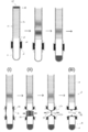
- a specific example of the aspect (2) is shown in FIG.
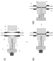
- step (ii) the stretched self-bonding materials are fused by being sandwiched from outside by a crimping means, and in the step (iii), the fused part is cut by a cutting means.
- a specific example of the above (4) is shown in FIG. (5)
- the crimping means comprises a pair of crimping members
- the cutting means is prepared in a mode in which a flat cutting blade is provided in one member of the pair of crimping members so as to be able to pass through, and cutting of the fused portion in the step (iii) is performed,
- a specific example of the above (5) is shown in FIG.
- the self-fusing material is an isobutylene-isoprene copolymer, ethylene-propylene-diene copolymer, polyisobutylene, paraffin, polyvinyl acetate, polyurethane, polydimethylsiloxane, ethylene propylene copolymer, hydrogel polymer, (meth) acrylic acid ester copolymer, The method according to any one of (1) to (6), which is selected from the group consisting of silicone rubber and natural rubber.
- thermoplastic resin having a glass transition temperature of 50 ° C to 180 ° C.
- thermoplastic resin is selected from the group consisting of polyvinyl chloride, vinyl chloride-vinyl acetate copolymer, vinyl chloride-acrylic acid ester copolymer, polyvinylidene chloride, vinylidene chloride-acrylic acid ester copolymer.
- the container-like structure in the above (1) to (9) when used as a container for operating the target substance, the container-like structure may be described as an operation container.
- An operation container for subjecting a sample containing a target component to a predetermined operation inside, an operation unit having at least one open end for subjecting a sample containing the target component to a predetermined operation, and the operation unit A recovery portion having an open end communicating with the open end of the operation portion, and a self covering and integrally connecting an outer surface of the open end portion of the operation portion and the recovery portion.
- the operation container is separated from the operation container by splitting the open portion of the operation portion, the open end of the operation portion being closed by a self-bonding material and including one of the divided contents, and the open end of the recovery portion.
- a method for dividing a substance accommodated in an operation container which is subjected to a step of dividing the material into a divided structure including the other of the divided inclusions including the target object and sealed with a self-bonding material.
- FIG. (13) The method according to (10), wherein the operation medium is a droplet encapsulating medium and an encapsulated aqueous droplet.
- FIG. (14) The operation unit is a sample supply unit for supplying a sample into the operation container and is closed so as to be openable. After the step of supplying the sample, until the end of the step (iii), The method according to (12) or (13), wherein the container is kept in a completely sealed state.
- An operation container for subjecting a sample containing a target component to a predetermined operation inside, An operation unit for subjecting a sample containing the target component to a predetermined operation, a recovery unit for recovering a target object from the operation unit, and an outer surface of the opening end portion of the operation unit and the recovery unit are integrally covered
- the self-fusing material is an isobutylene-isoprene copolymer, ethylene-propylene-diene copolymer, polyisobutylene, paraffin, polyvinyl acetate, polyurethane, polydimethylsiloxane, ethylene propylene copolymer, hydrogel polymer, (meth) acrylic acid ester copolymer,
- the operation container according to any one of (15) to (20) which is selected from the group consisting of silicone rubber and natural rubber.
- the operation container according to any one of (15) to (20), wherein the self-bonding material is a thermoplastic resin having a glass transition temperature of 50 ° C to 180 ° C.
- thermoplastic resin is selected from the group consisting of polyvinyl chloride, vinyl chloride-vinyl acetate copolymer, vinyl chloride-acrylic acid ester copolymer, polyvinylidene chloride, vinylidene chloride-acrylic acid ester copolymer. container.
- a device for operating a target component in an operation container (19) The operation container according to any one of (23), Magnetic particles to capture and transport the target component; A magnetic field applying unit capable of moving the magnetic particles from the operation unit into the recovery unit by applying a magnetic field to the operation container.
- the contents accommodated in the same space in the container-like structure for example, the operation medium for performing physical, chemical and / or biochemical treatment, and the recovery liquid containing the target object
- the container-like structure for example, the operation medium for performing physical, chemical and / or biochemical treatment, and the recovery liquid containing the target object
- segmentation method of this invention is shown.
- FIG. 5 shows a modification of the dividing mechanism in FIG. 4.
- FIG. shows another example of the dividing method of the present invention.
- the example which implements the method of this invention using the device using an operation tube is shown.
- the example which implements the method of this invention using the device using a plate-shaped container is shown.
- FIGS. 1 and 2 show cross-sectional views of the container-like structure.
- the first container part a and the second container part b are bonded by the self-bonding material X.
- the self-bonding material X By combining the first container part a and the second container part b with the self-bonding material X, one container is formed as a whole, and a single container internal space is formed inside.
- the shape of the container formed by the combination of the first container part a and the second container part b is not particularly limited.
- it may be a blind tube as shown in FIGS. 1 (1-1) and (1-2), a deformed rectangular shape as shown in FIG. 2 (1), or other shapes. It may be.
- the first container part a has at least an open end 11a
- the second container part b has an open end 11b corresponding to the open end 11a, and these open ends are coupled to each other.
- the first container part a and the second container part b (illustrated in FIGS. 1 (2) and 2 (2)) before joining may be prepared by forming each separately, It may be prepared by cutting a rectangular or other shaped container.
- the second container part b may be a container having an open end 11b that matches the open end 11a of the capillary.
- FIG. 1 (2) not only what is illustrated in FIG. 1 (2) but also any shape can be adopted.
- the first container part a and the second container part b have the opening ends 11a and 11b close to, in contact with, or fitted to each other, and the opening end 11a in the state of close to, contact with or fitting to each other It can be combined by providing a layer of self-bonding material X so as to cover both of 11b. Thereby, the opening end 11a of the 1st container part a and the opening end 11b of the 2nd container part b connect, and form a single space. As shown in FIGS. 1 (2) and 2 (2), the first container part a has an open end 12 in addition to the open end 11a that contributes to the coupling. Is acceptable.
- the second container part b is a part for collecting the necessary target substance without touching the outside air by the dividing method of the present invention, in addition to the open end 11b that contributes to the above-mentioned connection, it is normal. Does not have an open open end.
- the 2nd container part b is a shape as shown in FIG.1 (2), the end 13 on the opposite side to the opening end 11b is closed.
- FIG. 1 (1-2) is an example in which a part of the open end is closed so as to be openable.
- FIG. 2 (1) is an example in which all of the open ends are closed so as to be openable.
- a lid 15 that covers the open end 12 can be used. It is preferable that the open end 12 is closed in that a completely closed system can be constructed in the container-like structure 1.
- the material of the first container part and the second container part is not particularly limited.
- ABS resin acrylonitrile butadiene copolymer
- AS resin acrylonitrile styrene copolymer
- acrylic resin polyvinyl acetate
- polyethylene terephthalate examples thereof include resin materials such as cyclic polyolefin.
- ceramic, glass, silicone, metal, etc. may be sufficient.
- the materials of the first container part and the second container part may be the same or different from each other.
- Contained items are contained in the formed container internal space.
- the form of the accommodation is not particularly limited, and can be appropriately determined by those skilled in the art according to the use of the structure.
- one or more kinds of the contained materials are arbitrarily selected from the group consisting of a liquid, a solid, a gas, and a dispersion system.
- the container-like structure 1 in the present invention can be used as a container for operating a target substance inside the structure.
- a container-like structure when used as a container for operating a target substance may be particularly described as an operation container.
- a container-like structure 1 (operation container 1) as an operation container includes an operation section (referred to as an operation section A) including a first container section a (operation container section a) and an accommodation thereof, It is comprised from the collection
- the operation container 1 may have a sample supply unit for supplying a sample containing a target component to be operated from the outside.
- the sample supply unit may be the open end 12 in the first container part a. As already described, the open end 12 may be open or may be closed so as to be openable from the viewpoint of sealing.
- the contents inside the operation container 1 include an operation medium serving as a place of operation where the target component is to be provided.
- the operation medium for example, if the operation container 1 is tubular as illustrated in FIGS. 1 (1-1) and (1-2), the operation medium includes an aqueous liquid layer 3l and gel layers 3g and 2g in the longitudinal direction. Examples of the layered product are alternately stacked.
- the operation vessel 1 is a chromatography column (which can have the shape illustrated in FIG. 1 (1-1))
- examples of the operation medium include a chromatography filler and a developing solvent 3c. Further, for example, if the operation container 1 has the shape illustrated in FIG.
- the container contains the droplet encapsulating medium 5, the aqueous droplet 3 d enclosed thereby, and the aqueous droplet 3 d ′ held thereby. Can be mentioned. Details of the contents of the operation container 1 will be described in item 4 described later.
- the self-bonding material is easily deformed by being in a semi-solid state, and has a property of self-mixing and adhering to each other (self-bonding property).
- a substance Due to such properties, the self-bonding material can be filled even in a slight gap, and can adhere to the object without any gap without using an adhesive or an adhesive. Therefore, the self-bonding material can seal the opening end by being in close contact with the opening end.
- the self-bonding property may be exhibited, for example, at normal temperature (for example, 20 ° C. ⁇ 15 ° C.), or may be exhibited by heating (for example, 50 to 180 ° C. or 50 to 150 ° C.). Good.
- the self-bonding material is well known to those skilled in the art and is not particularly limited.
- self-bonding materials are isobutylene-isoprene copolymer (butyl rubber), ethylene-propylene-diene copolymer, polyisobutylene, paraffin, polyvinyl acetate, polyurethane, polydimethylsiloxane, ethylene propylene copolymer, hydrogel polymer, (meth) acrylic It can be selected from the group consisting of acid ester copolymers (which may be in the form of (meth) acrylic adhesives and acrylic foams), silicone rubbers and natural rubbers. These self-bonding materials can be used alone or in combination.
- the above self-bonding material is preferable in that it can have self-bonding properties at room temperature.
- it is preferable to use, for example, an isobutylene-isoprene copolymer among the above-mentioned self-bonding materials.
- thermoplastic resins having a glass transition temperature of 50 to 180 ° C. or 50 to 150 ° C.
- thermoplastic resins include polyethylene, polypropylene, polystyrene, ethylene vinyl acetate copolymer, polyacetal, polymethyl methacrylate, polyvinyl alcohol, polyvinyl chloride, vinyl chloride-vinyl acetate copolymer, vinyl chloride-acrylic acid ester copolymer, polychlorinated. It may be selected from the group consisting of vinylidene and vinylidene chloride-acrylic acid ester copolymers.
- These self-bonding materials can be used alone or in combination. Further, it may be appropriately combined with the substances having the self-bonding property at the normal temperature described above.
- the self-bonding material X is formed on the surface of the container-like structure 1 so as to simultaneously cover both the opening 11a of the first container part a and the opening 11b of the second container part b.
- Layers are formed.
- a layer can be formed by preparing a tape-like self-bonding material, winding it around the joint between the first container part a and the second container part b, and integrating them by self-bonding.
- the thickness of the layer of the self-bonding material is not particularly limited as long as the division method of the present invention can be achieved to some extent, and the required degree varies depending on the outer peripheral length of the container structure to be covered by the layer.
- the self-bonding material layer may be 0.01 to 5 mm, or 0.1 to 5 mm per square centimeter of opening area.
- the thickness of the self-bonding material layer may be 0.001 to 3 mm, or 0.1 to 0.5 mm.
- the layer of the self-bonding material can be formed by dissolving the self-bonding material in a volatile organic solvent and applying the solution to the target portion of the container.
- a volatile organic solvent for example, butyl rubber dissolves in various volatile organic solvents such as toluene, xylene, tetrahydrofuran and the like, and has a high viscosity at a high concentration. Therefore, the formation of a self-bonding material layer by coating can be performed with good reproducibility. After drying, it exhibits the same self-bonding property as the taping method.
- a protective member 16 for protecting the self-fusion material X is further provided on the outer surface of the self-fusion material X that connects the first container portion a and the second container portion b.
- the protective member can be provided for the purpose of preventing contamination of the surface of the self-bonding material and preventing cold flow, which is a unique phenomenon of the self-bonding material. Further, when a plurality of containers are assembled, the containers are also prevented from adhering to each other when the self-bonding material portions touch each other. Any material can be used for the protective member as long as it can achieve such a purpose.
- the self-bonding material can be covered by using a thin film that can be easily broken as a protective member and sticking it to the surface of the self-bonding material.
- a thin film that can be easily broken as a protective member and sticking it to the surface of the self-bonding material.
- Specific examples of such thin films include wafers, paper, resin thin films, metal thin films represented by aluminum foil, and the like.
- the thin film may be provided with a break guide line (perforation) so as to break at a desired position.
- the container structure itself having the container is divided.
- the structure is obtained by performing the step (i) extension of the self-bonding material, the step (ii) division of the contents, and the step (iii) separation of the first container part and the second container part.
- Split. 3 and 4 schematically show the steps of the dividing method of the present invention.
- step (i) as illustrated in FIG. 3 (i) or FIG. 4 (i), the first container part a and the second container part b are separated to form a gap between the two container parts. Cause it to occur.
- the first container part a and the second container part b can be easily pulled apart by pulling one of them or pulling them in opposite directions.
- the self-bonding material X extends.
- the self-bonding material X is further covered with the protective member 16
- the self-bonding material X extends and the protective member 16 is torn by separating both the container portions a and b. From the tear of the protective member 16, the surface of the extended self-bonding material X having high self-bonding property is exposed. That is, the self-bonding property of the surface can be improved by extending the self-bonding material in the step (i).
- the stretched film of the self-bonding material X also maintains a state of completely isolating the space inside the container including the gap formed between the container parts a and b and the external atmosphere.
- the space in the container including the gap formed between the two container parts is divided according to the present invention, but there is no particular limitation on what is allowed as the accommodated material accommodated in the space. And any one selected from the group consisting of a gas and a dispersion system. In the method of the present invention, it is possible to divide the substance without leaking it to the outside, regardless of what kind of substance is contained in the part to be divided.
- step (i) when performing step (i), if the operating environment temperature does not reach the temperature that exhibits the self-bonding property of the self-bonding material (especially when a thermoplastic resin is used), self-bonding can be performed as appropriate. Heating to a suitable temperature may be performed.
- step (ii) the self-bonding materials having exposed surfaces having high self-bonding properties are fused together by stretching.
- the contents are divided by blocking the space between the first container part a and the second container part b, and dividing the single container internal space.
- the method is not particularly limited as long as it can be used.
- the first container part a and the second container part b are twisted about the direction in which they are separated (for example, once or twice).
- the first container part a and the self-fusing surfaces of the self-bonding material X between the container parts a and b are kinked and self-fused in the kinked state.
- the space between the second container part b is completely closed. Thereby, the accommodation of a container-like structure is divided into two.
- the surfaces of the self-bonding material X between the first container part a and the second container part b having high self-bonding properties It is also possible to form a pressure-bonding surface by sandwiching from the outside.
- the first container portion a is obtained by crimping and bonding the surfaces having high self-bonding properties of the self-bonding material X using the two pressure bonding members 31.
- the space between the second container part b is completely closed. Thereby, the accommodation of a container-like structure is divided into two.
- step (iii) the fused part of the self-fusing material is cut.
- the self-bonded portion of the self-bonding material X between the container portions a and b is cut off. Can do. In this case, if the two container parts are further pulled apart while twisting, they can be easily threaded.
- the self-fused portion (crimp surface) of the self-fused material X between the container parts a and b using the cutting means 32 is used. Can be cut. In this case, it is preferable to cut the approximate center of the crimping surface.
- the cutting means 32 is prepared separately from the crimping member 31. That is, each can be used separately as a means or member having a separate function (either cutting or crimping).
- the cutting means is prepared together with the pressure bonding member, so that both functions of cutting and pressure bonding can be provided.
- FIG. 5 A specific example is shown in FIG.
- the cutting means 32 in the dividing mechanism illustrated in FIG. 5 is accommodated in a state in which a part including the cutting end 42 in the cutter body 41 is slidable in the one crimping member 31L, and is opposite to the cutting end 42.
- a pressure head 43 is provided at the end.
- a spring 44 is provided between the pressure head 43 and the crimping member 31L.
- the other crimping member 31 ⁇ / b> R is formed with a recess 45 that can receive the cut end 42.
- the self-bonding material X is extended by the step (i) (FIG. 5 (i)), and the pressure member 32L is pressed in the direction of the arrow in the step (ii) by pressing the pressure head 32. And 31R sandwich the extended self-bonding material X to form a crimped surface (FIG. 5 (ii)).
- step (iii) by further pressing the pressure head 43, the cutter body 41 slides in the pressure-bonding member 31L, and the cut end 42 reaches the pressure-bonding surface of the self-bonding material X, and cuts it. Then, it reaches the recess 45 of the crimping member 31R (FIG. 5 (iii)).
- the container-like structure can be divided by a simple operation of pushing in one direction. Further, since the dividing mechanism illustrated in FIG. 5 is simple by simply pushing and cutting, the mechanism can be miniaturized. Therefore, for example, even when a plurality of container-like structures are integrated in a series or matrix form, it is possible to process a plurality of structures together in a single operation.
- the divided structure can be obtained from the container-like structure with the cut surface completely closed. Specifically, as shown in FIGS. 3 (iii), 4 (iii), and 5 (iii), one end 11a of the first container portion a is closed and divided by the self-bonding material Xa.
- the divided structure including one of the stored items and the divided structure including the other of the divided items in which the second container portion b is sealed at the open end 11b by the self-bonding material Xb are obtained. .
- both ends 11a and 11b generated by the division are completely sealed at the same time by the stretched film of the self-bonding material.
- the contents do not leak or slide off, and in the divided structure on the second container part b side, the contained objects are completely sealed. Yes.
- a part of the container-like structure can be separated without bringing the contents to be collected into contact with the external atmosphere.
- the membrane of the self-bonding material Xb is punctured with a micropipette tip 21 having a thin tip or an injection needle, and the contained material is sucked out.
- the object can be reliably taken out without being brought into contact with the external atmosphere or in a safe place.
- FIG. 6 shows a further modification of the present invention.
- the embodiment of FIG. 6 applies the embodiment of FIG. 4 and provides two locations to be connected (container part a and container part b, and container part b and container part c).
- This aspect is useful in that a band that becomes undesirably broad as the column retention time becomes longer can be collected in a sharp state.
- FIG. 6 illustrates an embodiment in which cutting is performed by the method illustrated in FIG. 3, naturally, the cutting may be performed by the cutting mechanism illustrated in FIGS. 4 and 5.
- Containment of container-like structure It does not specifically limit as what should be accommodated in a container-like structure, 1 type or multiple types are arbitrarily selected from the group which consists of a liquid, solid, gas, and a dispersion system.
- the liquid may be an aqueous liquid or a non-aqueous liquid.
- the dispersion medium and dispersoid to be combined may be solid, liquid, or gas, respectively.
- Specific examples of the dispersion system include gels (regardless of hydrogels and oil gels), sols, and slurries of column fillers and developing solvents.
- the container-like structure of the present invention can be preferably used for subjecting the target component to operation therein. That is, the container-like structure of the present invention is used as an operation container.
- the target component is not particularly limited as long as it is a component that can be operated in a liquid, a solid, a gas, and a dispersion system. Therefore, regardless of whether it is a natural product or a non-natural product, any in vivo component or non-in vivo component can be used.
- the thing to be accommodated in the operation container includes an operation medium that serves as an operation place where the target component is to be provided.
- the operation of the target component includes subjecting the target component to processing in the above-described accommodation and transporting the target component in the accommodation.
- Processes to which the target component is provided include those involving substance changes in the target component (for example, chemical reactions and biochemical reactions) and those involving physical changes (for example, denaturation, dissolution, mixing, emulsification of the target component, and Dilution etc.). By these processes, steps such as extraction, purification, synthesis, elution, separation, recovery and analysis of the target component can be performed.
- processing such as nucleic acid extraction, nucleic acid washing, nucleic acid release, and nucleic acid amplification reaction can be performed using nucleic acid in a nucleic acid-containing sample (tissue, body fluid, excrement, etc.) as a target component it can.
- a nucleic acid-containing sample tissue, body fluid, excrement, etc.
- the operation medium for example, when the operation container is a chromatography column (which may have the shape illustrated in FIG. 1 (1-1)), a chromatography packing material and a developing solvent (hereinafter simply referred to as the operation medium). May be described as a chromatographic filler).
- the chromatography filler 3c can be accommodated in the operation container part a.
- the filter 3s can be accommodated so as to be positioned at the lower end of the chromatography filler 3c.
- nothing may be stored in the collection container b, or a liquid to be mixed with the fraction containing the target component may be stored.
- the packing material for chromatography include ODS for reverse phase and gel filtration carrier, but are not limited thereto, and can be appropriately selected by those skilled in the art.
- the developing solvent and the recovery liquid are also appropriately selected by those skilled in the art.
- Examples of the operation medium include a multilayered structure in which an aqueous liquid layer and a gel layer are alternately stacked in the longitudinal direction. More specifically, the lowest layer of the multi-layered material accommodated in the operation container part a is usually the gel layer 2, and the liquid layer 3l and the gel layer 3g are alternately stacked thereon.
- the container 4 in the collection container part b may be an aqueous liquid or a gel.
- nucleic acid-based liquid As the water-based liquid, those skilled in the art can appropriately select what is necessary for performing the above treatment.
- a nucleic acid extract, a nucleic acid washing solution, a nucleic acid release solution, and a nucleic acid amplification reaction solution can be mentioned.
- the gel layer has a role as a plug (gel plug) that fixes the aqueous liquid in a predetermined position in the tube by sandwiching the aqueous liquid from both sides in the longitudinal direction of the tube.
- the gel is made of a chemically inert substance that is insoluble or hardly soluble in the liquid constituting the aqueous liquid layer when it is overlaid with the aqueous liquid in the tube.
- Insoluble or hardly soluble in a liquid means that the solubility in the liquid at 25 ° C. is approximately 100 ppm or less.
- Gels include both organogels and hydrogels.
- organogel a gel prepared by adding a gelling agent to a liquid substance that is usually water-insoluble or hardly water-soluble can be used.
- water-insoluble or hardly water-soluble liquid substance oil having a solubility in water at 25 ° C. of approximately 100 ppm or less and liquid at room temperature (25 ° C. ⁇ 15 ° C.) is used.
- 1 type, or 2 or more types from the group which consists of liquid fats and oils, ester oil, hydrocarbon oil, and silicone oil may be used.
- the gelling agent an oil gelling agent selected from the group consisting of hydroxy fatty acid, dextrin fatty acid ester, and glycerin fatty acid ester may be used alone or in combination.
- Examples of the content of the gelling agent added to the liquid substance include 0.1 to 0.5% by weight, 0.5 to 2% by weight, or 1 to 5% by weight of the total weight of the liquid substance. It can be. A person skilled in the art can appropriately determine the gelation method.
- hydrogel one prepared by equilibrium swelling of a hydrogel material in water or an aqueous liquid can be used.
- Hydrogel materials include gelatin, collagen, starch, pectin, hyaluronic acid, chitin, chitosan, alginic acid, and derivatives thereof.
- the DNA hydrogel (P-gel) that provides the environment is suitably prepared by those skilled in the art to have a composition suitable for such processing.
- the above-mentioned multi-layered object can be accommodated in at least the operation container part a.
- magnetic particles may be further contained in the aqueous liquid forming the uppermost layer.
- a substance selected from the group consisting of a liquid, a solid, a gas and a dispersion system) suitable for the recovery of the target component is accommodated in the recovery container part b.
- the inner diameter of the tube constituting the operation tube is, for example, 0.1 mm to 5 mm, preferably 1 to 2 mm from the viewpoint of ensuring good operability, but is not limited thereto.
- the length in the longitudinal direction is, for example, 1 to 30 cm, preferably 5 to 15 cm.
- the above-mentioned multi-layered object is accommodated by forming a desired number of layers in such a sized tube so as to include a gel plug having a thickness of, for example, 1 to 20 mm, preferably 2 to 5 mm.
- the specific gravity of the droplet encapsulating medium 5 provided with the gel-sol transfer function to the above-described water-insoluble or poorly water-soluble liquid substance may be less than 1.
- the aqueous liquid added thereto sinks as a droplet 3d in the droplet encapsulating medium 5 and is accommodated in the container.
- the droplet encapsulating medium 5 can make the droplet movable or non-movable by temperature control with the gel-sol transition temperature as a boundary. Further, by forming a depression on the surface of the gel-state droplet encapsulating medium, it is also possible to place and hold the aqueous liquid droplet 3d ′ in the depression.
- the amount of the aqueous liquid constituting one droplet 3d accommodated in the container is not particularly limited, but is about 0.1 to 20 ⁇ L, for example.
- the amount of the droplet enclosing medium 5 accommodated in the container is not particularly limited as long as it is a sufficient amount that can completely enclose the droplet 3d. Specifically, it is possible to use a droplet encapsulating medium having a droplet capacity of 10 to 10,000 times, or 1,000 to 50,000 times.
- magnetic particles may be further contained in the aqueous droplet 3d 'accommodated in the container.
- the target substance sample liquid 30 containing impurities introduced from the sample supply unit 12 is fractionated by the chromatography filler 3c, and the fraction of the target component is obtained by the filter 3s. It falls in the collection part B through filtration. Since a sealed air layer is present between the filter 3s and the recovered liquid 4, the filtrate drops to some extent in the recovery part, and then stops at a constant amount due to an increase in the internal pressure of the recovery part B. (If the operation unit A and the recovery unit B are separated without using the method of the present invention, the filtrate immediately starts to fall again from the filter due to atmospheric pressure.
- the filtrate is a fraction containing impurities, (It will flow into the collection part B.) Thereafter, as shown in FIGS. 4 (i) to (iii), the filtrate can be recovered by dividing the recovery part B from the column using the method of the present invention.
- the magnetic particles are used to move the target component in the operation container by being accompanied by a small amount of liquid mass accompanying the movement of the magnetic field from the outside of the operation container.
- Magnetic particles usually have chemical functional groups on their surfaces.
- the magnetic particles may be stored in advance in the operation container or may not be stored. If contained in advance operation in the container, for example, the layer 3 g 1 and the top of the aqueous liquid as illustrated in FIG. 7, the liquid water-based liquid which is placed on the droplet encapsulating medium 5g as shown in FIG. 8 As in the case of the droplet 3d ′, the magnetic particles 61 can be included in advance in the aqueous liquid present closest to the sample supply unit. On the other hand, when the magnetic particles are not stored in the operation container in advance, the magnetic particles are supplied into the operation container in a state of being mixed in the sample having the target component.
- the magnetic particle is not particularly limited as long as it is a particle that responds to magnetism, and examples thereof include particles having a magnetic material such as magnetite, ⁇ -iron oxide, and manganese zinc ferrite.
- the magnetic particle has a chemical structure that specifically binds to the target component subjected to the above treatment or reaction, such as amino group, carboxyl group, epoxy group, avidin, biotin, digoxigenin, protein A, protein G, complex
- the surface may be provided with a metal ion or an antibody, and may have a surface that specifically binds to the target component by electrostatic force or van der Waals force. Thereby, the target component to be subjected to the reaction or treatment can be selectively adsorbed to the magnetic particles.
- the hydrophilic group on the surface of the magnetic particles include a hydroxyl group, an amino group, a carboxyl group, a phosphoric acid group, and a sulfonic acid group.
- the magnetic particles can further include various elements appropriately selected by those skilled in the art.
- the surface is covered with particles made of a mixture of a magnetic material and silica and / or anion exchange resin, silica and / or anion exchange resin.
- Preferred examples include magnetic particles, magnetic particles whose surface is covered with gold having a hydrophilic group via a mercapto group, and gold particles containing a magnetic substance and having a hydrophilic group via a mercapto group on the surface. .
- the average particle size of the magnetic particles having a hydrophilic group on the surface may be about 0.1 ⁇ m to 500 ⁇ m. When the average particle size is small, the magnetic particles tend to exist in a dispersed state when released from the magnetic field in the aqueous liquid layer.
- the magnetic field application means brings about the movement of the magnetic field for moving the magnetic particles in the operation container together with the target component.
- a magnetic source such as a permanent magnet (for example, a ferrite magnet or a neodymium magnet) or an electromagnet can be used.
- the magnetic field applying means can aggregate the magnetic particles dispersed in the aqueous liquid layer or droplet in the operation container on the inner wall surface (conveying surface) of the operation container on the outside of the operation container.
- the magnetic particles aggregated in the gel layer or the droplet encapsulating medium in the container can be arranged close to the operation container to such an extent that the particles can be transported in the aggregated state.
- the magnetic field application means can effectively generate a magnetic field for the magnetic particles through the transfer surface of the operation container, and the target component can be captured and transferred together with the magnetic particle lump.
- the magnetic particles can be moved by an external magnetic field operation in the gel and can pass through the gel. This is due to the thixotropic nature of the gel (thixotropic properties). That is, the magnetic particles in the operation container give a shearing force to the gel along the transport surface by moving the magnet from the outside, and the gel in the traveling direction of the magnetic particles is solated and fluidized. You can go forward. In addition, the sol released from the shearing force after the magnetic particles have passed through returns quickly to the gel state, so that the gel does not form through holes due to the passage of the magnetic particles. If this phenomenon is utilized, the object can easily move using the magnetic particles as a carrier, so that, for example, various chemical environments composed of droplets provided with the object can be made in a very short time. Can be switched.
- the cell lysate (containing a surfactant and a chaotropic salt such as guanidine thiocyanate) 3l 1 and the washing solutions 3l 2 to 3l 4 are placed in the operation container part a with gel plugs 3g 1 to 3g 3 and The multi-layered product alternately layered with 2g is accommodated, and the eluate 4 is accommodated in the recovery container part b through the air layer.
- a surfactant and a chaotropic salt such as guanidine thiocyanate
- the operating unit A a biological sample 30 including the target component, subjected to cell lysate 3l 1 operation tube 1 from the sample supply unit 12, to release the nucleic acids from the cells (Fig. 7 (1)).
- the liberated nucleic acid can be specifically adsorbed on the silica surface of the magnetic particles 61.
- the adsorbed nucleic acid cannot be used as a template for gene amplification reaction because it is accompanied by a reaction inhibiting component. Therefore, the magnetic particles remain adsorbed the nucleic acid to the surface is washed with a washing solution 3l 2. At this time, in order to prevent a large amount of reaction-inhibiting components from being introduced into the washing solution, the magnetic particles 61 are collected by the magnet 63 (FIG.
- the nucleic acid is separated from the magnetic particles and eluted in the eluate.
- the magnetic particles from which the nucleic acid has been eluted are kept in the gel plug 2g again, so that the purified purified nucleic acid remains in the recovery portion B (see FIG. 7 (14)).
- the nucleic acid thus obtained is useful as a template nucleic acid that can be analyzed by a nucleic acid amplification reaction.
- the obtained nucleic acid can be recovered in a completely sealed state by removing the recovery part B of the operating tube from the operating part A by the dividing method of the present invention (FIG. 7 (15)).
- the recovered nucleic acid can be subjected to the next operation (step of performing analysis by nucleic acid amplification reaction).
- any of the housing of the operating tube e.g. washing liquid 3l 4 and eluent 4
- the extracted and washed nucleic acid can be amplified by subjecting the nucleic acid amplification solution to an appropriate temperature cycle using an appropriate heating means.
- the amplified nucleic acid can be recovered in a completely sealed state by removing the recovery part B from the operation part A using the dividing method of the present invention.
- the container was filled with, for example, a mixture of, for example, silicone oil and an oil gelling agent (eg, 90 ° C.) so that the filling height was about 3 mm, and the temperature was lowered.
- an oil gelling agent eg, 90 ° C.
- one droplet 3d 1 of the nucleic acid extract, two droplets 3d 2 and 3d 2 of the washing solution, and one PCR reaction solution 3d 4 are placed in oil and left to room temperature.
- the entire oil can be gelled.
- a depression can be formed on the gelled oil surface, and a mixture 3d ′ of a cell lysate containing magnetic silica particles and a nucleic acid-containing biological sample can be placed thereon.
- the end of an alumina ceramic plate (not shown) is separately heated with an electric heater, and when the temperature gradient is stably formed on the plate surface, the container is placed on the plate and allowed to stand. . Thereby, a part of the gel in the container (the left half in FIG. 8) is solated by heat, and both the non-flowable gel 5g and the flowable sol 5s coexist as a droplet encapsulating medium.
- the magnetic force source (magnet) 63 is brought close to the container 1, and the liquid on the droplet encapsulating medium 5g is transferred from the conveying surface side.
- the magnetic particles 61 can be separated in the transport surface direction while the droplet 3d ′ is placed on the droplet encapsulating medium 5g.
- the separated magnetic particles 61 are aggregated by a magnetic force, and the aggregated magnetic particles attract the substance adsorbed thereto and some liquid to the surroundings.
- the child droplet 71b including magnetic particles is separated using the droplet 3d 'as a mother droplet.
- the separated child droplets 71b can pass through the droplet encapsulating medium 5g while collapsing the tertiary structure of the gel according to the induction of the magnetic field, and can settle to the container transport surface.
- the small droplet 71b containing the magnetic particles and the accompanying nucleic acid and other components is moved in the droplet encapsulating medium 5g, and another encapsulated droplet 3d made of a nucleic acid extract is obtained.
- the nucleic acid component contained in the small droplet 71b can be extracted.
- the nucleic acid extracted from the enclosed droplet 71c composed of the nucleic acid extract combined with the small droplet 71b is small droplet.
- 71e is separated along with the magnetic particles and moves into the droplet encapsulating medium 5g.
- the nucleic acid-containing sample, or the small droplet 71f that has undergone the nucleic acid extraction treatment and the washing treatment as necessary, are combined with the droplet 3d 4 made of the nucleic acid amplification reaction solution (FIGS. 8 (f) and (g)).
- a droplet 71g made of a nucleic acid amplification reaction solution containing the nucleic acid to be amplified and the magnetic particles can be obtained. Since droplet encapsulating medium 5s surrounding the droplets 3d 4 is a sol state having fluidity, the entire droplet 71g obtained united with the small droplet 71f is movable.
- the droplet 71g moves to the point of the nucleic acid amplification reaction start temperature in the temperature change region (FIG.
- the nucleic acid amplification reaction can be started.
- the droplet 71i containing the amplification product is moved into the recovery unit B, and the recovery unit B is moved to the operation unit A using the dividing method of the present invention.
- the amplification product can be recovered in a completely sealed state by removing from the container.
Landscapes
- Chemical & Material Sciences (AREA)
- Health & Medical Sciences (AREA)
- Analytical Chemistry (AREA)
- General Health & Medical Sciences (AREA)
- Chemical Kinetics & Catalysis (AREA)
- Clinical Laboratory Science (AREA)
- Biochemistry (AREA)
- General Physics & Mathematics (AREA)
- Immunology (AREA)
- Pathology (AREA)
- Hematology (AREA)
- Dispersion Chemistry (AREA)
- Physics & Mathematics (AREA)
- Life Sciences & Earth Sciences (AREA)
- Mechanical Engineering (AREA)
- Engineering & Computer Science (AREA)
- Packages (AREA)
- Apparatus Associated With Microorganisms And Enzymes (AREA)
- Physical Or Chemical Processes And Apparatus (AREA)
Abstract
Description
特に、本発明は、液体、固体、気体、及び分散系のうち、一種又は複数種を密閉状態で収容した容器状構造体から、収容物或いはその一部を、密閉状態を保持しながら容易に分離・回収する方法、及びその方法に適した容器及びデバイスに関する。
しかしながら、構造体が単なる貯蔵用容器ではなく、分離すべき対象物を、予め物理的、化学的、及び/又は生物学的操作の工程に供するために用いられる容器である場合、構造体は、対象物が上記の操作の場を提供する操作媒体と接触できるよう、対象物と操作媒体との両方を同一容器内に存在させる必要がある。
本発明は、以下の発明を含む。
少なくとも1つの開口端を有する第1の容器部と、前記第1の容器部の開口端と連通する開口端を有する第2の容器部と、前記第1の容器部と前記第2の容器部との前記開口端部分の外表面を覆い一体的に接続する自己融着材とを有し、且つ、物質を収容している容器状構造体を、以下の工程:
(i)前記第1の容器部と前記第2の容器部との間を互いに引き離して前記自己融着材を伸展させる工程、
(ii)伸展した前記自己融着材同士を前記第1の容器部と前記第2の容器部との間を塞ぐように融着させて前記収容物を分割する工程、及び
(iii)前記自己融着材の融着させた部分を切断することによって、前記容器状構造体を、前記第1の容器部の前記開口端が自己融着材によって閉鎖され且つ分割された前記収容物の一方を含む分割構造体と、前記第2の容器部の前記開口端が自己融着材によって密閉され且つ分割された前記収容物の他方を含む分割構造体とに分割する工程
に供する、容器に収容された物質の分割方法。
前記工程(ii)及び前記工程(iii)において、前記第1の容器部と前記第2の容器部とを引き離した方向を軸としてねじることによって、前記伸展させた自己融着材同士の融着及び前記融着させた部分の切断を行う、(1)に記載の方法。
上記(2)の態様の具体例は、図3に示される。
前記工程(ii)において、伸展させた自己融着材同士を、外部から圧着用手段で挟んで融着させ、前記工程(iii)において、前記融着させた部分を、切断手段によって切断する、(1)に記載の方法。
前記圧着用手段と前記切断手段とが別々に用意される、(3)に記載の方法。
上記(4)の具体例は、図4に示される。
(5)
前記圧着用手段が一対の圧着用部材からなり、
前記切断手段が、前記一対の圧着用部材のうちの一方の部材内に平板状切断刃が貫通可能に設けられた態様で用意され、前記工程(iii)における融着させた部分の切断が、前記平板状切断刃を貫通させることによって行われる、(3)に記載の方法。
上記(5)の具体例は、図5に示される。
前記(i)~(iii)の工程に供されるべき前記容器状構造体が、0.001~3mm厚さの前記自己融着材に覆われている、(1)~(5)のいずれかに記載の方法。
(7)
前記自己融着材が、イソブチレン-イソプレンコポリマー、エチレン-プロピレン-ジエンコポリマー、ポリイソブチレン、パラフィン、ポリ酢酸ビニル、ポリウレタン、ポリジメチルシロキサン、エチレンプロピレンコポリマー、ハイドロゲルポリマー、(メタ)アクリル酸エステルコポリマー、シリコーンゴム及び天然ゴムからなる群から選ばれる、(1)~(6)のいずれかに記載の方法。
(8)
前記自己融着材が50℃~180℃のガラス転移温度を有する熱可塑性樹脂である、(1)~(6)のいずれかに記載の方法。
(9)
前記熱可塑性樹脂が、ポリ塩化ビニル、塩化ビニル-酢酸ビニルコポリマー、塩化ビニル-アクリル酸エステルコポリマー、ポリ塩化ビニリデン、塩化ビニリデン-アクリル酸エステルコポリマーからなる群から選ばれる、(8)に記載の方法。
(10)
対象成分を含む試料を内部で所定の操作に供するための操作容器であって、対象成分を含む試料を所定の操作に供するための、少なくとも1つの開口端を有する操作部と、前記操作部からの目的物を回収するための、前記操作部の開口端と連通する開口端を有する回収部と、前記操作部と前記回収部との前記開口端部分の外表面を覆い一体的に接続する自己融着材とを有し、且つ、前記対象成分が供されるべき操作の場となる液体、固体、気体及び分散系からなる群から選ばれる操作媒体を収容している操作容器を、前記試料の所定の操作及び前記目的物の回収に供した後、以下の工程:
(i)前記操作部と前記回収部との間を互いに引き離して前記自己融着材を伸展させる工程、
(ii)伸展した前記自己融着材同士を前記操作部と前記回収部との間を塞ぐように融着させて収容物を分割する工程、及び
(iii)前記自己融着材の融着させた部分を切断することによって、前記操作容器を、前記操作部の前記開口端が自己融着材によって閉鎖され且つ分割された収容物の一方を含む分割構造体と、前記回収部の前記開口端が自己融着材によって密閉され且つ前記目的物を含む分割された収容物の他方を含む分割構造体とに分割する工程
に供する、操作容器に収容された物質の分割方法。
前記操作部がクロマトグラフィー用カラムから構成され、前記操作媒体がクロマトグラフィー用充填剤及び展開溶媒である、(10)に記載の方法。
上記(11)の具体例は、図4に示される。
前記容器状構造体が管状の形状を有し、前記操作媒体が、水系液体層及びゲル層が長手方向に交互に重層された重層物である、(10)に記載の方法。
上記(12)の具体例は、図7に示される。
(13)
前記操作媒体が、液滴封入媒体及び封入された水系液滴である、(10)に記載の方法。
上記(13)の具体例は、図8に示される。
(14)
前記操作部が、前記操作容器内に試料を供給するための試料供給部であって開口可能に閉鎖されたものを有し、前記試料を供給する工程後、前記工程(iii)終了まで、前記収容物の完全密閉状態が保たれる、(12)又は(13)に記載の方法。
対象成分を含む試料を内部で所定の操作に供するための操作容器であって、
対象成分を含む試料を所定の操作に供する操作部と、前記操作部からの目的物を回収する回収部と、前記操作部と前記回収部との前記開口端部分の外表面を覆い一体的に接続する自己融着材とを有し、且つ前記対象成分が供されるべき操作の場となる液体、固体、気体及び分散系からなる群から選ばれる操作媒体を収容している操作容器。
前記自己融着材の外表面に保護部材をさらに有する、(15)に記載の操作容器。
(17)
0.001~3mm厚さの前記自己融着材に覆われている、(15)又は(16)に記載の操作容器。
前記操作部がクロマトグラフィー用カラムから構成され、前記操作媒体がクロマトグラフィー用充填剤及び展開溶媒である、(15)~(17)のいずれかに記載の操作容器。
上記(18)の具体例は、図1(1-1)に示される。
前記操作容器が管状の形状を有し、前記操作媒体が、水系液体層及びゲル層が長手方向に交互に重層された重層物である、(15)~(17)のいずれかに記載の操作容器。
上記(19)の具体例は、図1(1-2)に示される。
(20)
前記操作媒体が、液滴封入媒体及び封入された水系液滴である、(15)~(17)のいずれかに記載の操作容器。
上記(20)の具体例は、図1(2)に示される。
前記自己融着材が、イソブチレン-イソプレンコポリマー、エチレン-プロピレン-ジエンコポリマー、ポリイソブチレン、パラフィン、ポリ酢酸ビニル、ポリウレタン、ポリジメチルシロキサン、エチレンプロピレンコポリマー、ハイドロゲルポリマー、(メタ)アクリル酸エステルコポリマー、シリコーンゴム及び天然ゴムからなる群から選ばれる、(15)~(20)のいずれかに記載の操作容器。
(22)
前記自己融着材が50℃~180℃のガラス転移温度を有する熱可塑性樹脂である、(15)~(20)のいずれかに記載の操作容器。
(23)
前記熱可塑性樹脂が、ポリ塩化ビニル、塩化ビニル-酢酸ビニルコポリマー、塩化ビニル-アクリル酸エステルコポリマー、ポリ塩化ビニリデン、塩化ビニリデン-アクリル酸エステルコポリマーからなる群から選ばれる、(22)に記載の操作容器。
操作容器内で対象成分を操作するためのデバイスであって、
(19)~(23)のいずれかに記載の操作容器と、
対象成分を捕捉し運搬すべき磁性体粒子と、
前記操作容器に磁場を印加することによって前記磁性体粒子を前記操作部内から前記回収部内へ移動させることができる磁場印加手段とを含むデバイス。
本発明によると、容器に複雑な開閉機構を設ける必要がないため製造コストが安くすむ。また、シンプルな機構で容器の一部を分離・回収することができるため、小型化されたデバイスにも対応することができる。
a:第1の容器部
b:第2の容器部
X:自己融着剤
A:操作部
B:回収部
3l:水系液体層
3g、2g:ゲル層
3d:水系液滴
5:液滴封入媒体
11a、11b:開口端
12:開口端(試料供給部)
16:保護部材
31:圧着用部材
32:切断手段
41、42:平板状切断刃(41:カッター本体、42:切断端)
61:磁性体粒子
63:磁場印可手段(磁石)
本発明の容器状構造体の例を図1及び図2に示す。図1及び図2は、容器状構造体の断面図を示している。本発明の容器状構造体1は、第1の容器部aと、第2の容器部bとが自己融着材Xによって結合している。第1の容器部aと、第2の容器部bとが自己融着材Xによって結合することにより、全体として1つの容器を構成し、内部に単一の容器内部空間が形成される。
開口端12が閉鎖されることは、容器状構造体1内に完全閉鎖系を構築することができる点で好ましい。
本発明においては、自己融着材とは、半固体状態で存在することによって容易に変形し、且つ、自己同士が圧接されると互いに混ざり合って融着する性質(自己融着性)を有する物質をいう。このような性質により、自己融着材は僅かな隙間にも充填されることができ、接着剤や粘着材を用いなくとも対象物に隙間無く密着することができる。従って、自己融着材は開口端に密着することによって開口端を密閉することが可能である。
自己融着性は、例えば常温(例えば20℃±15℃)において呈されるものであってもよいし、加熱(例えば50~180℃又は50~150℃)によって呈されるものであってもよい。
自己融着材の層を容器に形成させる手段は、テープ状の自己融着材によるテーピングに限定されない。例えば自己融着材を揮発性有機溶媒に溶かし、その溶液を容器の対象部分に塗布することで自己融着材の層を形成させることができる。例えばブチルゴムはトルエン、キシレン、テトラヒドロフラン等の種々の揮発性有機溶媒に溶解し、高濃度では高粘度になるため、塗布による自己融着材層の形成が再現良く実施できる。乾燥後はテーピングによる方法と同様な自己融着性を発揮する。
本発明においては、容器状構造体の収容物を分割するために、収容物を有する容器状構造体自体を分割する。本発明では、工程(i)自己融着材の伸展、工程(ii)収容物の分割、及び工程(iii)第1の容器部と第2の容器部との切り離しを行うことによって、構造体を分割する。本発明の分割方法の工程を模式的に示した図を図3及び図4に示す。
図3に示す態様の場合、図3(iii)に示すように、さらにねじる(回転させる)ことによって、両容器部a及びb間の自己融着材Xの自己融着した部分をねじ切ることができる。この場合、ねじりながらさらに両容器部間を引き離すようにすると、容易にねじ切ることができる。
一方、図4に示す態様の場合、図4(iii)に示すように、切断手段32を用いて両容器部a及びb間の自己融着材Xの自己融着した部分(圧着面)を切断することができる。この場合、圧着面の凡そ中央を切断するとよい。
一方、その変形態様として、切断手段が圧着用部材とともに用意されることにより、切断と圧着との両機能を備えさせることもできる。その具体例を図5に示す。図5に例示する分割機構における切断手段32は、カッター本体41における切断端42を含む一部が一方の圧着用部材31L内に摺動可能な状態で収容されており、切断端42と反対の端に加圧ヘッド43を有するものである。加圧ヘッド43と圧着用部材31Lとの間にはバネ44が備えられている。他方の圧着用部材31Rには、切断端42を受容可能な凹部45が形成されている。
このように、容器状構造体の一部を、回収すべき収容物を外部雰囲気に接触させることなく分離することができる。
容器状構造体に収容されるべきものとしては特に限定されず、液体、固体、気体及び分散系からなる群から任意に1種又は複数種が選択される。
液体としては、水系液体及び非水系液体を問わない。分散系としては、組み合わせられる分散媒及び分散質はそれぞれ固体、液体及び気体のいずれであってもよい。分散系の具体例として、ゲル(ヒドロゲル及びオイルゲルを問わない)、ゾル、及び、カラム充填剤と展開溶媒とのスラリーなどが挙げられる。
この場合において、対象成分は、液体、固体、気体及び分散系中で操作されうる成分であれば特に限定されない。従って、天然物及び非天然物を問わず、生体内成分及び非生体内成分を問わない。
操作媒体としては、例えば、操作容器がクロマトグラフィー用カラム(図1(1-1)に例示の形状を有しうる)である場合、クロマトグラフィー用充填材剤及び展開溶媒(以下、これらを単にクロマトグラフィー用充填材剤と記載する場合がある)が挙げられる。図1(1-1)に記載のように、クロマトグラフィー用充填材剤3cが操作用容器部aに収容されうる。さらに、クロマトグラフィー用充填材剤3cの下端に位置するようにフィルター3sが収容されうる。回収用容器部bには、図1(1-1)に示すように何も収容されていなくてもよいし、対象成分を含む画分と混合させるべき液体などを収容していてもよい。
クロマトグラフィー用充填剤としては、逆相用ODSやゲル濾過担体などが挙げられるが、これらに限らず、当業者によって適宜選択されることができる。展開溶媒及び回収液も、当業者によって適宜選択される。
操作容器が図1(1-2)に例示の管状のものである場合、操作媒体としては、水系液体層及びゲル層が長手方向に交互に重層された重層物が挙げられる。より具体的には、操作用容器部a中に収容されている重層物の最下層は通常ゲル層2であり、その上に液体層3l及びゲル層3gが交互に重層される。回収用容器部b中の収容物4としては、水系液体であってもよいし、ゲルであってもよい。
オルガノゲルとしては、通常、非水溶性又は水難溶性である液体物質にゲル化剤を添加してゲル化することにより調製されたものが用いられうる。非水溶性又は水難溶性である液体物質としては、25℃における水に対する溶解度が概ね100ppm以下であり、常温(25℃±15℃)において液体状であるオイルが用いられる。たとえば、液体油脂、エステル油、炭化水素油、及びシリコーン油からなる群から1種又は2種以上が組み合わされて用いられうる。ゲル化剤としては、ヒドロキシ脂肪酸、デキストリン脂肪酸エステル、及びグリセリン脂肪酸エステルからなる群から選ばれる油ゲル化剤が1種又は2種以上組み合わされて用いられうる。
ヒドロゲルが、上記の水系液体と同様に対象成分が供される処理の環境を提供するものである場合(一例として、対象成分がタンパク質合成用基質である場合に、その対象成分からタンパク質を得る反応環境を提供するDNAヒドロゲル(P-ゲル))は、そのような処理に適した組成を有するように当業者によって適宜調製される。
また、操作容器が図1(2)に例示の形状である場合、上述の非水溶性又は水難溶性である液体物質にゲルーゾル転移機能を与えられた液滴封入媒体5の比重が1未満であれば、そこに加えられた水系液体は液滴封入媒体5に液滴3dとして沈み、容器内に収容される。液滴封入媒体5は、ゲル-ゾル転移温度を境として、温度制御で液滴を、移動可能な又は移動不可能な状態にすることができる。また、ゲル状態の液滴封入媒体には、その表面に窪みを形成することによって、その窪みに水系液体の液滴3d’を載せて保持することも可能である。
容器内に収容される液滴封入媒体5の量は、液滴3dを完全に封入することができる十分量であれば特に限定されない。具体的には、液滴の容量の1,0~10,000倍、或いは1,000~50,000倍の液滴封入媒体を用いることができる。
[5-1.クロマトグラフィー用カラムの場合]
図4に示すように、操作部Aにおいては、試料供給部12から投入された不純物を含む対象物質試料液30がクロマトグラフィー用充填剤3cにより分画され、対象成分の画分がフィルター3sによる濾過を経て回収部B内に落ちる。フィルター3sと回収液4との間には密封状態の空気層が存在しているため濾液はある程度回収部に落ちた後、回収部B内圧の上昇によって一定量で止まる。(もし、本発明の方法によらずに操作部Aと回収部Bとを分断すると、大気圧により、フィルターから再び濾液が直ちに落ち始める。この濾液が不純物を含む画分であると、不純物が回収部B内に流れ込んでしまう。)
その後、図4(i)~(iii)に示すように、本発明の方法を用いてカラムから回収部Bを分割することによって濾液を回収することができる。
以下、操作容器のうち操作管を用いたデバイス(キャピラリ状マイクロデバイス)及び矩形状(又は変形矩形状)容器を用いたデバイス(液滴操作デバイス)について述べる。いずれのデバイスも、対象成分を磁性体粒子に吸着させ、操作容器外部から磁場印加手段を用いて磁場を変動させることによって、対象成分の捕捉・運搬などの操作を行うことができる。
一方、磁性体粒子が予め操作容器内に収容されていない場合は、対象成分を有する試料中に混合された状態で操作容器内に供給される。
磁性体粒子が表面に有する親水性基としては、水酸基、アミノ基、カルボキシル基、リン酸基、スルホン酸基等が挙げられる。
操作管を用いた使用例として、核酸を対象成分として含む生体試料を、操作管内で核酸抽出及び洗浄を行う方法(図7)を以下に挙げる。当業者であれば、以下の例を参考にして、核酸以外の対象成分を所望の操作に供する手段を適宜選択することができる。
図7の操作管においては、操作用容器部aに、細胞溶解液(界面活性剤とグアニジンチオシアネート等のカオトロピック塩とを含む)3l1及び洗浄液3l2~3l4がゲルプラグ3g1~3g3及び2gと交互に重層された重層物収容され、空気層を介して、回収用容器部bに溶出液4が収容されている。
液滴操作デバイスの例として、核酸を対象成分として含む生体試料を、操作管内で核酸抽出、洗浄及び核酸増幅を行う方法(図8)を以下に挙げる。当業者であれば、以下の例を参考にして、核酸以外の対象成分を所望の操作に供する手段を適宜選択することができる。
核酸増幅反応が終了した後は、図8(i)に示すように、増幅産物を含む液滴71iが回収部B内へ移動され、本発明の分割方法を用いて回収部Bを操作部Aから取り外すことによって増幅産物を完全密閉状態で回収することができる。
Claims (24)
- 少なくとも1つの開口端を有する第1の容器部と、前記第1の容器部の開口端と連通する開口端を有する第2の容器部と、前記第1の容器部と前記第2の容器部との前記開口端部分の外表面を覆い一体的に接続する自己融着材とを有し、且つ、物質を収容している容器状構造体を、以下の工程:
(i)前記第1の容器部と前記第2の容器部との間を互いに引き離して前記自己融着材を伸展させる工程、
(ii)伸展した前記自己融着材同士を前記第1の容器部と前記第2の容器部との間を塞ぐように融着させて前記収容物を分割する工程、及び
(iii)前記自己融着材の融着させた部分を切断することによって、前記容器状構造体を、前記第1の容器部の前記開口端が自己融着材によって閉鎖され且つ分割された前記収容物の一方を含む分割構造体と、前記第2の容器部の前記開口端が自己融着材によって密閉され且つ分割された前記収容物の他方を含む分割構造体とに分割する工程
に供する、容器に収容された物質の分割方法。 - 前記工程(ii)及び前記工程(iii)において、前記第1の容器部と前記第2の容器部とを引き離した方向を軸としてねじることによって、前記伸展させた自己融着材同士の融着及び前記融着させた部分の切断を行う、請求項1に記載の方法。
- 前記工程(ii)において、伸展させた自己融着材同士を、外部から圧着用手段で挟んで融着させ、前記工程(iii)において、前記融着させた部分を、切断手段によって切断する、請求項1に記載の方法。
- 前記圧着用手段と前記切断手段とが別々に用意される、請求項3に記載の方法。
- 前記圧着用手段が一対の圧着用部材からなり、
前記切断手段が、前記一対の圧着用部材のうちの一方の部材内に平板状切断刃が貫通可能に設けられた態様で用意され、前記工程(iii)における融着させた部分の切断が、前記平板状切断刃を貫通させることによって行われる、請求項3に記載の方法。 - 前記(i)~(iii)の工程に供されるべき前記容器状構造体が、0.001~3mm厚さの前記自己融着材に覆われている、請求項1~5のいずれか1項に記載の方法。
- 前記自己融着材が、イソブチレン-イソプレンコポリマー、エチレン-プロピレン-ジエンコポリマー、ポリイソブチレン、パラフィン、ポリ酢酸ビニル、ポリウレタン、ポリジメチルシロキサン、エチレンプロピレンコポリマー、ハイドロゲルポリマー、(メタ)アクリル酸エステルコポリマー、シリコーンゴム及び天然ゴムからなる群から選ばれる、請求項1~6のいずれか1項に記載の方法。
- 前記自己融着材が50℃~180℃のガラス転移温度を有する熱可塑性樹脂である、請求項1~6のいずれか1項に記載の方法。
- 前記熱可塑性樹脂が、ポリ塩化ビニル、塩化ビニル-酢酸ビニルコポリマー、塩化ビニル-アクリル酸エステルコポリマー、ポリ塩化ビニリデン、塩化ビニリデン-アクリル酸エステルコポリマーからなる群から選ばれる、請求項8に記載の方法。
- 対象成分を含む試料を内部で所定の操作に供するための操作容器であって、対象成分を含む試料を所定の操作に供するための、少なくとも1つの開口端を有する操作部と、前記操作部からの目的物を回収するための、前記操作部の開口端と連通する開口端を有する回収部と、前記操作部と前記回収部との前記開口端部分の外表面を覆い一体的に接続する自己融着材とを有し、且つ、前記対象成分が供されるべき操作の場となる液体、固体、気体及び分散系からなる群から選ばれる操作媒体を収容している操作容器を、前記試料の所定の操作及び前記目的物の回収に供した後、以下の工程:
(i)前記操作部と前記回収部との間を互いに引き離して前記自己融着材を伸展させる工程、
(ii)伸展した前記自己融着材同士を前記操作部と前記回収部との間を塞ぐように融着させて収容物を分割する工程、及び
(iii)前記自己融着材の融着させた部分を切断することによって、前記操作容器を、前記操作部の前記開口端が自己融着材によって閉鎖され且つ分割された収容物の一方を含む分割構造体と、前記回収部の前記開口端が自己融着材によって密閉され且つ前記目的物を含む分割された収容物の他方を含む分割構造体とに分割する工程
に供する、操作容器に収容された物質の分割方法。 - 前記操作部がクロマトグラフィー用カラムから構成され、前記操作媒体がクロマトグラフィー用充填剤及び展開溶媒である、請求項10に記載の方法。
- 前記容器状構造体が管状の形状を有し、前記操作媒体が、水系液体層及びゲル層が長手方向に交互に重層された重層物である、請求項10に記載の方法。
- 前記操作媒体が、液滴封入媒体及び封入された水系液滴である、請求項10に記載の方法。
- 前記操作部が、前記操作容器内に試料を供給するための試料供給部であって開口可能に閉鎖されたものを有し、前記試料を供給する工程後、前記工程(iii)終了まで、前記収容物の完全密閉状態が保たれる、請求項12又は13に記載の方法。
- 対象成分を含む試料を内部で所定の操作に供するための操作容器であって、
対象成分を含む試料を所定の操作に供する操作部と、前記操作部からの目的物を回収する回収部と、前記操作部と前記回収部との前記開口端部分の外表面を覆い一体的に接続する自己融着材とを有し、且つ前記対象成分が供されるべき操作の場となる液体、固体、気体及び分散系からなる群から選ばれる操作媒体を収容している操作容器。 - 前記自己融着材の外表面に保護部材をさらに有する、請求項15に記載の操作容器。
- 0.001~3mm厚さの前記自己融着材に覆われている、請求項15又は16に記載の操作容器。
- 前記操作部がクロマトグラフィー用カラムから構成され、前記操作媒体がクロマトグラフィー用充填剤及び展開溶媒である、請求項15~17のいずれか1項に記載の操作容器。
- 前記操作容器が管状の形状を有し、前記操作媒体が、水系液体層及びゲル層が長手方向に交互に重層された重層物である、請求項15~17のいずれか1項に記載の操作容器。
- 前記操作媒体が、液滴封入媒体及び封入された水系液滴である、請求項15~17のいずれか1項に記載の操作容器。
- 前記自己融着材が、イソブチレン-イソプレンコポリマー、エチレン-プロピレン-ジエンコポリマー、ポリイソブチレン、パラフィン、ポリ酢酸ビニル、ポリウレタン、ポリジメチルシロキサン、エチレンプロピレンコポリマー、ハイドロゲルポリマー、(メタ)アクリル酸エステルコポリマー、シリコーンゴム及び天然ゴムからなる群から選ばれる、請求項15~20のいずれか1項に記載の操作容器。
- 前記自己融着材が50℃~180℃のガラス転移温度を有する熱可塑性樹脂である、請求項15~20のいずれか1項に記載の操作容器。
- 前記熱可塑性樹脂が、ポリエチレン、ポリプロピレン、ポリスチレン、エチレン酢酸ビニルコポリマー、ポリアセタール、ポリメチルメタクリレート、ポリビニルアルコール、ポリ塩化ビニル、塩化ビニル-酢酸ビニルコポリマー、塩化ビニル-アクリル酸エステルコポリマー、ポリ塩化ビニリデン、塩化ビニリデン-アクリル酸エステルコポリマーからなる群から選ばれる、請求項22に記載の操作容器。
- 操作容器内で対象成分を操作するためのデバイスであって、
請求項19~23のいずれか1項に記載の操作容器と、
対象成分を捕捉し運搬すべき磁性体粒子と、
前記操作容器に磁場を印加することによって前記磁性体粒子を前記操作部内から前記回収部内へ移動させることができる磁場印加手段とを含むデバイス。
Priority Applications (3)
| Application Number | Priority Date | Filing Date | Title |
|---|---|---|---|
| US14/126,838 US10589191B2 (en) | 2011-06-24 | 2012-05-31 | Method for separating substance accommodated in vessel |
| JP2013521513A JP5741872B2 (ja) | 2011-06-24 | 2012-05-31 | 容器に収容された物質の分割方法 |
| CN201280030273.XA CN103619727B (zh) | 2011-06-24 | 2012-05-31 | 容纳于容器内的物质的分割方法 |
Applications Claiming Priority (2)
| Application Number | Priority Date | Filing Date | Title |
|---|---|---|---|
| JP2011141140 | 2011-06-24 | ||
| JP2011-141140 | 2011-06-24 |
Publications (1)
| Publication Number | Publication Date |
|---|---|
| WO2012176598A1 true WO2012176598A1 (ja) | 2012-12-27 |
Family
ID=47422438
Family Applications (1)
| Application Number | Title | Priority Date | Filing Date |
|---|---|---|---|
| PCT/JP2012/064065 Ceased WO2012176598A1 (ja) | 2011-06-24 | 2012-05-31 | 容器に収容された物質の分割方法 |
Country Status (4)
| Country | Link |
|---|---|
| US (1) | US10589191B2 (ja) |
| JP (1) | JP5741872B2 (ja) |
| CN (1) | CN103619727B (ja) |
| WO (1) | WO2012176598A1 (ja) |
Cited By (3)
| Publication number | Priority date | Publication date | Assignee | Title |
|---|---|---|---|---|
| US9623410B2 (en) | 2012-03-30 | 2017-04-18 | Shimadzu Corporation | Segmentable container and method of segmenting substance contained in container |
| JP2017127224A (ja) * | 2016-01-19 | 2017-07-27 | 株式会社島津製作所 | 核酸前処理キット、および塩基配列解析方法 |
| JP2020168027A (ja) * | 2020-07-14 | 2020-10-15 | 株式会社島津製作所 | 核酸前処理キット、および塩基配列解析方法 |
Families Citing this family (3)
| Publication number | Priority date | Publication date | Assignee | Title |
|---|---|---|---|---|
| CN105403646A (zh) * | 2015-11-02 | 2016-03-16 | 刘泰峰 | 一种可以任意切割色带的内嵌式色谱柱 |
| US11534092B2 (en) * | 2019-03-26 | 2022-12-27 | National Guard Health Affairs | Blood collection tube |
| CN117943215B (zh) * | 2024-03-15 | 2024-09-20 | 哈尔滨工业大学 | 一种使用离心试管分离生物油预溶胀橡胶粉体系的方法 |
Citations (2)
| Publication number | Priority date | Publication date | Assignee | Title |
|---|---|---|---|---|
| JPS607781U (ja) * | 1983-06-29 | 1985-01-19 | 梶原工業株式会社 | 食品包皮切断機 |
| JP2001219961A (ja) * | 2000-02-14 | 2001-08-14 | Fuji Seal Inc | 包材ロール |
Family Cites Families (12)
| Publication number | Priority date | Publication date | Assignee | Title |
|---|---|---|---|---|
| JPS5317915B2 (ja) * | 1974-05-25 | 1978-06-12 | ||
| JPS5491897U (ja) * | 1977-12-12 | 1979-06-29 | ||
| IL74967A (en) * | 1985-04-18 | 1988-10-31 | Assaf Pharmaceutical Ind | Separation of materials from a liquid dispersion by sedimentation |
| ATE91023T1 (de) * | 1987-12-01 | 1993-07-15 | Biotope Inc | Verfahren und vorrichtungen zur durchfuehrung von untersuchungen. |
| SE465086B (sv) * | 1990-05-16 | 1991-07-22 | Mats Malmquist | Reagenskapillaerer, reaktionskaerl, beredningssaett och anvaendning daerav |
| CN2166096Y (zh) * | 1993-06-07 | 1994-05-25 | 马建生 | 分体式包装瓶 |
| JPH08206177A (ja) | 1994-12-06 | 1996-08-13 | Kyoto Sekiyu Gas Kk | 錠剤シート |
| JPH10248905A (ja) | 1997-03-10 | 1998-09-22 | Kyoto Sekiyu Gas Kk | 錠剤シート及び薬剤カプセル |
| US20060257665A1 (en) * | 2005-05-03 | 2006-11-16 | Bennett Ronald G | Barrier-coating layer application method |
| WO2009008358A1 (ja) * | 2007-07-12 | 2009-01-15 | Sysmex Corporation | 検体容器 |
| EP2242582A2 (en) * | 2008-01-07 | 2010-10-27 | Hvidovre Hospital | A storage vessel and a break tool for dividing such vessel |
| WO2011068467A1 (en) * | 2009-12-03 | 2011-06-09 | The Thailand Research Fund | System and method for filter debris analysis |
-
2012
- 2012-05-31 WO PCT/JP2012/064065 patent/WO2012176598A1/ja not_active Ceased
- 2012-05-31 JP JP2013521513A patent/JP5741872B2/ja active Active
- 2012-05-31 US US14/126,838 patent/US10589191B2/en active Active
- 2012-05-31 CN CN201280030273.XA patent/CN103619727B/zh active Active
Patent Citations (2)
| Publication number | Priority date | Publication date | Assignee | Title |
|---|---|---|---|---|
| JPS607781U (ja) * | 1983-06-29 | 1985-01-19 | 梶原工業株式会社 | 食品包皮切断機 |
| JP2001219961A (ja) * | 2000-02-14 | 2001-08-14 | Fuji Seal Inc | 包材ロール |
Cited By (7)
| Publication number | Priority date | Publication date | Assignee | Title |
|---|---|---|---|---|
| US9623410B2 (en) | 2012-03-30 | 2017-04-18 | Shimadzu Corporation | Segmentable container and method of segmenting substance contained in container |
| US10369563B2 (en) | 2012-03-30 | 2019-08-06 | Shimadzu Corporation | Segmentable container and method of segmenting substance contained in container |
| JP2017127224A (ja) * | 2016-01-19 | 2017-07-27 | 株式会社島津製作所 | 核酸前処理キット、および塩基配列解析方法 |
| WO2017126521A1 (ja) * | 2016-01-19 | 2017-07-27 | 株式会社島津製作所 | 核酸前処理キット、および塩基配列解析方法 |
| CN108541272A (zh) * | 2016-01-19 | 2018-09-14 | 株式会社岛津制作所 | 核酸前处理试剂盒和碱基序列分析方法 |
| JP2020168027A (ja) * | 2020-07-14 | 2020-10-15 | 株式会社島津製作所 | 核酸前処理キット、および塩基配列解析方法 |
| JP7138677B2 (ja) | 2020-07-14 | 2022-09-16 | 株式会社島津製作所 | 核酸前処理キット、および塩基配列解析方法 |
Also Published As
| Publication number | Publication date |
|---|---|
| US10589191B2 (en) | 2020-03-17 |
| US20140124446A1 (en) | 2014-05-08 |
| JPWO2012176598A1 (ja) | 2015-02-23 |
| CN103619727A (zh) | 2014-03-05 |
| CN103619727B (zh) | 2015-04-29 |
| JP5741872B2 (ja) | 2015-07-01 |
Similar Documents
| Publication | Publication Date | Title |
|---|---|---|
| JP5888406B2 (ja) | 分割可能な容器及び容器に収容された物質の分割方法 | |
| JP5741872B2 (ja) | 容器に収容された物質の分割方法 | |
| JP7806148B2 (ja) | 複雑な試料処理の為の自動ポイント・オブ・ケア装置及びその使用方法 | |
| JP6041448B2 (ja) | 試料調製デバイスおよび方法 | |
| US11268056B2 (en) | Flexible bioprocessing container with partial dividing partition | |
| WO2013106007A1 (en) | Genetic sample collection systems | |
| US20220213883A1 (en) | Channel-less pump, methods, and applications thereof | |
| US20240042441A1 (en) | Sample preparation cartridge module | |
| CN114437901A (zh) | 一种核酸提取用试剂存储结构 | |
| WO2020129365A1 (ja) | 磁性体粒子操作デバイス | |
| JP2016214174A (ja) | 容器組立体セット | |
| US20160138085A1 (en) | Cartridge set | |
| US20160138098A1 (en) | Container accommodation body | |
| US20160138007A1 (en) | Container storage receptacle | |
| US10632461B2 (en) | Chemical container | |
| JP2016093157A (ja) | 容器収納体 | |
| JP2016093158A (ja) | 容器収納体 | |
| JP2016121910A (ja) | 生体関連物質精製用のカートリッジセット | |
| JP2016093154A (ja) | カートリッジセット |
Legal Events
| Date | Code | Title | Description |
|---|---|---|---|
| 121 | Ep: the epo has been informed by wipo that ep was designated in this application |
Ref document number: 12803096 Country of ref document: EP Kind code of ref document: A1 |
|
| ENP | Entry into the national phase |
Ref document number: 2013521513 Country of ref document: JP Kind code of ref document: A |
|
| WWE | Wipo information: entry into national phase |
Ref document number: 14126838 Country of ref document: US |
|
| NENP | Non-entry into the national phase |
Ref country code: DE |
|
| 122 | Ep: pct application non-entry in european phase |
Ref document number: 12803096 Country of ref document: EP Kind code of ref document: A1 |