WO2012176418A1 - 太陽電池パネルの固定装置 - Google Patents
太陽電池パネルの固定装置 Download PDFInfo
- Publication number
- WO2012176418A1 WO2012176418A1 PCT/JP2012/003936 JP2012003936W WO2012176418A1 WO 2012176418 A1 WO2012176418 A1 WO 2012176418A1 JP 2012003936 W JP2012003936 W JP 2012003936W WO 2012176418 A1 WO2012176418 A1 WO 2012176418A1
- Authority
- WO
- WIPO (PCT)
- Prior art keywords
- solar cell
- frame
- cell panel
- fixing device
- hole
- Prior art date
- Legal status (The legal status is an assumption and is not a legal conclusion. Google has not performed a legal analysis and makes no representation as to the accuracy of the status listed.)
- Ceased
Links
Images














Classifications
-
- H—ELECTRICITY
- H02—GENERATION; CONVERSION OR DISTRIBUTION OF ELECTRIC POWER
- H02S—GENERATION OF ELECTRIC POWER BY CONVERSION OF INFRARED RADIATION, VISIBLE LIGHT OR ULTRAVIOLET LIGHT, e.g. USING PHOTOVOLTAIC [PV] MODULES
- H02S20/00—Supporting structures for PV modules
-
- F—MECHANICAL ENGINEERING; LIGHTING; HEATING; WEAPONS; BLASTING
- F24—HEATING; RANGES; VENTILATING
- F24S—SOLAR HEAT COLLECTORS; SOLAR HEAT SYSTEMS
- F24S25/00—Arrangement of stationary mountings or supports for solar heat collector modules
- F24S25/60—Fixation means, e.g. fasteners, specially adapted for supporting solar heat collector modules
- F24S25/63—Fixation means, e.g. fasteners, specially adapted for supporting solar heat collector modules for fixing modules or their peripheral frames to supporting elements
- F24S25/632—Side connectors; Base connectors
-
- H—ELECTRICITY
- H02—GENERATION; CONVERSION OR DISTRIBUTION OF ELECTRIC POWER
- H02S—GENERATION OF ELECTRIC POWER BY CONVERSION OF INFRARED RADIATION, VISIBLE LIGHT OR ULTRAVIOLET LIGHT, e.g. USING PHOTOVOLTAIC [PV] MODULES
- H02S30/00—Structural details of PV modules other than those related to light conversion
- H02S30/10—Frame structures
-
- F—MECHANICAL ENGINEERING; LIGHTING; HEATING; WEAPONS; BLASTING
- F24—HEATING; RANGES; VENTILATING
- F24S—SOLAR HEAT COLLECTORS; SOLAR HEAT SYSTEMS
- F24S25/00—Arrangement of stationary mountings or supports for solar heat collector modules
- F24S2025/01—Special support components; Methods of use
- F24S2025/023—Means for preventing theft; Locking means
-
- F—MECHANICAL ENGINEERING; LIGHTING; HEATING; WEAPONS; BLASTING
- F24—HEATING; RANGES; VENTILATING
- F24S—SOLAR HEAT COLLECTORS; SOLAR HEAT SYSTEMS
- F24S25/00—Arrangement of stationary mountings or supports for solar heat collector modules
- F24S25/60—Fixation means, e.g. fasteners, specially adapted for supporting solar heat collector modules
- F24S2025/6007—Fixation means, e.g. fasteners, specially adapted for supporting solar heat collector modules by using form-fitting connection means, e.g. tongue and groove
-
- Y—GENERAL TAGGING OF NEW TECHNOLOGICAL DEVELOPMENTS; GENERAL TAGGING OF CROSS-SECTIONAL TECHNOLOGIES SPANNING OVER SEVERAL SECTIONS OF THE IPC; TECHNICAL SUBJECTS COVERED BY FORMER USPC CROSS-REFERENCE ART COLLECTIONS [XRACs] AND DIGESTS
- Y02—TECHNOLOGIES OR APPLICATIONS FOR MITIGATION OR ADAPTATION AGAINST CLIMATE CHANGE
- Y02B—CLIMATE CHANGE MITIGATION TECHNOLOGIES RELATED TO BUILDINGS, e.g. HOUSING, HOUSE APPLIANCES OR RELATED END-USER APPLICATIONS
- Y02B10/00—Integration of renewable energy sources in buildings
- Y02B10/10—Photovoltaic [PV]
-
- Y—GENERAL TAGGING OF NEW TECHNOLOGICAL DEVELOPMENTS; GENERAL TAGGING OF CROSS-SECTIONAL TECHNOLOGIES SPANNING OVER SEVERAL SECTIONS OF THE IPC; TECHNICAL SUBJECTS COVERED BY FORMER USPC CROSS-REFERENCE ART COLLECTIONS [XRACs] AND DIGESTS
- Y02—TECHNOLOGIES OR APPLICATIONS FOR MITIGATION OR ADAPTATION AGAINST CLIMATE CHANGE
- Y02E—REDUCTION OF GREENHOUSE GAS [GHG] EMISSIONS, RELATED TO ENERGY GENERATION, TRANSMISSION OR DISTRIBUTION
- Y02E10/00—Energy generation through renewable energy sources
- Y02E10/40—Solar thermal energy, e.g. solar towers
- Y02E10/47—Mountings or tracking
-
- Y—GENERAL TAGGING OF NEW TECHNOLOGICAL DEVELOPMENTS; GENERAL TAGGING OF CROSS-SECTIONAL TECHNOLOGIES SPANNING OVER SEVERAL SECTIONS OF THE IPC; TECHNICAL SUBJECTS COVERED BY FORMER USPC CROSS-REFERENCE ART COLLECTIONS [XRACs] AND DIGESTS
- Y02—TECHNOLOGIES OR APPLICATIONS FOR MITIGATION OR ADAPTATION AGAINST CLIMATE CHANGE
- Y02E—REDUCTION OF GREENHOUSE GAS [GHG] EMISSIONS, RELATED TO ENERGY GENERATION, TRANSMISSION OR DISTRIBUTION
- Y02E10/00—Energy generation through renewable energy sources
- Y02E10/50—Photovoltaic [PV] energy
Definitions
- the present invention relates to a solar cell panel fixing device, and more particularly to a solar cell panel fixing device capable of collectively fixing a plurality of solar cell panels.
- a solar cell panel is installed on a mount arranged on the ground or a roof.
- a mount arranged on the ground or a roof.
- a large number of concrete blocks provided with a bracket for supporting a solar cell panel are disposed on the ground, and a solar cell panel is attached to the bracket (Patent Document 1) reference).
- the rail which clamps the edge part of a solar cell panel was provided on the sheet metal laid in the baseplate, and it was made to slide and install a plurality of solar cell panels between these rails.
- Patent Document 2 One has been proposed (see Patent Document 2).
- Patent Document 1 it is necessary to manually fix hundreds to thousands of solar cell panels one by one manually using a bolt and a nut, and the work efficiency is very poor. Moreover, each solar cell panel is only fixed using a bolt and a nut, and the theft of the solar cell panel can not be prevented.
- patent document 2 can slide and install several solar cell panels on the same rail. However, when replacing a defective solar cell panel, it is necessary to withdraw another solar cell panel installed on the same rail from the rail, resulting in poor work efficiency. Further, a draining plate is only screwed to the end of the rail, and the solar panel can be removed from the rail by removing the draining plate, so it is difficult to prevent the theft of the solar panel.
- the present invention has been made in view of the above circumstances, and an object of the present invention is to provide a fixing device for a solar cell panel capable of collectively fixing a plurality of solar cell panels.
- the apparatus for fixing a solar cell panel comprises a plurality of engaged members respectively attached to the back surfaces of a plurality of solar cell panels, a first frame for supporting the plurality of solar cell panels, and a first frame. And a second frame for moving together relative to the frame and collectively fixing a plurality of engaged members respectively attached to the back surfaces of the plurality of solar cell panels.
- the fixing device of the solar cell panel which can fix several solar cell panels collectively can be provided.
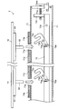
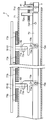
- the internal block diagram of the fixing device of the solar cell panel which concerns on 2nd Embodiment. Explanatory drawing of the fixing method by the fixing device of the solar cell panel which concerns on 2nd Embodiment.
- Explanatory drawing of the fixing method by the fixing device of the solar cell panel which concerns on 2nd Embodiment. Explanatory drawing of the fixing method by the fixing device of the solar cell panel which concerns on 2nd Embodiment.
- Explanatory drawing of the fixing method by the fixing device of the solar cell panel which concerns on 2nd Embodiment. Explanatory drawing of the fixing method by the fixing device of the solar cell panel which concerns on 2nd Embodiment.
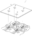
- FIG. 1 is a top view of the fixing device 1 of the solar cell panel which concerns on 1st Embodiment.
- FIG. 2 is a perspective view of the solar cell panel fixing device 1 according to the first embodiment.
- FIG. 3 is sectional drawing of the fixing device 1 of the solar cell panel which concerns on 1st Embodiment.
- the configuration of the solar cell panel fixing device 1 (hereinafter simply referred to as the fixing device 1) according to the first embodiment will be described below with reference to FIGS.
- the fixing device 1 is attached to a metal fitting 20 (engaged member) attached to the back surface of each solar cell panel 10, a frame 30 for supporting and fixing a plurality of solar cell panels 10, and one end of the frame 30 A handle 40 is used when a plurality of solar cell panels 10 are collectively fixed to the frame 30.
- the solar cell panel 10 is “borderless”, that is, a frameless solar cell panel without a frame surrounding the end of the solar cell panel is used.
- a rimmed solar panel may be used.
- the weight of the solar cell panel 10 is reduced, so that the weight of the frame 30 for supporting and fixing the solar cell panel 10 can be reduced and the manufacturing cost can be reduced.
- moisture such as rainwater does not accumulate in the frame, it is possible to prevent moisture from infiltrating into the solar cell panel 10. Therefore, the life of the solar cell panel 10 can be extended.
- the metal fitting 20 has a rectangular base plate (base plate) 21 attached to the back surface of the solar cell panel 10, a protrusion 22 protruding in a substantially vertical direction from the substrate 21, and a large diameter portion 23 provided at the tip of the protrusion 22. And (see FIG. 3).
- the metal fitting 20 is attached to the back surface of the solar cell panel 10 by applying an adhesive to the substrate 21.
- the diameter D2 of the large diameter portion 23 is larger than the diameter D1 of the protrusion 22.
- two types of such metal fittings 20 are shown.
- the metal fitting 20 on the left side of FIG. 3 is an example in which the large diameter portion 23 is spherical
- the metal fitting 20 on the right side of FIG. 3 is an example in which the large diameter portion 23 is cylindrical.
- the shape of the large diameter part 23 is not limited to spherical shape or cylindrical shape shown in FIG. 3, It can be set as various shapes.
- the number of metal fittings 20 attached to each solar cell panel 10 may not necessarily be four, for example, six or eight May be. However, the number of metal fittings 20 attached to each solar cell panel 10 is preferably four or more because the solar cell panel 10 can be stably fixed.
- the frame 30 is disposed in parallel with the fixed frame 31 (first frame) of a flat plate shape supporting the plurality of solar cell panels 10 and the longitudinal direction of the fixed frame 31, and is moved in parallel to the fixed frame 31.
- a flat plate-like moving frame 32 (second frame) which engages with the metal fitting 20 and fixes a plurality of solar cell panels 10 collectively and a support frame 33 supporting the fixed frame 31 and the moving frame 32 Be done.
- a circular through hole 31 a (first through hole) having an outer diameter larger than that of the large diameter portion 23 provided at a predetermined position, and a moving frame 32 for locking the fixed frame 31.
- a screw hole 31 c to be screwed with the screw X is formed.
- an elastic member 31b made of rectangular rubber is disposed.
- a mounting bracket 31d for mounting the handle 40 to the fixed frame 31 is provided.
- the fixed frame 31 includes a first support member 31e for supporting the self (fixed frame 31) on the support frame 33, and a second support member 31f for supporting the back surface of the moving frame 32 described later.
- a circular through hole 32a (second through hole) provided at a position corresponding to the through hole 31a provided in the fixed frame 31 and a large size of the metal fitting 20 communicated with the through hole 32a
- a rectangular through hole 32 b (third through hole) smaller in diameter than the diameter portion 23 and larger in diameter than the protruding portion 22 of the metal fitting 20 and a screw for locking the moving frame 32 to the fixed frame 31
- a through hole 32c (fourth through hole) is formed.
- a metal fitting 32d provided with a screw hole (not shown) screwed with the screw 41 of the handle 40 is provided at the end of the moving frame 32.
- a screw hole screwed with a screw X for locking the moving frame 32 to the fixed frame 31 may be formed in the moving frame 32, and a through hole through which the screw X passes may be formed in the fixed frame 31. Also, a through hole (fifth through hole) may be formed instead of the screw hole 31 c, and locking may be performed using a bolt and a nut instead of the screw X.
- the handle 40 comprises a handle portion 41 and a screw 42 connected to the handle portion 41.
- the movable frame 32 can be moved parallel to the longitudinal direction of the fixed frame 31 by rotating the handle portion 41.
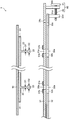
- FIGS. 4A to 6B are explanatory views of a fixing method of the solar cell panel by the fixing device 1.
- FIG. 4A, 5A and 6A are side views of the fixing device 1.
- FIG. FIGS. 4B, 5B, and 6B are plan views showing the positional relationship between the fixed frame 31 and the moving frame 32 in FIGS. 4A, 5A, and 6A, respectively.
- a fixing method of the solar cell panel 10 by the fixing device 1 will be described with reference to FIGS. 4A to 6B.
- the movable frame 32 is moved parallel to the longitudinal direction of the fixed frame 31, and the position where the through hole 32a of the movable frame 32 and the through hole 31a of the fixed frame 31 correspond, ie, movement
- the center of the through hole 32a of the frame 32 and the center of the through hole 31a of the fixed frame 31 are set in advance so as to be substantially coincident with each other.
- the fixing device 1 of the solar cell panel includes the large diameter portion 23 of the metal fitting 20 attached to the back surface of the solar cell panel 10, the through hole 31a of the fixed frame 31, and the moving frame After passing through the 32 through holes 32 a, the movable frame 32 is moved in parallel with the longitudinal direction of the fixed frame 31 to fix the solar cell panel 10.
- the plurality of solar cell panels 10 disposed on the frame 30 can be collectively fixed. Further, since the large diameter portion 23 of the metal fitting 20 is inserted through the through hole 31a provided at the predetermined position of the fixed frame 31, the arrangement and positioning of the solar cell panel 10 on the fixed frame 31 are simultaneously performed. be able to. As a result, the efficiency of the installation work of the solar cell panel 10 is significantly improved.
- the fixing of the plurality of solar cell panels 10 can be released collectively by operating the handle 40. For this reason, when replacing the defective solar cell panel 10, it is not necessary to remove the other defective solar cell panel 10, and the working efficiency is improved.
- the handle 40 can not be operated and therefore theft can be easily prevented.
- the elastic member 31b is disposed on the fixed frame 31 on which the solar cell panel 10 is disposed, generation of a gap between the metal fitting 20 attached to the back surface of the solar cell panel 10 and the frame 30 is suppressed can do. For this reason, it can suppress that the solar cell panel 10 shakes with a wind, an earthquake, etc., and a crack and a chipping arise in glass which comprises the solar cell panel 10.
- the structure of the fixing device 1 is simple, the manufacturing cost can be suppressed.
- FIG. 7A and 7B are side views of a fixing device 1A of a solar cell panel according to a modification of the first embodiment.
- FIG. 7A is a view showing a state before fixing the solar cell panel.
- FIG. 7B is a view showing a state after the solar cell panel is fixed.
- the fixing device 1A is different from the fixing device 1 described with reference to FIGS. 1 to 6B in that the fixing device 1A includes a handle 50.
- the other configuration is the same as that of the fixing device 1 and, therefore, the same reference numeral is given to the same configuration and the redundant description will be omitted.
- the handle 50 has a bar-shaped handle 51 whose one end is rotatably connected to the fixed frame 31 about the rotation shaft 51a and a rod-shaped link 52 whose one end is rotatably connected about the rotation shaft 52a. And consists of An elongated hole 51 b is formed substantially in the center of the handle portion 51 in the longitudinal direction of the handle portion 51. Further, on the other end side of the link portion 52, a connecting member 52b which is slidably connected along the long hole 51b of the handle portion 51 is provided.
- the movable frame 32 By moving the grip portion 51c of the handle portion 51 in the direction of the arrow ⁇ , the movable frame 32 extends in the longitudinal direction of the fixed frame 31 to a position where the through hole 32c of the movable frame 32 is directly below the screw hole 31c of the fixed frame 31 It moves parallel to (right direction of FIG. 7A) (refer FIG. 7A).
- the screw X is inserted from the through hole 32 c of the movable frame 32 and screwed into the screw hole 31 c of the fixed frame 31.
- the antitheft lock Y is attached to the handle 50 so that the handle 50 can not be operated (see FIG. 7B).
- it is the same as the effect of the fixing device 1 which concerns on 1st Embodiment.
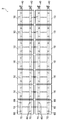
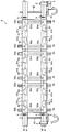
- FIG. 8 is a plan view of a fixing device of a solar cell panel according to a second embodiment.
- FIG. 9 is a perspective view of the solar cell panel fixing device 2 according to the second embodiment.
- FIG. 10A and FIG. 10B are internal block diagrams of the fixing device 2 of the solar cell panel concerning 2nd Embodiment.
- the configuration of the solar cell panel fixing device 2 (hereinafter simply referred to as the fixing device 2) according to the second embodiment will be described below with reference to FIGS. 8 to 10B.
- the same components as those of the fixing device 1 described with reference to FIGS. 1 to 6B will be assigned the same reference numerals and overlapping descriptions will be omitted.
- FIG. 10A and 10B in order to show the movement flame
- the fixing device 2 is attached to a bracket 70 (engaged member) attached to the back surface of each solar cell panel 10, a frame 70 for supporting and fixing a plurality of solar cell panels 10, and one end of the frame 70
- a handle 40 is used to fix a plurality of solar cell panels 10 at one time to the frame 70.
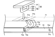
- the metal fitting 60 includes a rectangular base plate (base plate) 61 attached to the back surface of each solar cell panel 10, a pair of projecting portions 62a and 62b projecting in a substantially vertical direction from the substrate 61, and tips of the pair of projecting portions 62a and 62b And an engaged portion 62 consisting of a connecting portion 62c connecting the two.
- the metal fitting 60 is attached to the back surface of the solar cell panel 10 by applying an adhesive to the substrate 61.
- four brackets 60 are attached to each solar cell panel 10.
- the number of brackets 60 attached to each solar cell panel 10 may not necessarily be four, and may be six or eight, for example. .
- four or more metal fittings 60 attached to each solar cell panel 10 are preferable because they can stably fix the solar cell panel 10.
- the frame 70 is a box-shaped fixed frame 71 (first frame) for supporting a plurality of solar cell panels 10, and a flat plate shape housed in the fixed frame 71 and moving in parallel with the longitudinal direction of the fixed frame 71.
- the movable frame 72 (second frame) is disposed in the fixed frame 71, and is rotated according to the parallel movement of the movable frame 32 to engage with the engaged portion 62 of the metal fitting 60, and a plurality of solar cell panels 10 is comprised from the rotation member 73 which fixes collectively, and the support frame 74 which supports the fixed frame 71. As shown in FIG.
- the moving frame 72 is formed with a notch 72a for inserting the protruding portion 73a of the rotating member 73, and a screw hole 72d screwed with a screw X for locking the moving frame 72 to the fixed frame 71. ing. Further, at the end of the moving frame 72, a metal fitting 72c provided with a screw hole (not shown) screwed with the screw 41 of the handle 40 is provided (see FIGS. 11A and 11B described later).
- a screw hole screwed with the screw X for locking the moving frame 72 to the fixed frame 71 may be formed in the fixed frame 71, and a through hole through which the screw X passes may be formed in the moving frame 72. Also, a through hole may be formed instead of the screw hole 31c, and locking may be performed using a bolt and a nut instead of the screw X.
- the rotating member 73 is engaged with the fixed frame 71 so as to be rotatable around the rotation shaft 73 b, and the protrusion 73 a is moved by moving the moving frame 72 in parallel with the longitudinal direction of the fixed frame 71. While sliding in the notch portion 72a, it rotates about the rotation shaft 73b. Thereby, the engaging portion 73 c engages with the engaged portion 62 of the metal fitting 60.
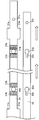
- FIGS. 11A, 12A, and 13A are explanatory views of a fixing method of the solar cell panel by the fixing device 2.
- FIG. 11A, 12A and 13A are side views of the fixing device 2.
- FIG. 11A, FIG. 12A, and FIG. 13A in order to show the movement flame
- 11B, 12B, and 13B are cross-sectional views of the fixed frame 71 and the moving frame 72 taken along line XX in FIGS. 11A, 12A, and 13A, respectively.
- FIGS. 11A to 13B a fixing method of the solar cell panel 10 by the fixing device 2 will be described with reference to FIGS. 11A to 13B.
- the same components as those of the fixing device 1 described with reference to FIGS. 1 to 6B will be assigned the same reference numerals and overlapping descriptions will be omitted.
- the handle 40 is operated to move the moving frame 72 parallel to the longitudinal direction of the fixed frame 71, and the rotating member 73 is inclined rearward (right side in the drawing). As a result, when the metal fitting 60 is inserted from the opening of the fixed frame 71, the rotary member 73 is retracted in advance to a position not in contact with the engaged portion 62 of the metal fitting 60.
- the rotating member 73 By moving the moving frame 72 parallel to the longitudinal direction of the fixed frame 71, the rotating member 73 can be rotated along the rotating shaft 73b while the projecting portion 73a of the rotating member 73 slides in the notch 72a of the moving frame 72. It rotates around the center.
- the engaging portion 73 c engages with the engaged portion 62 of the metal fitting 60, and the plurality of solar cell panels 10 disposed on the frame 70 are collectively fixed to the frame 70.
- the fixing device 2 for the solar cell panel inserts the engaged portion 62 of the metal fitting 60 attached to the back surface of the solar cell panel 10 into the opening 71 a of the fixing frame 71
- the moving member 72 is rotated by moving the moving frame 72 in parallel with the longitudinal direction of the fixed frame 71, and the engaging portion 73 c of the rotating member 73 is engaged with the engaged portion 62 of the metal fitting 60. It is composed of
- the plurality of solar cell panels 10 disposed on the frame 70 can be collectively fixed.
- the other effects are the same as those of the fixing device 1 for the solar cell panel according to the first embodiment.
- the handle 50 may be provided instead of the handle 40.
- FIG. 14 is a plan view of the fixing device 3 of the solar cell panel according to the third embodiment.
- FIG. 15 is a perspective view of a fixing device of a solar cell panel according to a third embodiment.
- FIG. 16 is a side view of the fixing device of the solar cell panel according to the third embodiment.
- the configuration of the solar cell panel fixing device 3 (hereinafter, simply referred to as the fixing device 3) according to the third embodiment will be described below with reference to FIGS.
- the same components as those of the fixing device 1 described with reference to FIGS. 1 to 6B will be assigned the same reference numerals and overlapping descriptions will be omitted.
- the fixing device 3 is attached to both ends of the frame 90, a bracket 80 (engaged member) attached to the back surface of each solar cell panel 10, a frame 90 for supporting and fixing the plurality of solar cell panels 10, And a handle 40 used when fixing a plurality of solar cell panels 10 together to the frame 90.
- the metal fitting 80 includes a rectangular base plate (base plate) 81 attached to the back surface of each solar cell panel 10, and an engaged portion 82 which protrudes substantially perpendicularly from the base plate 81 and whose front end is bent.
- the metal fitting 80 is attached to the back surface of the solar cell panel 10 by applying an adhesive to the substrate 81.
- four brackets 80 are attached to each solar cell panel 10, but the number of brackets 80 attached to each solar cell panel 10 is not necessarily limited to four, and may be six or eight, for example. .
- the number of metal fittings 80 attached to each solar cell panel 10 is preferably four or more because the solar cell panel 10 can be stably fixed.
- the frame 90 is disposed parallel to the fixed direction of the fixed frame 91 and the fixed frame 91 (first frame) of a quadrangular prism shape supporting the plurality of solar cell panels 10, and relative to the fixed frame 91
- a concave portion 91a that engages with the engaged portion 82 of the metal fitting 80 is formed at a predetermined position.
- an elastic member 91b made of rubber is disposed around the recess 91a.
- the fixed frame 91 is formed with a screw hole 91 c screwed with a screw for locking the moving frame 92 to the fixed frame 91.
- a projecting portion 92a which protrudes toward the inside of the groove 93a of the supporting frame 93 and moves the moving frame 92 in parallel along the groove 93a of the supporting frame 93, and the moving frame 92 to the fixed frame 91 A through hole 92b (fourth through hole) for passing a screw for locking is formed.
- a screw hole screwed with a screw for locking the moving frame 92 to the fixed frame 91 may be formed in the moving frame 92, and a through hole through which the screw passes may be formed in the fixed frame 91. Also, a through hole may be formed instead of the screw hole 31c, and locking may be performed using a bolt and a nut instead of the screw X.
- handles 40 are provided at both ends of the fixed frame 91.
- the handle 40 includes a handle portion 41 and a screw 42 connected to the handle portion 41.
- the movable frame 92 is moved in a direction perpendicular to the longitudinal direction of the fixed frame 91 by rotating the handle portion 41. It can be done.
- FIGS. 17A to 19B are explanatory diagrams of a fixing method by the fixing device 3.
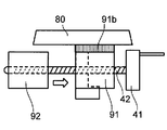
- 17A, 18A and 19A show cross-sectional views of the fixing device 3.
- FIG. 17B, 18B, and 19B are partially enlarged views of FIGS. 17A, 18A, and 19A.
- the screw holes 91c of the fixed frame 91 and the through holes 92b of the moving frame 92 are not shown.
- a method of fixing the solar cell panel 10 by the fixing device 3 will be described with reference to FIGS. 17A to 19B.
- the movable frame 92 is fixed by operating the handles 40 provided at both ends of the frame 90 so that the engaged portion 82 of the metal fitting 80 is held between the movable frame 92 and the recess 91 a of the fixed frame 91. It moves in the direction perpendicular to the longitudinal direction of 91 (rightward in FIGS. 19A and 19B). Thereby, the plurality of solar cell panels 10 disposed on the frame 90 are collectively fixed to the frame 90.
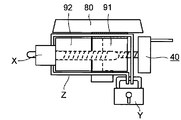
- the screw X is inserted from the through hole 92 c of the moving frame 92 and screwed into the screw hole 91 c of the fixed frame 91. Further, the fixed frame 91 and the moving frame 92 are fastened by the fastener Z, and the antitheft lock Y is attached to the fastener Z. As in the case of the fixing devices 1 and 2 according to the first and second embodiments, the antitheft lock Y may be attached to the handle 40 so that the handle 40 can not be operated.
- the fixing device 3 for the solar cell panel hooks the engaged portion 82 of the metal fitting 80 attached to the back surface of the solar cell panel 10 to the recess 91 a of the fixing frame 91
- the movable frame 92 is moved in the direction perpendicular to the longitudinal direction of the fixed frame 91 to fix the solar cell panel 10.
- the plurality of solar cell panels 10 disposed on the frame 90 can be collectively fixed.
- the other effects are the same as those of the fixing device 1 for the solar cell panel according to the first embodiment.
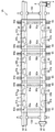
- FIG. 20 is a plan view of a fixing device 3A for a solar cell panel (hereinafter, simply referred to as a fixing device 3A) according to a modification of the third embodiment.
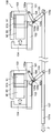
- 21A and 21B are enlarged side views of a handle 100 according to a modification of the third embodiment.
- the fixing device 3A is different from the fixing device 3 described with reference to FIGS. 15 to 19B in that the fixing device 3A includes the handle 100.
- the other configuration is the same as that of the fixing device 3, and therefore, the same configuration is denoted by the same reference numeral, and redundant description will be omitted.
- the handle 100 is provided on a box-shaped housing 101, a movable body 102, and a housing 101, and a first pinching portion 103 whose tip is bent is provided on the movable body 102, and the tip is bent.
- the rod-shaped first link portion 105 connected to the moving body 102, the rod-shaped second link portion 106 connected to the housing 101, and the first link portion
- a handle portion 107 is connected to the 105 and the second link portion 106.
- the movable body 102 is accommodated in the housing 101, and is configured to be movable in the housing 101 along the longitudinal direction of the housing 101.
- the second holding unit 104 moves in the longitudinal direction of the housing 101 (the left and right direction in FIG. 21A) as the movable body 102 moves.
- the first holding unit 103 and the second holding unit 104 hold and fix the fixed frame 91 and the moving frame 92.
- One end side of the first link portion 105 is rotatably connected to the movable body 102 about the rotation shaft 105a, and the other end side is rotatably connected to the handle portion 107 about the rotation shaft 105b.
- a long hole 105 c is formed substantially in the center of the first link portion 105 along the longitudinal direction of the first link portion 105.
- One end side of the second link portion 106 is coupled to the casing 101 so as to be rotatable about the central axis 106 a.
- a clasp 106b which can slide along the long hole 105cb of the first link portion 105 is provided on the other end side of the second link portion 106.
- the handle portion 107 is connected to the other end of the first connection portion 105.
- the movable body 102 moves in the housing 101 in the right direction of FIG. 21A.
- the second holding portion 104 provided on the moving body 102 moves in the right direction of FIG. 21A, and as shown in FIG. 21B, the first holding portion 103 of the handle 100 and the The fixed frame 91 and the moving frame 92 are held by the two holding portions 104.
- the antitheft lock Y may be attached to the handle 100 so that the handle 100 can not be operated.
- the effects are the same as the effects of the fixing device 1 according to the third embodiment.
- the present invention can be used as a fixing device of a solar cell panel. Therefore, it has industrial applicability.
- SYMBOLS 1 Fixing device of solar cell panel, 10 ... Solar cell panel, 20 ... Bracket (member to be engaged), 21 ... Substrate (base plate), 22 ... Projection part, 23 ... Large diameter part, 30 ... Frame, 31 ...
- Fixation Frame (first frame) 31a through hole (first through hole) 31b elastic member 31c screw hole 31d bracket 32 moving frame (second frame) 32a through hole Second through hole) 32b through hole (third through hole) 32c through hole (fourth through hole) 32d bracket 31e first support member 31f second support member , 33: support frame, 40: handle, 41: handle portion, 42: screw, 50: handle, 51: handle portion, 52: link portion, 51a: rotation shaft, 51b: elongated hole, 51c: grip portion, 52a: Rotating shaft, 52b ...
- 1st clamping 104 second holding part, 105: first link part, 105a: rotating shaft, 105b: clasp, 106: second link part, 106a: rotating shaft, 106b: elongated hole, 106c: rotating shaft, 107 ... handle portion, X ... screw, Y ... lock, Z ... fastener.
Landscapes
- Engineering & Computer Science (AREA)
- Physics & Mathematics (AREA)
- Life Sciences & Earth Sciences (AREA)
- Sustainable Development (AREA)
- Sustainable Energy (AREA)
- Thermal Sciences (AREA)
- Chemical & Material Sciences (AREA)
- Combustion & Propulsion (AREA)
- Mechanical Engineering (AREA)
- General Engineering & Computer Science (AREA)
- Photovoltaic Devices (AREA)
- Roof Covering Using Slabs Or Stiff Sheets (AREA)
Abstract
複数枚の太陽電池パネルの裏面に夫々取り付けられた複数の被係合部材と、複数枚の太陽電池パネルを支持する第1のフレームと、第1のフレームに対して相対的に移動し、前記複数枚の太陽電池パネルの裏面に夫々取り付けられた複数の被係合部材を一括して固定するための第2のフレームと、を備える。
Description
本発明は、太陽電池パネルの固定装置に関し、特に、複数枚の太陽電池パネルを一括して固定できる太陽電池パネルの固定装置に関する。
近年、再生可能エネルギーとして太陽光発電が注目されている。太陽光発電では、太陽光を電気に変換する太陽電池パネルを設置するが、太陽電池パネル1枚の発電量は小さい。このため、必要な電力を確保するために、多数の太陽電池パネルの設置が必要となる。特に、大規模発電を行う場合、数百枚から数千枚もの太陽電池パネルを設置する必要がある。
通常、太陽電池パネルは、地面もしくは屋根等に配置された架台上に設置される。例えば、大規模発電の場合は、太陽電池パネルを支持する金具が設けられたコンクリートブロックを多数地面に配置し、この金具に太陽電池パネルを取り付けるようにしたものが提案されている(特許文献1参照)。また、屋根に設置する場合は、野地板に敷設された板金上に太陽電池パネルの端部を挟持するレールを設け、このレール間に複数枚の太陽電池パネルをスライドさせて設置するようにしたものが提案されている(特許文献2参照)。
しかしながら、特許文献1に開示されたものは、数百枚から数千枚もの太陽電池パネルを手作業で一枚ずつボルトとナットを用いて金具に固定する必要があり作業効率が非常に悪い。また、各太陽電池パネルは、ボルトとナットを用いて固定されているだけであり太陽電池パネルの盗難を防止することができない。
特許文献2に開示されたものは、同一のレールに複数枚の太陽電池パネルをスライドさせて設置することができる。しかしながら、不具合の生じた太陽電池パネルを交換する際には、同一のレールに設置された他の太陽電池パネルを該レールから抜き取る必要があり作業効率が悪い。また、レール端部には、水切り板がねじ止めされているだけであり、この水切り板を取り外すことで太陽電池パネルをレールから抜き取ることができるため太陽電池パネルの盗難を防止することが難しい。
本発明は、上記の事情に対処してなされたもので、複数枚の太陽電池パネルを一括して固定できる太陽電池パネルの固定装置を提供することを目的とする。
本発明の太陽電池パネルの固定装置は、複数枚の太陽電池パネルの裏面に夫々取り付けられた複数の被係合部材と、複数枚の太陽電池パネルを支持する第1のフレームと、第1のフレームに対して相対的に移動し、複数枚の太陽電池パネルの裏面に夫々取り付けられた複数の被係合部材を一括して固定するための第2のフレームと、を備える。
本発明によれば、複数枚の太陽電池パネルを一括して固定できる太陽電池パネルの固定装置を提供できる。
(第1の実施形態)
図1は、第1の実施形態に係る太陽電池パネルの固定装置1の平面図である。図2は、第1の実施形態に係る太陽電池パネルの固定装置1の斜視図である。図3は、第1の実施形態に係る太陽電池パネルの固定装置1の断面図である。以下、図1~図3を参照して、第1の実施形態に係る太陽電池パネルの固定装置1(以下、単に固定装置1と称する)の構成について説明する。
図1は、第1の実施形態に係る太陽電池パネルの固定装置1の平面図である。図2は、第1の実施形態に係る太陽電池パネルの固定装置1の斜視図である。図3は、第1の実施形態に係る太陽電池パネルの固定装置1の断面図である。以下、図1~図3を参照して、第1の実施形態に係る太陽電池パネルの固定装置1(以下、単に固定装置1と称する)の構成について説明する。
(固定装置1の構成)
固定装置1は、それぞれの太陽電池パネル10の裏面に取り付けられる金具20(被係合部材)と、複数枚の太陽電池パネル10を支持及び固定するフレーム30と、フレーム30の一端に取り付けられ、複数枚の太陽電池パネル10を一括してフレーム30に固定する際に用いるハンドル40とを備える。
固定装置1は、それぞれの太陽電池パネル10の裏面に取り付けられる金具20(被係合部材)と、複数枚の太陽電池パネル10を支持及び固定するフレーム30と、フレーム30の一端に取り付けられ、複数枚の太陽電池パネル10を一括してフレーム30に固定する際に用いるハンドル40とを備える。
なお、この第1の実施形態では、太陽電池パネル10として「縁無し」、つまり、太陽電池パネルの端部を囲うフレームが無いフレームレスの太陽電池パネルを使用することを想定しているが、縁のある太陽電池パネルを使用してもよい。
太陽電池パネル10をフレームレスとした場合、太陽電池パネル10が軽量化されるため、太陽電池パネル10を支持及び固定するフレーム30を軽量化して製造コストを低減することができる。また、雨水等の水分がフレームに溜まらないため太陽電池パネル10内に水分が浸み込むのを防止できる。このため太陽電池パネル10の寿命を長期化することができる。
金具20は、太陽電池パネル10の裏面に取り付けられる矩形の基板(ベースプレート)21と、この基板21から略垂直方向に突出した突出部22と、突出部22の先端に設けられた大径部23とから構成される(図3参照)。金具20は、基板21に接着剤を塗布することにより、太陽電池パネル10の裏面に取り付けられる。大径部23の直径D2は、突出部22の直径D1よりも大きい。この実施形態では、このような金具20として2種類のものを示した。図3の左側の金具20は、大径部23を球形とした例であり、図3の右側の金具20は、大径部23を円柱形とした例である。なお、大径部23の形状は、図3に示した球形又は円柱形に限定されず、種々の形状とすることができる。
また、この実施形態では、各太陽電池パネル10に4個ずつ金具20を取り付けているが、各太陽電池パネル10に取り付ける金具20は、必ずしも4個でなくともよく、例えば、6個や8個でもよい。ただし、各太陽電池パネル10に取り付ける金具20は、4個以上であることが太陽電池パネル10を安定して固定することができ好ましい。
フレーム30は、複数枚の太陽電池パネル10を支持する平板形状の固定フレーム31(第1のフレーム)と、固定フレーム31の長手方向と平行に配置され、固定フレーム31に平行に移動することにより金具20と係合して、複数枚の太陽電池パネル10を一括して固定する平板形状の移動フレーム32(第2のフレーム)と、固定フレーム31及び移動フレーム32を支持する支持フレーム33から構成される。
固定フレーム31には、所定の位置に設けられた大径部23よりも外径が大きな円形の貫通孔31a(第1の貫通孔)と、移動フレーム32を固定フレーム31に係止するためのねじXと螺合するねじ孔31cとが形成されている。貫通孔31aの周囲には、矩形上のゴムからなる弾性部材31bが配設されている。固定フレーム31の端部には、ハンドル40を固定フレーム31に取り付けるための取り付け金具31dが設けられている。また、固定フレーム31は、自己(固定フレーム31)を支持フレーム33上に支持するための第1の支持部材31eと、後述する移動フレーム32の裏面を支持するための第2の支持部材31fを備える。
移動フレーム32には、固定フレーム31に設けられている貫通孔31aと対応する位置に設けられた円形の貫通孔32a(第2の貫通孔)と、この貫通孔32aに連通し金具20の大径部23よりも小径で、かつ金具20の突出部22よりも大径の矩形の貫通孔32b(第3の貫通孔)と、移動フレーム32を固定フレーム31に係止するためのねじを通す貫通孔32c(第4の貫通孔)とが形成されている。また、移動フレーム32の端部には、ハンドル40のねじ41と螺合するねじ穴(図示せず)が設けられた金具32dが設けられている。
なお、移動フレーム32を固定フレーム31に係止するためのねじXと螺合するねじ孔を移動フレーム32に形成し、ねじXを通す貫通孔を固定フレーム31に形成してもよい。また、ねじ孔31cの代わりに貫通孔(第5の貫通孔)を形成し、ねじXの代わりにボルトとナットとを用いて係止してもよい。
ハンドル40は、ハンドル部41と、このハンドル部41に連結されたねじ42とから構成される。ハンドル部41を回転させることにより、移動フレーム32を固定フレーム31の長手方向に対して平行に移動させることができる。
(固定装置1の操作)
図4A~図6Bは、固定装置1による太陽電池パネルの固定方法の説明図である。図4A、図5A、図6Aは、固定装置1の側面図である。図4B、図5B、図6Bは、それぞれ図4A、図5A、図6Aにおける、固定フレーム31及び移動フレーム32の位置関係を示す平面図である。以下、図4A~図6Bを参照して、固定装置1による太陽電池パネル10の固定方法について説明する。
図4A~図6Bは、固定装置1による太陽電池パネルの固定方法の説明図である。図4A、図5A、図6Aは、固定装置1の側面図である。図4B、図5B、図6Bは、それぞれ図4A、図5A、図6Aにおける、固定フレーム31及び移動フレーム32の位置関係を示す平面図である。以下、図4A~図6Bを参照して、固定装置1による太陽電池パネル10の固定方法について説明する。
(初期操作)
ハンドル40を操作することにより、移動フレーム32を固定フレーム31の長手方向に対して平行に移動させ、移動フレーム32の貫通孔32aと固定フレーム31の貫通孔31aとが対応する位置、すなわち、移動フレーム32の貫通孔32aの中心と固定フレーム31の貫通孔31aの中心とが略一致する位置となるように予めセットしておく。
ハンドル40を操作することにより、移動フレーム32を固定フレーム31の長手方向に対して平行に移動させ、移動フレーム32の貫通孔32aと固定フレーム31の貫通孔31aとが対応する位置、すなわち、移動フレーム32の貫通孔32aの中心と固定フレーム31の貫通孔31aの中心とが略一致する位置となるように予めセットしておく。
(第1操作:図4A,図4B参照)
太陽電池パネル10の裏面に取り付けられた金具20の大径部23を固定フレーム31の貫通孔31a及び移動フレーム32の貫通孔32aに通過させ、太陽電池パネル10を固定フレーム31の弾性部材31b上に載置する。
太陽電池パネル10の裏面に取り付けられた金具20の大径部23を固定フレーム31の貫通孔31a及び移動フレーム32の貫通孔32aに通過させ、太陽電池パネル10を固定フレーム31の弾性部材31b上に載置する。
(第2操作:図5A,図5B参照)
ハンドル40を操作し、金具20の大径部23と移動フレーム32の貫通孔32bとが係合するまで移動フレーム32を固定フレーム31の長手方向(図5A及び図5Bの右方向)に対して平行に移動させる。これにより、フレーム30上に配置された複数の太陽電池パネル10が一括してフレーム30に固定される。
ハンドル40を操作し、金具20の大径部23と移動フレーム32の貫通孔32bとが係合するまで移動フレーム32を固定フレーム31の長手方向(図5A及び図5Bの右方向)に対して平行に移動させる。これにより、フレーム30上に配置された複数の太陽電池パネル10が一括してフレーム30に固定される。
(第3操作:図6A,図6B参照)
ねじXを移動フレーム32の貫通孔32cから挿入して固定フレーム31のねじ孔31cへ螺合させる。また、盗難防止用の錠前Yをハンドル40に取り付けてハンドル40を操作できないようにする。
ねじXを移動フレーム32の貫通孔32cから挿入して固定フレーム31のねじ孔31cへ螺合させる。また、盗難防止用の錠前Yをハンドル40に取り付けてハンドル40を操作できないようにする。
以上のように、第1の実施形態に係る太陽電池パネルの固定装置1は、太陽電池パネル10の裏面に取り付けられた金具20の大径部23を、固定フレーム31の貫通孔31a及び移動フレーム32の貫通孔32aに通過させた後、移動フレーム32を固定フレーム31の長手方向と平行に移動させて太陽電池パネル10を固定するように構成している。
このため、フレーム30上に配置された複数枚の太陽電池パネル10を一括して固定することができる。また、固定フレーム31の所定の位置に設けられた貫通孔31aに金具20の大径部23を通すように構成しているので、太陽電池パネル10の固定フレーム31への配置と位置決めを同時に行うことができる。その結果、太陽電池パネル10の設置作業の効率が大幅に向上する。
また、太陽電池パネル10の固定を解除する際にも、ハンドル40を操作することにより、複数枚の太陽電池パネル10の固定を一括して解除することができる。このため、不具合の生じた太陽電池パネル10を交換する際に、不具合の生じていない他の太陽電池パネル10まで取り外す必要がなく作業効率が向上する。
さらに、ハンドル40を錠前Yにより施錠することで、ハンドル40を操作することができなくなるため簡単に盗難を防止することができる。また、太陽電池パネル10を配置する固定フレーム31上に弾性部材31bを配設しているので、太陽電池パネル10の裏面に取り付けられた金具20とフレーム30との間に隙間が生じるのを抑制することができる。このため、太陽電池パネル10が風や地震等により揺れて太陽電池パネル10を構成するガラスにひびや欠けが生じることを抑制することができる。また、固定装置1の構成が簡易であるため製造コストを抑制することができる。
(第1の実施形態の変形例)
図7A及び図7Bは、第1の実施形態の変形例に係る太陽電池パネルの固定装置1Aの側面図である。図7Aは、太陽電池パネルを固定する前の状態を示す図である。図7Bは、太陽電池パネルを固定した後の状態を示す図である。以下、図7A及び図7Bを参照して、第1の実施形態の変形例に係る太陽電池パネルの固定装置1A(以下、単に固定装置1Aと称する)の構成について説明する。なお、固定装置1Aは、ハンドル50を備えている点が、図1~図6Bを参照して説明した固定装置1と異なる。その他の構成は固定装置1と同じであるため、同一の構成には同一の符号を付して重複した説明を省略する。
図7A及び図7Bは、第1の実施形態の変形例に係る太陽電池パネルの固定装置1Aの側面図である。図7Aは、太陽電池パネルを固定する前の状態を示す図である。図7Bは、太陽電池パネルを固定した後の状態を示す図である。以下、図7A及び図7Bを参照して、第1の実施形態の変形例に係る太陽電池パネルの固定装置1A(以下、単に固定装置1Aと称する)の構成について説明する。なお、固定装置1Aは、ハンドル50を備えている点が、図1~図6Bを参照して説明した固定装置1と異なる。その他の構成は固定装置1と同じであるため、同一の構成には同一の符号を付して重複した説明を省略する。
ハンドル50は、一端側が回転軸51aを中心として回転可能に固定フレーム31に連結された棒形状のハンドル部51と、一端側が回転軸52aを中心として回転可能に連結された棒形状のリンク部52とから構成される。ハンドル部51の略中央には、ハンドル部51の長手方向に長孔51bが形成されている。また、リンク部52の他端側には、ハンドル部51の長孔51bに沿ってスライド可能に連結する連結部材52bが設けられている。ハンドル部51の把持部51cを矢印αの向きに引くことにより、移動フレーム32の貫通孔32cが固定フレーム31のねじ孔31cの真下となる位置まで、移動フレーム32が固定フレーム31の長手方向(図7Aの右方向)に対して平行に移動する(図7A参照)。
その後、第1の実施形態と同様に、ねじXを移動フレーム32の貫通孔32cから挿入して固定フレーム31のねじ孔31cへ螺合させる。その後、盗難防止用の錠前Yをハンドル50に取り付けてハンドル50を操作できないようにする(図7B参照)。なお、効果については、第1の実施形態に係る固定装置1の効果と同じである。
(第2の実施形態)
図8は、第2の実施形態に係る太陽電池パネルの固定装置の平面図である。図9は、第2の実施形態に係る太陽電池パネルの固定装置2の斜視図である。図10A及び図10Bは、第2の実施形態に係る太陽電池パネルの固定装置2の内部構成図である。以下、図8~図10Bを参照して、第2の実施形態に係る太陽電池パネルの固定装置2(以下、単に固定装置2と称する)の構成について説明する。なお、図1~図6Bを参照して説明した固定装置1と同一の構成には同一の符号を付して重複した説明を省略する。また、図10A及び図10Bでは、固定フレーム71内の移動フレーム72及び回転部材73を示すため固定フレーム71を破線で示した。
図8は、第2の実施形態に係る太陽電池パネルの固定装置の平面図である。図9は、第2の実施形態に係る太陽電池パネルの固定装置2の斜視図である。図10A及び図10Bは、第2の実施形態に係る太陽電池パネルの固定装置2の内部構成図である。以下、図8~図10Bを参照して、第2の実施形態に係る太陽電池パネルの固定装置2(以下、単に固定装置2と称する)の構成について説明する。なお、図1~図6Bを参照して説明した固定装置1と同一の構成には同一の符号を付して重複した説明を省略する。また、図10A及び図10Bでは、固定フレーム71内の移動フレーム72及び回転部材73を示すため固定フレーム71を破線で示した。
(固定装置2の構成)
固定装置2は、それぞれの太陽電池パネル10の裏面に取り付けられる金具60(被係合部材)と、複数枚の太陽電池パネル10を支持及び固定するフレーム70と、フレーム70の一端に取り付けられ、複数枚の太陽電池パネル10を一括してフレーム70に固定する際に用いるハンドル40とを備える。
固定装置2は、それぞれの太陽電池パネル10の裏面に取り付けられる金具60(被係合部材)と、複数枚の太陽電池パネル10を支持及び固定するフレーム70と、フレーム70の一端に取り付けられ、複数枚の太陽電池パネル10を一括してフレーム70に固定する際に用いるハンドル40とを備える。
金具60は、各太陽電池パネル10の裏面に取り付けられる矩形の基板(ベースプレート)61と、基板61から略垂直方向に突出した一対の突出部62a,62b及びこの一対の突出部62a,62bの先端を接続する接続部62cからなる被係合部62とから構成される。金具60は、基板61に接着剤を塗布することにより、太陽電池パネル10の裏面に取り付けられる。この実施形態では、各太陽電池パネル10に4個ずつ金具60を取り付けているが、各太陽電池パネル10に取り付ける金具60は、必ずしも4個でなくともよく、例えば、6個や8個でもよい。ただし、各太陽電池パネル10に取り付ける金具60は、4個以上であることが太陽電池パネル10を安定して固定することができ好ましい。
フレーム70は、複数枚の太陽電池パネル10を支持する箱型の固定フレーム71(第1のフレーム)と、固定フレーム71内に収容され、固定フレーム71の長手方向と平行に移動する平板形状の移動フレーム72(第2のフレーム)と、固定フレーム71内に配置され、移動フレーム32の平行移動に伴い回転動作して金具60の被係合部62と係合し、複数枚の太陽電池パネル10を一括して固定する回転部材73と、固定フレーム71を支持する支持フレーム74とから構成される。
固定フレーム71には、所定の位置に設けられた金具60の被係合部62を挿入するための開口71aと、移動フレーム72を固定フレーム71に係止するためのねじを通す貫通孔71c(第4の貫通孔)とが形成されている。また、開口71aの周囲には、矩形上のゴムからなる弾性部材71bが配設されている。さらに、固定フレーム71の端部には、ハンドル40を固定フレーム71に取り付けるための取り付け金具71dが設けられている(後述する図11A,図11Bを参照)。
移動フレーム72には、回転部材73の突出部73aを挿入するための切欠き部72aと、移動フレーム72を固定フレーム71に係止するためのねじXと螺合するねじ孔72dとが形成されている。また、移動フレーム72の端部には、ハンドル40のねじ41と螺合するねじ穴(図示せず)が設けられた金具72cが設けられている(後述する図11A,図11B参照)。
なお、移動フレーム72を固定フレーム71に係止するためのねじXと螺合するねじ孔を固定フレーム71に形成し、ねじXを通す貫通孔を移動フレーム72に形成してもよい。また、ねじ孔31cの代わりに貫通孔を形成し、ねじXの代わりにボルトとナットとを用いて係止してもよい。
回転部材73は、回転軸73bを中心として回転可能に固定フレーム71に係合されており、移動フレーム72を固定フレーム71の長手方向と平行に移動させることで、突出部73aが移動フレーム72の切欠き部72a内をスライドしながら回転軸73bを中心として回転動作する。これにより、係合部73cが金具60の被係合部62と係合する。
(固定装置2の動作)
図11A~図13Bは、固定装置2による太陽電池パネルの固定方法の説明図である。図11A、図12A、図13Aは、固定装置2の側面図である。図11A、図12A、図13Aでは、固定フレーム71内の移動フレーム72及び回転部材73を示すため固定フレーム71を断面図としている。図11B、図12B、図13Bは、それぞれ図11A、図12A、図13Aの線分X-Xにおける固定フレーム71及び移動フレーム72の断面図である。
図11A~図13Bは、固定装置2による太陽電池パネルの固定方法の説明図である。図11A、図12A、図13Aは、固定装置2の側面図である。図11A、図12A、図13Aでは、固定フレーム71内の移動フレーム72及び回転部材73を示すため固定フレーム71を断面図としている。図11B、図12B、図13Bは、それぞれ図11A、図12A、図13Aの線分X-Xにおける固定フレーム71及び移動フレーム72の断面図である。
以下、図11A~図13Bを参照して、固定装置2による太陽電池パネル10の固定方法について説明する。なお、図1~図6Bを参照して説明した固定装置1と同一の構成には同一の符号を付して重複した説明を省略する。
(初期操作)
ハンドル40を操作して、移動フレーム72を固定フレーム71の長手方向に対して平行に移動させ、回転部材73が後方(図面右側)に傾いた状態とする。これにより、金具60を固定フレーム71の開口から挿入した際に金具60の被係合部62と接触しない位置まで回転部材73を予め退避させておく。
ハンドル40を操作して、移動フレーム72を固定フレーム71の長手方向に対して平行に移動させ、回転部材73が後方(図面右側)に傾いた状態とする。これにより、金具60を固定フレーム71の開口から挿入した際に金具60の被係合部62と接触しない位置まで回転部材73を予め退避させておく。
(第1操作:図11A,図11B参照)
太陽電池パネル10の裏面に取り付けられた金具60の被係合部62を、固定フレーム71の開口71aに挿入し、太陽電池パネル10を固定フレーム71の弾性部材71b上に載置する。
太陽電池パネル10の裏面に取り付けられた金具60の被係合部62を、固定フレーム71の開口71aに挿入し、太陽電池パネル10を固定フレーム71の弾性部材71b上に載置する。
(第2操作:図12A,図12B参照)
ハンドル40を操作し、金具60の被係合部62と回転部材73の係合部73cとが係合するまで移動フレーム72を固定フレーム71の長手方向(図12A,図12Bの右方向)に対して平行に移動させる。
ハンドル40を操作し、金具60の被係合部62と回転部材73の係合部73cとが係合するまで移動フレーム72を固定フレーム71の長手方向(図12A,図12Bの右方向)に対して平行に移動させる。
移動フレーム72を固定フレーム71の長手方向に対して平行に移動させることで、回転部材73の突出部73aが移動フレーム72の切欠き部72a内をスライドしながら、回転部材73が回転軸73bを中心として回転動作する。これにより、係合部73cが金具60の被係合部62と係合し、フレーム70上に配置された複数の太陽電池パネル10が一括してフレーム70に固定される。
(第3操作:図13A及び図13B参照)
ねじXを固定フレーム71の貫通孔71cから挿入して移動フレーム72のねじ孔72dへ螺合させる。また、盗難防止用の錠前Yをハンドル40に取り付けてハンドル40を操作できないようにする。
ねじXを固定フレーム71の貫通孔71cから挿入して移動フレーム72のねじ孔72dへ螺合させる。また、盗難防止用の錠前Yをハンドル40に取り付けてハンドル40を操作できないようにする。
以上のように、第2の実施形態に係る太陽電池パネルの固定装置2は、太陽電池パネル10の裏面に取り付けられた金具60の被係合部62を、固定フレーム71の開口71aに挿入した後、移動フレーム72を固定フレーム71の長手方向と平行に移動させることで回転部材73を回転動作させて、回転部材73の係合部73cを金具60の被係合部62に係合するように構成している。
このため、フレーム70上に配置された複数枚の太陽電池パネル10を一括して固定することができる。その他の効果は、第1の実施形態に係る太陽電池パネルの固定装置1と同じである。なお、図7A及び図7Bを参照して説明した第1の実施形態の変形例に係る太陽電池パネルの固定装置1Aと同様に、ハンドル40の代わりにハンドル50を備えるようにしてもよい。
(第3の実施形態)
図14は、第3の実施形態に係る太陽電池パネルの固定装置3の平面図である。図15は、第3の実施形態に係る太陽電池パネルの固定装置の斜視図である。図16は、第3の実施形態に係る太陽電池パネルの固定装置の側面図である。以下、図14~図16を参照して、第3の実施形態に係る太陽電池パネルの固定装置3(以下、単に固定装置3と称する)の構成について説明する。なお、図1~図6Bを参照して説明した固定装置1と同一の構成には同一の符号を付して重複した説明を省略する。
図14は、第3の実施形態に係る太陽電池パネルの固定装置3の平面図である。図15は、第3の実施形態に係る太陽電池パネルの固定装置の斜視図である。図16は、第3の実施形態に係る太陽電池パネルの固定装置の側面図である。以下、図14~図16を参照して、第3の実施形態に係る太陽電池パネルの固定装置3(以下、単に固定装置3と称する)の構成について説明する。なお、図1~図6Bを参照して説明した固定装置1と同一の構成には同一の符号を付して重複した説明を省略する。
(固定装置3の構成)
固定装置3は、それぞれの太陽電池パネル10の裏面に取り付けられる金具80(被係合部材)と、複数枚の太陽電池パネル10を支持及び固定するフレーム90と、フレーム90の両端に取り付けられ、複数枚の太陽電池パネル10を一括してフレーム90に固定する際に用いるハンドル40とを備える。
固定装置3は、それぞれの太陽電池パネル10の裏面に取り付けられる金具80(被係合部材)と、複数枚の太陽電池パネル10を支持及び固定するフレーム90と、フレーム90の両端に取り付けられ、複数枚の太陽電池パネル10を一括してフレーム90に固定する際に用いるハンドル40とを備える。
金具80は、各太陽電池パネル10の裏面に取り付けられる矩形の基板(ベースプレート)81と、基板81から略垂直に突出し、先端が折曲した被係合部82とから構成される。金具80は、基板81に接着剤を塗布することにより、太陽電池パネル10の裏面に取り付けられる。この実施形態では、各太陽電池パネル10に4個ずつ金具80を取り付けているが、各太陽電池パネル10に取り付ける金具80は、必ずしも4個でなくともよく、例えば、6個や8個でもよい。ただし、各太陽電池パネル10に取り付ける金具80は、4個以上であることが太陽電池パネル10を安定して固定することができ好ましい。
フレーム90は、複数枚の太陽電池パネル10を支持する四角柱形状の固定フレーム91(第1のフレーム)と、固定フレーム91の長手方向と平行に配置され、固定フレーム91に対して相対的に移動する四角柱形状の移動フレーム92(第2のフレーム)と、長手方向に溝93aが形成され、固定フレーム91及び移動フレーム92を支持する支持フレーム93とから構成される。
固定フレーム91には、金具80の被係合部82と係合する凹部91aが所定の位置に形成されている。また、この凹部91aの周囲には、ゴムからなる弾性部材91bが配設されている。さらに、固定フレーム91には、移動フレーム92を固定フレーム91に係止するためのねじと螺合するねじ孔91cが形成されている。
移動フレーム92には、支持フレーム93の溝93a内に向かって突出し、移動フレーム92を支持フレーム93の溝93aに沿って平行に移動させるための突出部92aと、移動フレーム92を固定フレーム91に係止するためのねじを通す貫通孔92b(第4の貫通孔)とが形成されている。
なお、移動フレーム92を固定フレーム91に係止するためのねじと螺合するねじ孔を移動フレーム92に形成し、前記ねじを通す貫通孔を固定フレーム91に形成してもよい。また、ねじ孔31cの代わりに貫通孔を形成し、ねじXの代わりにボルトとナットとを用いて係止してもよい。
この第3の実施形態では、ハンドル40が固定フレーム91の両端に設けられている。ハンドル40は、ハンドル部41と、このハンドル部41に連結されたねじ42とから構成され、ハンドル部41を回転させることにより、移動フレーム92を固定フレーム91の長手方向に対して垂直方向に移動させることができる。
(固定装置3の動作)
図17A~図19Bは、固定装置3による固定方法の説明図である。図17A、図18A、図19Aには、固定装置3の断面図を示した。また、図17B、図18B、図19Bは、図17A、図18A、図19Aの一部拡大図である。なお、図17A~図19Bでは、固定フレーム91のねじ孔91c及び移動フレーム92の貫通孔92bの図示は省略している。以下、図17A~図19Bを参照して、固定装置3による太陽電池パネル10の固定方法について説明する。
図17A~図19Bは、固定装置3による固定方法の説明図である。図17A、図18A、図19Aには、固定装置3の断面図を示した。また、図17B、図18B、図19Bは、図17A、図18A、図19Aの一部拡大図である。なお、図17A~図19Bでは、固定フレーム91のねじ孔91c及び移動フレーム92の貫通孔92bの図示は省略している。以下、図17A~図19Bを参照して、固定装置3による太陽電池パネル10の固定方法について説明する。
(初期操作)
ハンドル40を操作して、金具80の被係合部82が移動フレーム92と固定フレーム91との間を通過できるように、移動フレーム92を固定フレーム91の長手方向に対して垂直方向に移動させておく。
ハンドル40を操作して、金具80の被係合部82が移動フレーム92と固定フレーム91との間を通過できるように、移動フレーム92を固定フレーム91の長手方向に対して垂直方向に移動させておく。
(第1操作:図17A,図17B参照)
太陽電池パネル10の裏面に取り付けられた金具80の被係合部82を、移動フレーム92と固定フレーム91との間に通過させる。
太陽電池パネル10の裏面に取り付けられた金具80の被係合部82を、移動フレーム92と固定フレーム91との間に通過させる。
(第2操作:図18A,図18B参照)
固定フレーム91の凹部91aに金具80の被係合部82を引っかけるようにして係合させ、太陽電池パネル10を固定フレーム91の弾性部材91b上に載置する。
固定フレーム91の凹部91aに金具80の被係合部82を引っかけるようにして係合させ、太陽電池パネル10を固定フレーム91の弾性部材91b上に載置する。
(第3操作:図19A,図19B参照)
フレーム90の両端に設けられたハンドル40を操作して、金具80の被係合部82が移動フレーム92と固定フレーム91の凹部91aとの間に挟持されるように、移動フレーム92を固定フレーム91の長手方向に対して垂直方向(図19A,図19Bの右方向)に移動させる。これにより、フレーム90上に配置された複数の太陽電池パネル10が一括してフレーム90に固定される。
フレーム90の両端に設けられたハンドル40を操作して、金具80の被係合部82が移動フレーム92と固定フレーム91の凹部91aとの間に挟持されるように、移動フレーム92を固定フレーム91の長手方向に対して垂直方向(図19A,図19Bの右方向)に移動させる。これにより、フレーム90上に配置された複数の太陽電池パネル10が一括してフレーム90に固定される。
ねじXを移動フレーム92の貫通孔92cから挿入して固定フレーム91のねじ孔91cへ螺合させる。また、固定フレーム91と移動フレーム92とを締結具Zで緊結し、盗難防止用の錠前Yを締結具Zに取り付ける。なお、第1,第2の実施形態に係る固定装置1,2と同様に、盗難防止用の錠前Yをハンドル40に取り付けてハンドル40を操作できないようにしてもよい。
以上のように、第3の実施形態に係る太陽電池パネルの固定装置3は、太陽電池パネル10の裏面に取り付けられた金具80の被係合部82を、固定フレーム91の凹部91aに引っかけるようにして太陽電池パネル10を固定フレーム91上に載置した後、移動フレーム92を固定フレーム91の長手方向と垂直方向に移動させて太陽電池パネル10を固定するように構成されている。
このため、フレーム90上に配置された複数枚の太陽電池パネル10を一括して固定することができる。その他の効果は、第1の実施形態に係る太陽電池パネルの固定装置1と同じである。
(第3の実施形態の変形例)
図20は、第3の実施形態の変形例に係る太陽電池パネルの固定装置3A(以下、単に固定装置3Aと称する)の平面図である。図21A及び図21Bは、第3の実施形態の変形例に係るハンドル100の拡大側面図である。以下、図20,図21A及び図21Bを参照して、第1の実施形態の変形例に係る太陽電池パネルの固定装置3Aの構成について説明する。なお、固定装置3Aは、ハンドル100を備えている点が、図15~図19Bを参照して説明した固定装置3と異なる。その他の構成は固定装置3と同じであるため、同一の構成には同一の符号を付して重複した説明を省略する。
図20は、第3の実施形態の変形例に係る太陽電池パネルの固定装置3A(以下、単に固定装置3Aと称する)の平面図である。図21A及び図21Bは、第3の実施形態の変形例に係るハンドル100の拡大側面図である。以下、図20,図21A及び図21Bを参照して、第1の実施形態の変形例に係る太陽電池パネルの固定装置3Aの構成について説明する。なお、固定装置3Aは、ハンドル100を備えている点が、図15~図19Bを参照して説明した固定装置3と異なる。その他の構成は固定装置3と同じであるため、同一の構成には同一の符号を付して重複した説明を省略する。
ハンドル100は、箱形状の筐体101と、移動体102と、筐体101上に設けられ、先端が折曲した第1の挟持部103と、移動体102上に設けられ、先端が折曲した第2の挟持部104と、移動体102に連結された棒形状の第1のリンク部105と、筐体101に連結された棒形状の第2のリンク部106と、第1のリンク部105及び第2のリンク部106とに連結されたハンドル部107とから構成される。
移動体102は、筐体101内に収容され、筐体101内を筐体101の長手方向に沿って筐体101内を移動可能に構成される。第2の挟持部104は、移動体102の移動に伴い、筐体101の長手方向(図21Aの左右方向)に移動する。第1の挟持部103及び第2の挟持部104は、固定フレーム91及び移動フレーム92を挟持して固定する。
第1のリンク部105は、一端側が回転軸105aを中心として回転可能に移動体102に連結され、他端側が回転軸105bを中心として回転可能にハンドル部107に連結されている。また、第1のリンク部105の略中央には、第1のリンク部105の長手方向に沿って長孔105cが形成されている。第2のリンク部106は、一端側が中心軸106aを中心として回転可能に筐体101に連結されている。また、第2のリンク部106の他端側には、第1のリンク部105の長孔105cbに沿ってスライド可能な留め金106bが設けられている。ハンドル部107は、第1の連結部105の他端側と連結されている。
ハンドル部107の把持部107aを矢印βの向きに引くことにより、移動体102が筐体101内を図21Aの右方向に移動する。移動体102の移動に伴い、移動体102上に設けられた第2の挟持部104が図21Aの右方向に移動し、図21Bに示すように、ハンドル100の第1の挟持部103及び第2の挟持部104により、固定フレーム91及び移動フレーム92が挟持される。
なお、第3の実施形態と同様に、盗難防止用の錠前Yをハンドル100に取り付けてハンドル100を操作できないようにしてもよい。効果については、第3の実施形態に係る固定装置1の効果と同じである。
以上、本発明を各実施形態について説明したが、本発明は、上述した各実施形態に限定されるものではなく、各種の変形が可能であることは勿論である。
本発明は、太陽電池パネルの固定装置として利用することができる。したがって、産業上の利用可能性を有する。
1…太陽電池パネルの固定装置、10…太陽電池パネル、20…金具(被係合部材)、21…基板(ベースプレート)、22…突出部、23…大径部、30…フレーム、31…固定フレーム(第1のフレーム)、31a…貫通孔(第1の貫通孔)、31b…弾性部材、31c…ねじ孔、31d…金具、32…移動フレーム(第2のフレーム)、32a…貫通孔(第2の貫通孔)、32b…貫通孔(第3の貫通孔)、32c…貫通孔(第4の貫通孔)、32d…金具、31e…第1の支持部材、31f…第2の支持部材、33…支持フレーム、40…ハンドル、41…ハンドル部、42…ねじ、50…ハンドル、51…ハンドル部、52…リンク部、51a…回転軸、51b…長孔、51c…把持部、52a…回転軸、52b…留め金、60…金具(被係合部材)、61…基板(ベースプレート)、62…被係合部、70…フレーム、71…固定フレーム(第1のフレーム)、71a…開口、71b…弾性部材、71c…貫通孔(第4の貫通孔)、72…移動フレーム(第2のフレーム)、72a…切欠き部、72b…ねじ孔、73…回転部材、73a…突出部、73b…回転軸、73c…係合部、80…金具、81…基板(ベースプレート)、82…被係合部、90…フレーム、91…固定フレーム(第1のフレーム)、91a…凹部、91b…弾性部材、91c…ねじ孔、92…移動フレーム(第2のフレーム)、92a…突出部、92b…貫通孔(第4の貫通孔)、93…支持フレーム、93a…溝、100…ハンドル、101…筐体、102…移動体、103…第1の挟持部、104…第2の挟持部、105…第1のリンク部、105a…回転軸、105b…留め金、106…第2のリンク部、106a…回転軸、106b…長孔、106c…回転軸、107…ハンドル部、X…ねじ、Y…錠前、Z…締結具。
Claims (7)
- 複数枚の太陽電池パネルの裏面に夫々取り付けられた複数の被係合部材と、
前記複数枚の太陽電池パネルを支持する第1のフレームと、
前記第1のフレームに対して相対的に移動し、前記複数枚の太陽電池パネルの裏面に夫々取り付けられた複数の被係合部材を一括して固定するための第2のフレームと、
を備えることを特徴とする太陽電池パネルの固定装置。 - 前記被係合部材は、前記太陽電池パネルの裏面に取り付けられる基板と、前記基板から略垂直方向に突出した突出部及び前記突出部の先端に設けられた大径部からなる被係合部とから構成され、
前記第1のフレームには、前記大径部よりも径の大きな第1の貫通孔が形成され、
前記第2のフレームには、前記大径部よりも径の大きな第2の貫通孔と、該第2の貫通孔に連通し前記大径部よりも小径で、かつ前記突出部よりも大径の第2の貫通孔とから構成され、前記第2のフレームを前記第1のフレームの長手方向と平行に移動させることで、前記第1の貫通孔から挿入された前記被係合部と係合する係合孔とが形成されていることを特徴とする請求項1に記載の太陽電池パネルの固定装置。 - 前記被係合部材は、
前記太陽電池パネルの裏面に取り付けられる基板と、該基板から略垂直に突出した一対の突出部及び前記一対の突出部の先端を接続する接続部からなる被係合部とから構成され、
前記第1のフレームには、前記被係合部を挿入するための第1の開口が形成され、
前記第2のフレームを前記第1のフレームの長手方向に対し平行に移動させることで回転動作して前記第1のフレームの第1の開口から挿入された前記被係合部と係合する回転部材をさらに備えることを特徴とする請求項1に記載の太陽電池パネルの固定装置。 - 前記被係合部材は、
前記太陽電池パネルの裏面に取り付けられる基板と、該基板から略垂直に突出し、先端が折曲した被係合部とから構成され、
前記第1のフレームには、前記被係合部と係合し、前記第2のフレームを前記第1のフレームの長手方向と垂直方向に移動させることで前記太陽電池パネルを固定するための凹部が形成されていることを特徴とする請求項1に記載の太陽電池パネルの固定装置。 - 前記第2のフレームを前記第1のフレームに対して相対的に移動させるためのハンドルをさらに備え、
前記ハンドルは、前記第2のフレームを前記複数の太陽電池パネルを固定する位置で施錠可能に構成されていることを特徴とする請求項1乃至請求項4のいずれか1項に記載の太陽電池パネルの固定装置。 - 前記第1のフレームおよび前記第2のフレームのいずれか一方には、前記第2のフレームを前記複数の太陽電池パネルを固定する位置で係止するためのねじを通す第4の貫通孔が形成され、他方には前記ねじと螺合するねじ孔が形成されていることを特徴とする請求項2乃至請求項5のいずれか1項に記載の太陽電池パネルの固定装置。
- 前記第1のフレームおよび前記第2のフレームを前記複数の太陽電池パネルを固定する位置で締結する締結具をさらに備え、
前記締結具は、施錠可能に構成されていることを特徴とする請求項4に記載の太陽電池パネルの固定装置。
Applications Claiming Priority (2)
| Application Number | Priority Date | Filing Date | Title |
|---|---|---|---|
| JP2011136502A JP2013004869A (ja) | 2011-06-20 | 2011-06-20 | 太陽電池パネルの固定装置 |
| JP2011-136502 | 2011-06-20 |
Publications (1)
| Publication Number | Publication Date |
|---|---|
| WO2012176418A1 true WO2012176418A1 (ja) | 2012-12-27 |
Family
ID=47422276
Family Applications (1)
| Application Number | Title | Priority Date | Filing Date |
|---|---|---|---|
| PCT/JP2012/003936 Ceased WO2012176418A1 (ja) | 2011-06-20 | 2012-06-15 | 太陽電池パネルの固定装置 |
Country Status (3)
| Country | Link |
|---|---|
| JP (1) | JP2013004869A (ja) |
| TW (1) | TW201305510A (ja) |
| WO (1) | WO2012176418A1 (ja) |
Families Citing this family (1)
| Publication number | Priority date | Publication date | Assignee | Title |
|---|---|---|---|---|
| KR101602487B1 (ko) * | 2015-07-29 | 2016-03-15 | (주)코와스 | 부력부재와 프레임이 일체화된 수상 태양광 발전 시스템 |
Citations (2)
| Publication number | Priority date | Publication date | Assignee | Title |
|---|---|---|---|---|
| JP2009513008A (ja) * | 2005-10-21 | 2009-03-26 | シスタイック アクチエンゲゼルシャフト | 複数の光電池モジュールを備えたソーラーパワーシステム |
| JP2010027979A (ja) * | 2008-07-23 | 2010-02-04 | Kyocera Corp | 太陽光発電システムおよびその製造方法 |
-
2011
- 2011-06-20 JP JP2011136502A patent/JP2013004869A/ja not_active Withdrawn
-
2012
- 2012-06-15 WO PCT/JP2012/003936 patent/WO2012176418A1/ja not_active Ceased
- 2012-06-20 TW TW101122101A patent/TW201305510A/zh unknown
Patent Citations (2)
| Publication number | Priority date | Publication date | Assignee | Title |
|---|---|---|---|---|
| JP2009513008A (ja) * | 2005-10-21 | 2009-03-26 | シスタイック アクチエンゲゼルシャフト | 複数の光電池モジュールを備えたソーラーパワーシステム |
| JP2010027979A (ja) * | 2008-07-23 | 2010-02-04 | Kyocera Corp | 太陽光発電システムおよびその製造方法 |
Also Published As
| Publication number | Publication date |
|---|---|
| TW201305510A (zh) | 2013-02-01 |
| JP2013004869A (ja) | 2013-01-07 |
Similar Documents
| Publication | Publication Date | Title |
|---|---|---|
| US9231518B2 (en) | Solar panel mechanical connector and frame | |
| US20140182678A1 (en) | Photovoltaic apparatus, photovoltaic module and fastener thereof | |
| JP5218335B2 (ja) | 太陽電池モジュールの設置用金具 | |
| US20130014809A1 (en) | Solar cell module support structure, method for installing the support structure, and solar photovoltaic system using the support structure | |
| WO2010082355A1 (ja) | 太陽電池固定装置 | |
| JP2013221393A (ja) | 屋根固定型太陽光パネルの支持構造物 | |
| WO2012176418A1 (ja) | 太陽電池パネルの固定装置 | |
| KR101513233B1 (ko) | 지붕고정형 태양광 패널의 지지 구조물 | |
| JP5395304B1 (ja) | ソーラーパネル取付装置 | |
| KR101427227B1 (ko) | 태양전지 패널 장착 프레임 | |
| JP2014114576A (ja) | ソーラーパネルの取付構造 | |
| KR102425939B1 (ko) | 태양광 발전 모듈 거치대의 고정 장치 | |
| JP5881121B2 (ja) | パネル設置構造 | |
| JP5805737B2 (ja) | 太陽電池モジュールの設置架台および固定方法 | |
| JP3165597U (ja) | 太陽電池パネルの取付装置 | |
| JP2012007396A (ja) | 機能パネル及び機能パネル取付用部材 | |
| JP5606822B2 (ja) | ボルト取付具 | |
| JP2004116240A (ja) | 太陽光利用装置 | |
| JP2016098605A (ja) | 太陽光モジュール固定装置 | |
| JP2004100268A (ja) | 免震取付け具及び免震壁構造 | |
| JP5696100B2 (ja) | 棒状アンテナ取付金具、その金具を使用した径の異なる棒状アンテナの取付方法 | |
| CN222464493U (zh) | 一种光伏瓦安装结构 | |
| CN222692028U (zh) | 一种拼接式室外机柜 | |
| JP4432091B2 (ja) | 太陽電池アレイ用架台への日射計取付け具 | |
| JP5829572B2 (ja) | レール固定構造 |
Legal Events
| Date | Code | Title | Description |
|---|---|---|---|
| 121 | Ep: the epo has been informed by wipo that ep was designated in this application |
Ref document number: 12802527 Country of ref document: EP Kind code of ref document: A1 |
|
| NENP | Non-entry into the national phase |
Ref country code: DE |
|
| 122 | Ep: pct application non-entry in european phase |
Ref document number: 12802527 Country of ref document: EP Kind code of ref document: A1 |