WO2012173025A1 - 光学素子の製造装置及び光学素子の製造方法 - Google Patents
光学素子の製造装置及び光学素子の製造方法 Download PDFInfo
- Publication number
- WO2012173025A1 WO2012173025A1 PCT/JP2012/064557 JP2012064557W WO2012173025A1 WO 2012173025 A1 WO2012173025 A1 WO 2012173025A1 JP 2012064557 W JP2012064557 W JP 2012064557W WO 2012173025 A1 WO2012173025 A1 WO 2012173025A1
- Authority
- WO
- WIPO (PCT)
- Prior art keywords
- glass
- optical element
- passage
- converging member
- droplet
- Prior art date
- Legal status (The legal status is an assumption and is not a legal conclusion. Google has not performed a legal analysis and makes no representation as to the accuracy of the status listed.)
- Ceased
Links
Images



Classifications
-
- C—CHEMISTRY; METALLURGY
- C03—GLASS; MINERAL OR SLAG WOOL
- C03B—MANUFACTURE, SHAPING, OR SUPPLEMENTARY PROCESSES
- C03B7/00—Distributors for the molten glass; Means for taking-off charges of molten glass; Producing the gob, e.g. controlling the gob shape, weight or delivery tact
- C03B7/14—Transferring molten glass or gobs to glass blowing or pressing machines
-
- C—CHEMISTRY; METALLURGY
- C03—GLASS; MINERAL OR SLAG WOOL
- C03B—MANUFACTURE, SHAPING, OR SUPPLEMENTARY PROCESSES
- C03B7/00—Distributors for the molten glass; Means for taking-off charges of molten glass; Producing the gob, e.g. controlling the gob shape, weight or delivery tact
- C03B7/10—Cutting-off or severing the glass flow with the aid of knives or scissors or non-contacting cutting means, e.g. a gas jet; Construction of the blades used
- C03B7/12—Cutting-off or severing a free-hanging glass stream, e.g. by the combination of gravity and surface tension forces
-
- Y—GENERAL TAGGING OF NEW TECHNOLOGICAL DEVELOPMENTS; GENERAL TAGGING OF CROSS-SECTIONAL TECHNOLOGIES SPANNING OVER SEVERAL SECTIONS OF THE IPC; TECHNICAL SUBJECTS COVERED BY FORMER USPC CROSS-REFERENCE ART COLLECTIONS [XRACs] AND DIGESTS
- Y02—TECHNOLOGIES OR APPLICATIONS FOR MITIGATION OR ADAPTATION AGAINST CLIMATE CHANGE
- Y02P—CLIMATE CHANGE MITIGATION TECHNOLOGIES IN THE PRODUCTION OR PROCESSING OF GOODS
- Y02P40/00—Technologies relating to the processing of minerals
- Y02P40/50—Glass production, e.g. reusing waste heat during processing or shaping
- Y02P40/57—Improving the yield, e-g- reduction of reject rates
Definitions
- the present invention relates to an optical element manufacturing apparatus and an optical element manufacturing method, and more particularly to a manufacturing apparatus and a manufacturing method suitable for forming an optical element using glass droplets.
- a high-precision glass optical element is manufactured by a direct press method in which dripped glass is directly received by a mold and formed to produce an optical element.
- Patent Document 1 includes an overall enclosure that encloses the entire optical element manufacturing apparatus, and a control unit that controls the temperature of the internal atmosphere enclosed by the entire enclosure to be within ⁇ 5 ° C. of a predetermined temperature.
- a technique is disclosed in which the entire molding atmosphere is made less susceptible to temperature fluctuations caused by changes in airflow, and as a result, a good optical glass element can be manufactured with good reproducibility.
- An object of the present invention is to solve the above-described problems, and provides an optical element manufacturing apparatus and an optical element manufacturing method capable of suppressing variations in the dropping position of glass droplets while having an inexpensive and simple configuration.
- the purpose is to provide.
- the optical element manufacturing apparatus wherein an inlet for receiving a molten glass drop dripping from a nozzle, a passage through which the glass drop entering from the inlet passes, and an outlet for discharging the glass drop, A converging member having The glass droplet passing through the passage is controlled to be discharged from the discharge port by applying a predetermined force in a non-contact manner from the wall surface of the passage.
- the glass droplets passing through the passage are controlled to be discharged from the discharge port by applying a predetermined force in a non-contact manner from the wall surface of the passage. Since variation in the dropping position of the glass droplet can be suppressed without being enclosed, a highly accurate optical element can be manufactured with a low-cost and simple configuration.
- the converging member according to the present invention it is possible to improve from the molding transfer surface accuracy to the outer shape dimension accuracy of the optical element when producing a glass optical element that requires high precision shape accuracy.
- the optical element production efficiency can be increased.
- the optical element manufacturing apparatus according to the first aspect, wherein the predetermined force includes the glass droplet and the wall surface of the passage while the glass droplet passes through the passage. It is characterized by the air pressure acting between the two.
- the optical element manufacturing apparatus according to the first or second aspect of the invention, wherein the predetermined force is the difference between the glass droplet and the passage while the glass droplet passes through the passage. It is characterized by an electrostatic force acting between the walls.
- the optical element manufacturing apparatus is the invention according to any one of claims 1 to 3, wherein when the cross-sectional area of the passage is A and the maximum cross-sectional area of the glass droplet is B, It satisfies the following formula. 1.1 ⁇ A / B ⁇ 100 (1)
- conditional expression (1) exceeds the lower limit value, the drop speed of the glass droplet passing through the passage is not excessively suppressed by air resistance, and rapid supply can be realized.
- the value of conditional expression (1) is less than the upper limit value, the predetermined force applied to the glass droplet from the wall surface of the passage becomes sufficient, and the position discharged from the discharge port can be controlled with high accuracy. It is preferable to satisfy the following formula. 1.3 ⁇ A / B ⁇ 10 (1 ′)
- the optical element manufacturing apparatus has a detection device for detecting a position of a glass droplet dropped from the nozzle in the invention according to any one of claims 1 to 4, wherein the detection device detects The converging member is moved in a direction intersecting with the dropping direction of the glass droplets according to the position of the glass droplets dripping from the nozzle.
- the dispersion center of the dropping position gradually shifts. Then, it has a detection device that detects the position of the glass droplet dropped from the nozzle, and the converging member is moved in the falling direction of the glass droplet according to the position of the glass droplet dropped from the nozzle detected by the detection device.
- the position where the glass droplet is discharged from the discharge port can be controlled to be constant over a long period of time by moving in the crossing direction.
- the optical element manufacturing apparatus is characterized in that, in the invention according to any one of claims 1 to 5, the converging member is formed of any one of resin, glass, metal, and ceramic. To do.
- the transparent member or glass When the transparent member or glass is used as the converging member, the dripping state can be visually confirmed, so that the setting becomes easy.
- the transparent resin acrylic, polycarbonate, etc., which are the cheapest and easy to handle, are preferable. Such a resin melts instantly when it touches a molten glass droplet, so that sticking or the like is unlikely to occur, and it is obvious that the glass droplet is in contact with a member and is easy to detect.
- a glass material is desirable because quartz and Pyrex (registered trademark) are easily available and the accuracy of the inner diameter is relatively high.
- metal or ceramics it is easy to handle and heat resistance can be given to the converging member.
- After setting the resin / glass and confirming the dropping situation and dropping position it may be replaced with a metal or ceramic member. Alternatively, a fine viewing window may be provided on a metal or ceramic member, and setting may be performed while confirming the position of the droplet.
- the optical element manufacturing apparatus is the invention according to any one of claims 1 to 6, wherein the inner peripheral surface of the converging member is cylindrical. Since the molten glass droplet approaches a spherical shape during dropping, it is preferable that the inner peripheral surface of the convergent member is cylindrical.
- the converging member has a cylindrical shape, it has an axisymmetric shape with respect to the central axis, and in particular, variation in dropping position is stabilized.
- the cylinder includes an elliptic cylinder. Further, the passage may have a tapered shape.
- the optical element manufacturing apparatus is characterized in that, in the invention according to claim 7, a spiral groove is formed on the inner peripheral surface of the converging member. Thereby, the position where the glass droplet is discharged from the discharge port can be controlled with higher accuracy.
- An optical element manufacturing apparatus is characterized in that, in the invention according to any one of the first to eighth aspects, an inner peripheral surface of the converging member is a polygonal shape. Even if the inner peripheral surface of the converging member is polygonal, there are certain effects.
- the method for producing an optical element according to claim 10 comprises: Discharging the molten glass droplet dripping from the nozzle to a predetermined position via the converging member; Detecting the position of the molten glass drop dripping from the nozzle; Moving the converging member in a direction intersecting the falling direction of the glass droplet according to the detected position of the glass droplet dripping from the nozzle.
- the method of manufacturing an optical element according to claim 11 is the invention according to claim 10, wherein the movement of the converging member is performed after a predetermined time has elapsed from when the glass droplet first dropped from the nozzle, or a predetermined number of times. It is characterized in that it is carried out after the dropping of the liquid is performed.
- the method for manufacturing an optical element according to claim 12 is the method for manufacturing an optical element according to claim 10 or 11, wherein the drop receiving member or the mold is moved in accordance with a moving amount of the converging member. And By moving and adjusting the drop receiving member or mold according to the amount of movement of the converging member, glass drops can always be dropped with high precision at the target position of the drop receiving member or mold. It becomes possible.
- an optical element manufacturing apparatus and an optical element manufacturing method capable of suppressing variations in the dropping position of the glass droplets while having an inexpensive and simple configuration.
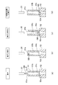
- FIG. 1 is a schematic diagram of an optical element manufacturing apparatus according to the present embodiment
- FIG. 2 is a diagram illustrating a main part of the optical element manufacturing apparatus according to the present embodiment.
- the optical element manufacturing apparatus according to the present embodiment is suitable for forming a lens as an optical element.
- the optical element manufacturing apparatus includes a molten glass supply unit GS that supplies a molten glass droplet GD to a lower mold 30 and a pair of upper and lower molds 30 and 40. And a press molding part PM for press-molding GD.
- the molten glass supply unit GS includes a nozzle 20 provided at the bottom of a melting tank (not shown) that holds heated and melted glass, and drops molten glass droplets GD from the lower end, and a molten glass droplet that naturally falls from the lower end of the nozzle 20. And a holding unit 50 that temporarily holds the GD.
- a heater, a high-frequency coil, an infrared lamp, or the like can be used.
- high-frequency heating is effective.
- the holding part 50 has a hollow cylindrical converging member 51 and a holding member 52 arranged below the converging member.
- the converging member 51 includes an inlet 51a that receives the molten glass droplet GD dropped from the nozzle 20, a passage 51b that is a cylindrical surface through which the glass droplet that has entered from the inlet 51a passes, and an outlet 51c that discharges the glass droplet GD.
- the inner peripheral surface of the passage 51b is a simple cylindrical surface, but a spiral groove may be formed here.
- the holding member 52 has a funnel-shaped receiving portion 52a whose diameter is expanded upward, and has a function of blowing a high-temperature air flow supplied from the outside from below to hold the glass droplet GD in a non-contact manner.
- a holding member is described in, for example, Japanese Patent Application Laid-Open No. 2004-231494.
- the optical element manufacturing apparatus As shown in FIG. 1A, when the molten glass GD is supplied to the lower end of the nozzle 20, the supplied molten glass GD starts growing while staying at the lower end of the nozzle 20, but at the time when it has grown to a predetermined weight.
- the molten glass droplet GD naturally falls by its own weight.
- the glass drop GD that has fallen naturally changes from a spherical shape to a tear shape due to its surface tension, passes through the converging member 51, is controlled in its discharge position, and is discharged into the receiving portion 52 a of the holding member 52.
- the glass droplet GD is trimmed and appropriately cooled while being held in a non-contact manner in the receiving portion 52a. Thereafter, as shown in FIG. 1B, when the holding member 52 holding the glass droplet GD is moved above the lower mold 30 and the air to the receiving portion 52a is stopped, the glass droplet GD is received by the receiving portion 52a. Is discharged from the lower end, and is received as a glass gob on the concave lower mold forming surface 32 of the lower mold 30 at the dropping position.
- the temperature of the lower mold 30 may be room temperature and does not require temperature control. However, when the temperature of the lower mold 30 is too low, wrinkles are likely to occur in the glass gob, so that temperature control by a temperature control device is effective. On the other hand, the upper die 40 also does not require temperature control, but temperature control by a temperature control device is effective.
- heat-resistant materials such as ceramic, cemented carbide, carbon, and metal can be used, but considering the point that the thermal conductivity is good and the reactivity with glass is low, Ceramic is preferred.
- the lower mold 30 that has received the glass droplet GD at the dropping position slides in the horizontal direction to the waiting molding position of the upper mold 40 as shown in FIG.
- the space in which the lower mold 30 moves horizontally between the dripping position and the molding position is surrounded by a mold movement space enclosure (not shown) having heat resistance such as stainless steel, thereby changing the air flow and the temperature resulting therefrom. It is less susceptible to fluctuations. However, such an enclosure may not be provided. Further, the holding member 52 may be moved between the upper mold 40 and the lower mold 30, thereby eliminating the sliding movement of the lower mold 30.
- the upper mold 40 is driven in the vertical direction by press molding means.
- the glass droplet GD placed on the lower mold forming surface 32 of the lower mold 30 is pressure-formed between the lower mold forming surface 32 of the lower mold 30 and the upper mold forming surface 42 of the upper mold 40. Thereafter, the molded lens LS can be taken out by opening the mold. Note that the glass droplet GD may be directly discharged onto the lower mold 30 without using the holding member 52.
- FIG. 1 (e) shows a manufacturing process of the optical element according to the modification.
- the glass droplet GD is supplied directly from the converging member 51 to the lower mold 30.
- the lower mold 30 that has received the glass droplet GD at the dropping position slides horizontally to the molding position where the upper mold 40 is on standby, as shown in FIG.
- FIG. 1 (f) shows a manufacturing process of an optical element according to another modified example.
- a plate member 56 having an opening 56 a is disposed between the converging member 51 and the lower mold 30. Yes.
- the glass droplet GD that naturally falls from the nozzle 20 falls on the upper surface of the plate member 56, but is squeezed when passing through the opening 56 a and falls to the lower mold 30 by an appropriate amount.
- the plate member 56 is described in JP-A-2002-154834.
- the function of the converging member 51 will be described with reference to FIG.
- the axis of the converging member 51 coincides with the axis of the receiving portion 52 a of the holding member 52.
- the molten glass droplet GD that has grown up to a predetermined weight at the lower end of the nozzle 20 receives a slight external force F due to air convection or fluctuation at the moment when it spontaneously falls due to its own weight.
- F due to air convection or fluctuation at the moment when it spontaneously falls due to its own weight.
- the dropped glass droplet GD immediately enters the passage 51b from the inlet 51a of the converging member 51, as shown in FIG.
- the glass droplet GD passing through the passage 51b is applied with a non-contact force from the wall surface of the passage 51b.
- One of these forces is the air pressure acting between the glass drop GD and the wall surface of the passage 51b while the glass drop GD passes through the passage 51b.
- the glass droplet GD passes through the cylindrical passage 51b, thereby generating a pressure difference due to the air flow rate difference on the side of the glass droplet GD.
- a force for centering the glass droplet GD is generated, and variations in the discharge position of the glass droplet GD, that is, the dropping position can be suppressed.
- the cross section of the passage 51b is preferably axisymmetric, and in particular, when the distance between the surface of the glass droplet GD and the wall surface is a cylindrical shape, variation in dropping position is stable.
- another force to which the glass droplet GD is applied is a repulsive force due to static electricity generated when electric charges having the same sign are charged between the surface of the glass droplet GD and the wall surface of the passage 51b.
- the converging member 51 is made of a nonconductor such as an acrylic, polycarbonate, vinyl chloride tube, glass tube, or quartz tube, for example, it is easily charged with static electricity.
- a nonconductor such as an acrylic, polycarbonate, vinyl chloride tube, glass tube, or quartz tube
- the molten glass passes through the glass droplet GD
- the molten glass is centered in the center due to repulsive force due to static electricity.
- the discharge position of the glass droplet GD that is, the variation in the dropping position can be suppressed.
- the converging member 51 is formed of a metal material such as stainless steel, iron, aluminum, or copper, the same effect can be obtained by charging either positive or negative.
- the passage 51b has a cylindrical shape, it may be difficult to perform initial alignment.
- the cross section of the passage 51b is elliptical, the centering effect in the short axis direction in the cross section is strengthened, while there is a dimensional margin in the long axis direction, so that the initial alignment becomes easy.
- a spiral groove is provided in the passage 51b, since it is axially symmetric, there is no variation in the dropping position, and the spiral groove can be used as an air escape path. In addition, it is effective when a device in which the airflow rises from below is provided, or when the device is used in a device having a lot of disturbance due to the airflow.
- the inner circumferential cross section of the converging member 51 is a polygonal shape
- a measurement window is provided in the member, and the position of the inner surface is measured using laser light or the like. Precise positioning can be performed.
- the inner peripheral surface is a mirror surface, the laser light can be easily reflected, and the position of the glass droplet GD can be measured with higher accuracy.
- the corners release the turbulence of the air flow, and the center of the surface has the effect of rectifying the glass droplet GD. This is effective when a coming device is provided or when the device is used in a device having a lot of disturbance due to airflow.
- the glass droplet GD is centered so as to approach the axis of the converging member 51 while passing through the passage 51b (see FIG. 2C). Accordingly, as shown in FIG. 2D, the glass droplet GD is converged and discharged at a position substantially close to the axis of the converging member 51 when it is discharged from the discharge port 51c of the converging member 51. It will be received by the receiving part 52a of the member 52 in an appropriate position.
- the glass droplet GD may hit the peripheral surface of the receiving portion 52a and be deformed, or dust may be mixed in. Further, even if the dropping position varies greatly as it touches the receiving part 52a, it is preferable that the dropping position is collected as close to the center of the receiving part 52a as possible. This is because deviation from the center of the receiving portion 52a causes a deviation in the flow of air corresponding to the glass droplet GD, and the cooling method of the surface of the glass droplet GD varies depending on the direction. If the cooling method of the surface of the glass droplet GD is biased, variations in the internal stress distribution of the glass droplet GD occur.
- FIG. 3 is a schematic cross-sectional view of a molten glass supply unit GS according to another embodiment.
- a detection device 53 that detects the position of the glass droplet GD dropped from the nozzle 20, an actuator 54 that drives the converging member 51, and a control device that drives and controls the actuator 54 based on a signal from the detection device 53. 55.
- the detection device has an emission part LD that projects the inspection light beam horizontally toward the glass droplet GD dropped from the nozzle 20 and a light receiving unit PD that enters the inspection light beam that has passed through the glass drop GD.
- the actuator 54 can drive the converging member 51 and the holding member 52 in the horizontal direction in synchronization.
- the control device 55 that detects the position of the glass droplet GD immediately before dropping from the nozzle 20 by receiving the inspection light beam and receiving the signal from the light receiving unit PD, Depending on the position of the glass droplet GD immediately before dropping, for example, the actuator 54 drives the converging member 51 and the holding member 52 on the side opposite to the direction of deviation of the glass droplet GD with respect to the axis, thereby making the glass droplet more accurate.
- the GD discharge position can be controlled.
- Such position control of the converging member 51 and the holding member 52 may be performed every time, or may be performed at a predetermined timing according to, for example, the time from the start of manufacturing, the number of shots, or the like.
- the actuator 54 drives the converging member 51 and the lower mold 30 in the horizontal direction in synchronization.
- the glass droplet GD is always aimed by the holding member 52 or the mold 30 by moving and adjusting the holding member 52 or the mold 30 as the droplet receiving member by an amount corresponding to the amount by which the converging member 51 is moved. It becomes possible to dripping at a position with high accuracy. For example, if the detected drop deviation amount is less than 1/3 of the measured drop position variation amount, there is no need to adjust the holding member 52 or the mold 30. When the dripping position deviation amount is 1/3 or more, it is necessary to adjust the movement amount of the holding member 52 or the mold 30 according to the amount of movement of the convergence member 51. By performing such fine adjustment, it becomes possible to drop the hot glass droplet GD with high accuracy at a target position at all times.
- the manufacturing apparatus to which the present invention is applied is an apparatus that handles molten glass, a glass melting furnace, a cooling chiller, an air conditioner, and the like are arranged and operated in the vicinity.
- the surrounding air is likely to be disturbed due to thermal and external factors, and the glass dropping position is changed.
- vibrations and electrical noise due to peripheral devices propagate to the apparatus, and the combined effect of these influences the dropping nozzle and the glass droplet path, and the glass dropping position accuracy is likely to be disturbed. Therefore, in addition to the dripping position being suddenly disturbed, there are cases where the time changes with a long period of several hours to several days or weeks.
- the glass dropping position can always be kept at the target position by moving the converging member according to the change of the dropping position with time.
- FIG. 4 is a diagram illustrating a change in variation in the dropping position depending on the presence or absence of a converging member.
- the diameter of the glass droplet is about ⁇ 7 mm
- the diameter of the converging member passage is ⁇ 9 mm. Therefore, the cross-sectional area ratio A / B of both is about 1.7.
- Comparative Example 1 in FIG. 4 is an example in which a plurality of glass droplets are dropped from a nozzle without providing the converging member of the present invention, and the variation is obtained.
- Comparative Example 2 is an alternative to providing the converging member of the present invention.
- a windbreak (a square cylinder with a side of 100 mm) as described in Japanese Patent Application No. 2007-186357 is provided around the lower part of the nozzle.
- the converging member of the present invention is used. It is an example provided below the nozzle.
- the variation range in terms of area
- the variation range is 1/4 or less compared to Comparative Example 2.
- the dispersion of the dispersion position can be positively reduced by imparting the dispersion of the dispersion to the glass droplet.
- FIG. 5 is a diagram showing a variation in the variation of the dropping position when the converging member is moved in the horizontal XY direction.
- it has been difficult to drop a molten glass drop close to 1000 ° C. to an arbitrary position.
- the present invention it is possible to drop a glass droplet that has been heated and melted to an arbitrary position.
- FIG. 5 when the converging member is moved by ⁇ 2.5 mm only in the X direction, and when the converging member is moved by ⁇ 1.5 mm in the X direction and +1.0 mm in the Y direction, compared to the case where the converging member is not moved, No increase in variability was observed. That is, by moving the converging member, it is possible to arbitrarily move the dropping position while maintaining the range of variation.
- the optical element is not limited to a lens.
Landscapes
- Chemical & Material Sciences (AREA)
- Engineering & Computer Science (AREA)
- Materials Engineering (AREA)
- Organic Chemistry (AREA)
- Casting Or Compression Moulding Of Plastics Or The Like (AREA)
- Surface Treatment Of Glass (AREA)
- Optical Measuring Cells (AREA)
Abstract
Description
前記通路を通過するガラス滴は、前記通路の壁面より非接触で所定の力を付与されることにより前記排出口から排出される位置を制御されることを特徴とする。
1.1<A/B<100 (1)
1.3<A/B<10 (1’)
ノズルから滴下する溶融したガラス滴を、収斂部材を介して所定位置に排出させるステップと、
ノズルから滴下する溶融したガラス滴の位置を検出するステップと、
検出された前記ノズルから滴下するガラス滴の位置に応じて、前記収斂部材を前記ガラス滴の落下方向に対して交差する方向に移動させるステップとを有することを特徴とする。
本発明によれば、突発的な変化に加えて、経時的な滴下位置の変化に応じて収斂部材を移動することで常に狙いとする位置にガラス滴下位置を保つことができる。
ΔY=A・ΔX (2)
但し、
ΔY:ガラス滴の排出位置のシフト量
ΔX:収斂部材の移動量
A:係数(0.2~0.8)
30 下型
32 下型成形面
40 上型
42 上型成形面
50 保持部
51 収斂部材
51 通路
51a 入口
51b 通路
51c 排出口
52 保持部材
52a 受け部
53 検出装置
54 アクチュエータ
55 制御装置
GD ガラス滴
GS 溶融ガラス供給部
LD 出射部
PD 受光部
PM プレス成形部
Claims (12)
- ノズルから滴下する溶融したガラス滴を受ける入口と、前記入口から侵入した前記ガラス滴が通過する通路と、前記ガラス滴が排出される排出口とを有する収斂部材を有し、
前記通路を通過するガラス滴は、前記通路の壁面より非接触で所定の力を付与されることにより前記排出口から排出される位置を制御されることを特徴とする光学素子の製造装置。 - 前記所定の力とは、前記ガラス滴が前記通路を通過する間に、前記ガラス滴と前記通路の壁面との間に作用する空気圧であることを特徴とする請求項1に記載の光学素子の製造装置。
- 前記所定の力とは、前記ガラス滴が前記通路を通過する間に、前記ガラス滴と前記通路の壁面との間に作用する静電気力であることを特徴とする請求項1又は2に記載の光学素子の製造装置。
- 前記通路の断面積をA、前記ガラス滴の最大断面積をBとしたときに、以下の式を満たすことを特徴とする請求項1~3のいずれかに記載の光学素子の製造装置。
1.1<A/B<100 (1) - 前記ノズルから滴下するガラス滴の位置を検出する検出装置を有し、前記検出装置が検出した前記ノズルから滴下するガラス滴の位置に応じて、前記収斂部材を前記ガラス滴の落下方向に対して交差する方向に移動させることを特徴とする請求項1~4のいずれかに記載の光学素子の製造装置。
- 前記収斂部材は樹脂、ガラス、金属、セラミックのいずれかより形成されていることを特徴とする請求項1~5のいずれかに記載の光学素子の製造装置。
- 前記収斂部材の内周面は円筒状であることを特徴とする請求項1~6のいずれかに記載の光学素子の製造装置。
- 前記収斂部材の内周面に螺旋状の溝が形成されていることを特徴とする請求項7に記載の光学素子の製造装置。
- 前記収斂部材の内周面は多角形状であることを特徴とする請求項1~6のいずれかに記載の光学素子の製造装置。
- ノズルから滴下する溶融したガラス滴を、収斂部材を介して所定位置に排出させるステップと、
ノズルから滴下する溶融したガラス滴の位置を検出するステップと、
検出された前記ノズルから滴下するガラス滴の位置に応じて、前記収斂部材を前記ガラス滴の落下方向に対して交差する方向に移動させるステップと、を有することを特徴とする光学素子の製造方法。 - 前記収斂部材の移動は、前記ノズルから最初にガラス滴が滴下したときから、所定時間経過後、又は所定数の滴下が行われた後に、実行されることを特徴とする請求項10に記載の光学素子の製造方法。
- 前記収斂部材の移動量に応じて、滴受け部材もしくは金型を移動させることを特徴とする請求項10又は11に記載の光学素子の製造方法。
Priority Applications (3)
| Application Number | Priority Date | Filing Date | Title |
|---|---|---|---|
| CN201280028666.7A CN103827049B (zh) | 2011-06-15 | 2012-06-06 | 光学元件的制造装置及光学元件的制造方法 |
| JP2013520514A JP5888328B2 (ja) | 2011-06-15 | 2012-06-06 | 光学素子の製造装置及び光学素子の製造方法 |
| US14/126,160 US20140116089A1 (en) | 2011-06-15 | 2012-06-06 | Apparatus for Manufacturing Optical Element and Method of Manufacturing Optical Element |
Applications Claiming Priority (2)
| Application Number | Priority Date | Filing Date | Title |
|---|---|---|---|
| JP2011132902 | 2011-06-15 | ||
| JP2011-132902 | 2011-06-15 |
Publications (1)
| Publication Number | Publication Date |
|---|---|
| WO2012173025A1 true WO2012173025A1 (ja) | 2012-12-20 |
Family
ID=47357014
Family Applications (1)
| Application Number | Title | Priority Date | Filing Date |
|---|---|---|---|
| PCT/JP2012/064557 Ceased WO2012173025A1 (ja) | 2011-06-15 | 2012-06-06 | 光学素子の製造装置及び光学素子の製造方法 |
Country Status (4)
| Country | Link |
|---|---|
| US (1) | US20140116089A1 (ja) |
| JP (1) | JP5888328B2 (ja) |
| CN (1) | CN103827049B (ja) |
| WO (1) | WO2012173025A1 (ja) |
Families Citing this family (3)
| Publication number | Priority date | Publication date | Assignee | Title |
|---|---|---|---|---|
| JP6566760B2 (ja) * | 2015-07-22 | 2019-08-28 | キヤノン株式会社 | 光学部品、光学部品の製造方法およびカメラ |
| US11912608B2 (en) | 2019-10-01 | 2024-02-27 | Owens-Brockway Glass Container Inc. | Glass manufacturing |
| AU2021353514B2 (en) | 2020-09-30 | 2026-04-02 | Owens-Brockway Glass Container Inc. | Molten glass feeding and molding |
Citations (2)
| Publication number | Priority date | Publication date | Assignee | Title |
|---|---|---|---|---|
| JPH05301719A (ja) * | 1992-04-24 | 1993-11-16 | Olympus Optical Co Ltd | 溶融ガラスゴブの供給方法 |
| WO2011018940A1 (ja) * | 2009-08-12 | 2011-02-17 | コニカミノルタオプト株式会社 | ガラスゴブの製造方法及びガラス成形体の製造方法 |
Family Cites Families (6)
| Publication number | Priority date | Publication date | Assignee | Title |
|---|---|---|---|---|
| JPS5929529B2 (ja) * | 1977-09-20 | 1984-07-21 | 東芝硝子株式会社 | 硝子種子塊の供給方法 |
| DE60238412D1 (de) * | 2001-07-19 | 2011-01-05 | Nihon Yamamura Glass Co Ltd | Verfahren zur qualitätskontrolle von glastropfen und qualitätskontrollvorrichtung bei einem glasartikelformgebungsverfahren |
| JP4288951B2 (ja) * | 2003-01-31 | 2009-07-01 | コニカミノルタホールディングス株式会社 | 搬送装置、光学素子の製造装置、及び光学素子の製造方法 |
| JP4318542B2 (ja) * | 2003-12-22 | 2009-08-26 | 株式会社オハラ | 球状ガラス製造装置及び球状ガラスの製造方法 |
| US20060042314A1 (en) * | 2004-08-27 | 2006-03-02 | Abbott John S Iii | Noncontact glass sheet stabilization device used in fusion forming of a glass sheet |
| JP4835162B2 (ja) * | 2006-01-11 | 2011-12-14 | コニカミノルタオプト株式会社 | 光学素子の製造方法及び光学素子の製造装置 |
-
2012
- 2012-06-06 US US14/126,160 patent/US20140116089A1/en not_active Abandoned
- 2012-06-06 WO PCT/JP2012/064557 patent/WO2012173025A1/ja not_active Ceased
- 2012-06-06 CN CN201280028666.7A patent/CN103827049B/zh active Active
- 2012-06-06 JP JP2013520514A patent/JP5888328B2/ja not_active Expired - Fee Related
Patent Citations (2)
| Publication number | Priority date | Publication date | Assignee | Title |
|---|---|---|---|---|
| JPH05301719A (ja) * | 1992-04-24 | 1993-11-16 | Olympus Optical Co Ltd | 溶融ガラスゴブの供給方法 |
| WO2011018940A1 (ja) * | 2009-08-12 | 2011-02-17 | コニカミノルタオプト株式会社 | ガラスゴブの製造方法及びガラス成形体の製造方法 |
Also Published As
| Publication number | Publication date |
|---|---|
| JPWO2012173025A1 (ja) | 2015-02-23 |
| JP5888328B2 (ja) | 2016-03-22 |
| US20140116089A1 (en) | 2014-05-01 |
| CN103827049B (zh) | 2016-12-21 |
| CN103827049A (zh) | 2014-05-28 |
Similar Documents
| Publication | Publication Date | Title |
|---|---|---|
| JP2010254569A (ja) | 熱調節によるガラス流管理 | |
| CN108495825B (zh) | 热稳定的玻璃管成形设备和方法 | |
| JP5888328B2 (ja) | 光学素子の製造装置及び光学素子の製造方法 | |
| CN1867520B (zh) | 用于制造管材的装置和方法 | |
| CN102887622B (zh) | 用于制造具有预定内型面的玻璃管的方法和设备 | |
| KR20160014608A (ko) | 유리 리본을 제조하기 위한 방법 및 장치 | |
| US20070204654A1 (en) | Method and apparatus for manufacturing optical element | |
| TWI410387B (zh) | 熔融物流出噴嘴 | |
| JP5263163B2 (ja) | ガラス成形体の製造方法 | |
| CN100422100C (zh) | 玻璃成形体及光学元件的制造方法、熔融玻璃流出装置及玻璃成形体的制造装置 | |
| US5738701A (en) | Glass gob production device and production method | |
| TWI415804B (zh) | 玻璃製預製件群、玻璃製預製件群之製造方法以及光學元件之製造方法 | |
| JP2015074574A (ja) | 板ガラスの製造方法 | |
| US6499316B2 (en) | Method of producing a glass gob, method of producing a glass molded product, and apparatus for producing a glass gob | |
| US20200247703A1 (en) | Dropping nozzle and molding apparatus | |
| JP5932846B2 (ja) | ガラス塊の製造方法、及びガラス塊の成形装置、並びにプレス成形用素材、ガラス成形品、球プリフォーム、及び光学素子の製造方法 | |
| JPWO2009122949A1 (ja) | 光学素子の製造方法及び光学素子の製造装置 | |
| CN1958487B (zh) | 玻璃制预成形件组、玻璃制预成形件的制造方法、光学元件的生产方法 | |
| JP2000233934A (ja) | ガラス製品のプレス成形方法及び装置 | |
| JP5243723B2 (ja) | ノズル及びそのノズルを使用した光学ガラス塊の製造方法 | |
| TW202128576A (zh) | 製造玻璃帶之方法及設備 | |
| JP2004284847A (ja) | ガラス塊の製造方法、及び光学素子の製造方法 | |
| JP2009511406A (ja) | 低粘度溶融ガラスを小さな分割部分に正確に分割する方法及び装置 | |
| JPH06206730A (ja) | ガラスゴブの製造方法 | |
| JP2015145316A (ja) | ノズル及びそのノズルを用いた光学ガラス塊の製造方法 |
Legal Events
| Date | Code | Title | Description |
|---|---|---|---|
| 121 | Ep: the epo has been informed by wipo that ep was designated in this application |
Ref document number: 12799921 Country of ref document: EP Kind code of ref document: A1 |
|
| ENP | Entry into the national phase |
Ref document number: 2013520514 Country of ref document: JP Kind code of ref document: A |
|
| WWE | Wipo information: entry into national phase |
Ref document number: 14126160 Country of ref document: US |
|
| NENP | Non-entry into the national phase |
Ref country code: DE |
|
| 122 | Ep: pct application non-entry in european phase |
Ref document number: 12799921 Country of ref document: EP Kind code of ref document: A1 |