WO2012173006A1 - 太陽電池用封止膜及びこれを用いた太陽電池 - Google Patents
太陽電池用封止膜及びこれを用いた太陽電池 Download PDFInfo
- Publication number
- WO2012173006A1 WO2012173006A1 PCT/JP2012/064354 JP2012064354W WO2012173006A1 WO 2012173006 A1 WO2012173006 A1 WO 2012173006A1 JP 2012064354 W JP2012064354 W JP 2012064354W WO 2012173006 A1 WO2012173006 A1 WO 2012173006A1
- Authority
- WO
- WIPO (PCT)
- Prior art keywords
- sealing film
- solar cell
- side sealing
- surface side
- mass
- Prior art date
- Legal status (The legal status is an assumption and is not a legal conclusion. Google has not performed a legal analysis and makes no representation as to the accuracy of the status listed.)
- Ceased
Links
Images


Classifications
-
- B—PERFORMING OPERATIONS; TRANSPORTING
- B32—LAYERED PRODUCTS
- B32B—LAYERED PRODUCTS, i.e. PRODUCTS BUILT-UP OF STRATA OF FLAT OR NON-FLAT, e.g. CELLULAR OR HONEYCOMB, FORM
- B32B17/00—Layered products essentially comprising sheet glass, or glass, slag, or like fibres
- B32B17/06—Layered products essentially comprising sheet glass, or glass, slag, or like fibres comprising glass as the main or only constituent of a layer, next to another layer of a specific material
- B32B17/10—Layered products essentially comprising sheet glass, or glass, slag, or like fibres comprising glass as the main or only constituent of a layer, next to another layer of a specific material of synthetic resin
- B32B17/10005—Layered products essentially comprising sheet glass, or glass, slag, or like fibres comprising glass as the main or only constituent of a layer, next to another layer of a specific material of synthetic resin laminated safety glass or glazing
- B32B17/1055—Layered products essentially comprising sheet glass, or glass, slag, or like fibres comprising glass as the main or only constituent of a layer, next to another layer of a specific material of synthetic resin laminated safety glass or glazing characterized by the resin layer, i.e. interlayer
- B32B17/10614—Layered products essentially comprising sheet glass, or glass, slag, or like fibres comprising glass as the main or only constituent of a layer, next to another layer of a specific material of synthetic resin laminated safety glass or glazing characterized by the resin layer, i.e. interlayer comprising particles for purposes other than dyeing
- B32B17/10623—Whitening agents reflecting visible light
-
- B—PERFORMING OPERATIONS; TRANSPORTING
- B32—LAYERED PRODUCTS
- B32B—LAYERED PRODUCTS, i.e. PRODUCTS BUILT-UP OF STRATA OF FLAT OR NON-FLAT, e.g. CELLULAR OR HONEYCOMB, FORM
- B32B17/00—Layered products essentially comprising sheet glass, or glass, slag, or like fibres
- B32B17/06—Layered products essentially comprising sheet glass, or glass, slag, or like fibres comprising glass as the main or only constituent of a layer, next to another layer of a specific material
- B32B17/10—Layered products essentially comprising sheet glass, or glass, slag, or like fibres comprising glass as the main or only constituent of a layer, next to another layer of a specific material of synthetic resin
- B32B17/10005—Layered products essentially comprising sheet glass, or glass, slag, or like fibres comprising glass as the main or only constituent of a layer, next to another layer of a specific material of synthetic resin laminated safety glass or glazing
- B32B17/10009—Layered products essentially comprising sheet glass, or glass, slag, or like fibres comprising glass as the main or only constituent of a layer, next to another layer of a specific material of synthetic resin laminated safety glass or glazing characterized by the number, the constitution or treatment of glass sheets
- B32B17/10036—Layered products essentially comprising sheet glass, or glass, slag, or like fibres comprising glass as the main or only constituent of a layer, next to another layer of a specific material of synthetic resin laminated safety glass or glazing characterized by the number, the constitution or treatment of glass sheets comprising two outer glass sheets
-
- B—PERFORMING OPERATIONS; TRANSPORTING
- B32—LAYERED PRODUCTS
- B32B—LAYERED PRODUCTS, i.e. PRODUCTS BUILT-UP OF STRATA OF FLAT OR NON-FLAT, e.g. CELLULAR OR HONEYCOMB, FORM
- B32B17/00—Layered products essentially comprising sheet glass, or glass, slag, or like fibres
- B32B17/06—Layered products essentially comprising sheet glass, or glass, slag, or like fibres comprising glass as the main or only constituent of a layer, next to another layer of a specific material
- B32B17/10—Layered products essentially comprising sheet glass, or glass, slag, or like fibres comprising glass as the main or only constituent of a layer, next to another layer of a specific material of synthetic resin
- B32B17/10005—Layered products essentially comprising sheet glass, or glass, slag, or like fibres comprising glass as the main or only constituent of a layer, next to another layer of a specific material of synthetic resin laminated safety glass or glazing
- B32B17/1055—Layered products essentially comprising sheet glass, or glass, slag, or like fibres comprising glass as the main or only constituent of a layer, next to another layer of a specific material of synthetic resin laminated safety glass or glazing characterized by the resin layer, i.e. interlayer
- B32B17/10678—Layered products essentially comprising sheet glass, or glass, slag, or like fibres comprising glass as the main or only constituent of a layer, next to another layer of a specific material of synthetic resin laminated safety glass or glazing characterized by the resin layer, i.e. interlayer comprising UV absorbers or stabilizers, e.g. antioxidants
-
- B—PERFORMING OPERATIONS; TRANSPORTING
- B32—LAYERED PRODUCTS
- B32B—LAYERED PRODUCTS, i.e. PRODUCTS BUILT-UP OF STRATA OF FLAT OR NON-FLAT, e.g. CELLULAR OR HONEYCOMB, FORM
- B32B17/00—Layered products essentially comprising sheet glass, or glass, slag, or like fibres
- B32B17/06—Layered products essentially comprising sheet glass, or glass, slag, or like fibres comprising glass as the main or only constituent of a layer, next to another layer of a specific material
- B32B17/10—Layered products essentially comprising sheet glass, or glass, slag, or like fibres comprising glass as the main or only constituent of a layer, next to another layer of a specific material of synthetic resin
- B32B17/10005—Layered products essentially comprising sheet glass, or glass, slag, or like fibres comprising glass as the main or only constituent of a layer, next to another layer of a specific material of synthetic resin laminated safety glass or glazing
- B32B17/1055—Layered products essentially comprising sheet glass, or glass, slag, or like fibres comprising glass as the main or only constituent of a layer, next to another layer of a specific material of synthetic resin laminated safety glass or glazing characterized by the resin layer, i.e. interlayer
- B32B17/10788—Layered products essentially comprising sheet glass, or glass, slag, or like fibres comprising glass as the main or only constituent of a layer, next to another layer of a specific material of synthetic resin laminated safety glass or glazing characterized by the resin layer, i.e. interlayer containing ethylene vinylacetate
-
- B—PERFORMING OPERATIONS; TRANSPORTING
- B32—LAYERED PRODUCTS
- B32B—LAYERED PRODUCTS, i.e. PRODUCTS BUILT-UP OF STRATA OF FLAT OR NON-FLAT, e.g. CELLULAR OR HONEYCOMB, FORM
- B32B27/00—Layered products comprising a layer of synthetic resin
- B32B27/06—Layered products comprising a layer of synthetic resin as the main or only constituent of a layer, which is next to another layer of the same or of a different material
-
- B—PERFORMING OPERATIONS; TRANSPORTING
- B32—LAYERED PRODUCTS
- B32B—LAYERED PRODUCTS, i.e. PRODUCTS BUILT-UP OF STRATA OF FLAT OR NON-FLAT, e.g. CELLULAR OR HONEYCOMB, FORM
- B32B27/00—Layered products comprising a layer of synthetic resin
- B32B27/18—Layered products comprising a layer of synthetic resin characterised by the use of special additives
- B32B27/20—Layered products comprising a layer of synthetic resin characterised by the use of special additives using fillers, pigments, thixotroping agents
-
- B—PERFORMING OPERATIONS; TRANSPORTING
- B32—LAYERED PRODUCTS
- B32B—LAYERED PRODUCTS, i.e. PRODUCTS BUILT-UP OF STRATA OF FLAT OR NON-FLAT, e.g. CELLULAR OR HONEYCOMB, FORM
- B32B27/00—Layered products comprising a layer of synthetic resin
- B32B27/30—Layered products comprising a layer of synthetic resin comprising vinyl (co)polymers; comprising acrylic (co)polymers
- B32B27/306—Layered products comprising a layer of synthetic resin comprising vinyl (co)polymers; comprising acrylic (co)polymers comprising vinyl acetate or vinyl alcohol (co)polymers
-
- B—PERFORMING OPERATIONS; TRANSPORTING
- B32—LAYERED PRODUCTS
- B32B—LAYERED PRODUCTS, i.e. PRODUCTS BUILT-UP OF STRATA OF FLAT OR NON-FLAT, e.g. CELLULAR OR HONEYCOMB, FORM
- B32B27/00—Layered products comprising a layer of synthetic resin
- B32B27/32—Layered products comprising a layer of synthetic resin comprising polyolefins
-
- B—PERFORMING OPERATIONS; TRANSPORTING
- B32—LAYERED PRODUCTS
- B32B—LAYERED PRODUCTS, i.e. PRODUCTS BUILT-UP OF STRATA OF FLAT OR NON-FLAT, e.g. CELLULAR OR HONEYCOMB, FORM
- B32B7/00—Layered products characterised by the relation between layers; Layered products characterised by the relative orientation of features between layers, or by the relative values of a measurable parameter between layers, i.e. products comprising layers having different physical, chemical or physicochemical properties; Layered products characterised by the interconnection of layers
- B32B7/04—Interconnection of layers
- B32B7/12—Interconnection of layers using interposed adhesives or interposed materials with bonding properties
-
- H—ELECTRICITY
- H10—SEMICONDUCTOR DEVICES; ELECTRIC SOLID-STATE DEVICES NOT OTHERWISE PROVIDED FOR
- H10F—INORGANIC SEMICONDUCTOR DEVICES SENSITIVE TO INFRARED RADIATION, LIGHT, ELECTROMAGNETIC RADIATION OF SHORTER WAVELENGTH OR CORPUSCULAR RADIATION
- H10F19/00—Integrated devices, or assemblies of multiple devices, comprising at least one photovoltaic cell covered by group H10F10/00, e.g. photovoltaic modules
- H10F19/80—Encapsulations or containers for integrated devices, or assemblies of multiple devices, having photovoltaic cells
- H10F19/804—Materials of encapsulations
-
- B—PERFORMING OPERATIONS; TRANSPORTING
- B32—LAYERED PRODUCTS
- B32B—LAYERED PRODUCTS, i.e. PRODUCTS BUILT-UP OF STRATA OF FLAT OR NON-FLAT, e.g. CELLULAR OR HONEYCOMB, FORM
- B32B2264/00—Composition or properties of particles which form a particulate layer or are present as additives
- B32B2264/10—Inorganic particles
- B32B2264/102—Oxide or hydroxide
-
- B—PERFORMING OPERATIONS; TRANSPORTING
- B32—LAYERED PRODUCTS
- B32B—LAYERED PRODUCTS, i.e. PRODUCTS BUILT-UP OF STRATA OF FLAT OR NON-FLAT, e.g. CELLULAR OR HONEYCOMB, FORM
- B32B2307/00—Properties of the layers or laminate
- B32B2307/40—Properties of the layers or laminate having particular optical properties
- B32B2307/412—Transparent
-
- B—PERFORMING OPERATIONS; TRANSPORTING
- B32—LAYERED PRODUCTS
- B32B—LAYERED PRODUCTS, i.e. PRODUCTS BUILT-UP OF STRATA OF FLAT OR NON-FLAT, e.g. CELLULAR OR HONEYCOMB, FORM
- B32B2307/00—Properties of the layers or laminate
- B32B2307/70—Other properties
- B32B2307/71—Resistive to light or to UV
-
- B—PERFORMING OPERATIONS; TRANSPORTING
- B32—LAYERED PRODUCTS
- B32B—LAYERED PRODUCTS, i.e. PRODUCTS BUILT-UP OF STRATA OF FLAT OR NON-FLAT, e.g. CELLULAR OR HONEYCOMB, FORM
- B32B2457/00—Electrical equipment
-
- B—PERFORMING OPERATIONS; TRANSPORTING
- B32—LAYERED PRODUCTS
- B32B—LAYERED PRODUCTS, i.e. PRODUCTS BUILT-UP OF STRATA OF FLAT OR NON-FLAT, e.g. CELLULAR OR HONEYCOMB, FORM
- B32B2457/00—Electrical equipment
- B32B2457/10—Batteries
-
- Y—GENERAL TAGGING OF NEW TECHNOLOGICAL DEVELOPMENTS; GENERAL TAGGING OF CROSS-SECTIONAL TECHNOLOGIES SPANNING OVER SEVERAL SECTIONS OF THE IPC; TECHNICAL SUBJECTS COVERED BY FORMER USPC CROSS-REFERENCE ART COLLECTIONS [XRACs] AND DIGESTS
- Y02—TECHNOLOGIES OR APPLICATIONS FOR MITIGATION OR ADAPTATION AGAINST CLIMATE CHANGE
- Y02E—REDUCTION OF GREENHOUSE GAS [GHG] EMISSIONS, RELATED TO ENERGY GENERATION, TRANSMISSION OR DISTRIBUTION
- Y02E10/00—Energy generation through renewable energy sources
- Y02E10/50—Photovoltaic [PV] energy
Definitions
- the present invention relates to a solar cell sealing film mainly composed of an ethylene-vinyl acetate copolymer, and a solar cell using the same.
- the solar cell includes a surface side transparent protective member 11 made of a glass substrate or the like, a surface side sealing film 13 ⁇ / b> A, a solar cell 14 such as a silicon power generation element, a back side sealing film 13 ⁇ / b> B, And the back-side protection member 12 are laminated in this order, degassed under reduced pressure, and then heated and pressurized to crosslink and cure the surface-side sealing film 13A and the back-side sealing film 13B to be bonded and integrated.
- the in the conventional solar battery in order to obtain a high electric output, a plurality of solar battery cells 14 electrically connected by the connection tab 15 are connected and used. Therefore, in order to ensure insulation between the solar battery cells 14, the solar battery cells are sealed using the sealing films 13A and 13B having insulation properties.
- the solar battery cells 14 are temporarily fixed with the cell stopper tape 16 (Patent Document 1). ).
- the cell 14 for solar cells can be arrange
- the cell stopper tape 16 a PET film provided with an adhesive layer is generally used because it is inexpensive and excellent in transparency.
- sealing films 13A and 13B are inexpensive and have high transparency and adhesiveness
- ethylene-vinyl acetate copolymer (EVA) films have been conventionally used.
- EVA film for sealing film has high adhesion and adhesion strength to ensure mechanical durability of solar cell and prevent rusting of internal conductors and electrodes due to moisture or water permeation. Therefore, the function of bonding and integrating the members is necessary.
- the EVA film is produced by depositing a composition containing an ethylene-vinyl acetate copolymer and a crosslinking agent.
- a cross-linking agent such as an organic peroxide
- the solar cell sealing film on the surface side is preferably as transparent as possible, and does not absorb or reflect incident sunlight and transmits most of sunlight.
- Patent Document 2 attempts to prevent yellowing by reducing the content of the ultraviolet absorber (0.01% by weight or less based on the weight of the sealing film).
- an object of the present invention is a surface-side sealing film used for a solar battery in which a solar cell is temporarily fixed with a cell-stopping tape at a predetermined position, and the surface-side sealing film and the yellow of the cell-stopping tape are used.
- An object of the present invention is to provide a solar cell surface side sealing film in which alteration is prevented, crosslinking speed is good, and foaming is suppressed.
- an object of the present invention is to provide a solar cell in which power generation efficiency is improved and appearance defects are prevented by using the surface side sealing film.
- the present inventors have found that the above objects are a surface-side transparent protective member, a surface-side sealing film, a solar cell, a back-side sealing.
- the solar battery cell is sealed by cross-linking and integrating the laminated body in which the stop film and the back surface side protective member are laminated in this order, and the solar battery cell is temporarily fixed at a predetermined position with the cell stopper tape.
- the surface side sealing film used for the solar cell formed An ethylene-vinyl acetate copolymer, a crosslinking agent and an ultraviolet absorber, wherein the crosslinking agent is 2,5-dimethyl-2,5-di (t-butylperoxy) hexane, and the ethylene-vinyl acetate copolymer 1.2 to 2.5 parts by mass with respect to 100 parts by mass of the polymer, and the ultraviolet absorber is 2-hydroxy-4-n-octoxybenzophenone, and with respect to 100 parts by mass of the ethylene-vinyl acetate copolymer
- the present invention has been found to be achieved by a solar cell surface side sealing film characterized by containing 0.015 to 0.05 parts by mass.
- the object is to laminate the surface side transparent protective member, the surface side sealing film, the solar cell, the back side sealing film, and the back side protective member in this order, and the solar cell is in a predetermined position.
- a solar battery formed by sealing the solar battery cell by cross-linking the laminate temporarily fixed with the cell fastening tape to the solar battery surface side as the surface sealing film It is also achieved by a solar cell characterized by using a sealing film.
- Preferred embodiments of the solar cell according to the present invention are as follows.
- Yellowness of cell stopper tape measured according to JIS-K-7105 (1981) when a metal halide lamp is used as a light source and irradiated with ultraviolet rays at an irradiation intensity of 1000 W / m 2 for 24 hours ( ⁇ YI) is 4 or less. If the yellowing degree exceeds 4, the yellowness of the cell-stopping tape can be visually recognized.
- the cell stopper tape is a tape having an adhesive layer on the surface of the polyethylene terephthalate film.
- the back side sealing film contains an ethylene-vinyl acetate copolymer, a crosslinking agent and a colorant.
- the back side sealing film contains an ethylene-vinyl acetate copolymer, a crosslinking agent, and an ultraviolet absorber, and the ultraviolet absorber is 0.2 parts per 100 parts by mass of the ethylene-vinyl acetate copolymer. Including 0.5 parts by mass.
- the surface side sealing film according to the present invention yellowing of the surface side sealing film and the cell stopper tape can be effectively prevented by using the above combination and addition amount of the crosslinking agent and the ultraviolet absorber.
- the crosslinking rate becomes good and foaming can be prevented. That is, by using an appropriate amount of the ultraviolet absorber, yellowing of the surface side sealing film and the cell stopper tape is prevented, while the content of the crosslinking agent is within a range where yellowing of the surface side sealing film does not occur. Since it can be increased, a reduction in the crosslinking rate and foaming are prevented.
- the sealing film specified above as the back surface side sealing film yellowing of the back surface side protection member can be prevented, and further, the power generation efficiency of the solar cell can be improved.
- the surface-side sealing film according to the present invention is 1.2 to 2.5 parts by mass of 2,5-dimethyl-2,5-5-100 parts by mass of the ethylene-vinyl acetate copolymer.
- Di (t-butylperoxy) hexane hereinafter also referred to as crosslinking agent A
- 0.015-0.05 parts by mass of 2-hydroxy-4-n-octoxybenzophenone hereinafter also referred to as ultraviolet absorber A
- the back side sealing film used in the solar cell according to the present invention contains an ethylene-vinyl acetate copolymer as a main component, and contains a crosslinking agent, a colorant and / or an ultraviolet absorber.
- the front side sealing film and the back side sealing film are made of an ethylene-vinyl acetate copolymer (also referred to as EVA) as a main component, are inexpensive, and have excellent processability and flexibility. Can be formed.
- EVA ethylene-vinyl acetate copolymer
- the content of vinyl acetate in the ethylene-vinyl acetate copolymer is 20 to 35% by mass, more preferably 22 to 30% by mass, especially 24 to 28% by mass based on the mass of the ethylene-vinyl acetate copolymer. Is preferred. If the vinyl acetate content is less than 20% by mass, the fluidity of the composition for sealing film may be lowered, and the processability of the sealing film may be reduced. If the content exceeds 35% by mass, carboxylic acid, Alcohol, amine, or the like may be generated, and foaming may easily occur at the interface between the sealing film and the protective member.
- the front side sealing film and the back side sealing film are made of polyvinyl acetal resin (for example, polyvinyl formal, polyvinyl butyral (PVB resin), modified PVB), and vinyl chloride resin. It may be used as a secondary. In that case, PVB is particularly preferable.
- polyvinyl acetal resin for example, polyvinyl formal, polyvinyl butyral (PVB resin), modified PVB
- PVB is particularly preferable.
- 2,5-dimethyl-2,5-di (t-butylperoxy) hexane is an organic peroxide classified as a dialkyl peroxide organic peroxide, and the structure thereof is represented by the following formula (I):
- the crosslinking agent A is used in an amount of 1.2 to 2.5 parts by mass, preferably 1.3 to 2.0 parts by mass with respect to 100 parts by mass of the ethylene-vinyl acetate copolymer. If the amount is less than 1.2 parts by mass, the crosslinking rate may be reduced. If the amount is more than 2.5 parts by mass, the surface side sealing film may be yellowed or foamed in the crosslinking stage.
- the ultraviolet absorber A is used in an amount of 0.015 to 0.05 parts by mass, preferably 0.02 to 0.05 parts by mass with respect to 100 parts by mass of the ethylene-vinyl acetate copolymer.
- the amount is less than 0.015 parts by mass, the cell stopper tape may be yellowed.
- the amount is more than 0.05 parts by mass, the surface side sealing film may be yellowed.
- Examples of the colorant that can be used include white pigments such as titanium dioxide (titanium white) and calcium carbonate; blue pigments such as ultramarine; black pigments such as carbon black; milky white pigments such as glass beads and light diffusing agents. .
- white pigments such as titanium dioxide (titanium white) and calcium carbonate
- blue pigments such as ultramarine
- black pigments such as carbon black
- milky white pigments such as glass beads and light diffusing agents.
- a white pigment is preferable, and titanium dioxide is particularly preferable.
- the average particle size of these pigments is 200 to 250 nm, preferably 200 to 230 nm. By using fine particles in this range, the reflectance in the wavelength region (particularly 300 to 400 nm) in the ultraviolet region can be improved.
- the average particle diameter is a number average obtained by observing the sealing film with an electron microscope (preferably a transmission electron microscope) at a magnification of about 1,000,000 times, and determining the projected area circle equivalent diameter of at least 100 colorant fine particles. Value.
- the content of the colorant is generally 2 to 10 parts by weight, preferably 3 to 6 parts by weight with respect to 100 parts by weight of the ethylene-vinyl acetate copolymer used for the back side sealing film. If the addition amount is within this range, the reflectivity and workability will be good.
- the ultraviolet absorber used for the back side sealing film is not particularly limited, but 2-hydroxy-4-methoxybenzophenone, 2-hydroxy-4-n-dodecyloxybenzophenone, 2,4-dihydroxybenzophenone, 2, Preferred examples include benzophenone ultraviolet absorbers such as 2'-dihydroxy-4-methoxybenzophenone and 2-hydroxy-4-n-octoxybenzophenone. In particular, 2-hydroxy-4-n-octoxybenzophenone is preferred.
- the blending amount of the ultraviolet absorber is 0.2 to 0.5 parts by mass, preferably 0.2 to 0.4 parts by mass, with respect to 100 parts by mass of the ethylene-vinyl acetate copolymer.
- the ultraviolet absorptivity may be reduced, and the amount of ultraviolet rays transmitted to the back surface side protective member (back sheet) may be increased to cause yellowing. If the amount is more than 0.5 parts by mass, yellowing of the back side sealing film may occur.
- These ultraviolet absorbers can be used alone or in combination of two or more.
- the back side sealing film may contain both a colorant and an ultraviolet absorber.
- Back surface protective member that can be caused by an increase in ultraviolet light transmittance due to a decrease in the amount of ultraviolet absorber blended in the front surface side sealing film by blending the back surface side sealing film with the above amount of the ultraviolet absorber. ) Can be prevented from yellowing.
- the crosslinking agent used for the back side sealing film is capable of forming a crosslinked structure of an ethylene-vinyl acetate copolymer.
- an organic peroxide or a photopolymerization initiator is preferably used.
- Any organic peroxide may be used as long as it decomposes at a temperature of 100 ° C. or higher and generates radicals.
- the organic peroxide is generally selected in consideration of the film formation temperature, the adjustment conditions of the composition, the curing temperature, the heat resistance of the adherend, and the storage stability. In particular, those having a decomposition temperature of 70 hours or more with a half-life of 10 hours are preferred.
- organic peroxide examples include, from the viewpoint of processing temperature and storage stability of the resin, for example, benzoyl peroxide curing agent, tert-hexyl peroxypivalate, tert-butyl peroxypivalate, 3, 5, 5- Trimethylhexanoyl peroxide, di-n-octanoyl peroxide, lauroyl peroxide, stearoyl peroxide, 1,1,3,3-tetramethylbutylperoxy-2-ethylhexanoate, succinic acid peroxide, 2,5-dimethyl-2,5-di (tert-butylperoxy) hexane, 2,5-dimethyl-2,5-di (2-ethylhexanoylperoxy) hexane, 1-cyclohexyl-1-methylethyl Peroxy-2-ethylhexanoate, tert-hexylpa Oxy-2-ethylhexano
- benzoyl peroxide-based curing agent any can be used as long as it decomposes at a temperature of 70 ° C. or higher to generate radicals, and those having a decomposition temperature of 50 hours or higher with a half-life of 10 hours are preferable, It can be appropriately selected in consideration of preparation conditions, film formation temperature, curing (bonding) temperature, heat resistance of the adherend, and storage stability.
- Usable benzoyl peroxide curing agents include, for example, benzoyl peroxide, 2,5-dimethylhexyl-2,5-bisperoxybenzoate, p-chlorobenzoyl peroxide, m-toluoyl peroxide, 2, Examples include 4-dichlorobenzoyl peroxide and t-butyl peroxybenzoate.
- the benzoyl peroxide curing agent may be used alone or in combination of two or more.
- organic peroxides examples include 2,5-dimethyl-2,5-di (tert-butylperoxy) hexane and 1,1-bis (tert-hexylperoxy) -3,3,5-trimethylcyclohexane. preferable. Thereby, foaming is suppressed and the solar cell sealing film which has the outstanding insulation is obtained.
- the content of the organic peroxide used for the back side sealing film is preferably 0.1 to 5 parts by mass, more preferably 0.2 to 3 parts by mass with respect to 100 parts by mass of the ethylene-vinyl acetate copolymer. Part. If the content of the organic peroxide is small, the crosslinking speed may be reduced during the crosslinking and curing, and if it is large, the compatibility with the copolymer may be deteriorated.
- any known photopolymerization initiator can be used, but a photopolymerization initiator having good storage stability after blending is desirable.
- Examples of such a photopolymerization initiator include 2-hydroxy-2-methyl-1-phenylpropan-1-one, 1-hydroxycyclohexyl phenyl ketone, and 2-methyl-1- (4- (methylthio) phenyl).
- Acetophenone series such as -2-morpholinopropane-1
- benzoin series such as benzyldimethyl ketal
- benzophenone series such as benzophenone, 4-phenylbenzophenone, hydroxybenzophenone, thioxanthone series such as isopropylthioxanthone, 2-4-diethylthioxanthone
- methylphenylglyoxylate can be used.
- 2-hydroxy-2-methyl-1-phenylpropan-1-one, 1-hydroxycyclohexyl phenyl ketone, 2-methyl-1- (4- (methylthio) phenyl) -2-morpholinopropane-1 examples include benzophenone.
- photopolymerization initiators may contain one or more known photopolymerization accelerators such as benzoic acid-based or tertiary amine-based compounds such as 4-dimethylaminobenzoic acid, if necessary. Can be mixed and used. Moreover, it can be used individually by 1 type of only a photoinitiator, or 2 or more types of mixture.
- the content of the photopolymerization initiator is preferably 0.5 to 5.0 parts by mass with respect to 100 parts by mass of the ethylene-vinyl acetate copolymer.
- the front surface side sealing film and the back surface side sealing film before cross-linking curing contain a cross-linking aid.
- the crosslinking aid can improve the crosslinking density of the ethylene-vinyl acetate copolymer and improve the adhesion and durability of the sealing film.
- the crosslinking aid is preferably used in an amount of 0.1 to 3.0 parts by mass, more preferably 0.1 to 2.5 parts by mass with respect to 100 parts by mass of the ethylene-vinyl acetate copolymer. With such a content of the crosslinking aid, there is no generation of gas due to the addition of the crosslinking aid, and the crosslinking density of the ethylene-vinyl acetate copolymer can be improved.
- crosslinking aid compound having a radical polymerizable group as a functional group
- examples of the crosslinking aid include trifunctional crosslinking aids such as triallyl cyanurate and triallyl isocyanurate, and (meth) acrylic esters (eg, NK ester). And monofunctional or bifunctional crosslinking aids.
- trifunctional crosslinking aids such as triallyl cyanurate and triallyl isocyanurate, and (meth) acrylic esters (eg, NK ester).
- monofunctional or bifunctional crosslinking aids include triallyl cyanurate and triallyl isocyanurate, and triallyl isocyanurate is particularly preferable.
- the front side sealing film and the back side sealing film contain a silane coupling agent for the purpose of increasing the adhesive force.
- silane coupling agents include ⁇ -methacryloxypropyltrimethoxysilane, ⁇ -methacryloxypropyltriethoxysilane, ⁇ -chloropropylmethoxysilane, vinylethoxysilane, vinyltris ( ⁇ -methoxyethoxy) silane, vinyltriacetoxysilane, ⁇ -glycidoxypropyltrimethoxysilane, ⁇ -glycidoxypropyltriethoxysilane, ⁇ - (3,4-epoxycyclohexyl) ethyltrimethoxysilane, vinyltrichlorosilane, ⁇ -mercaptopropyltrimethoxysilane, ⁇ -amino And propyltriethoxysilane, N- ⁇ - (aminoethy
- ⁇ -methacryloxypropyltrimethoxysilane and ⁇ -methacryloxypropyltriethoxysilane which are silane coupling agents containing a methacryloxy group are preferable, and ⁇ -methacryloxypropyltrimethoxysilane is particularly preferable.
- These silane coupling agents may be used alone or in combination of two or more.
- the content of the silane coupling agent is preferably 0.01 to 5 parts by mass, particularly preferably 0.1 to 2 parts by mass with respect to 100 parts by mass of the ethylene-vinyl acetate copolymer.
- Front side sealing film and back side sealing film improve or adjust various physical properties of the film (optical properties such as mechanical strength and transparency, heat resistance, light resistance, crosslinking speed, etc.), especially mechanical strength.
- various additives such as a plasticizer, an acryloxy group-containing compound, a methacryloxy group-containing compound and / or an epoxy group-containing compound may be further included as necessary.
- the plasticizer is not particularly limited, but polybasic acid esters and polyhydric alcohol esters are generally used. Examples thereof include dioctyl phthalate, dihexyl adipate, triethylene glycol-di-2-ethyl butyrate, butyl sebacate, tetraethylene glycol diptanoate, and triethylene glycol dipelargonate.
- One plasticizer may be used, or two or more plasticizers may be used in combination.
- the plasticizer content is preferably in the range of 5 parts by mass or less with respect to 100 parts by mass of the ethylene-vinyl acetate copolymer.
- the acryloxy group-containing compound and the methacryloxy group-containing compound are generally acrylic acid or methacrylic acid derivatives, and examples thereof include acrylic acid or methacrylic acid esters and amides.
- ester residues include linear alkyl groups such as methyl, ethyl, dodecyl, stearyl, lauryl, cyclohexyl group, tetrahydrofurfuryl group, aminoethyl group, 2-hydroxyethyl group, 3-hydroxypropyl group, Mention may be made of the 3-chloro-2-hydroxypropyl group.
- amides include diacetone acrylamide.
- polyhydric alcohols such as ethylene glycol, triethylene glycol, polypropylene glycol, polyethylene glycol, trimethylolpropane, and pentaerythritol, and esters of acrylic acid or methacrylic acid can also be used.
- epoxy-containing compound examples include triglycidyl tris (2-hydroxyethyl) isocyanurate, neopentyl glycol diglycidyl ether, 1,6-hexanediol diglycidyl ether, allyl glycidyl ether, 2-ethylhexyl glycidyl ether, phenyl glycidyl ether, Mention may be made of phenol (ethyleneoxy) 5 glycidyl ether, pt-butylphenyl glycidyl ether, adipic acid diglycidyl ester, phthalic acid diglycidyl ester, glycidyl methacrylate and butyl glycidyl ether.
- the acryloxy group-containing compound, the methacryloxy group-containing compound, or the epoxy group-containing compound is generally 0.5 to 5.0 parts by mass, particularly 1.0 to 100 parts by mass of the ethylene-vinyl acetate copolymer. It is preferably contained in an amount of ⁇ 4.0 parts by mass.
- front surface side sealing film and the back surface side sealing film may contain a light stabilizer.
- a light stabilizer called a hindered amine type is preferably used.
- LA-52, LA-57, LA-62, LA-63LA-63p, LA-67, LA-68 (all of which are corporations) ADEKA), Tinuvin 744, Tinuvin® 770, Tinuvin® 765, Tinuvin 144, Tinuvin® 622LD, CHIMASSORB® 944LD (all manufactured by Ciba Specialty Chemicals Co., Ltd.), UV-3034 (manufactured by BF Goodrich).
- the light stabilizer may be used alone or in combination of two or more kinds, and the blending amount is 0.01 to 5 parts by mass with respect to 100 parts by mass of the ethylene-vinyl acetate copolymer. It is preferable that
- the front side sealing film and the back side sealing film may contain an anti-aging agent.
- the antioxidant include hindered phenol antioxidants such as N, N′-hexane-1,6-diylbis [3- (3,5-di-tert-butyl-4-hydroxyphenyl) propionamide], Examples thereof include phosphorus heat stabilizers, lactone heat stabilizers, vitamin E heat stabilizers, and sulfur heat stabilizers.
- the composition containing each of the above-described components can be produced by a method of obtaining a sheet-like material by molding by ordinary extrusion molding, calendar molding (calendering) or the like.
- a sheet-like material can be obtained by dissolving the composition in a solvent and coating the solution on a suitable support with a suitable coating machine (coater) and drying to form a coating film.
- the heating temperature during film formation is preferably a temperature at which the crosslinking agent does not react or hardly reacts.
- the temperature is preferably 50 to 90 ° C, particularly 40 to 80 ° C.
- the thickness of the solar cell sealing film of the present invention is not particularly limited, but is 0.05 to 2 mm.
- the structure of the solar cell of the present invention is such that the front-side transparent protective member, the front-side sealing film, the solar cell, the back-side sealing film and the back-side protective member are laminated in this order, and the solar cell is It is a solar cell formed by sealing the solar cell by cross-linking and integrating the laminate temporarily fixed with a cell stopper tape at a predetermined position.
- the side (light-receiving surface side) where the light of the solar cell is irradiated is referred to as “front surface side”
- the surface opposite to the light-receiving surface of the solar cell is referred to as “back surface side”.
- the film 13B and the back surface side protection member 12 may be laminated, and the sealing film may be cross-linked and cured according to a conventional method such as heat and pressure.
- the cell fastening tape 16 is stuck to the adjacent solar cells 14 and temporarily fixed. Note that the plurality of solar cell 14 linked bodies coupled by the connection tab 15 are electrically connected to the adjacent plurality of solar cell 14 linked bodies by the conductive bar 17.
- the laminate is heated with a vacuum laminator at a temperature of 135 to 180 ° C., further 140 to 180 ° C., a degassing time of 0.1 to 5 minutes, and a press pressure of 0.1 to 1.5 kg / cm 2. Heat pressing may be performed at a pressing time of 5 to 15 minutes.
- the ethylene-vinyl acetate copolymer contained in the front side sealing film 13A and the back side sealing film 13B is cross-linked, so that the front side sealing film 13A and the back side sealing film 13B are interposed.
- the surface side transparent protection member 11, the back surface side transparent member 12, and the cell 14 for solar cells can be integrated, and the cell 14 for solar cells can be sealed.
- the surface-side transparent protective member 11 used in the solar cell of the present invention is usually a glass substrate such as silicate glass.
- the thickness of the glass substrate is generally from 0.1 to 10 mm, and preferably from 0.3 to 5 mm.
- the glass substrate may generally be chemically or thermally strengthened.
- the back surface side protective member 12 used in the present invention is preferably a plastic film such as polyethylene terephthalate (PET).
- PET polyethylene terephthalate
- the back side protective member 12 may contain a white pigment. Thereby, the sunlight which permeate
- a plastic film having an adhesive layer formed thereon can be used as the cell stopper tape used in the solar battery of the present invention.
- the plastic film include polyester resins such as polyethylene terephthalate, fluorine resins such as polytetrafluoroethylene, and polyolefin resins such as polyethylene and polypropylene. Of these, polyester resins and fluororesins, particularly polyethylene terephthalate are preferred because of their excellent heat resistance.
- adhesives such as an acrylic type and a silicon type, are mentioned.
- the thickness of the cell stopper tape is generally 10 to 1000 ⁇ m.
- the thickness of the pressure-sensitive adhesive layer of the cell stopper tape is generally about 1 ⁇ 10 2 to 1 ⁇ 10 5 nm.
- the size of the cell stopper tape is not particularly limited as long as it can temporarily fix the cells for solar cells.
- the cell stopper tape is generally shown in FIG. 2 in order to fix the position after laminating the surface side sealing film on the surface side transparent protective member and placing the solar cell in a predetermined position.
- it is used by being attached to the end portion on the back surface side of the adjacent solar cell 14.
- crosslinking is obtained by laminating
- the location where the cell fastening tape is affixed is not limited to the example shown in FIG. 2, and may be any location as long as the solar cell can be fixed at a predetermined position.
- the cell stopper tape attached in this way is visually recognized from the surface side of the solar battery.
- a cell-stopping tape measured according to JIS-K-7105 (1981) when a metal halide lamp is used as a light source and ultraviolet rays are irradiated for 24 hours at an irradiation intensity of 1000 W / m 2 is used. If the yellowing degree ( ⁇ YI) is 4 or less, the yellowness cannot be visually recognized, so that the appearance can be effectively prevented from being deteriorated.
- the solar cell of the present invention is characterized by the sealing film used on the front surface side and the back surface side as described above. Therefore, the members other than the sealing film, such as the front surface side transparent protective member, the back surface side protective member, and the solar cell, the cell stopper tape, or the like only have to have the same configuration as a conventionally known solar cell. There is no particular restriction.
- the yellowness (YI) after ultraviolet irradiation and the yellowness (YI) before irradiation are measured according to JIS-K-7105 (1981) using a color meter (HZ-2, manufactured by Suga Test Instruments Co., Ltd.).
- the yellowing degree ( ⁇ YI), which is the difference, was calculated.
- (3) Crosslink rate (min) The surface-side sealing film prepared above was subjected to a crosslinking reaction at 155 ° C. in an oven, precisely weighed about 1 g at regular intervals, and extracted after 8 hours with hot xylene using a Soxhlet extractor. The gel component was dried at 80 ° C. for 12 hours or more and weighed.
- the mass% of the gel component with respect to the sealing film was calculated, and the crosslinking time when the numerical value reached 80% was defined as the crosslinking rate.
- (4) Yellowing degree of cell stopper tape ( ⁇ YI) As shown in FIG. 3C, the white plate glass 21 / the surface side sealing film 23A / PET26 / the surface side sealing film 23A / the white plate glass 21 are laminated in this order, and the vacuum laminator set at 100 ° C. is used for 10 The laminate obtained by pressurizing for 5 minutes and temporarily pressing was put into an oven set at 155 ° C. and crosslinked for 45 minutes.
- the sample thus obtained was irradiated with ultraviolet rays at an irradiation intensity of 1000 W / m 2 for 24 hours using a metal halide lamp as a light source using an s-UV irradiation tester (eye super UV tester (manufactured by Iwasaki Electric Co., Ltd.)).
- the yellowness (YI) after ultraviolet irradiation and the yellowness (YI) before irradiation are measured according to JIS-K-7105 (1981) using a color meter (HZ-2, manufactured by Suga Test Instruments Co., Ltd.).
- the yellowing degree ( ⁇ YI) which is the difference, was calculated.
- Transmittance (%) at a wavelength of 400 nm of the surface side sealing film As shown in FIG.3 (b), it laminated
- the white plate glass 21 / the front surface side sealing film 23A / the back surface side sealing film 23B / the back surface side protective member 22 are laminated in this order, and the vacuum laminator set at 100 ° C.
- the laminate obtained by pressurizing for 5 minutes and temporarily pressing was put into an oven set at 155 ° C. and crosslinked for 45 minutes.
- the sample thus obtained was irradiated with ultraviolet rays at an irradiation intensity of 1000 W / m 2 for 300 hours using a metal halide lamp as a light source using an s-UV irradiation tester (I Super UV Tester (Iwasaki Electric Co., Ltd.)).
- the yellowness (YI) after ultraviolet irradiation and the yellowness (YI) before irradiation are measured according to JIS-K-7105 (1981) using a color meter (HZ-2, manufactured by Suga Test Instruments Co., Ltd.).
- the yellowing degree ( ⁇ YI), which is the difference, was calculated.
- the laminate obtained by pressurizing with a vacuum laminator set at 100 ° C. for 10 minutes and temporarily bonding was placed in an oven set at 155 ° C. and crosslinked for 45 minutes.
- the reflectance at a wavelength of 300 to 400 nm was measured with a spectrophotometer (manufactured by Hitachi, Ltd .; U-4000).
- a white glass plate was used as the front surface side transparent protective member, white pigment-containing PET was used as the back surface side protective member, and PET was used as the cell stopper tape.
- the dimensions of each member are as follows.
- EVA has a vinyl acetate content of 26% by mass.
- 2 Crosslinking agent A, 2,5-dimethyl-2,5-di (t-butylperoxy) hexane (Perhexa 25B: manufactured by NOF Corporation) * 3: Crosslinking agent B, t-butylperoxy-2-ethylhexyl monocarbonate * 4: Crosslinking aid, triallyl isocyanurate * 5: Adhesion improver, ⁇ -methacryloxypropyltrimethoxysilane * 6: UV absorption Agent A, 2-hydroxy-4-n-octoxybenzophenone (Sumisorb 130, manufactured by Sumitomo Chemical Co., Ltd.) * 7: UV absorber B, 2,2'-dihydroxy-4,4'-dimethoxybenzophenone * 8: White pigment, titanium dioxide fine particles (average particle size: 250 nm) * 9: White pigment, titanium dioxide fine particles (average particle size: 200 nm
- the back side protective member when the amount of the ultraviolet absorber A blended in the back side sealing film was less than 0.2, the back side protective member was yellowed. Further, when the average particle diameter of the white pigment blended in the back side sealing film was 200 nm, the reflectance at 300 to 400 nm was improved.
- the present invention yellowing of the front side sealing film, the cell stopper tape and the back side protective member is prevented, foaming during crosslinking is suppressed, and the crosslinking rate is good, so that the appearance characteristics are high and the productivity is high. It is possible to obtain a solar cell with good power generation efficiency.
Landscapes
- Life Sciences & Earth Sciences (AREA)
- Chemical & Material Sciences (AREA)
- Biochemistry (AREA)
- Photovoltaic Devices (AREA)
- Compositions Of Macromolecular Compounds (AREA)
- Sealing Material Composition (AREA)
- Laminated Bodies (AREA)
Abstract
表面側封止膜及びセル止めテープの黄変が防止され、架橋速度が良好であり、発泡が抑制された太陽電池用表面側封止膜を提供すること。 表面側透明保護部材(11)、表面側封止膜(12)、太陽電池用セル(14)、裏面側封止膜(13A)及び裏面側保護部材(13B)がこの順で積層され、且つ太陽電池用セル(14)が所定の位置にセル止めテープで仮止めされた積層体を、架橋一体化させることにより前記太陽電池用セルを封止してなる太陽電池に使用する前記表面側封止膜であって、EVA、架橋剤及び紫外線吸収剤を含み、前記架橋剤が2,5-ジメチル-2,5-ジ(t-ブチルパーオキシ)ヘキサンであり、前記EVA100質量部に対して1.2~2.5質量部含み、前記紫外線吸収剤が2-ヒドロキシ-4-n-オクトキシベンゾフェノンであり、前記EVA100質量部に対して0.015~0.05質量部含むことを特徴とする表面側太陽電池用封止膜(13A)。
Description
本発明は、エチレン-酢酸ビニル共重合体を主成分とする太陽電池用封止膜、及びこれを用いた太陽電池に関する。
近年、資源の有効利用や環境汚染の防止等の面から、太陽光を電気エネルギーに直接、変換する太陽電池が広く使用され、更に生産性や耐久性の点から開発が進められている。
太陽電池は、例えば、図1に示すように、ガラス基板などからなる表面側透明保護部材11、表面側封止膜13A、シリコン発電素子などの太陽電池用セル14、裏面側封止膜13B、及び裏面側保護部材12をこの順で積層し、減圧で脱気した後、加熱加圧して表面側封止膜13A及び裏面側封止膜13Bを架橋硬化させて接着一体化することにより製造される。従来の太陽電池では、高い電気出力を得るために、接続タブ15により電気的に接続された複数の太陽電池用セル14を接続して用いられている。従って、太陽電池用セル14間の絶縁性を確保するために、絶縁性のある封止膜13A、13Bを用いて太陽電池用セルを封止している。
また、積層時の太陽電池用セルを配置する段階では、図2の説明図に示すように、太陽電池用セル14同士をセル止めテープ16で仮止めすることが行われている(特許文献1)。これにより、太陽電池用セル14を所望とする正確な位置に配置し、配置後の太陽電池用セル14の位置ズレを防止することができる。セル止めテープ16としては安価であり透明性に優れることから一般にPETフィルムに粘着剤層を施したものが用いられている。
また、封止膜13A、13Bには、安価であり高い透明性及び接着性を有することからエチレン-酢酸ビニル共重合体(EVA)フィルムなどが従来から用いられている。封止膜用のEVAフィルムには、太陽電池用セルの機械的な耐久性の確保や、湿気又は水の透過による内部の導線や電極の発錆の防止のため、高度な密着性及び接着強度で各部材を接着一体化させる機能が必要である。
EVAフィルムは、エチレン-酢酸ビニル共重合体および架橋剤などを含む組成物を成膜することで作製される。有機過酸化物等の架橋剤を用いてEVAを架橋させることにより、EVAフィルムの接着性、耐久性を向上させることができる。
また、太陽電池においては、太陽電池に入射した光をできるだけ効率よく太陽電池用セル内に取り込めるようにすることが発電効率の向上の点から望まれている。従って、表面側の太陽電池用封止膜は、できるだけ高い透明性を有し、入射した太陽光を吸収したり、反射したりすることが無く、太陽光のほとんどを透過させるものが望ましい。
しかしながら、太陽電池を長期間使用した場合、太陽光、特に紫外線の影響により、封止膜が黄変して、太陽光の透過率が低下する現象がみられること、及びその黄変による外観不良が問題となっている。この問題のため、従来から封止膜には紫外線吸収剤が添加されている。
しかしながら、架橋剤と紫外線吸収剤の組合せ及び添加量によっては、封止膜に黄変が生じることが知られている(特許文献2)。この問題を解消するため、特許文献2では、紫外線吸収剤の含有量を少なくすることにより(封止膜の重量を基準として0.01重量%以下)黄変の防止が図られている。
特許文献2の技術では、黄変の原因となる紫外線吸収剤の添加量を減量しているので表面側封止膜の黄変は抑制される。しかしながら、紫外線吸収剤の含有量が減少すると表面側封止膜における紫外線の吸収能力が低下して、セル止めテープが紫外線の影響により黄変して外観特性が低下する問題がある。また、架橋剤も封止膜の黄変を引き起こすことが知られており、その配合量によっては隣接する他の部材との界面での発泡や太陽電池の製造段階における架橋速度に影響を与えることとなる。
したがって、本発明の目的は、太陽電池用セルが所定の位置にセル止めテープで仮止めされた太陽電池に使用する表面側封止膜であって、表面側封止膜及びセル止めテープの黄変が防止され、架橋速度が良好であり、発泡が抑制された太陽電池用表面側封止膜を提供することにある。
また、本発明の目的は、上記表面側封止膜を使用することにより発電効率が向上し、外観不良が防止された太陽電池を提供することにある。
本発明者らは、架橋剤と紫外線吸収剤の組み合わせ及び添加量を検討し実験を重ねた結果、上記目的は、表面側透明保護部材、表面側封止膜、太陽電池用セル、裏面側封止膜及び裏面側保護部材がこの順で積層され、且つ太陽電池用セルが所定の位置にセル止めテープで仮止めされた積層体を、架橋一体化させることにより前記太陽電池用セルを封止してなる太陽電池に使用する前記表面側封止膜であって、
エチレン-酢酸ビニル共重合体、架橋剤及び紫外線吸収剤を含み、前記架橋剤が2,5-ジメチル-2,5-ジ(t-ブチルパーオキシ)ヘキサンであり、前記エチレン-酢酸ビニル共重合体100質量部に対して1.2~2.5質量部含み、前記紫外線吸収剤が2-ヒドロキシ-4-n-オクトキシベンゾフェノンであり、前記エチレン-酢酸ビニル共重合体100質量部に対して0.015~0.05質量部含むことを特徴とする太陽電池用表面側封止膜により達成されることを見出した。
エチレン-酢酸ビニル共重合体、架橋剤及び紫外線吸収剤を含み、前記架橋剤が2,5-ジメチル-2,5-ジ(t-ブチルパーオキシ)ヘキサンであり、前記エチレン-酢酸ビニル共重合体100質量部に対して1.2~2.5質量部含み、前記紫外線吸収剤が2-ヒドロキシ-4-n-オクトキシベンゾフェノンであり、前記エチレン-酢酸ビニル共重合体100質量部に対して0.015~0.05質量部含むことを特徴とする太陽電池用表面側封止膜により達成されることを見出した。
また、上記目的は、表面側透明保護部材、表面側封止膜、太陽電池用セル、裏面側封止膜及び裏面側保護部材がこの順で積層され、且つ前記太陽電池用セルが所定の位置にセル止めテープで仮止めされた積層体を、架橋一体化させることにより前記太陽電池用セルを封止してなる太陽電池であって、前記表面側封止膜として、上記太陽電池用表面側封止膜を用いたことを特徴とする太陽電池によっても達成される。
本発明に係る太陽電池の好ましい態様は以下の通りである。
(1)光源としてメタルハライドランプを使用して、紫外線を照射強度1000W/m2で24時間照射した場合の、JIS-K-7105(1981)に準拠して測定したセル止めテープの黄変度(ΔYI)が4以下である。
この黄変度が4を超えるとセル止めテープの黄色味が視認可能となるので、4以下においては太陽電池の外観性の低下を防止することができる。
(2)セル止めテープが、ポリエチレンテレフタレートフィルムの表面に粘着剤層を有するテープである。
(3)裏面側封止膜が、エチレン-酢酸ビニル共重合体、架橋剤及び着色剤を含む。
表面側透明保護部材及び表面側封止膜を透過し、更に太陽電池用セル同士の隙間等から裏面側封止膜に達した紫外線領域の波長を含む太陽光を反射させ、太陽電池用セルに入射させることで発電効率の向上を図ることができる。また、紫外線領域の波長を反射させることで裏面側保護部材へ透過することが防止され、紫外線による裏面側保護部材の黄変を防止することができる。
(4)着色剤が、二酸化チタンである。
太陽光、特に紫外線を良好に反射させることが可能である。
(5)裏面側封止膜が、エチレン-酢酸ビニル共重合体、架橋剤及び紫外線吸収剤を含み、紫外線吸収剤が、前記エチレン-酢酸ビニル共重合体100質量部に対して、0.2~0.5質量部含む。
紫外線を裏面側封止膜で吸収することで紫外線の裏面側保護部材への入射が抑制され、その黄変を防止することができる。
本発明に係る表面側封止膜によれば、架橋剤と紫外線吸収剤の上記組合せ及び添加量とすることにより、表面側封止膜及びセル止めテープの黄変を有効に防止することができ、架橋速度が良好となり、発泡を防止することができる。すなわち、紫外線吸収剤を適量で使用することで表面側封止膜及びセル止めテープの黄変が防止される一方で、表面側封止膜の黄変が生じない範囲で架橋剤の含有量を多くすることができるので、架橋速度の低下及び発泡が防止される。また、裏面側封止膜として、上記規定した封止膜を使用することにより、裏面側保護部材の黄変が防止され、更には太陽電池の発電効率を向上させることも可能となる。
上述したように、本発明に係る表面側封止膜は、エチレン-酢酸ビニル共重合体100質量部に対して、1.2~2.5質量部の2,5-ジメチル-2,5-ジ(t-ブチルパーオキシ)ヘキサン(以下、架橋剤Aとも称する。)及び0.015~0.05質量部の2-ヒドロキシ-4-n-オクトキシベンゾフェノン(以下、紫外線吸収剤Aとも称する。)を含んでいる。また、本発明に係る太陽電池に使用する裏面側封止膜は、エチレン-酢酸ビニル共重合体を主成分とし、架橋剤並びに着色剤及び/又は紫外線吸収剤を含んでいる。
以下、本発明の太陽電池用封止膜及び太陽電池をより詳細に説明する。
[エチレン-酢酸ビニル共重合体]
表面側封止膜及び裏面側封止膜は、エチレン-酢酸ビニル共重合体(EVAとも言う)を主成分とすることで、安価であり、加工性及び柔軟性に優れる太陽電池用封止膜を形成することができる。
表面側封止膜及び裏面側封止膜は、エチレン-酢酸ビニル共重合体(EVAとも言う)を主成分とすることで、安価であり、加工性及び柔軟性に優れる太陽電池用封止膜を形成することができる。
エチレン-酢酸ビニル共重合体における酢酸ビニルの含有量は、前記エチレン-酢酸ビニル共重合体の質量を基準として20~35質量%、さらに22~30質量%、特に24~28質量%とするのが好ましい。酢酸ビニルの含有量が20質量%未満であると、封止膜用組成物の流動性が低くなり、封止膜の加工性が低下する恐れがあり、35質量%を超えると、カルボン酸、アルコール、アミン等が発生し封止膜と保護部材との界面で発泡が生じ易くなる恐れがある。
表面側封止膜及び裏面側封止膜は、エチレン-酢酸ビニル共重合体に加えて、さらにポリビニルアセタール系樹脂(例えば、ポリビニルホルマール、ポリビニルブチラール(PVB樹脂)、変性PVB)、塩化ビニル樹脂を副次的に使用しても良い。その場合、特にPVBが好ましい。
[2,5-ジメチル-2,5-ジ(t-ブチルパーオキシ)ヘキサン(架橋剤A):表面側封止膜用]
2,5-ジメチル-2,5-ジ(t-ブチルパーオキシ)ヘキサンは、ジアルキルパーオキサイド類有機過酸化物に分類される有機過酸化物であり、その構造は、下記式(I)
2,5-ジメチル-2,5-ジ(t-ブチルパーオキシ)ヘキサンは、ジアルキルパーオキサイド類有機過酸化物に分類される有機過酸化物であり、その構造は、下記式(I)
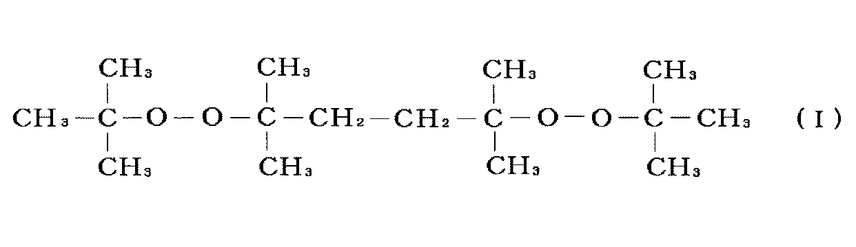
架橋剤Aは、エチレン-酢酸ビニル共重合体100質量部に対して、1.2~2.5質量部、好ましくは1.3~2.0質量部の量で用いる。1.2質量部より少ないと架橋速度が低下する場合があり、2.5質量部より多いと表面側封止膜の黄変や架橋段階での発泡が生じる場合がある。
[2-ヒドロキシ-4-n-オクトキシベンゾフェノン(紫外線吸収剤A):表面側封止膜用]
2-ヒドロキシ-4-n-オクトキシベンゾフェノンは、ベンゾフェノン系紫外線吸収剤に分類され、その構造は、下記式(II)
2-ヒドロキシ-4-n-オクトキシベンゾフェノンは、ベンゾフェノン系紫外線吸収剤に分類され、その構造は、下記式(II)
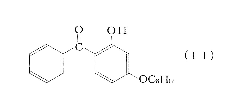
紫外線吸収剤Aは、エチレン-酢酸ビニル共重合体100質量部に対して、0.015~0.05質量部、好ましくは0.02~0.05質量部の量で用いる。0.015質量部より少ないとセル止めテープが黄変する場合があり、0.05質量部より多いと表面側封止膜の黄変が生じる場合がある。
[着色剤:裏面側封止膜用]
裏面側封止膜に着色剤を含有させることにより、表面側封止膜を透過した太陽光、特に紫外線領域の波長を反射させて太陽電池用セルに入射させることで発電効率の向上が図られる。また、裏面側保護部材への紫外線の入射が阻止され、その黄変を防止することができる。
裏面側封止膜に着色剤を含有させることにより、表面側封止膜を透過した太陽光、特に紫外線領域の波長を反射させて太陽電池用セルに入射させることで発電効率の向上が図られる。また、裏面側保護部材への紫外線の入射が阻止され、その黄変を防止することができる。
着色剤としては、二酸化チタン(チタン白)、炭酸カルシウム等による白色顔料;ウルトラマリン等による青色顔料;カーボンブラック等による黒色顔料;ガラスビーズ及び光拡散剤等による乳白色顔料などを使用することができる。この中でも、白色顔料が好ましく、特に二酸化チタンが好ましい。
また、これら顔料の平均粒径は200~250nm、好ましくは200~230nmであることが好ましい。この範囲の微粒子を使用することにより紫外線領域の波長(特に300~400nm)の反射率を向上させることができる。本発明において平均粒径は、封止膜を電子顕微鏡(好ましくは透過型電子顕微鏡)により倍率100万倍程度で観測し、少なくとも100個の着色剤微粒子の投影面積円相当径を求めた数平均値とする。
着色剤の含有量は、裏面側封止膜に使用するエチレン-酢酸ビニル共重合体100重量部に対して、一般に2~10重量部、好ましくは3~6質量部であることが好ましい。この範囲の添加量であれば、反射性及び加工性が良好となる。
[紫外線吸収剤:裏面側封止膜用]
裏面側封止膜に使用する紫外線吸収剤としては、特に制限されないが、2-ヒドロキシ-4-メトキシベンゾフェノン、2-ヒドロキシ-4-n-ドデシロキシベンゾフェノン、2,4-ジヒドロキシベンゾフェノン、2,2'-ジヒドロキシ-4-メトキシベンゾフェノン、2-ヒドロキシ-4-n-オクトキシベンゾフェノン等のベンゾフェノン系紫外線吸収剤が好ましく挙げられる。特に、2-ヒドロキシ-4-n-オクトキシベンゾフェノンが好ましい。紫外線吸収剤の配合量は、エチレン-酢酸ビニル共重合体100質量部に対して0.2~0.5質量部、好ましくは0.2~0.4質量部であることが好ましい。0.2質量部より少ないと紫外線吸収性が低下して裏面側保護部材(バックシート)に透過する紫外線量が増大して黄変が生じる場合がある。0.5質量部より多いと裏面側封止膜の黄変が生じる場合がある。これら紫外線吸収剤は1種単独でも、2種以上を混合しても使用することができる。なお、裏面側封止膜は、着色剤と紫外線吸収剤の両方を含んでいてもよい。
裏面側封止膜に使用する紫外線吸収剤としては、特に制限されないが、2-ヒドロキシ-4-メトキシベンゾフェノン、2-ヒドロキシ-4-n-ドデシロキシベンゾフェノン、2,4-ジヒドロキシベンゾフェノン、2,2'-ジヒドロキシ-4-メトキシベンゾフェノン、2-ヒドロキシ-4-n-オクトキシベンゾフェノン等のベンゾフェノン系紫外線吸収剤が好ましく挙げられる。特に、2-ヒドロキシ-4-n-オクトキシベンゾフェノンが好ましい。紫外線吸収剤の配合量は、エチレン-酢酸ビニル共重合体100質量部に対して0.2~0.5質量部、好ましくは0.2~0.4質量部であることが好ましい。0.2質量部より少ないと紫外線吸収性が低下して裏面側保護部材(バックシート)に透過する紫外線量が増大して黄変が生じる場合がある。0.5質量部より多いと裏面側封止膜の黄変が生じる場合がある。これら紫外線吸収剤は1種単独でも、2種以上を混合しても使用することができる。なお、裏面側封止膜は、着色剤と紫外線吸収剤の両方を含んでいてもよい。
裏面側封止膜に紫外線吸収剤を上記量で配合することにより、表面側封止膜に配合する紫外線吸収剤を少なくしたことによる紫外線透過性の上昇により引き起こされ得る裏面側保護部材(バックシート)が黄変することを防止することができる。
[架橋剤:裏面側封止膜用]
裏面側封止膜に使用する架橋剤は、エチレン-酢酸ビニル共重合体の架橋構造を形成することができるものである。架橋剤は、有機過酸化物又は光重合開始剤を用いることが好ましい。なかでも、接着力、耐湿性、耐貫通性の温度依存性が改善された封止膜が得られることから、有機過酸化物を用いるのが好ましい。
裏面側封止膜に使用する架橋剤は、エチレン-酢酸ビニル共重合体の架橋構造を形成することができるものである。架橋剤は、有機過酸化物又は光重合開始剤を用いることが好ましい。なかでも、接着力、耐湿性、耐貫通性の温度依存性が改善された封止膜が得られることから、有機過酸化物を用いるのが好ましい。
有機過酸化物としては、100℃以上の温度で分解してラジカルを発生するものであれば、どのようなものでも使用することができる。有機過酸化物は、一般に、成膜温度、組成物の調整条件、硬化温度、被着体の耐熱性、貯蔵安定性を考慮して選択される。特に、半減期10時間の分解温度が70℃以上のものが好ましい。
前記有機過酸化物としては、樹脂の加工温度・貯蔵安定性の観点から例えば、ベンゾイルパーオキサイド系硬化剤、tert-ヘキシルパーオキシピバレート、tert-ブチルパーオキシピバレート、3,5,5-トリメチルヘキサノイルパーオキサイド、ジ-n-オクタノイルパーオキサイド、ラウロイルパーオキサイド、ステアロイルパーオキサイド、1,1,3,3-テトラメチルブチルパーオキシ-2-エチルヘキサノエート、スクシニックアシドパーオキサイド、2,5-ジメチル-2,5-ジ(tert-ブチルパーオキシ)ヘキサン、2,5-ジメチル-2,5-ジ(2-エチルヘキサノイルパーオキシ)ヘキサン、1-シクロヘキシル-1-メチルエチルパーオキシ-2-エチルヘキサノエート、tert-ヘキシルパーオキシ-2-エチルヘキサノエート、4-メチルベンゾイルパーオキサイド、tert-ブチルパーオキシ-2-エチルヘキサノエート、m-トルオイル+ベンゾイルパーオキサイド、ベンゾイルパーオキサイド、1,1-ビス(tert-ブチルパーオキシ)-2-メチルシクロヘキサネート、1,1-ビス(tert-ヘキシルパーオキシ)-3,3,5-トリメチルシクロヘキサネート、1,1-ビス(tert-ヘキシルパーオキシ)シクロヘキサネート、1,1-ビス(tert-ブチルパーオキシ)-3,3,5-トリメチルシクロヘキサン、1,1-ビス(tert-ブチルパーオキシ)シクロヘキサン、2,2-ビス(4,4-ジ-tert-ブチルパーオキシシクロヘキシル)プロパン、1,1-ビス(tert-ブチルパーオキシ)シクロドデカン、tert-ヘキシルパーオキシイソプロピルモノカーボネート、tert-ブチルパーオキシマレイックアシド、tert-ブチルパーオキシ-3,3,5-トリメチルヘキサン、tert-ブチルパーオキシラウレート、2,5-ジメチル-2,5-ジ(メチルベンゾイルパーオキシ)ヘキサン、tert-ブチルパーオキシイソプロピルモノカーボネート、tert-ブチルパーオキシ-2-エチルヘキシルモノカーボネート、tert-ヘキシルパーオキシベンゾエート、2,5-ジ-メチル-2,5-ジ(ベンゾイルパーオキシ)ヘキサン、等が挙げられる。
ベンゾイルパーオキサイド系硬化剤としては、70℃以上の温度で分解してラジカルを発生するものであればいずれも使用可能であるが、半減期10時間の分解温度が50℃以上のものが好ましく、調製条件、成膜温度、硬化(貼り合わせ)温度、被着体の耐熱性、貯蔵安定性を考慮して適宜選択できる。使用可能なベンゾイルパーオキサイド系硬化剤としては、例えば、ベンゾイルパーオキサイド、2,5-ジメチルヘキシル-2,5-ビスパーオキシベンゾエート、p-クロロベンゾイルパーオキサイド、m-トルオイルパーオキサイド、2,4-ジクロロベンゾイルパーオキサイド、t-ブチルパーオキシベンゾエート等が挙げられる。ベンゾイルパーオキサイド系硬化剤は1種でも2種以上を組み合わせて使用してもよい。
有機過酸化物として、特に、2,5-ジメチル-2,5-ジ(tert-ブチルパーオキシ)ヘキサン、1,1-ビス(tert-ヘキシルパーオキシ)-3,3,5-トリメチルシクロヘキサンが好ましい。これにより、発泡が抑制され、優れた絶縁性を有する太陽電池用封止膜が得られる。
裏面側封止膜に使用する有機過酸化物の含有量は、エチレン-酢酸ビニル共重合体100質量部に対して、好ましくは0.1~5質量部、より好ましくは0.2~3質量部であることが好ましい。有機過酸化物の含有量は、少ないと架橋硬化時において架橋速度が低下する場合があり、多くなると共重合体との相溶性が悪くなる恐れがある。
また、光重合開始剤としては、公知のどのような光重合開始剤でも使用することができるが、配合後の貯蔵安定性の良いものが望ましい。このような光重合開始剤としては、例えば、2-ヒドロキシ-2-メチル-1-フェニルプロパン-1-オン、1-ヒドロキシシクロヘキシルフェニルケトン、2-メチル-1-(4-(メチルチオ)フェニル)-2-モルホリノプロパン-1などのアセトフェノン系、ベンジルジメチルケタ-ルなどのベンゾイン系、ベンゾフェノン、4-フェニルベンゾフェノン、ヒドロキシベンゾフェノンなどのベンゾフェノン系、イソプロピルチオキサントン、2-4-ジエチルチオキサントンなどのチオキサントン系、その他特殊なものとしては、メチルフェニルグリオキシレ-トなどが使用できる。特に好ましくは、2-ヒドロキシ-2-メチル-1-フェニルプロパン-1-オン、1-ヒドロキシシクロヘキシルフェニルケトン、2-メチル-1-(4-(メチルチオ)フェニル)-2-モルホリノプロパン-1、ベンゾフェノン等が挙げられる。これら光重合開始剤は、必要に応じて、4-ジメチルアミノ安息香酸のごとき安息香酸系又は、第3級アミン系などの公知慣用の光重合促進剤の1種または2種以上を任意の割合で混合して使用することができる。また、光重合開始剤のみの1種単独または2種以上の混合で使用することができる。
前記光重合開始剤の含有量は、エチレン-酢酸ビニル共重合体100質量部に対して0.5~5.0質量部であることが好ましい。
[架橋助剤]
架橋硬化前の表面側封止膜及び裏面側封止膜は、架橋助剤を含んでいることが好ましい。架橋助剤は、エチレン-酢酸ビニル共重合体の架橋密度を向上させ、封止膜の接着性及び耐久性を向上させることができる。
架橋硬化前の表面側封止膜及び裏面側封止膜は、架橋助剤を含んでいることが好ましい。架橋助剤は、エチレン-酢酸ビニル共重合体の架橋密度を向上させ、封止膜の接着性及び耐久性を向上させることができる。
架橋助剤は、エチレン-酢酸ビニル共重合体100質量部に対して、好ましくは0.1~3.0質量部、より好ましくは0.1~2.5質量部で使用される。このような架橋助剤の含有量であれば、架橋助剤の添加によるガスの発生もなく、エチレン-酢酸ビニル共重合体の架橋密度を向上させることができる。
架橋助剤(官能基としてラジカル重合性基を有する化合物)としては、トリアリルシアヌレート、トリアリルイソシアヌレート等の3官能の架橋助剤の他、(メタ)アクリルエステル(例、NKエステル等)の単官能又は2官能の架橋助剤等を挙げることができる。なかでも、トリアリルシアヌレート及びトリアリルイソシアヌレートが好ましく、特にトリアリルイソシアヌレートが好ましい。
[接着性向上剤]
表面側封止膜及び裏面側封止膜は、接着力を高める目的で、シランカップリング剤を含むことが好ましい。シランカップリング剤としては、γ-メタクリロキシプロピルトリメトキシシラン、γ-メタクリロキシプロピルトリエトキシシラン、γ-クロロプロピルメトキシシラン、ビニルエトキシシラン、ビニルトリス(β-メトキシエトキシ)シラン、ビニルトリアセトキシシラン、γ-グリシドキシプロピルトリメトキシシラン、γ-グリシドキシプロピルトリエトキシシラン、β-(3,4-エポキシシクロヘキシル)エチルトリメトキシシラン、ビニルトリクロロシラン、γ-メルカプトプロピルトリメトキシシラン、γ-アミノプロピルトリエトキシシラン、N-β-(アミノエチル)-γ-アミノプロピルトリメトキシシラン等を挙げることができる。この中でも、メタクリロキシ基を含むシランカップリング剤であるγ-メタクリロキシプロピルトリメトキシシラン、γ-メタクリロキシプロピルトリエトキシシランが好ましく、特に、γ-メタクリロキシプロピルトリメトキシシランが好ましい。これらシランカップリング剤は、単独で使用しても、又は2種以上組み合わせて使用しても良い。また、シランカップリング剤の含有量は、エチレン-酢酸ビニル共重合体100質量部に対して0.01~5質量部であることが好ましく、特に0.1~2質量部が好ましい。
表面側封止膜及び裏面側封止膜は、接着力を高める目的で、シランカップリング剤を含むことが好ましい。シランカップリング剤としては、γ-メタクリロキシプロピルトリメトキシシラン、γ-メタクリロキシプロピルトリエトキシシラン、γ-クロロプロピルメトキシシラン、ビニルエトキシシラン、ビニルトリス(β-メトキシエトキシ)シラン、ビニルトリアセトキシシラン、γ-グリシドキシプロピルトリメトキシシラン、γ-グリシドキシプロピルトリエトキシシラン、β-(3,4-エポキシシクロヘキシル)エチルトリメトキシシラン、ビニルトリクロロシラン、γ-メルカプトプロピルトリメトキシシラン、γ-アミノプロピルトリエトキシシラン、N-β-(アミノエチル)-γ-アミノプロピルトリメトキシシラン等を挙げることができる。この中でも、メタクリロキシ基を含むシランカップリング剤であるγ-メタクリロキシプロピルトリメトキシシラン、γ-メタクリロキシプロピルトリエトキシシランが好ましく、特に、γ-メタクリロキシプロピルトリメトキシシランが好ましい。これらシランカップリング剤は、単独で使用しても、又は2種以上組み合わせて使用しても良い。また、シランカップリング剤の含有量は、エチレン-酢酸ビニル共重合体100質量部に対して0.01~5質量部であることが好ましく、特に0.1~2質量部が好ましい。
[その他]
表面側封止膜及び裏面側封止膜は、膜の種々の物性(機械的強度、透明性等の光学的特性、耐熱性、耐光性、架橋速度等)の改良あるいは調整、特に機械的強度の改良のため、必要に応じて、可塑剤、アクリロキシ基含有化合物、メタクリロキシ基含有化合物及び/又はエポキシ基含有化合物などの各種添加剤をさらに含んでいてもよい。
表面側封止膜及び裏面側封止膜は、膜の種々の物性(機械的強度、透明性等の光学的特性、耐熱性、耐光性、架橋速度等)の改良あるいは調整、特に機械的強度の改良のため、必要に応じて、可塑剤、アクリロキシ基含有化合物、メタクリロキシ基含有化合物及び/又はエポキシ基含有化合物などの各種添加剤をさらに含んでいてもよい。
前記可塑剤としては、特に限定されるものではないが、一般に多塩基酸のエステル、多価アルコールのエステルが使用される。その例としては、ジオクチルフタレート、ジヘキシルアジペート、トリエチレングリコール-ジ-2-エチルブチレート、ブチルセバケート、テトラエチレングリコールジプタノエート、トリエチレングリコールジペラルゴネートを挙げることができる。可塑剤は一種用いてもよく、二種以上組み合わせて使用してもよい。可塑剤の含有量はエチレン-酢酸ビニル共重合体100質量部に対して5質量部以下の範囲が好ましい。
前記アクリロキシ基含有化合物及び前記メタクリロキシ基含有化合物としては、一般にアクリル酸あるいはメタクリル酸誘導体であり、例えばアクリル酸あるいはメタクリル酸のエステルやアミドを挙げることができる。エステル残基の例としては、メチル、エチル、ドデシル、ステアリル、ラウリル等の直鎖状のアルキル基、シクロヘキシル基、テトラヒドロフルフリル基、アミノエチル基、2-ヒドロキシエチル基、3-ヒドロキシプロピル基、3-クロロ-2-ヒドロキシプロピル基を挙げることができる。アミドの例としては、ジアセトンアクリルアミドを挙げることができる。また、エチレングリコール、トリエチレングリコール、ポリプロピレングリコール、ポリエチレングリコール、トリメチロールプロパン、ペンタエリスリトール等の多価アルコールとアクリル酸あるいはメタクリル酸のエステルも挙げることができる。
前記エポキシ含有化合物としては、トリグリシジルトリス(2-ヒドロキシエチル)イソシアヌレート、ネオペンチルグリコールジグリシジルエーテル、1,6-ヘキサンジオールジグリシジルエーテル、アリルグリシジルエーテル、2-エチルヘキシルグリシジルエーテル、フェニルグリシジルエーテル、フェノール(エチレンオキシ)5グリシジルエーテル、p-t-ブチルフェニルグリシジルエーテル、アジピン酸ジグリシジルエステル、フタル酸ジグリシジルエステル、グリシジルメタクリレート、ブチルグリシジルエーテルを挙げることができる。
前記アクリロキシ基含有化合物、前記メタクリロキシ基含有化合物、または前記エポキシ基含有化合物は、それぞれエチレン-酢酸ビニル共重合体100質量部に対してそれぞれ一般に0.5~5.0質量部、特に1.0~4.0質量部含まれていることが好ましい。
更に、表面側封止膜及び裏面側封止膜は、光安定剤を含んでいてもよい。
光安定剤を含有させることによって、照射された光などの影響によってエチレン-酢酸ビニル共重合体が劣化し、太陽電池用封止膜が黄変するのを更に抑制することができる。
光安定剤としてはヒンダードアミン系と呼ばれる光安定剤を用いることが好ましく、例えば、LA-52、LA-57、LA-62、LA-63LA-63p、LA-67、LA-68(いずれも株式会社ADEKA製)、Tinuvin744、Tinuvin 770、Tinuvin 765、Tinuvin144、Tinuvin 622LD、CHIMASSORB 944LD(いずれもチバ・スペシャルティ・ケミカルズ株式会社製)、UV-3034(B.F.グッドリッチ社製)等を挙げることができる。なお、上記光安定剤は、単独で使用しても、2種以上組み合わせて用いてもよく、その配合量は、エチレン-酢酸ビニル共重合体100質量部に対して0.01~5質量部であることが好ましい。
更に、表面側封止膜及び裏面側封止膜は、老化防止剤を含んでいてもよい。老化防止剤としては、例えばN,N’-ヘキサン-1,6-ジイルビス〔3-(3,5-ジ-tert-ブチル-4-ヒドロキシフェニル)プロピオナミド〕等のヒンダードフェノール系酸化防止剤、リン系熱安定剤、ラクトン系熱安定剤、ビタミンE系熱安定剤、イオウ系熱安定剤等が挙げられる。
上述した太陽電池用表面側封止膜及び裏面側封止膜を形成するには、公知の方法に準じて行えばよい。例えば、上述した各成分を含む組成物を、通常の押出成形、又はカレンダ成形(カレンダリング)等により成形してシート状物を得る方法により製造することができる。また、前記組成物を溶剤に溶解させ、この溶液を適当な塗布機(コーター)で適当な支持体上に塗布、乾燥して塗膜を形成することによりシート状物を得ることもできる。尚、製膜時の加熱温度は、架橋剤が反応しない或いはほとんど反応しない温度とすることが好ましい。例えば、50~90℃、特に40~80℃とするのが好ましい。本発明の太陽電池用封止膜の厚さは特に制限されないが、0.05~2mmである。
[太陽電池]
本発明の太陽電池の構造は、表面側透明保護部材、表面側封止膜、太陽電池用セル、裏面側封止膜及び裏面側保護部材がこの順で積層され、且つ前記太陽電池用セルが所定の位置にセル止めテープで仮止めされた積層体を、架橋一体化させることにより前記太陽電池用セルを封止してなる太陽電池である。なお、本発明において、太陽電池用セルの光が照射される側(受光面側)を「表面側」と称し、太陽電池用セルの受光面とは反対面側を「裏面側」と称する。
本発明の太陽電池の構造は、表面側透明保護部材、表面側封止膜、太陽電池用セル、裏面側封止膜及び裏面側保護部材がこの順で積層され、且つ前記太陽電池用セルが所定の位置にセル止めテープで仮止めされた積層体を、架橋一体化させることにより前記太陽電池用セルを封止してなる太陽電池である。なお、本発明において、太陽電池用セルの光が照射される側(受光面側)を「表面側」と称し、太陽電池用セルの受光面とは反対面側を「裏面側」と称する。
前記太陽電池において、太陽電池用セルを十分に封止するには、例えば、図1に示すように表面側透明保護部材11、表面側封止膜13A、太陽電池用セル14、裏面側封止膜13B及び裏面側保護部材12を積層し、加熱加圧など常法に従って、封止膜を架橋硬化させればよい。積層時に太陽電池用セル14を配置する際には、図2に示すように、セル止めテープ16を隣接する太陽電池用セル14同士に貼付して仮固定を行う。なお、接続タブ15により連結された複数の太陽電池用セル14連結体は、導電バー17によって隣り合う複数の太陽電池セル14連結体に電気的に接続される。
加熱加圧するには、例えば、前記積層体を、真空ラミネータで温度135~180℃、さらに140~180℃、脱気時間0.1~5分、プレス圧力0.1~1.5kg/cm2、プレス時間5~15分で加熱圧着すればよい。この加熱加圧時に、表面側封止膜13Aおよび裏面側封止膜13Bに含まれるエチレン-酢酸ビニル共重合体を架橋させることにより、表面側封止膜13Aおよび裏面側封止膜13Bを介して、表面側透明保護部材11、裏面側透明部材12、および太陽電池用セル14を一体化させて、太陽電池用セル14を封止することができる。
本発明の太陽電池に使用される表面側透明保護部材11は、通常珪酸塩ガラスなどのガラス基板であるのがよい。ガラス基板の厚さは、0.1~10mmが一般的であり、0.3~5mmが好ましい。ガラス基板は、一般に、化学的に、或いは熱的に強化させたものであってもよい。
本発明で使用される裏面側保護部材12は、ポリエチレンテレフタレート(PET)などのプラスチックフィルムが好ましく用いられる。裏面側保護部材12には、白色顔料が含まれていてもよい。これにより、透過する太陽光を反射させて太陽電池用セルに入射させることができ、発電効率が向上する。耐熱性、耐湿熱性を考慮してフッ化ポリエチレンフィルム、特にフッ化ポリエチレンフィルム/Al/フッ化ポリエチレンフィルムをこの順で積層させたフィルムでも良い。
本発明の太陽電池に使用されるセル止めテープとしては、プラスチックフィルムに粘着剤層が形成されたものを用いることができる。プラスチックフィルムとしては、ポリエチレンテレフタレート等のポリエステル樹脂、ポリテトラフルオロエチレン等のフッ素樹脂、ポリエチレンやポリプロピレン等のポリオレフィン樹脂が挙げられる。中でも耐熱性に優れる点からポリエステル樹脂及びフッ素樹脂、特にポリエチレンテレフタレートが好ましい。また、粘着剤層を形成する粘着剤としては、アクリル系やシリコン系等の粘着剤が挙げられる。
セル止めテープの厚さは一般に10~1000μmである。また、セル止めテープの粘着剤層の厚さは一般に1×10²~1×10⁵nm程度であればよい。セル止めテープの大きさは特に限定されず、太陽電池用セル同士を仮止めできる大きさであればよい。
セル止めテープは、一般に、表面側透明保護部材上に表面側封止膜を積層して、太陽電池用セルを所定の位置に載置した後、その位置を固定するために、図2に示すように隣接する太陽電池用セル14の裏面側の端部に貼付して使用される。その後、裏面側封止膜を太陽電池用セル上に積層し、次いでその裏面側封止膜上に裏面側保護部材(バックシート)を積層することにより、架橋前の積層体が得られる。なお、セル止めテープの貼付箇所は、図2に示す例に限られることはなく、太陽電池用セルを所定位置に固定できる箇所ではればどのような箇所でもよい。例えば、太陽電池用セル14の表面側(受光面側)に貼付してもよいし、太陽電池用セル14と表面側封止膜13Bに跨って貼付してもよい。このように貼付されたセル止めテープは太陽電池の表面側から視認されることになる。
本発明の太陽電池においては、光源としてメタルハライドランプを使用し、紫外線を照射強度1000W/m2で24時間照射した場合の、JIS-K-7105(1981)に準拠して測定したセル止めテープの黄変度(ΔYI)が4以下であれば、黄色味が視認できないことから外観性の低下を有効に防止できる。
本発明の太陽電池は、上述した通り、表面側及び裏面側に用いられる封止膜に特徴を有する。したがって、表面側透明保護部材、裏面側保護部材、および太陽電池用セル、セル止めテープ等の前記封止膜以外の部材については、従来公知の太陽電池と同様の構成を有していればよく、特に制限されない。
以下、本発明を実施例により説明する。
(実施例1~9、比較例1~12)
<表面側封止膜の作製>
表1及び2に示す配合で各材料をロールミルに供給し、70℃において混練して太陽電池用封止膜組成物を調製した。この太陽電池用封止膜組成物を、70℃においてカレンダ成形し、放冷後、表面側封止膜(厚さ0.5mm)を作製した。
<表面側封止膜の作製>
表1及び2に示す配合で各材料をロールミルに供給し、70℃において混練して太陽電池用封止膜組成物を調製した。この太陽電池用封止膜組成物を、70℃においてカレンダ成形し、放冷後、表面側封止膜(厚さ0.5mm)を作製した。
<裏面側封止膜の作製>
・EVA100質量部、架橋剤(2,5-ジメチル-2,5-ジ(t-ブチルパーオキシ)ヘキサン)1.3質量部、架橋助剤(トリアリルイソシアヌレート)2.0質量部、接着性向上剤(γ-メタクリロキシプロピルトリメトキシシラン)0.5質量部と、表1及び2に示す添加剤(白色顔料又は紫外線吸収剤)を表示した量で配合した材料を、ロールミルに供給し、70℃において混練して太陽電池用封止膜組成物を調製した。この太陽電池用封止膜組成物を、70℃においてカレンダ成形し、放冷後、裏面側封止膜(厚さ0.5mm)を得た。
・EVA100質量部、架橋剤(2,5-ジメチル-2,5-ジ(t-ブチルパーオキシ)ヘキサン)1.3質量部、架橋助剤(トリアリルイソシアヌレート)2.0質量部、接着性向上剤(γ-メタクリロキシプロピルトリメトキシシラン)0.5質量部と、表1及び2に示す添加剤(白色顔料又は紫外線吸収剤)を表示した量で配合した材料を、ロールミルに供給し、70℃において混練して太陽電池用封止膜組成物を調製した。この太陽電池用封止膜組成物を、70℃においてカレンダ成形し、放冷後、裏面側封止膜(厚さ0.5mm)を得た。
(1)発泡までの時間(分)
図3(a)に示すように、白板ガラス21/上記表面側封止膜23A/アルミニウム板27/PET26/上記裏面側封止膜23B/裏面側保護部材(バックシート)22の順で積層し、100℃に設定した真空ラミネータで10分加圧して仮圧着して得た積層体を、140℃に設定したオーブンに入れ、発泡するまでの時間を測定した。
(2)表面側封止膜の黄変度(ΔYI)
図3(b)に示すように、白板ガラス21/上記表面側封止膜23A/白板ガラス21の順で積層し、100℃に設定した真空ラミネータで10分間加圧して仮圧着して得た積層体を、155℃に設定したオーブンに入れ、45分架橋させた。これにより得たサンプルについて、s-UV照射試験機(アイスーパーUVテスター(岩崎電気社製)を用いて、光源としてメタルハライドランプを使用して、照射強度1000W/m2で紫外線を300時間照射した。紫外線照射後の黄色度(YI)と照射前の黄色度(YI)を、カラーメーター(HZ-2、スガ試験機株式会社製)を用いて、JIS-K-7105(1981)に準拠して測定し、その差である黄変度(ΔYI)を算出した。
(3)架橋速度(分)
上記で作成した表面側封止膜をオーブンにて、155℃で架橋反応を行い、一定時間毎に約1g精秤し、ソックスレー抽出器を用いて熱キシレンで8時間抽出処理した後、生じたゲル成分を80℃で12時間以上乾燥して秤量した。封止膜に対するゲル成分の質量%を算出し、その数値が80%に達する架橋時間を架橋速度とした。
(4)セル止めテープの黄変度(ΔYI)
図3(c)に示すように、白板ガラス21/上記表面側封止膜23A/PET26/上記表面側封止膜23A/白板ガラス21の順で積層し、100℃に設定した真空ラミネータで10分間加圧して仮圧着して得た積層体を、155℃に設定したオーブンに入れ、45分架橋させた。これにより得たサンプルについて、s-UV照射試験機(アイスーパーUVテスター(岩崎電気社製)を用いて、光源としてメタルハライドランプを使用して、照射強度1000W/m2で紫外線を24時間照射した。紫外線照射後の黄色度(YI)と照射前の黄色度(YI)を、カラーメーター(HZ-2、スガ試験機株式会社製)を用いて、JIS-K-7105(1981)に準拠して測定し、その差である黄変度(ΔYI)を算出した。
(5)表面側封止膜の波長400nmの透過率(%)
図3(b)に示すように、白板ガラス21/上記表面側封止膜23A/白板ガラス21の順で積層し、100℃に設定した真空ラミネータで10分間加圧して仮圧着して得た積層体を、155℃に設定したオーブンに入れ、45分架橋させた。これにより得たサンプルについて、波長400nmにおける透過率を分光光度計(日立製作所製;U-4000)により測定した。
(6)裏面側保護部材の黄変度(ΔYI)
図3(d)に示すように、白板ガラス21/上記表面側封止膜23A/上記裏面側封止膜23B/裏面側保護部材22の順で積層し、100℃に設定した真空ラミネータで10分間加圧して仮圧着して得た積層体を、155℃に設定したオーブンに入れ、45分架橋させた。これにより得たサンプルについて、s-UV照射試験機(アイスーパーUVテスター(岩崎電気社製)を用いて、光源としてメタルハライドランプを使用して、照射強度1000W/m2で紫外線を300時間照射した。紫外線照射後の黄色度(YI)と照射前の黄色度(YI)を、カラーメーター(HZ-2、スガ試験機株式会社製)を用いて、JIS-K-7105(1981)に準拠して測定し、その差である黄変度(ΔYI)を算出した。
(7)裏面側封止膜の反射率(%)
白色顔料を添加した裏面側封止膜(実施例1~7、比較例1~9)について、図3(e)に示すように、裏面側封止膜23Bと黒色遮蔽材28を積層し、100℃に設定した真空ラミネータで10分間加圧して仮圧着して得た積層体を、155℃に設定したオーブンに入れ、45分架橋させた。これにより得たサンプルについて、波長300~400nmにおける反射率を分光光度計(日立製作所製;U-4000)により測定した。
なお、上記(1)~(7)では、表面側透明保護部材として白板ガラス板、裏面側保護部材として白色顔料含有PET、セル止めテープとしてPETを用いた。各部材の寸法は以下の通りである。
・ガラス板(50mm×50mm、厚さ:3mm)
・裏面側保護部材(50mm×50mm、厚さ:350μm)
・PET(20mm×10mm、厚さ:50μm)
・アルミニウム板(30mm×30mm、厚さ:200μm)
・黒色遮蔽材(50mm×50mm、厚さ:0.5mm)
・裏面側保護部材(50mm×50mm、厚さ:350μm)
・PET(20mm×10mm、厚さ:50μm)
・アルミニウム板(30mm×30mm、厚さ:200μm)
・黒色遮蔽材(50mm×50mm、厚さ:0.5mm)
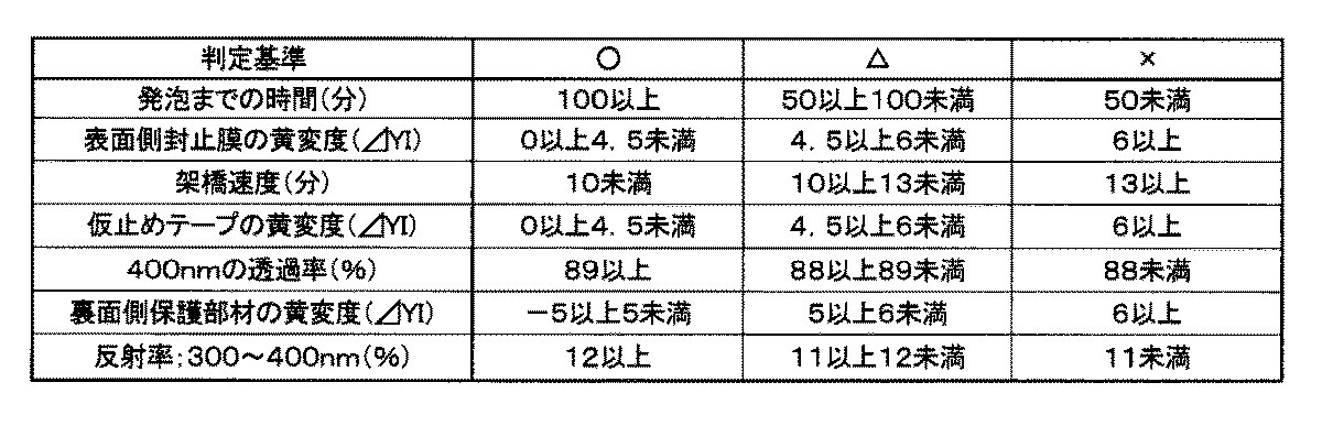
<総合判定>
上記(1)~(7)の評価を表3に示す基準でそれぞれ判定し、合計7つの評価のうち、×を1つでも有するもの、又は△が3つ以上あるものを総合判定×とし、それ以外のものを○とした。
上記(1)~(7)の評価を表3に示す基準でそれぞれ判定し、合計7つの評価のうち、×を1つでも有するもの、又は△が3つ以上あるものを総合判定×とし、それ以外のものを○とした。
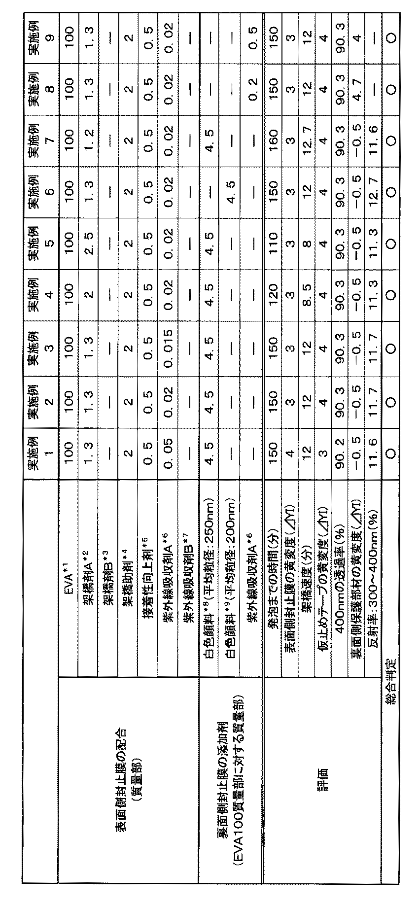
備考)
*1:EVAの酢酸ビニル含有量は26質量%である。
*2:架橋剤A、2,5-ジメチル-2,5-ジ(t-ブチルパーオキシ)ヘキサン(パーヘキサ25B:日本油脂(株)製)
*3:架橋剤B、t-ブチルパーオキシ-2-エチルヘキシルモノカーボネート
*4:架橋助剤、トリアリルイソシアヌレート
*5:接着性向上剤、γ-メタクリロキシプロピルトリメトキシシラン
*6:紫外線吸収剤A、2-ヒドロキシ-4-n-オクトキシベンゾフェノン(スミソーブ130:住友化学(株)製)
*7:紫外線吸収剤B、2,2'-ジヒドロキシ-4,4'-ジメトキシベンゾフェノン
*8:白色顔料、二酸化チタン微粒子(平均粒径:250nm)
*9:白色顔料、二酸化チタン微粒子(平均粒径:200nm)
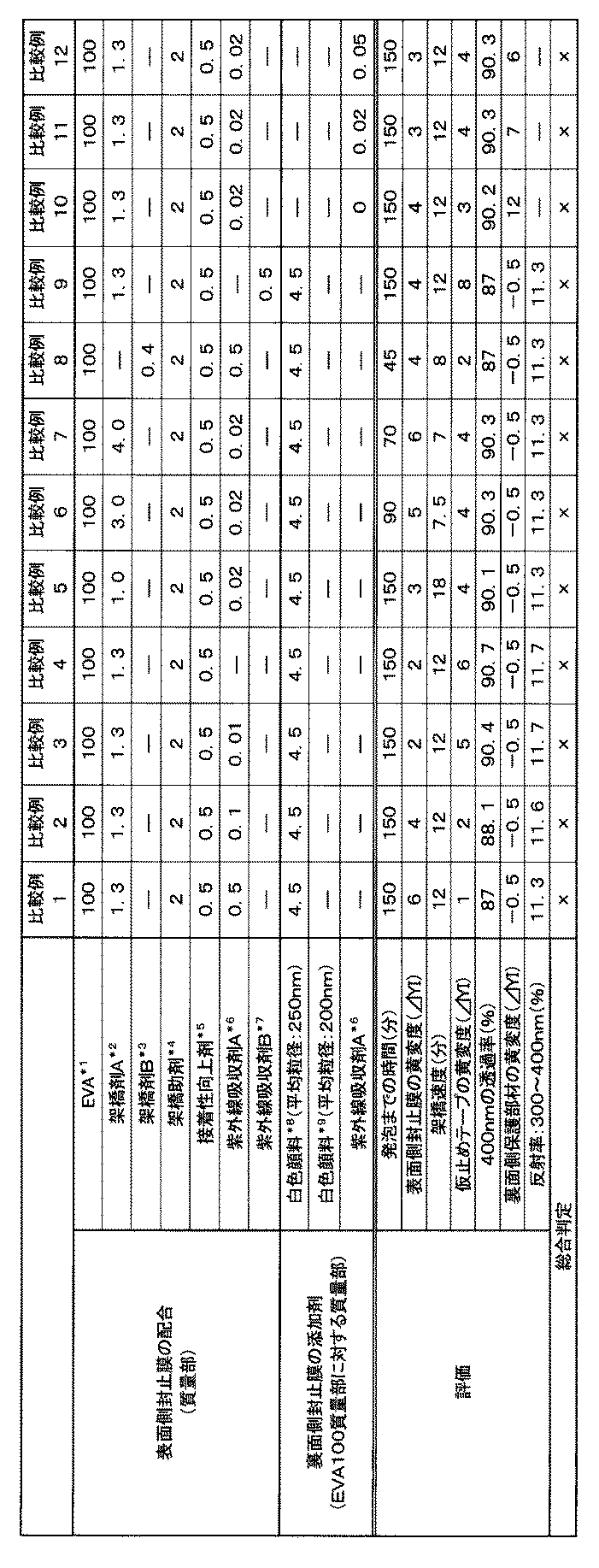
*1~9:表1に従う。
(評価結果)
表1及び表2に示されているように、架橋剤Aの添加量が1.2質量部未満である場合には架橋速度が低下していた。架橋剤Aの添加量が2.5質量部より多い場合には発泡するまでの時間が早く、表面側封止膜が黄変した。紫外線吸収剤Aの添加量が0.015質量部未満の場合には、紫外線透過量が多いため仮止めテープの黄変が生じていた。紫外線吸収剤Aの添加量が0.05質量部より多い場合には、表面側封止膜の黄変が生じていた。また、架橋剤Aと紫外線吸収剤Aの組合せ以外の場合には、発泡又は仮止めテープの黄変の点で評価が低かった。
表1及び表2に示されているように、架橋剤Aの添加量が1.2質量部未満である場合には架橋速度が低下していた。架橋剤Aの添加量が2.5質量部より多い場合には発泡するまでの時間が早く、表面側封止膜が黄変した。紫外線吸収剤Aの添加量が0.015質量部未満の場合には、紫外線透過量が多いため仮止めテープの黄変が生じていた。紫外線吸収剤Aの添加量が0.05質量部より多い場合には、表面側封止膜の黄変が生じていた。また、架橋剤Aと紫外線吸収剤Aの組合せ以外の場合には、発泡又は仮止めテープの黄変の点で評価が低かった。
更に、裏面側封止膜に配合した紫外線吸収剤Aの量が0.2未満である場合には、裏面側保護部材の黄変が生じていた。また、裏面側封止膜に配合した白色顔料の平均粒径が200nmの場合には300~400nmにおける反射率が向上していた。
本発明によれば、表面側封止膜、セル止めテープ及び裏面側保護部材の黄変が防止され、架橋時の発泡が抑制され、架橋速度が良好であるので、外観特性が高く、生産性が良好であり、発電効率の向上した太陽電池を得ることが可能である。
11 表面側透明保護部材
12 裏面側保護部材
13A 表面側封止膜
13B 裏面側封止膜
14 太陽電池用セル
15 接続タブ
16 セル止めテープ
17 導電バー
21 ガラス板(表面側透明保護部材)
22 白色顔料を含むPET(裏面側保護部材)
23A 表面側封止膜
23B 裏面側封止膜
26 PET
27 アルムニウム板
28 黒色遮蔽材
12 裏面側保護部材
13A 表面側封止膜
13B 裏面側封止膜
14 太陽電池用セル
15 接続タブ
16 セル止めテープ
17 導電バー
21 ガラス板(表面側透明保護部材)
22 白色顔料を含むPET(裏面側保護部材)
23A 表面側封止膜
23B 裏面側封止膜
26 PET
27 アルムニウム板
28 黒色遮蔽材
Claims (7)
- 表面側透明保護部材、表面側封止膜、太陽電池用セル、裏面側封止膜及び裏面側保護部材がこの順で積層され、且つ前記太陽電池用セルが所定の位置にセル止めテープで仮止めされた積層体を、架橋一体化させることにより前記太陽電池用セルを封止してなる太陽電池に使用する前記表面側封止膜であって、
エチレン-酢酸ビニル共重合体、架橋剤及び紫外線吸収剤を含み、
前記架橋剤が2,5-ジメチル-2,5-ジ(t-ブチルパーオキシ)ヘキサンであり、前記エチレン-酢酸ビニル共重合体100質量部に対して1.2~2.5質量部含み、
前記紫外線吸収剤が2-ヒドロキシ-4-n-オクトキシベンゾフェノンであり、前記エチレン-酢酸ビニル共重合体100質量部に対して0.015~0.05質量部含むことを特徴とする太陽電池用表面側封止膜。 - 表面側透明保護部材、表面側封止膜、太陽電池用セル、裏面側封止膜及び裏面側保護部材がこの順で積層され、且つ前記太陽電池用セルが所定の位置にセル止めテープで仮止めされた積層体を、架橋一体化させることにより前記太陽電池用セルを封止してなる太陽電池であって、
前記表面側封止膜として、請求項1に記載の太陽電池用表面側封止膜を用いたことを特徴とする太陽電池。 - 光源としてメタルハライドランプを使用し、紫外線を照射強度1000W/m2で24時間照射した場合の、JIS-K-7105(1981)に準拠して測定した前記セル止めテープの黄変度(ΔYI)が4以下であることを特徴とする請求項2に記載の太陽電池。
- 前記セル止めテープが、ポリエチレンテレフタレートフィルムの表面に粘着剤層を有するテープであることを特徴とする請求項2又は3に記載の太陽電池。
- 前記裏面側封止膜が、エチレン-酢酸ビニル共重合体、架橋剤及び着色剤を含むことを特徴とする請求項2~4の何れか1項に記載の太陽電池。
- 前記着色剤が、二酸化チタンであることを特徴とする請求項5に記載の太陽電池。
- 前記裏面側封止膜が、エチレン-酢酸ビニル共重合体、架橋剤及び紫外線吸収剤を含み、
前記紫外線吸収剤が、前記エチレン-酢酸ビニル共重合体100質量部に対して、0.2~0.5質量部含むことを特徴とする請求項2~4の何れか1項に記載の太陽電池。
Applications Claiming Priority (2)
| Application Number | Priority Date | Filing Date | Title |
|---|---|---|---|
| JP2011-131839 | 2011-06-14 | ||
| JP2011131839A JP5788721B2 (ja) | 2011-06-14 | 2011-06-14 | 太陽電池用封止膜及びこれを用いた太陽電池 |
Publications (1)
| Publication Number | Publication Date |
|---|---|
| WO2012173006A1 true WO2012173006A1 (ja) | 2012-12-20 |
Family
ID=47356996
Family Applications (1)
| Application Number | Title | Priority Date | Filing Date |
|---|---|---|---|
| PCT/JP2012/064354 Ceased WO2012173006A1 (ja) | 2011-06-14 | 2012-06-04 | 太陽電池用封止膜及びこれを用いた太陽電池 |
Country Status (2)
| Country | Link |
|---|---|
| JP (1) | JP5788721B2 (ja) |
| WO (1) | WO2012173006A1 (ja) |
Cited By (3)
| Publication number | Priority date | Publication date | Assignee | Title |
|---|---|---|---|---|
| ITBO20130477A1 (it) * | 2013-09-06 | 2015-03-07 | Carlo Dallari | Modulo fotovoltaico per la produzione di energia elettrica da energia solare |
| ITBO20130645A1 (it) * | 2013-11-25 | 2015-05-26 | Carlo Dallari | Modulo fotovoltaico per la produzione di energia elettrica da energia solare |
| FR3071682A1 (fr) * | 2017-09-28 | 2019-03-29 | Commissariat A L'energie Atomique Et Aux Energies Alternatives | Procede de fabrication d'un module photovoltaique avec controle de la distance inter-series de cellules photovoltaiques |
Families Citing this family (3)
| Publication number | Priority date | Publication date | Assignee | Title |
|---|---|---|---|---|
| US10435597B2 (en) | 2013-08-16 | 2019-10-08 | Lg Chem, Ltd. | Seal tape |
| KR101862906B1 (ko) * | 2015-04-29 | 2018-05-30 | 주식회사 엘지화학 | 유기 태양 전지 모듈을 포함하는 휴대용 단말기 |
| JP7882403B1 (ja) * | 2025-08-12 | 2026-06-30 | 大日本印刷株式会社 | 太陽電池モジュールおよび太陽電池アレイ |
Citations (4)
| Publication number | Priority date | Publication date | Assignee | Title |
|---|---|---|---|---|
| JP2003324211A (ja) * | 2002-02-27 | 2003-11-14 | Bridgestone Corp | 太陽電池モジュール及びそのための仮止め用テープ |
| JP2010245391A (ja) * | 2009-04-08 | 2010-10-28 | Bridgestone Corp | 太陽電池モジュールの製造方法 |
| JP2011066179A (ja) * | 2009-09-17 | 2011-03-31 | Sliontec Corp | 太陽電池モジュール用の封止材フィルムおよびその製造方法 |
| JP2011111515A (ja) * | 2009-11-26 | 2011-06-09 | Bridgestone Corp | 太陽電池用封止膜、及び太陽電池 |
-
2011
- 2011-06-14 JP JP2011131839A patent/JP5788721B2/ja not_active Expired - Fee Related
-
2012
- 2012-06-04 WO PCT/JP2012/064354 patent/WO2012173006A1/ja not_active Ceased
Patent Citations (4)
| Publication number | Priority date | Publication date | Assignee | Title |
|---|---|---|---|---|
| JP2003324211A (ja) * | 2002-02-27 | 2003-11-14 | Bridgestone Corp | 太陽電池モジュール及びそのための仮止め用テープ |
| JP2010245391A (ja) * | 2009-04-08 | 2010-10-28 | Bridgestone Corp | 太陽電池モジュールの製造方法 |
| JP2011066179A (ja) * | 2009-09-17 | 2011-03-31 | Sliontec Corp | 太陽電池モジュール用の封止材フィルムおよびその製造方法 |
| JP2011111515A (ja) * | 2009-11-26 | 2011-06-09 | Bridgestone Corp | 太陽電池用封止膜、及び太陽電池 |
Cited By (3)
| Publication number | Priority date | Publication date | Assignee | Title |
|---|---|---|---|---|
| ITBO20130477A1 (it) * | 2013-09-06 | 2015-03-07 | Carlo Dallari | Modulo fotovoltaico per la produzione di energia elettrica da energia solare |
| ITBO20130645A1 (it) * | 2013-11-25 | 2015-05-26 | Carlo Dallari | Modulo fotovoltaico per la produzione di energia elettrica da energia solare |
| FR3071682A1 (fr) * | 2017-09-28 | 2019-03-29 | Commissariat A L'energie Atomique Et Aux Energies Alternatives | Procede de fabrication d'un module photovoltaique avec controle de la distance inter-series de cellules photovoltaiques |
Also Published As
| Publication number | Publication date |
|---|---|
| JP2013004595A (ja) | 2013-01-07 |
| JP5788721B2 (ja) | 2015-10-07 |
Similar Documents
| Publication | Publication Date | Title |
|---|---|---|
| JP4479933B2 (ja) | 太陽電池用封止膜及びこれを用いた太陽電池 | |
| JP5469087B2 (ja) | 太陽電池用封止膜及びこれを用いた太陽電池 | |
| JP2011216804A (ja) | 太陽電池用封止膜、これを用いた太陽電池、及び太陽電池の製造方法 | |
| JP4751792B2 (ja) | 太陽電池封止膜用組成物、太陽電池封止膜及びこれを用いた太陽電池 | |
| JP5788721B2 (ja) | 太陽電池用封止膜及びこれを用いた太陽電池 | |
| US9123836B2 (en) | Solar cell sealing film and solar cell using the same | |
| JP2014207457A (ja) | 太陽電池用封止膜及びこれを用いた太陽電池、並びに太陽電池用封止膜における電気絶縁性の低下を抑制する方法 | |
| WO2011102242A1 (ja) | 太陽電池用封止膜及びこれを用いた太陽電池 | |
| JP5369020B2 (ja) | エチレン−酢酸ビニル共重合体シート並びにこれを用いた太陽電池及び合わせガラス | |
| JP2012004146A (ja) | 太陽電池用封止膜及びこれを用いた太陽電池 | |
| JP2008235882A (ja) | 太陽電池用封止膜及びこれを用いた太陽電池 | |
| JP5567896B2 (ja) | 太陽電池封止膜及びこれを用いた太陽電池 | |
| JP2011111515A (ja) | 太陽電池用封止膜、及び太陽電池 | |
| JP2013089888A (ja) | 太陽電池用封止膜及びこれを用いた太陽電池 | |
| JP4918329B2 (ja) | 太陽電池の選別方法 | |
| JP2014015544A (ja) | エチレン−酢酸ビニル共重合体シート、並びにこれを用いた合わせガラス用中間膜、合わせガラス、太陽電池用封止膜及び太陽電池 | |
| JP2011119559A (ja) | 太陽電池用封止膜及び太陽電池 | |
| JP5788712B2 (ja) | エチレン−極性モノマー共重合体シート、並びにこれを用いた合わせガラス用中間膜、合わせガラス、太陽電池用封止膜及び太陽電池 | |
| JP5755950B2 (ja) | 太陽電池封止膜及びこれを用いた太陽電池 | |
| JP5624898B2 (ja) | 太陽電池用裏面側保護部材一体型封止膜の製造方法、並びにこれを用いた太陽電池及びその製造方法 | |
| JP5604335B2 (ja) | 太陽電池用封止膜及びこれを用いた太陽電池 | |
| JP2012182407A (ja) | 太陽電池用封止膜及びこれを用いた太陽電池 | |
| JP2011152686A (ja) | エチレン−酢酸ビニル共重合体シート、その製造方法、並びにそれを用いた合わせガラス及び太陽電池 | |
| JP2011192694A (ja) | 太陽電池用封止膜及びこれを用いた太陽電池 | |
| JP5869211B2 (ja) | 太陽電池用封止膜及びこれを用いた太陽電池 |
Legal Events
| Date | Code | Title | Description |
|---|---|---|---|
| 121 | Ep: the epo has been informed by wipo that ep was designated in this application |
Ref document number: 12800311 Country of ref document: EP Kind code of ref document: A1 |
|
| NENP | Non-entry into the national phase |
Ref country code: DE |
|
| 122 | Ep: pct application non-entry in european phase |
Ref document number: 12800311 Country of ref document: EP Kind code of ref document: A1 |