WO2012172770A1 - 構造物及びその製造方法 - Google Patents
構造物及びその製造方法 Download PDFInfo
- Publication number
- WO2012172770A1 WO2012172770A1 PCT/JP2012/003780 JP2012003780W WO2012172770A1 WO 2012172770 A1 WO2012172770 A1 WO 2012172770A1 JP 2012003780 W JP2012003780 W JP 2012003780W WO 2012172770 A1 WO2012172770 A1 WO 2012172770A1
- Authority
- WO
- WIPO (PCT)
- Prior art keywords
- opening
- region
- stage
- opening area
- shape
- Prior art date
- Legal status (The legal status is an assumption and is not a legal conclusion. Google has not performed a legal analysis and makes no representation as to the accuracy of the status listed.)
- Ceased
Links
Images

Classifications
-
- B—PERFORMING OPERATIONS; TRANSPORTING
- B32—LAYERED PRODUCTS
- B32B—LAYERED PRODUCTS, i.e. PRODUCTS BUILT-UP OF STRATA OF FLAT OR NON-FLAT, e.g. CELLULAR OR HONEYCOMB, FORM
- B32B3/00—Layered products comprising a layer with external or internal discontinuities or unevennesses, or a layer of non-planar shape; Layered products comprising a layer having particular features of form
- B32B3/10—Layered products comprising a layer with external or internal discontinuities or unevennesses, or a layer of non-planar shape; Layered products comprising a layer having particular features of form characterised by a discontinuous layer, i.e. formed of separate pieces of material
- B32B3/12—Layered products comprising a layer with external or internal discontinuities or unevennesses, or a layer of non-planar shape; Layered products comprising a layer having particular features of form characterised by a discontinuous layer, i.e. formed of separate pieces of material characterised by a layer of regularly- arranged cells, e.g. a honeycomb structure
-
- B—PERFORMING OPERATIONS; TRANSPORTING
- B29—WORKING OF PLASTICS; WORKING OF SUBSTANCES IN A PLASTIC STATE IN GENERAL
- B29C—SHAPING OR JOINING OF PLASTICS; SHAPING OF MATERIAL IN A PLASTIC STATE, NOT OTHERWISE PROVIDED FOR; AFTER-TREATMENT OF THE SHAPED PRODUCTS, e.g. REPAIRING
- B29C64/00—Additive manufacturing, i.e. manufacturing of three-dimensional [3D] objects by additive deposition, additive agglomeration or additive layering, e.g. by 3D printing, stereolithography or selective laser sintering
- B29C64/10—Processes of additive manufacturing
- B29C64/106—Processes of additive manufacturing using only liquids or viscous materials, e.g. depositing a continuous bead of viscous material
- B29C64/124—Processes of additive manufacturing using only liquids or viscous materials, e.g. depositing a continuous bead of viscous material using layers of liquid which are selectively solidified
- B29C64/129—Processes of additive manufacturing using only liquids or viscous materials, e.g. depositing a continuous bead of viscous material using layers of liquid which are selectively solidified characterised by the energy source therefor, e.g. by global irradiation combined with a mask
- B29C64/135—Processes of additive manufacturing using only liquids or viscous materials, e.g. depositing a continuous bead of viscous material using layers of liquid which are selectively solidified characterised by the energy source therefor, e.g. by global irradiation combined with a mask the energy source being concentrated, e.g. scanning lasers or focused light sources
-
- B—PERFORMING OPERATIONS; TRANSPORTING
- B29—WORKING OF PLASTICS; WORKING OF SUBSTANCES IN A PLASTIC STATE IN GENERAL
- B29C—SHAPING OR JOINING OF PLASTICS; SHAPING OF MATERIAL IN A PLASTIC STATE, NOT OTHERWISE PROVIDED FOR; AFTER-TREATMENT OF THE SHAPED PRODUCTS, e.g. REPAIRING
- B29C67/00—Shaping techniques not covered by groups B29C39/00 - B29C65/00, B29C70/00 or B29C73/00
- B29C67/20—Shaping techniques not covered by groups B29C39/00 - B29C65/00, B29C70/00 or B29C73/00 for porous or cellular articles, e.g. of foam plastics, coarse-pored
-
- B—PERFORMING OPERATIONS; TRANSPORTING
- B29—WORKING OF PLASTICS; WORKING OF SUBSTANCES IN A PLASTIC STATE IN GENERAL
- B29D—PRODUCING PARTICULAR ARTICLES FROM PLASTICS OR FROM SUBSTANCES IN A PLASTIC STATE
- B29D99/00—Subject matter not provided for in other groups of this subclass
- B29D99/0089—Producing honeycomb structures
-
- Y—GENERAL TAGGING OF NEW TECHNOLOGICAL DEVELOPMENTS; GENERAL TAGGING OF CROSS-SECTIONAL TECHNOLOGIES SPANNING OVER SEVERAL SECTIONS OF THE IPC; TECHNICAL SUBJECTS COVERED BY FORMER USPC CROSS-REFERENCE ART COLLECTIONS [XRACs] AND DIGESTS
- Y10—TECHNICAL SUBJECTS COVERED BY FORMER USPC
- Y10T—TECHNICAL SUBJECTS COVERED BY FORMER US CLASSIFICATION
- Y10T428/00—Stock material or miscellaneous articles
- Y10T428/24—Structurally defined web or sheet [e.g., overall dimension, etc.]
- Y10T428/24149—Honeycomb-like
-
- Y—GENERAL TAGGING OF NEW TECHNOLOGICAL DEVELOPMENTS; GENERAL TAGGING OF CROSS-SECTIONAL TECHNOLOGIES SPANNING OVER SEVERAL SECTIONS OF THE IPC; TECHNICAL SUBJECTS COVERED BY FORMER USPC CROSS-REFERENCE ART COLLECTIONS [XRACs] AND DIGESTS
- Y10—TECHNICAL SUBJECTS COVERED BY FORMER USPC
- Y10T—TECHNICAL SUBJECTS COVERED BY FORMER US CLASSIFICATION
- Y10T428/00—Stock material or miscellaneous articles
- Y10T428/24—Structurally defined web or sheet [e.g., overall dimension, etc.]
- Y10T428/24273—Structurally defined web or sheet [e.g., overall dimension, etc.] including aperture
Definitions
- This technology relates to a structure and a manufacturing method thereof.
- the optically shaped article described in Patent Document 1 is used as a three-dimensional model of an article to be designed, and a portion corresponding to the flesh portion of the designed article in the three-dimensional model is formed hollow, and the hollow interior is a honeycomb. It is formed by the structure. As a result, variations in strength due to the three-dimensional model are reduced (see, for example, paragraph [0020] of Patent Document 1).
- an object of the present technology is to provide a structure having a new shape and a method for manufacturing the structure.
- a structure according to the present technology includes a wall portion, a first opening region, and a plurality of second opening regions.
- the first opening region has a first opening area and is formed by being surrounded by the wall portion.
- the plurality of second opening regions are provided in the wall portion so as to be regularly aligned, and each has a second opening area smaller than the first opening area.
- a second opening region having an opening area smaller than the opening area of the first opening region is provided on the wall portion surrounding the first opening region, and a structure having a new shape can be provided.
- the structure has a third opening area smaller than the second opening area provided to form the second opening area and to be regularly aligned around the second opening area of the wall portion. You may further comprise the 3rd opening area
- the opening directions of the first opening region and the plurality of second opening regions may be the same.
- the opening directions of the first opening region, the plurality of second opening regions, and the plurality of third opening regions may be the same.
- the shape of the structure may be a self-similar shape. In other words, the shape of the structure itself matches the shape of the wall portion of the structure having a larger size.
- the arrangement and shape of at least the first opening region may be an arrangement and shape of a honeycomb structure. Thereby, the intensity
- a material that is cured by energy of energy rays is supplied to a supply region.
- the selected region is irradiated with the energy beam among all the regions of the material supplied to the supply region. Due to the irradiation of the energy beam, the wall portion is provided on the wall portion so as to be regularly aligned with the first opening area having the first opening area and being surrounded by the wall portion. And a structure having a plurality of second opening regions each having a second opening area smaller than the first opening area is formed.
- a regulating body having a stage and a surface including a linear region along the first direction, and arranged facing the stage so that the linear region of the surface is closest to the stage
- the structure may be formed as follows using a structure forming apparatus including In the material supply step, the material is supplied to a slit region which is a region between the region on the side where the stage is disposed and the linear region.
- the manufacturing method of the structure further includes relative positioning of the regulating body and the stage along a second direction different from the first direction in order to form a cured layer of the material for at least one layer. Moved.
- a structure having a new shape can be provided.
- FIG. 1A and 1B are plan views showing a structure according to a first embodiment of the present technology.
- FIG. 2 is a plan view showing a structure according to the second embodiment of the present technology.
- FIG. 3 is a plan view showing a structure according to the third embodiment of the present technology.
- FIG. 4 is a plan view showing a structure according to the fourth embodiment of the present technology.
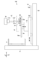
- FIG. 5 is a side view showing a structure forming apparatus according to an embodiment of the present technology.
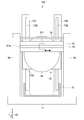
- FIG. 6 is a side view of the structure forming apparatus as viewed in the Z-axis direction.
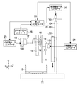
- FIG. 7 is a schematic side view showing the structure forming apparatus and a block diagram showing the configuration of the control system.
- FIG. 8 is an enlarged view of the regulating body.
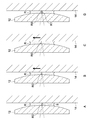
- 9A to 9C are diagrams sequentially illustrating the operation of the structure forming apparatus.
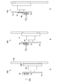
- 10A to 10D are enlarged views showing the area between the regulating body and the stage during the operation.
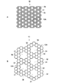
- FIG. 1A is a plan view showing a structure according to the first embodiment of the present technology.
- This structure 10 is a structure having a two-dimensional extension (sheet-like or film-like), and is typically relatively thin in the thickness direction (perpendicular to the plane of FIG. 1A). It is formed in a uniform shape in the thickness direction.
- FIG. 1B is an enlarged view of the structure 10.
- the structure 10 includes a wall portion 36, a plurality of first opening regions 31 formed by being surrounded by the wall portion 36, and a plurality of second opening regions 32 provided in the wall portion 36. Prepare.
- the first opening region 31 and the second opening region 32 are provided so as to be regularly aligned.
- the wall portion 36 is formed by the second opening regions 32 being regularly aligned and gathered.
- the opening directions (inclinations of the opening end faces) of these opening regions 31 and 32 are perpendicular to the paper surface in FIGS. Matching the direction of the openings means that they are substantially aligned, and the direction of the openings is aligned with the direction of the opening "designed" by the designer of the structure. Means that.
- the opening direction of one opening region is shifted by a strictly small angle that the designer does not intend compared to the opening directions of the other plurality of opening regions (for example, the opening end surface has a very small angle from the paper surface). Even if they are misaligned), they are substantially identical.
- the regularity of the alignment of the open regions 31 and 32 varies, but at least one condition is that the pitch of the open regions 31 (and 32) is constant.
- the opening area (second opening area) of the second opening region 32 is smaller than the opening area (first opening area) of the first opening region 31.
- the arrangement and shape of the first opening regions 31 are the arrangement and shape of the honeycomb structure.
- the arrangement and shape of the second opening region 32 are also the arrangement and shape of the honeycomb structure, and the shape of the opening surface of the second opening region 32 is a regular hexagon.
- the shape of the opening surface of the first opening region 31 is a near regular hexagon (specifically, an asterisk (*) shape).
- the shape of the structure 10 is a self-similar shape (fractal shape). That is, a structure that is similar to the unit structure in which a set of unit structures (in this example, the second opening region 32 that is the smallest regular hexagon) is larger than the size of the unit structure. Form.
- a predetermined number of second opening regions 32 are regularly aligned and gathered to form a substantially similar first opening region 31 in the second opening region 32.
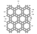
- FIG. 2 is a plan view showing a structure according to the second embodiment of the present technology.
- the structure 110 includes a wall 136, a plurality of first opening regions 137 formed by being surrounded by the wall 136, a plurality of second opening regions 138 provided in the wall 136, And a third opening region 139 forming these second opening regions 138 (walls thereof).
- the shape of the first opening region 137 is substantially a regular hexagon.
- the shape of the structure 110 is a self-similar shape of the structure 10 according to the first embodiment. That is, the structure 10 itself shown in FIG. 1 forms the wall 136 of the structure 110 shown in FIG. In other words, as shown in FIG. 1A, the unit structure is a portion 10A surrounded by a broken line, and a larger opening region (first opening region 137 in FIG. 2) is formed by the unit structure 10A. The resulting structure is this structure 110.
- the opening directions of these opening regions 137, 138 and 139 are perpendicular to the paper surface in FIG.
- the shape of the structure 110 is a self-similar shape, a structure having an infinite number of shapes can be realized.
- the structure 110 shown in FIG. 2 can be used as the wall 136, and a plurality of opening regions surrounded by the wall 136 can be formed.
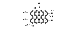
- FIG. 3 is a plan view showing a structure according to the third embodiment of the present technology.
- description of the same structures 10 and 110 according to the embodiment shown in FIGS. 1 and 2 will be simplified or omitted, and different points will be mainly described.
- the wall portion 43 includes a wall portion 43 that forms a first opening region 41, and the wall portion 43 is formed by a plurality of second opening regions 42.
- the difference between the structure 10 (see FIG. 1) and the structure 20 is that the number of the second opening regions 42 for forming one first opening region 41 in the structure 20 is different from that of the structure 10. It is a different point.
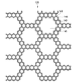
- FIG. 4 is a plan view showing a structure according to the fourth embodiment of the present technology.
- the structure 120 includes a first opening region 141 surrounded by a wall 146, a plurality of second opening regions 142, and a third opening region 143.
- the wall 146 is formed by the structure 20 according to the third embodiment. That is, the shape of the structure 120 is a self-similar shape of the structure 20.
- the aperture ratio of the filter when trying to increase the aperture ratio of the filter, the aperture area increases, the thickness of the portion forming the aperture decreases, and the strength of the filter decreases. On the contrary, when the aperture ratio of the filter is reduced and the wall thickness is increased, the flow rate of the fluid passing through the filter is reduced. That is, the pressure loss increases.
- the aperture ratio increases, so that the surface area of the material per unit mass can be increased by the structure of such a structure.
- the opening region in the wall it is possible to suppress a decrease in the flow rate of the fluid that passes through the filter while obtaining high strength (low pressure loss).
- high strength low pressure loss
- the structure has a honeycomb structure, sufficient strength and rigidity can be obtained.
- the structure according to the present technology may have a coating film formed on the surface thereof by plating, for example.
- the plating may be anything such as metal plating or resin plating.
- plating for example, hydrophobicity (for example, fluorine-based material), hydrophilicity (for example, silica-based or titanium oxide-based material), antifouling property (for example, titanium-based or carbon-based material), heat resistance (for example, Various properties such as nickel-based, chromium-based, and titanium-based materials can be imparted to the structure.
- the structure can be used as a metal fiber reinforced plastic material by performing metal plating on the structure and then resin plating.
- 1 to 4 can be formed by, for example, a modeling apparatus.
- the modeling apparatus irradiates the selected region with energy rays based on the three-dimensional design data of the target structure in the entire region of the supplied material, and partially cures the supplied material. Thereby, the structure of arbitrary shapes can be formed.
- the energy beam is typically light, and particularly ultraviolet light is used. In that case, an ultraviolet curable resin is used as the material.
- the energy rays are not limited to ultraviolet rays, and examples include infrared rays, visible light, electron beams, and ultrasonic waves. Infrared rays, ultrasonic waves, or the like may be used when forming a modeled object with relatively low modeling accuracy.
- Laser irradiation is typically used for light irradiation.
- This structure forming apparatus basically uses the principle of a modeling apparatus.
- the structure formed by the structure forming apparatus can be used not only as a model but also as an actual product.
- FIG. 5 is a side view showing a structure forming apparatus according to an embodiment of the present technology.
- FIG. 6 is a side view of the structure forming apparatus as viewed in the Z-axis direction.
- FIG. 7 is a schematic side view showing the structure forming apparatus and a block diagram showing the configuration of the control system.
- the X, Y, and Z axes are three axes orthogonal to each other.
- the structure forming apparatus 100 includes a base 11, a Y-axis moving mechanism 13 erected in the vertical direction on the base 11, a Z-axis moving mechanism 15 connected to the Y-axis moving mechanism 13, and a Z-axis moving mechanism 15. And a connected stage 14. Further, the structure forming apparatus 100 includes an irradiation unit 17 that irradiates laser light such as ultraviolet rays toward the stage 14 as energy rays. In addition, the structure forming apparatus 100 supplies the regulation body 12 facing the stage 14 and a material such as a photocurable resin that is cured by laser light between the stage 14 and the regulation body 12. Nozzle 16.
- the Y-axis moving mechanism 13 is laid along the Y-axis direction (second direction) on the Y-axis moving motor 131 (see FIG. 7), a support column 134 standing on the base 11, and the support column 134. It has a guide rail 132 and a moving base 133 that is connected to the guide rail 132 and is movable along the guide rail 132 by a Y-axis moving motor 131.
- the Z-axis moving mechanism 15 has a Z-axis moving motor 151 (see FIG. 7) and is configured to be able to move the stage 14 in the Z-axis direction.
- the stage 14 is formed in, for example, a circular shape as shown in FIG. 6, but may be a square or other shapes.
- the stage 14 can be moved along the Y and Z axis directions by the Y axis moving mechanism 13 and the Z axis moving mechanism 15.
- the Z-axis moving mechanism 15 controls the distance between the surface 14a of the stage 14 and a region (a linear region A1 described later) closest to the stage 14 in the surface 12a of the regulating body 12.
- the Y-axis moving mechanism 13 and the Z-axis moving mechanism 15 function as moving mechanisms.
- the regulating body 12 regulates the thickness along the Z-axis direction of the material supplied from the supply nozzle 16 to the surface 14 a of the stage 14.
- FIG. 8 is an enlarged view showing the regulating body 12.
- the regulating body 12 has a part of a cylindrical shape (cylindrical lens shape). That is, the surface 12a of the regulating body 12 facing the stage 14 is a curved surface, and the curved surface is formed as a cylindrical surface.
- the regulation body 12 is formed long along one direction (X-axis direction).
- the restricting body 12 is attached to the support pillar 19 by the attachment tool 21.
- a slit 21a is formed in the fixture 21 along the X-axis direction (first direction), and the laser light from the irradiation unit 17 is incident on the regulating body 12 through the slit 21a.
- the regulating body 12 is made of glass, acrylic, or other transparent material.
- the regulation body 12 may be anything as long as it is a material that transmits energy rays with a predetermined transmittance.
- the surface 12a of the regulating body 12 may be coated with a water-repellent film (for example, fluorine) that increases the contact angle of the material.
- the stage 14 can be arranged by the Z-axis moving mechanism 15 so as to form a slit region S between the stage 14 side and the surface 12 a of the regulating body 12.
- the slit region S is formed when the surface 14a of the stage 14 and the linear region A1 along the X-axis direction, which is the portion closest to the stage 14 of the surface 12a of the regulating body 12, face each other.
- This linear region A1 is a part of the surface 12a of the regulating body 12.
- the width of this linear region A1 in the Y-axis direction is 0.1 to 1 mm. Further, the spot diameter of laser light emitted from the irradiation unit 17 described later is 1 to 100 ⁇ m. However, the width and the spot diameter of the linear region A1 can be appropriately changed depending on the size of the restricting body 12, the size of the modeled object (structure), the modeling accuracy, and the like, and can take values other than those ranges. .
- the supply nozzle 16 has a long shape along the X axis.
- the supply nozzle 16 is disposed above the restriction body 12 and is attached to the support column 19 via a support member, for example, by a member (not shown).
- a nozzle having a plurality of holes (not shown) for discharging the photocurable material R (see FIG. 8) along its longitudinal direction is used.
- a slit coat type nozzle having a slit provided along the longitudinal direction thereof may be used as the supply nozzle 16.
- the supply nozzle 16 is connected to, for example, a pump, a pipe, an opening / closing valve (not shown) for introducing the photocurable material R into the supply nozzle 16.
- the irradiation unit 17 includes a laser light source 171 and an objective lens 172 that narrows the beam spot of the laser light emitted from the laser light source 171.
- the laser light source 171 and the objective lens 172 are integrally held by a holder (not shown).
- the objective lens 172 focuses on the photocurable material in the slit region S or a region in the vicinity including the slit region S via the regulating body 12. That is, the objective lens 172 is disposed at a position on the optical axis such that the focal point of the laser light matches at least the photocurable material R in the slit region S.
- an ultraviolet curable resin is used as the photocurable material R.
- the moving mechanism includes an X-axis moving mechanism (scanning mechanism) 18 equipped with an X-axis moving motor 181 (see FIG. 7) that integrally moves the irradiation unit 17 along the X-axis direction.
- the irradiation unit 17 can scan the laser light emitted from the laser light source 18 along the X-axis direction by the X-axis moving mechanism 18.
- a polygon scanner or a galvano scanner may be used as the X-axis moving mechanism.
- the slit 21a of the fixture 21 is formed long along the X-axis direction. Therefore, the X-axis moving mechanism 18 can cause the laser light to enter the restricting body 12 through the slit 21a when scanning the laser light.
- the Z-axis moving mechanism 15, the Y-axis moving mechanism 13, and the X-axis moving mechanism 18 can be realized by, for example, a ball screw driving mechanism, a rack and pinion driving mechanism, or a belt driving mechanism.
- the waste liquid tank 5 is provided on the base 11 and below the stage 14.
- the waste liquid tank 5 is configured to store excess photocurable material and the like discharged from the supply nozzle 16 and flowing down through the stage 14.
- the structure forming apparatus 100 includes a Z-axis movement motor controller 28 that controls driving of the Z-axis movement motor 151, a Y-axis movement motor controller 27 that controls driving of the Y-axis movement motor 131, and an X-axis.
- An X-axis movement motor controller 25 that controls driving of the movement motor 181 is provided.
- the structure forming apparatus 100 also includes a laser power controller 26 that controls the power of the laser light emitted from the laser light source 171. The operations of these controllers 25 to 28 are comprehensively controlled by the host computer 50.
- the structure forming apparatus 100 also includes a controller for driving a pump and an on-off valve connected to the supply nozzle 16.
- the host computer 50 includes a CPU (Central Processing Unit), a RAM (Random Access Memory), a ROM (Read Only Memory), and the like. Instead of the CPU, a PLD (Programmable Logic Device) such as FPGA (Field Programmable Gate Array) or ASIC (Application Specific Integrated Circuit) may be used. Each of the controllers 25 to 28 includes such hardware or is configured by software.
- CPU Central Processing Unit
- RAM Random Access Memory
- ROM Read Only Memory
- PLD Programmable Logic Device
- FPGA Field Programmable Gate Array
- ASIC Application Specific Integrated Circuit
- the host computer 50 and the controllers 25 to 28 are connected to each other by wire, but at least one of these controllers may be connected to a control system in the structure forming apparatus 100 by radio.
- FIGS. 10A to 10D are enlarged views showing a region between the regulating body 12 and the stage 14 during the operation.
- FIG. 9A shows a stationary state of the structure forming apparatus 100, and shows a state where the moving base 133 is in the initial position.
- the thickness of one layer of the cured layer that is the photocurable material R is set via the host computer 50. For example, when the stage 14 comes into contact with the linear region A1 that is the portion closest to the stage 14 of the regulating body 12 by driving the Z-axis moving mechanism 15 according to the control of the Z-axis moving motor controller 28 (FIG. 9A) is set as the origin in the Z-axis direction.
- the position of the stage 14 in the Y-axis direction at the time of setting the origin can be set as appropriate.
- the stage 14 is separated from the regulating body 12 by a preset thickness of one layer of the photocurable material R.
- the stage 14 is moved to the modeling start position which is a predetermined position as shown in FIG. 9B by the Y-axis moving mechanism 13.
- This modeling start position is a position in the direction along the Y axis of the stage 14 such that a slit region S between the stage 14 and the linear region A1 of the regulating body 12 can be formed. If the modeling start position is the position of the stage 14 where the slit region S can be formed, the setting can be appropriately changed depending on the size of the structure to be formed in the Y-axis direction.
- the photocurable material R When the stage 14 is positioned at the modeling start position, the photocurable material R is discharged from the supply nozzle 16 and flows down between the regulating body 12 and the stage 14 by its own weight. Thereby, at least the slit region S is filled with the photocurable material R.
- the photocurable material R is held between the regulation body 12 and the stage 14 by surface tension. That is, the regulation body 12 regulates the liquid level of the photocurable material R in a one-dimensional area along the X-axis direction by the linear area A1.
- FIG. 8 shows an enlarged view of the slit region S and its surroundings at this time. From such a state, irradiation of the laser light photocurable material R, that is, exposure is started.
- the irradiation unit 17 emits laser light. Laser light generated from the laser light source 171 passes through the objective lens 172 and the regulating body 12 and enters the photocurable material R in the slit region S. The irradiation unit 17 moves in the direction along the X axis under the control of the X axis moving motor controller 25, and based on the data for one column in the X axis direction in one layer of the modeling target, the laser power controller In accordance with the control 26, the photocurable material R is selectively exposed (see FIG. 10A).
- the laser power controller 26 generates a laser power modulation signal in accordance with the data for the one column of the structure, and sends the laser power modulation signal to the laser light source 171 so that the X-axis direction in one layer can be obtained.
- One row of the photo-curable material R is selectively exposed and cured. At least the photocurable material R in the slit region S is exposed. During exposure by laser light irradiation, the stage 14 is stopped.
- the thickness of one layer of the structure is 1 to 100 ⁇ m, but is not limited to this range and can be set as appropriate.
- one row of the hardened layer R0 is formed.
- the laser beam irradiation operation stops, and the stage 14 moves along the Y-axis by the movement of the moving base 133 by the Y-axis moving mechanism 13. It moves by a predetermined pitch to the rear side (upper side in FIG. 10B) in the above direction.
- FIGS. 10B and 10C when the cured product R0 moves together with the stage 14, a shearing force is generated between the regulating body 12 and the cured product R0, and the regulating body 12 and the cured product R0 are separated from each other. It is peeled off. Since the hydrophobic film is formed on the surface of the regulating body 12 as described above, this peeling is further easily performed.
- the structure forming apparatus 100 repeats the scan irradiation of the laser beam along the X-axis direction and the step feed along the Y-axis direction of the stage 14 as described above.
- a selectively cured layer of the photo-curable material R for 1 minute, that is, a cured layer R ′ for one layer is formed.
- exposure processing for one layer is performed in the manner of so-called raster scanning.
- the pitch of the intermittent movement of the stage 14 in the direction along the Y-axis depends on the spot diameter of the laser beam, that is, on the resolution when forming the structure, but the pitch of this movement is It can be set as appropriate.
- the stage 14 moves further away from the regulating body 12 in the Z-axis direction. Then, by repeating the operations described so far, the hardened layer R ′ is laminated, and a structure having an arbitrary shape is formed.
- the stage 14 moves along the Y-axis direction.
- the linear region A1 of the restricting body 12 moves so as to be relatively separated from the stage 14 along the Z-axis direction.
- a shearing force is generated as described above, and the cured material (such as R0 and R1 shown in FIGS. 10B and 10D) can be removed cleanly from the regulating body 12.
- the shape of the surface of the regulation body 12 is a cylindrical surface, and the liquid level of the photocurable material is regulated by the linear region A1. Therefore, even if a shrinkage force when the photocurable material R is cured is applied to the restricting body 12, the restricting body 12 is unlikely to be deformed or distorted, and is restricted by the viscosity of the photocurable material R before exposure. The deformation of the body 12 can also be prevented. Thereby, the flatness of a hardened layer can be raised and the thickness can be controlled with high precision. As a result, the structure as shown in FIGS. 1 to 4 can be formed in a small size.
- the structure forming apparatus 100 has a diameter of an opening surface of the second opening region (in this example, a distance from a vertex in the second opening region to a vertex facing it). ) Can be formed as a structure having a small size of 5 to 10 ⁇ m. Of course, a structure having a larger size can be formed by a conventional structure forming apparatus.
- the structure is peeled off from the regulating body 12 for each step feed in the direction along the Y axis of the stage 14 during the exposure process. That is, the time required for forming the structure can be shortened because the time zone for the exposure process and the peeling process for one layer overlap.
- liquid level of the photocurable material is regulated by the linear region A1
- a structure can be formed with an accurate layer thickness even when a resin material having a high viscosity is used.
- the range of choices expands.
- peeling of the regulating body 12 from the stage 14 side occurs intermittently by a minute amount (every step feed along the Y-axis direction). Therefore, the peeling force is weak and damage to the cured product can be prevented. That is, the cured product is easily peeled off from the regulation body 12. Moreover, since the peeling force is so weak, the cured product does not peel off from the stage 14.
- the structure shown in FIGS. 1 to 4 can be formed with high accuracy at a practical speed and cost.
- the opening directions of the first opening region and the second opening region (and the third opening region) coincided.
- these opening directions may be different.
- the opening direction of the first opening region 31 shown in FIG. 1A is perpendicular to the paper surface
- the opening direction of the second opening region is parallel to the paper surface, that is, orthogonal to the thickness direction of the structure 10. It may be a direction.
- the second opening region shown in FIG. 3 and the third opening region shown in FIGS. 2 and 4 may be in a direction orthogonal to the thickness direction of the structure.
- the structures 10, 110, 20, 120 according to the above embodiments were self-similar. However, it is not limited to self-similarity. As long as the structure is provided with a second opening region that is regularly aligned with the wall portion forming the first opening region and has an opening area smaller than the opening area of the first opening region, It may be a shaped structure.
- the shape of the first and second opening regions may be a circle, an ellipse, or a rectangle having three or more corners.
- the shapes of the first and second opening regions may be different.
- the structure is a self-similar shape, the same can be said for the shape of the opening region that continues from the third, fourth,...
- the shapes of the plurality of first opening regions are the same, but at least one of these is different from the other. It may be formed in a shape.
- the structure according to each of the above embodiments has a honeycomb structure, the structure is not limited to the honeycomb structure.
- the regulation body of the structure forming apparatus is a part of a cylindrical shape, it may have the entire shape of a cylindrical shape.
- the regulation body may be a solid type made of a material transparent to the energy rays, or may be a hollow type.
- the shape of the surface of the regulating body may not be a cylindrical surface, but may be a curved surface such as an elliptical surface or a hyperboloid.
- the surface thereof may not be a curved surface but may be a flat surface having a narrow width (about 2 to 5 times the laser spot diameter) in the Y-axis direction.
- the regulating body 12 is stationary and the stage 14 is moved in the Z-axis direction during modeling. It is not restricted to such a system, A regulation body may move in the Z-axis direction, the stage 14 may stand still, or both of them may move.
- the stage 14 is moved in the vertical direction in order to form a hardened layer for one layer of the structure.
- the regulating body and the stage may move relative to each other in the horizontal direction, or include a component in the vertical direction, which is different from the vertical direction, that is, You may move relatively in an oblique direction.
- the direction in which the linear region A1 of the restricting body 12 extends (the first direction) as the direction in which the restricting body 12 and the stage 14 move relatively.
- the second direction only needs to be different from the first direction, and may be oblique with respect to the first direction.
- the regulating body 12 and the stage 14 are stationary in the X-axis direction, and the irradiation unit 17 is moved along the X-axis direction.
- the irradiation unit is stationary and the regulating body and the stage are integrated with the X.
- the axis may be moved.
- the structure forming apparatus formed a structure by laminating two or more hardened layers.
- the structure forming apparatus may form a thin structure as shown in FIGS. 1 to 4 by forming at least one hardened layer.
- the structure forming apparatus is taken as an example of the apparatus for forming the structure.
- the structure can be formed also by injection molding.
- the opening area is on the order of ⁇ m, the structure is too small, which makes it difficult for injection molding.
- the present technology can be configured as follows. (1) a wall, A first opening area having a first opening area and surrounded by the wall; A plurality of second opening regions provided on the wall portion so as to be regularly aligned and each having a second opening area smaller than the first opening area. (2) The structure according to (1), The second opening area is formed on the wall so as to be regularly arranged around one second opening area of the plurality of second opening areas, and the second opening area A structure further comprising a plurality of third opening regions each having a smaller third opening area. (3) The structure according to (1), Structures in which the opening directions of the first opening region and the plurality of second opening regions are the same.
- the structure according to (2) Structures in which the first opening region, the plurality of second opening regions, and the plurality of third opening regions have the same opening direction.
- the structure according to any one of (1) to (4), The shape of the structure is a self-similar shape.
- the structure according to any one of (1) to (5), At least the arrangement and shape of the first opening regions are an arrangement and shape of a honeycomb structure.
- the manufacturing method of the structure further includes relative positioning of the regulating body and the stage along a second direction different from the first direction in order to form a cured layer of the material for at least one layer.
Landscapes
- Engineering & Computer Science (AREA)
- Mechanical Engineering (AREA)
- Physics & Mathematics (AREA)
- Optics & Photonics (AREA)
- Chemical & Material Sciences (AREA)
- Materials Engineering (AREA)
- Manufacturing & Machinery (AREA)
- Filtering Materials (AREA)
Priority Applications (3)
| Application Number | Priority Date | Filing Date | Title |
|---|---|---|---|
| US14/124,530 US20140113105A1 (en) | 2011-06-17 | 2012-06-11 | Structure and method of producing the same |
| CN201280028384.7A CN103608166B (zh) | 2011-06-17 | 2012-06-11 | 结构体及其生产方法 |
| EP12799786.4A EP2722159A4 (en) | 2011-06-17 | 2012-06-11 | STRUCTURE AND MANUFACTURING METHOD THEREFOR |
Applications Claiming Priority (2)
| Application Number | Priority Date | Filing Date | Title |
|---|---|---|---|
| JP2011134937A JP5803316B2 (ja) | 2011-06-17 | 2011-06-17 | 構造物の製造方法 |
| JP2011-134937 | 2011-06-17 |
Publications (1)
| Publication Number | Publication Date |
|---|---|
| WO2012172770A1 true WO2012172770A1 (ja) | 2012-12-20 |
Family
ID=47356777
Family Applications (1)
| Application Number | Title | Priority Date | Filing Date |
|---|---|---|---|
| PCT/JP2012/003780 Ceased WO2012172770A1 (ja) | 2011-06-17 | 2012-06-11 | 構造物及びその製造方法 |
Country Status (5)
| Country | Link |
|---|---|
| US (1) | US20140113105A1 (enExample) |
| EP (1) | EP2722159A4 (enExample) |
| JP (1) | JP5803316B2 (enExample) |
| CN (1) | CN103608166B (enExample) |
| WO (1) | WO2012172770A1 (enExample) |
Families Citing this family (9)
| Publication number | Priority date | Publication date | Assignee | Title |
|---|---|---|---|---|
| DE112014001464T5 (de) * | 2013-03-15 | 2016-02-18 | Pyrotek Incorporated | Keramikfilter |
| TWI609769B (zh) | 2014-06-03 | 2018-01-01 | 三緯國際立體列印科技股份有限公司 | 立體結構與立體列印方法 |
| EP3017932A1 (en) * | 2014-10-07 | 2016-05-11 | Kapsch TrafficCom AG | Method of producing a core for a construction element and 3D-printer therefore |
| FR3027554B1 (fr) * | 2014-10-27 | 2020-02-07 | Centre National De La Recherche Scientifique | Procede d'impression en trois dimensions |
| MX2018000874A (es) * | 2015-07-22 | 2018-08-15 | Ask Chemicals Lp | Filtro de ceramica y metodo para formar el filtro. |
| US11230053B2 (en) | 2016-01-21 | 2022-01-25 | 3M Innovative Properties Company | Additive processing of fluoropolymers |
| US20200164572A1 (en) * | 2017-06-30 | 2020-05-28 | 3M Innovative Properties Company | Three-dimensional article and method of making a three-dimensional article |
| DE102018206120A1 (de) * | 2018-04-20 | 2019-10-24 | Faurecia Innenraum Systeme Gmbh | Verbundteil, insbesondere Innenverkleidungsteil, und Verfahren zu dessen Herstellung |
| JP2021130227A (ja) * | 2020-02-19 | 2021-09-09 | 株式会社リコー | フィルタおよびその製造方法、水の浄化装置、発電装置、並びに発電システム |
Citations (4)
| Publication number | Priority date | Publication date | Assignee | Title |
|---|---|---|---|---|
| JPH06509530A (ja) * | 1992-06-02 | 1994-10-27 | アルカテル | 立体リソグラフィーを使用するフラクタル物体の製造方法、及び、かかる方法で得られるフラクタル物体 |
| JP2002347125A (ja) | 2001-05-24 | 2002-12-04 | Nakakin:Kk | 光造形物 |
| JP2002349246A (ja) * | 2001-05-25 | 2002-12-04 | Nippon Steel Chem Co Ltd | 排ガスの微粒子除去装置及び方法 |
| WO2005027611A1 (ja) * | 2003-09-08 | 2005-03-24 | Juridical Foundation Osaka Industrial Promotion Organization | フラクタル構造体、フラクタル構造集合体およびそれらの製造方法ならびに用途 |
Family Cites Families (9)
| Publication number | Priority date | Publication date | Assignee | Title |
|---|---|---|---|---|
| US4416676A (en) * | 1982-02-22 | 1983-11-22 | Corning Glass Works | Honeycomb filter and method of making it |
| JP2003200398A (ja) * | 2001-10-30 | 2003-07-15 | Sony Corp | 多重化階層構造体およびその製造方法ならびに機能材料およびその製造方法ならびに電子装置およびその製造方法ならびにらせん構造体 |
| WO2004024295A1 (ja) * | 2002-09-13 | 2004-03-25 | Ibiden Co., Ltd. | ハニカム構造体 |
| US20040121120A1 (en) * | 2002-12-20 | 2004-06-24 | The Procter & Gamble Company | Apparatus for making a polymeric web exhibiting a soft and silky tactile impression |
| ES2546329T3 (es) * | 2003-07-24 | 2015-09-22 | Tecomet Inc. | Espumas no aleatorias ensambladas |
| JP5040152B2 (ja) * | 2006-04-12 | 2012-10-03 | 東洋製罐株式会社 | 構造体、構造体の形成方法及び構造体形成装置 |
| US7785520B2 (en) * | 2006-12-15 | 2010-08-31 | E.I. Du Pont De Nemours And Company | Processes for making shaped honeycomb and honeycombs made thereby |
| US8828517B2 (en) * | 2009-03-23 | 2014-09-09 | Solexel, Inc. | Structure and method for improving solar cell efficiency and mechanical strength |
| JP2011098484A (ja) * | 2009-11-05 | 2011-05-19 | Sony Corp | 3次元光造形装置、3次元光造形方法及び造形物 |
-
2011
- 2011-06-17 JP JP2011134937A patent/JP5803316B2/ja not_active Expired - Fee Related
-
2012
- 2012-06-11 WO PCT/JP2012/003780 patent/WO2012172770A1/ja not_active Ceased
- 2012-06-11 CN CN201280028384.7A patent/CN103608166B/zh not_active Expired - Fee Related
- 2012-06-11 EP EP12799786.4A patent/EP2722159A4/en not_active Withdrawn
- 2012-06-11 US US14/124,530 patent/US20140113105A1/en not_active Abandoned
Patent Citations (4)
| Publication number | Priority date | Publication date | Assignee | Title |
|---|---|---|---|---|
| JPH06509530A (ja) * | 1992-06-02 | 1994-10-27 | アルカテル | 立体リソグラフィーを使用するフラクタル物体の製造方法、及び、かかる方法で得られるフラクタル物体 |
| JP2002347125A (ja) | 2001-05-24 | 2002-12-04 | Nakakin:Kk | 光造形物 |
| JP2002349246A (ja) * | 2001-05-25 | 2002-12-04 | Nippon Steel Chem Co Ltd | 排ガスの微粒子除去装置及び方法 |
| WO2005027611A1 (ja) * | 2003-09-08 | 2005-03-24 | Juridical Foundation Osaka Industrial Promotion Organization | フラクタル構造体、フラクタル構造集合体およびそれらの製造方法ならびに用途 |
Non-Patent Citations (1)
| Title |
|---|
| See also references of EP2722159A4 |
Also Published As
| Publication number | Publication date |
|---|---|
| JP2013000998A (ja) | 2013-01-07 |
| CN103608166A (zh) | 2014-02-26 |
| US20140113105A1 (en) | 2014-04-24 |
| EP2722159A4 (en) | 2015-02-18 |
| EP2722159A1 (en) | 2014-04-23 |
| CN103608166B (zh) | 2016-07-06 |
| JP5803316B2 (ja) | 2015-11-04 |
Similar Documents
| Publication | Publication Date | Title |
|---|---|---|
| JP5803316B2 (ja) | 構造物の製造方法 | |
| JP5884321B2 (ja) | 構造物の製造方法 | |
| JP2012240216A (ja) | 3次元造形装置、造形物及び造形物の製造方法 | |
| ES2754073T3 (es) | Dispositivo y procedimiento para generar estructuras tridimensionales | |
| JP2012040757A (ja) | 3次元造形装置、造形物及び造形物の製造方法 | |
| EP3083213B1 (en) | Method for printing a three-dimensional light guiding structure by curing droplets of a printing material by light irradiation | |
| KR101704553B1 (ko) | 조형광원어레이 및 폴리곤미러를 구비하는 입체조형장비의 헤드장치 및 이를 이용하는 조형평면 스캐닝 방법 | |
| JP2006068762A (ja) | レーザー加工方法およびレーザー加工装置 | |
| US11097482B2 (en) | System and method for forming nano-structures on substrates to provide predetermined physical characteristics to the substrates | |
| JP6020672B2 (ja) | 3次元造形装置及び造形物の製造方法 | |
| JP6344447B2 (ja) | 3次元造形装置及び造形物の製造方法 | |
| JP6451420B2 (ja) | 接合構造体の製造方法 | |
| JP6844217B2 (ja) | 情報処理装置、造形装置、情報処理方法、およびプログラム | |
| JP6841017B2 (ja) | 造形装置および造形物の製造方法 | |
| JP2015085626A (ja) | 成形体の製造方法 | |
| JP6862795B2 (ja) | 造形装置及び造形物の製造方法 | |
| KR101149069B1 (ko) | 표면장력을 이용한 무용기 성형시스템을 구비한 광조형 장치 | |
| JP2018140643A (ja) | 3次元造形装置及び造形物の製造方法 | |
| WO2025141307A1 (en) | Multi-material 3d micro-printing in laminar flow | |
| Choi et al. | Curing characteristics of three-dimensional microstructures using dynamic pattern projection | |
| HK1250154A1 (zh) | 用於本体或表面的激光辅助加工的装置和方法 | |
| CN120268299A (zh) | 一种非球形微纳气泡图案化的控制系统及方法 |
Legal Events
| Date | Code | Title | Description |
|---|---|---|---|
| 121 | Ep: the epo has been informed by wipo that ep was designated in this application |
Ref document number: 12799786 Country of ref document: EP Kind code of ref document: A1 |
|
| WWE | Wipo information: entry into national phase |
Ref document number: 2012799786 Country of ref document: EP |
|
| WWE | Wipo information: entry into national phase |
Ref document number: 14124530 Country of ref document: US |
|
| NENP | Non-entry into the national phase |
Ref country code: DE |