WO2012172767A1 - 分光感度測定装置、および、分光感度測定方法 - Google Patents
分光感度測定装置、および、分光感度測定方法 Download PDFInfo
- Publication number
- WO2012172767A1 WO2012172767A1 PCT/JP2012/003766 JP2012003766W WO2012172767A1 WO 2012172767 A1 WO2012172767 A1 WO 2012172767A1 JP 2012003766 W JP2012003766 W JP 2012003766W WO 2012172767 A1 WO2012172767 A1 WO 2012172767A1
- Authority
- WO
- WIPO (PCT)
- Prior art keywords
- spectral sensitivity
- short
- circuit current
- light
- measured
- Prior art date
- Legal status (The legal status is an assumption and is not a legal conclusion. Google has not performed a legal analysis and makes no representation as to the accuracy of the status listed.)
- Ceased
Links
Images



Classifications
-
- H—ELECTRICITY
- H02—GENERATION; CONVERSION OR DISTRIBUTION OF ELECTRIC POWER
- H02S—GENERATION OF ELECTRIC POWER BY CONVERSION OF INFRARED RADIATION, VISIBLE LIGHT OR ULTRAVIOLET LIGHT, e.g. USING PHOTOVOLTAIC [PV] MODULES
- H02S50/00—Monitoring or testing of PV systems, e.g. load balancing or fault identification
- H02S50/10—Testing of PV devices, e.g. of PV modules or single PV cells
-
- Y—GENERAL TAGGING OF NEW TECHNOLOGICAL DEVELOPMENTS; GENERAL TAGGING OF CROSS-SECTIONAL TECHNOLOGIES SPANNING OVER SEVERAL SECTIONS OF THE IPC; TECHNICAL SUBJECTS COVERED BY FORMER USPC CROSS-REFERENCE ART COLLECTIONS [XRACs] AND DIGESTS
- Y02—TECHNOLOGIES OR APPLICATIONS FOR MITIGATION OR ADAPTATION AGAINST CLIMATE CHANGE
- Y02E—REDUCTION OF GREENHOUSE GAS [GHG] EMISSIONS, RELATED TO ENERGY GENERATION, TRANSMISSION OR DISTRIBUTION
- Y02E10/00—Energy generation through renewable energy sources
- Y02E10/50—Photovoltaic [PV] energy
Definitions
- the present invention relates to an apparatus and a method for determining the spectral sensitivity of a solar cell.
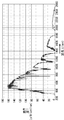
- FIG. 2 shows the spectral irradiance E ( ⁇ ) of the reference sunlight, which is shown in IEC60904.
- FIG. 3 shows an example of the spectral irradiance L ( ⁇ ) of the solar simulator.
- the horizontal axis indicates the wavelength expressed in nm
- the vertical axis indicates the illuminance expressed in ⁇ W / cm 2 / nm
- the horizontal axis indicates the wavelength expressed in nm
- the vertical axis indicates the illuminance expressed in ⁇ W / cm 2 / nm.
- the measurer uses the returned sample as the company's reference cell for light adjustment of the solar simulator. That is, the measurer irradiates the reference cell with the irradiation light of the solar simulator, and adjusts the light amount of the solar simulator so that the short circuit current I becomes the measurement value A. And the characteristic of the solar cell (of the product to be inspected) to be actually measured is measured. Although it is difficult to accurately reproduce the spectrum of the reference sunlight as described above, this is a technique for adjusting the solar simulators of various companies to the extent possible.
- the measurer when the solar simulator is calibrated using the reference cell, the measurer creates a sample in advance and sends it to a public institution such as the National Institute of Advanced Industrial Science and Technology. Need to receive a measured short circuit current measurement and sample. This is time consuming, time consuming and expensive.
- the solar simulator need not be calibrated only once, but each time the spectral sensitivity of the solar cell to be measured changes, a new reference cell must be created and calibrated again. Therefore, the time and cost required for calibration of the solar simulator are enormous.
- Non-Patent Document 1 when adjusting the light amount of the solar simulator, in order to price the short-circuit current due to the light of the standard test condition of the reference cell, that is, as a method of calculating the short-circuit current ISTC due to the light of the standard test condition of the solar cell, A method has been proposed (see Non-Patent Document 1).
- S (I) ⁇ S (I, ⁇ ) obtained from the spectral sensitivity (differential spectral response) S (I, ⁇ ) of the solar cell and the spectral irradiance E AM1.5 ⁇ ( ⁇ ) of the standard test conditions of the reference cell ⁇ ) ⁇ ⁇ E AM1.5 ⁇ ( ⁇ ) d ⁇ / ⁇ E AM1.5 ⁇ ( ⁇ ′) d ⁇ ′ ⁇ is used, and I STC satisfying the following formula A is the light of the standard test condition of the solar cell. Due to the short circuit current.
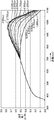
- FIG. 4 in the solar cell, as the irradiation intensity applied to the solar cell increases and the short-circuit current increases, the spectral sensitivity of the long wavelength increases.
- the graph indicated by reference symbol F0 is a graph schematically showing FIG. 4, and the graphs indicated by reference symbols F1, F2, F3, etc. are graphs showing the spectral sensitivities for each irradiation intensity in FIG.
- the horizontal axis indicates the wavelength expressed in nm
- the vertical axis indicates the conversion efficiency expressed in A / W.
- the graph indicating the relationship between the irradiation intensity and the short circuit current is a straight line.
- the graph showing the relationship between the irradiation intensity and the short-circuit current is a curve graph as indicated by the reference symbol Fa. become.
- the sensitivity on the long wavelength side increases and the value of ⁇ I / ⁇ E increases.
- the spectral sensitivity S (I i , ⁇ ) is measured by sequentially applying different monochromatic lights (actually, having a narrow wavelength band of several nanometers) while irradiating the bias light whose short-circuit current I i is measured. Light of a wavelength), and the current from the solar cell is sequentially obtained.
- the spectral sensitivity S (I i , ⁇ ) needs to be obtained in a predetermined wide wavelength range according to the characteristics of the solar cell. For example, CIS type solar cells have photosensitivity in the range of 300 nm to 1300 nm.
- the bias light is stable. Need to be.
- the present invention has been made in view of the above circumstances, and even if the short-circuit current fluctuates without the bias light being stabilized while measuring the spectral sensitivity, the spectral sensitivity at the desired short-circuit current I i is
- An object of the present invention is to provide a spectral sensitivity measuring apparatus and method capable of obtaining S (I i , ⁇ ).
- the spectral sensitivity measuring apparatus includes a light source unit capable of individually irradiating a solar cell to be measured with a plurality of irradiation lights having different light amounts superimposed on light of a narrow wavelength band,
- the measurement unit that measures the short-circuit current and spectral sensitivity of the solar cell when receiving any one of the irradiation lights, and the measurement when sequentially irradiating the plurality of irradiation lights individually
- the spectral sensitivity of the predetermined narrow wavelength band when the desired short-circuit current is measured is calculated based on the respective short-circuit currents measured in the unit and the spectral sensitivity when the short-circuit current is measured.
- a spectral sensitivity calculation unit Therefore, such a spectral sensitivity measuring apparatus can obtain the spectral sensitivity at a desired short-circuit current even if the short-circuit current fluctuates because the irradiation light is not stabilized while measuring the spectral sensitivity.
- the spectral sensitivity measuring apparatus obtains the spectral sensitivity S (I i , ⁇ ) used when calculating the above (formula A) in consideration of the temporal variation of the bias light during the spectral sensitivity measurement. Is. That is, even if the bias light is not actually stable, the spectral sensitivity S (I i , ⁇ ) measured when the bias light is stable can be obtained.
- FIG. 1 is a block diagram showing the configuration of the spectral sensitivity measuring apparatus 100.
- This spectral sensitivity measuring apparatus 100 irradiates monochromatic light (actually, light having a wavelength having a narrow wavelength band of several nm) while irradiating with bias light, and sequentially obtains the current from the solar cell 11. Is used to calculate the spectral sensitivity of the solar cell 11 with light of E AM1.5 ⁇ ( ⁇ ).
- the spectral sensitivity measuring apparatus 100 includes a light source 2, a spectral light source drive control unit 1, an optical system 3a, an optical system 3b, an optical system 3c, an optical system 3d, a monochromator 4, and a monochromator control unit.
- a light source 2 a spectral light source drive control unit 1
- an optical system 3a an optical system 3b
- an optical system 3c an optical system 3d
- a monochromator 4 and a monochromator control unit.
- a DC amplifier 13, a DC amplifier 14, a calculation control unit 15, a data input / output unit 16, a data storage unit 17, a setting unit 18, and a display unit 19 are provided.
- the light source 2 is a xenon lamp or the like that irradiates light to the solar cell 11, and the spectral light source drive control unit 1 is a device that controls the intensity of the output light of the light source 2.
- the optical system 3a, the optical system 3b, the optical system 3c, and the optical system 3d are optical elements such as a lens for condensing or collimating (collimating) light according to the application.
- the monochromator 4 is a spectroscope that spatially disperses light in a wide range of wavelengths and extracts only a narrow range of wavelengths with a slit or the like.
- the monochromator 4 includes, for example, an entrance slit, a first reflecting mirror, a diffraction grating, a second reflecting mirror, and an exit slit, and diffracts an incident light beam incident through the entrance slit by the first reflecting mirror.
- the apparatus reflects the diffracted light of the incident light beam reflected to the grating and diffracted by the diffraction grating to the exit slit by the second reflecting mirror.
- the monochromator control unit 5 is a functional unit that controls the monochromator 4 so as to extract the wavelength in the desired range.
- the optical blade 6a is a disk-like member in which notches extending in the radial direction with a predetermined width are arranged at regular intervals in the circumferential direction, and the servo motor 6 rotates the optical blade 6a around its center in a servo mechanism.
- the chopping motor drive control unit 7 is a device that controls the servo motor 6 so that the optical blade 6a rotates at a desired speed in order to generate pulsed light having a predetermined period T.
- the half mirror 20 and the half mirror 21 are optical elements that reflect a part of incident light and transmit a part thereof, and are optical elements that distribute incident light into two.
- the light source 9 is a xenon lamp or the like that irradiates light to the solar cell 11, and the bias light source drive control unit 8 is a device that controls the intensity of the output light of the light source 9.
- the irradiance measurement unit 10 is a device that measures the irradiance of light reflected by the half mirror 20 (monochromatic light emitted from the monochromator 4), and the DC amplifier 14 is measured by the irradiance measurement unit 10.
- the irradiance ⁇ E indicated by 5 is output.
- the solar cell 11 is a solar cell to be measured.
- the light emitted from the light source 2 is incident on the monochromator 4 through the optical system 3a, and light of a predetermined wavelength is cut out by the monochromator 4, and monochromatic light is emitted from the monochromator 4.
- the monochromatic light emitted from the monochromator 4 enters the half mirror 20 via the optical system 3b, and a part of the incident monochromatic light is reflected and enters the irradiance measurement unit 10.
- the remaining monochromatic light is transmitted and enters the optical blade 6a.
- the monochromatic light incident on the optical blade 6a is transmitted or shielded by notches arranged in the circumferential direction of the optical blade 6a rotating by the servo motor 6, thereby being turned ON / OFF at a predetermined period T to be pulsed. It enters the solar cell 11 via the half mirror 21 via 3c.
- the light emitted from the light source 9 enters the half mirror 21 via the optical system 3d, and the bias light reflected by the half mirror 21 enters the solar cell 11. That is, the bias light emitted from the light source 9 is superimposed on the monochromatic light pulse emitted from the monochromator 4 and enters the solar cell 11.
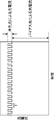
- FIG. 6 is a diagram illustrating an example of a graph of the photocurrent output from the solar cell 11.
- the solar cell 11 includes light (bias light) emitted from the light source 9 and monochromatic light (monochromatic light pulse, modulation) that is turned on / off at a predetermined period (period T) by the optical blade 6a. Light) is superimposed. Therefore, as shown in this graph, the photocurrent output from the solar cell 11 includes a photocurrent caused by bias light and a photocurrent caused by a monochromatic light pulse incident at a predetermined period T.
- the lock-in amplifier 12 detects the photocurrent generated by the monochromatic light pulse shown in FIG. 6 by synchronizing with the predetermined period T, and ⁇ I shown in FIG. 5, that is, the change ⁇ I of the short-circuit current when the irradiation intensity changes ⁇ E. Output. Further, the DC amplifier 13 outputs the photocurrent due to the bias light shown in FIG. 4, that is, the value of the short-circuit current of the solar cell 11 indicated by the vertical axis of the graph of the reference symbol Fa shown in FIG.
- the arithmetic control unit 15 calculates EAM1.5 ⁇ ( ⁇ ) of the solar cell 11 from ⁇ I acquired from the lock-in amplifier 12, ⁇ E acquired from the DC amplifier 14, and the short-circuit current I acquired from the DC amplifier 13.
- the spectral sensitivity of the solar cell 11 by light is calculated, and the spectral light source drive controller 1 and the like are controlled to control the entire spectral sensitivity measuring apparatus 100.
- a method for calculating spectral sensitivity will be described in the section ⁇ Method for calculating spectral sensitivity>.
- the data input / output unit 16 is a so-called external interface such as a USB (Universal Serial Bus) port for exchanging data with an external device
- the data storage unit 17 may be, for example, a RAM (Random It consists of volatile storage elements such as Access Memory (ROM), non-volatile storage elements such as ROM (Read Only Memory) and rewritable EEPROM (Electrically Erasable Programmable Read Only Memory), hard disk, etc., and the operation control unit 15 operates. It stores the programs and data necessary to do it.
- the setting unit 18 is a device that inputs various data such as a command for starting the spectral sensitivity measurement process and parameters for the control unit such as the spectral light source drive control unit 1 necessary for the processing to the spectral sensitivity measurement apparatus 100. is there. For example, a keyboard or a mouse.
- the display unit 19 is a device that outputs (presents) the command and data input from the setting unit 18 and the spectral sensitivity value calculated by the calculation control unit 15.
- a display device such as a CRT (Cathode Ray Tube) display, an LCD (Liquid Crystal Display), an organic EL (Electro-Luminescence) display, a plasma display, or a printing device such as a printer.
- the calculation control unit 15, the data input / output unit 16, the data storage unit 17, the setting unit 18, the display unit 19, and the like of the spectral sensitivity measuring apparatus 100 are configured by a computer including a microprocessor, a memory, and its peripheral circuits, for example.
- the microprocessor is a so-called CPU (Central Processing Unit) or the like, and by executing a program stored in the memory, the spectral sensitivity measuring apparatus 100 functionally includes the arithmetic control unit 15 to the display unit 19 and the like. To prepare.
- CPU Central Processing Unit
- I ij fluctuates.
- the spectral sensitivity measuring apparatus 100 estimates a value S (I i , ⁇ j ) at a desired short-circuit current I i from the series of measured spectral sensitivities S t (I ij , ⁇ j ).
- the spectral sensitivity S (I i , ⁇ ) of the short-circuit current I i in that wavelength range Can be requested.
- the spectral sensitivity measuring apparatus 100 has a plurality of different short-circuit currents I ij at a certain wavelength ⁇ i and spectral sensitivity St (I ij , ⁇ j when each short-circuit current I ij is measured.
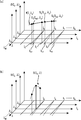
- FIG. 7A is a graph in which the wavelength ⁇ j , the short-circuit current I i, and the spectral sensitivity S (I i , ⁇ j ) are assigned to the axes orthogonal to each other.
- the spectral sensitivity measuring apparatus 100 scans a desired wavelength range while changing the wavelength (predetermined narrow wavelength band) from the wavelength ⁇ 0 to ⁇ M , and sequentially measures the spectral sensitivity.
- FIG. 7B is a diagram showing the spectral sensitivity S (I 0 , ⁇ ) when the short-circuit current is I 0 . In the graph of FIG.
- the broken line indicating the short-circuit current I i indicates that the short-circuit current initially set fluctuates gradually as the spectral sensitivity is measured sequentially from the wavelength ⁇ 0 to ⁇ M without the bias light being stabilized.
- the solid line indicates the case where the initially set short-circuit current does not fluctuate.
- the spectral sensitivity when the short-circuit currents I 0 , I 1 , and I 2 at the wavelength ⁇ 2 are considered. It is assumed that the short-circuit current I 0 gradually changes to I 02 as indicated by a broken line while measuring the spectral sensitivity while changing the wavelength. Similarly, it is assumed that the short-circuit current I 1 is I 12 and the short-circuit current I 2 is I 22 .
- the respective spectral sensitivities at the short-circuit currents I 02 , I 12 , and I 22 are St (I 02 , ⁇ 2 ), St (I 12 , ⁇ 2 ), and St (I 22 , ⁇ 2 ).
- the spectral sensitivity measuring apparatus 100 includes (I 02 , St (I 02 , ⁇ 2 )), (I 12 , St (I 12 , ⁇ 2 )), (I 22 , St (I 22 , The interpolation polynomial f 2 (I, ⁇ 2 ) is obtained from ⁇ 2 )).
- the spectral sensitivity measuring apparatus 100 can obtain the spectral sensitivity S (I 0 , ⁇ 2 ) at the time of the short-circuit current I 0 from the interpolation polynomial f 2 (I 0 , ⁇ 2 ).
- the apparatus 100 can obtain the spectral sensitivity S (I i , ⁇ ) at a constant short-circuit current I i over a desired wavelength range.
- S (I i , ⁇ j ) is estimated.
- FIG. 8 is a flowchart showing the spectral sensitivity measurement process of the spectral sensitivity measuring apparatus 100.
- the spectral sensitivity at N + 1 short-circuit currents is measured in a desired wavelength range at M + 1 wavelengths (narrow wavelength width).
- the spectral sensitivity S (I, ⁇ ) at each of the N + 1 short-circuit currents is calculated (see FIG. 7A).
- control parameter value ⁇ 0 of the light source 9 is determined so that the irradiance E b of the bias light emitted from the light source 9 is substantially equal to the light E AM1.5 ⁇ ( ⁇ ) of the standard test condition.
- the obtained control parameter value ⁇ 0 is set in the bias light source drive controller 8.
- the control parameter of the light source 9 here is a parameter for controlling the light amount of the light source 9 such as current and voltage of the light source 9.
- the calculation control unit 15 controls the spectral light source drive control unit 1 and the bias light source drive control unit 8 to control the light source 2 and the light source. 9 starts light irradiation, and 0 (zero) is set to the index i of the short-circuit current I (step S10).
- step S15 the calculation control unit 15, the irradiance ⁇ E irradiance measurement unit 10 has measured (lambda j), obtained through the DC amplifier 14 (step S15), and the change in short-circuit current from the lock-in amplifier 12 [Delta] I ( ( ⁇ j ) is acquired (step S16).
- step S18 N
- the arithmetic control unit 15 adds 1 to j (step S19).
- step S18 Y
- the processing in steps S13 to S19 is performed. Is repeated. If the stability of the bias light emitted from the light source 9 is not good while the processes in steps S13 to S19 are repeated, I 0 j is not constant.
- the arithmetic control unit 15 repeats the processing from steps S23 to S25 until j becomes M or more (step S24: Y).
- E AM1.5 ⁇ ( ⁇ ) it is not limited to E AM1.5 ⁇ ( ⁇ ), and it is also possible to calculate a short-circuit current when an arbitrary spectral irradiance E ⁇ ( ⁇ ) is virtually irradiated to the solar cell. .
- a spectral sensitivity measuring device includes a light source unit capable of individually irradiating a solar cell to be measured with a plurality of irradiation lights having different light amounts superimposed on light of a narrow wavelength band, and the plurality
- the measurement unit that measures the short-circuit current and spectral sensitivity of the solar cell when receiving any one of the irradiation lights, and the measurement when sequentially irradiating the plurality of irradiation lights individually
- the spectral sensitivity of the predetermined narrow wavelength band when the desired short-circuit current is measured is calculated based on the respective short-circuit currents measured in the unit and the spectral sensitivity when the short-circuit current is measured.
- a spectral sensitivity calculation unit is calculated based on the respective short-circuit currents measured in the unit.
- the spectral sensitivity measuring apparatus scans the solar cell to be measured by changing the wavelength of light in a narrow wavelength band within a predetermined wavelength range, and superimposes the light on the narrow wavelength band.
- a light source unit capable of individually irradiating a plurality of bias lights having different light amounts, and a short-circuit current and spectral sensitivity of the solar cell when receiving any one of the plurality of bias lights
- a measurement unit that superimposes light in a narrow wavelength range of light in a narrow wavelength band in the scan, and individually irradiates bias light having different light amounts.
- Spectral sensitivity for calculating the spectral sensitivity of the predetermined narrow wavelength band when a desired short-circuit current is measured based on each measured short-circuit current and the spectral sensitivity when the short-circuit current is measured Calculation And a part.
- the spectral sensitivity calculation unit measures a desired short-circuit current using an interpolation formula based on the short-circuit current and spectral sensitivity measured by the measurement unit. Then, the spectral sensitivity of the predetermined narrow wavelength band is calculated.
- mode is the light source part which can irradiate the several solar light which each overlaps with the light of a narrow wavelength band, and each light quantity differs separately to the solar cell of measurement object
- a spectral sensitivity measuring method used in a spectral sensitivity measuring apparatus comprising: a measurement of measuring a short-circuit current and spectral sensitivity of the solar cell when receiving any one of the plurality of irradiation lights A desired short-circuit current based on each step, and each short-circuit current measured in the measurement step and the spectral sensitivity when the short-circuit current is measured when the plurality of irradiation lights are sequentially irradiated individually.
- a spectral sensitivity measurement method is a spectral sensitivity measurement method for a solar cell, wherein the solar cell to be measured is scanned by changing the wavelength of light in a narrow wavelength band within a predetermined wavelength range.
- An irradiation step of individually irradiating a plurality of bias lights having different light amounts superimposed on the light in the narrow wavelength band, and the sun when receiving any one of the plurality of bias lights A measurement step for measuring each short-circuit current and each spectral sensitivity of the battery, and superimposing light in one of the narrow wavelength ranges of the light in the narrow wavelength band in the scanning, and applying bias light having different light amounts.
- the desired short-circuit current was measured based on each short-circuit current measured in the measurement step and the spectral sensitivity when the short-circuit current was measured. And a spectral sensitivity calculating a spectral response of said predetermined narrow wavelength band when.
- the spectral sensitivity measuring apparatus and the spectral sensitivity measuring method having such a configuration, when light of a predetermined narrow wavelength band is superimposed and a plurality of irradiation lights (bias lights) having different amounts of light are individually applied to the solar cell, Calculate the spectral sensitivity of the desired short-circuit current based on each measured short-circuit current and its spectral sensitivity, so calculate the spectral sensitivity even when the desired short-circuit current is not measured Is possible. Therefore, even if the short-circuit current fluctuates because the bias light is not stabilized while measuring the spectral sensitivity, the spectral sensitivity at the desired short-circuit current can be obtained.
- Spectral sensitivity measurement device calculates spectral sensitivity S (I i , ⁇ ) at desired short-circuit current I i even if the short-circuit current fluctuates because the bias light is not stable while measuring the spectral sensitivity. Is possible.
- the present invention is capable of obtaining a spectral sensitivity S (I i , ⁇ ) at a desired short-circuit current I i even if the short-circuit current fluctuates because the bias light is not stabilized while measuring the spectral sensitivity.
- a sensitivity measuring apparatus and method can be provided.
Landscapes
- Photovoltaic Devices (AREA)
- Investigating Or Analysing Materials By Optical Means (AREA)
- Photometry And Measurement Of Optical Pulse Characteristics (AREA)
- Testing Of Optical Devices Or Fibers (AREA)
Abstract
分光感度測定装置は、狭波長帯域の光と重畳して、光量がそれぞれ異なる複数の照射光のうちのいずれかの照射光を受けたときの、前記太陽電池の短絡電流と分光感度とを測定し、前記複数の照射光を順次個別に照射したときの、前記測定部で測定されたそれぞれの短絡電流と、当該短絡電流が測定されたときの分光感度とに基づいて、所望する短絡電流が測定されたとしたときの前記所定の狭波長帯域の分光感度を算出する分光感度算出部とを備える。そのため、このような分光感度測定装置は、分光感度を測定している間に照射光が安定せずに短絡電流が変動したとしても、所望する短絡電流における分光感度を求めることができる。
Description
本発明は、太陽電池の分光感度を求めるための装置および方法に関する。
近年、太陽電池は広く普及し、メーカ間、製品間の競争が激しくなっている。また、その組成も、単結晶シリコンから、アモルファスシリコン、薄膜シリコン、有機化合物等の多くの種類が開発されている。
太陽電池は、材料及び構造に起因する固有の分光感度特性を有する。従って、その光電変換特性は、性能評価用の照射光の分光放射照度に大きく依存することになる。そこで、これらの太陽電池の光電変換効率を公正に評価するために、評価方法が、IEC60904やJIS(C8905~C8991)で定義されている。太陽電池の性能測定は、国際的に協定された標準試験条件の下で、基準太陽光の分光放射照度(=E(λ))に近似させた分光放射照度L(λ)を持つソーラーシミュレータを用いて屋内で実施されることが多い。
このソーラーシミュレータの分光放射照度は、基準太陽光と完全には一致しておらず、異なるメーカ間ではもちろん、同じメーカにおいても機差が存在している。そのため、分光感度特性が同じ太陽電池であっても、異なるソーラーシミュレータで測定すると、太陽電池の発電量が異なってしまう。図2は、前記の基準太陽光の分光放射照度E(λ)を示すものであり、IEC60904に示されたものである。また、図3には、ソーラーシミュレータの分光放射照度L(λ)の一例を示す。図2において、横軸は、nm単位で表す波長を示し、縦軸は、μW/cm2/nm単位で表す照度を示す。また、図3において、横軸はnm単位で表す波長を示し、縦軸は、μW/cm2/nm単位で表す照度を示す。
そこで、測定者は、例えば、産業技術総合技術研究所(=国際的に統一された基準太陽光スペクトル等を持っている国立またはそれに準じる機関)等の公的機関に、サンプルとなる太陽電池を送付して測定を依頼する。それに応じてこれらの公的機関は、所有している限りなく基準太陽光に近い高近似のソーラーシミュレータを用いることによって自然太陽光AM1.5、100mW/cm2におけるそのサンプルの短絡電流ISTCを求め、その測定値(=A)を記載して測定者に返送する。
これを受けて測定者は、返送されて来たサンプルを、以降、自社の基準セルとして、ソーラーシミュレータの光量調整用に使用する。すなわち、測定者は、ソーラーシミュレータの照射光を基準セルに照射し、その短絡電流Iが前記測定値Aとなるように、ソーラーシミュレータの光量を調整する。そして、実際に測定すべき(検査対象の製品の)太陽電池の特性を測定する。これは、前述のように基準太陽光の分光スペクトルを厳密に再現することは困難であるが、可能な限り、各社のソーラーシミュレータをそれに合せ込むための手法である。
ところが、上述の手法では、基準セルを用いてソーラーシミュレータの校正を行う場合、事前に測定者がサンプルを作成して産業技術総合技術研究所等の公的機関に送付し、公的機関によって測定された短絡電流の測定値とサンプルとを受け取る必要がある。そのことは、手間や、時間、費用がかかってしまう。しかも、ソーラーシミュレータの校正は一度だけ行えばよいのでなく、測定すべき太陽電池の分光感度が変わる都度、新たに基準セルを作成して校正をやり直す必要がある。従って、ソーラーシミュレータの校正にかかる時間や費用は膨大なものとなっている。
そこで、ソーラーシミュレータの光量調整の際、基準セルの標準試験条件の光による短絡電流を値付けるために、すなわち、太陽電池の標準試験条件の光による短絡電流ISTCを算出する方法として、以下の方法が提案されている(非特許文献1参照)。
太陽電池の分光感度(微分分光応答)S(I,λ)と、基準セルの標準試験条件の分光放射照度EAM1.5 λ(λ)とから求めたs(I)=∫S(I,λ)・{EAM1.5 λ(λ)dλ/∫EAM1.5 λ(λ')dλ'}を用いて、以下の式Aを満足するISTCが、太陽電池の標準試験条件の光による短絡電流となる。
ESTC=∫0
ISTC 1/s(I)dI (ESTC=∫EAM1.5 λ(λ')dλ') ・・・・(式A)
J.Metzdorf"Calibrationof solar cells: The differential spectral responsivity method" Applied Optics 1 May 1987 Vol.26 No.9 P.1701
ここで、太陽電池は、図4に示すように、太陽電池に照射される照射強度が増えて、短絡電流が増加するに従い、長波長の分光感度が増加する。この様子を、図5に示す。参照符号F0で示されるグラフは、図4を模式化したグラフであり、参照符号F1、F2、F3等で示されるグラフはそれぞれ、図4の照射強度毎の分光感度を示すグラフである。図4において、横軸に、nm単位で表す波長を示し、縦軸に、A/Wで表す変換効率を示す。これらのF1、F2、F3等のグラフを、照射強度を横軸に、短絡電流を縦軸に変換すると、照射強度がΔEだけ変化した場合に短絡電流がΔI変化するグラフとなる。
ここで、線形特性の太陽電池の場合、短絡電流の変化は照射強度に依存せずに一定の値となるため、照射強度と短絡電流との関係を示すグラフは直線になる。しかし、太陽電池が非線形特性を持つ場合には、短絡電流の変化は照射強度により異なることになるため、照射強度と短絡電流との関係を示すグラフは、参照符号Faで示すような曲線のグラフになる。この例では、照射光エネルギーが増えるに従い、長波長側の感度が増えて、ΔI/ΔEの値が大きくなっている。
従って、上述の技術では、測定者は、非常に弱いバイアス光から略1.5・ESTC相当の強いバイアス光範囲で細かくバイアス光強度を変えて、そのときの分光感度S(Ii,λ) (i=0,1,2,・・・,N)を測定し、上記(式A)を満足するISTCを求めなければならない。
ここで、分光感度S(Ii,λ)の測定方法は、短絡電流Iiが測定されるバイアス光の照射を行いつつ、順次異なる単色光(実際には、数nmの狭波長帯域を持つ波長の光)を照射し、太陽電池からの電流を逐次求めるものである。そして、分光感度S(Ii,λ)は、太陽電池の特性に応じて所定の広い波長範囲で求める必要がある。例えば、CIS型太陽電池は、300nm~1300nmの範囲で光感度を持つ。
従って、ある光強度のバイアス光を照射しつつ、所定の広い波長範囲において順次異なる単色光を照射して分光感度S(Ii,λ)を測定している間、そのバイアス光は安定している必要がある。
しかし、非常に弱いバイアス光から略1.5・ESTC相当の強いバイアス光範囲で細かくバイアス光強度を変えて照射し、且つ、一定期間に亘り安定したバイアス光を照射する為には、バイアス光源の駆動制御が複雑とならざるを得ず、装置が高価になってしまう。
本発明は、上述の事情に鑑みて為された発明であり、分光感度を測定している間にバイアス光が安定せずに短絡電流が変動したとしても、所望する短絡電流Iiにおける分光感度S(Ii,λ)を求めることができる分光感度測定装置及び方法を提供することを目的とする。
本発明に係る分光感度測定装置は、測定対象の太陽電池に、狭波長帯域の光と重畳して、光量がそれぞれ異なる複数の照射光を個別に照射することが可能な光源部と、前記複数の照射光のうちのいずれかの照射光を受けたときの、前記太陽電池の短絡電流と分光感度とを測定する測定部と、前記複数の照射光を順次個別に照射したときの、前記測定部で測定されたそれぞれの短絡電流と、当該短絡電流が測定されたときの分光感度とに基づいて、所望する短絡電流が測定されたとしたときの前記所定の狭波長帯域の分光感度を算出する分光感度算出部とを備える。そのため、このような分光感度測定装置は、分光感度を測定している間に照射光が安定せずに短絡電流が変動したとしても、所望する短絡電流における分光感度を求めることができる。
上記並びにその他の本発明の目的、特徴及び利点は、以下の詳細な記載と添付図面から明らかになるであろう。
<実施形態>
以下、本発明に係る実施の一形態である分光感度測定装置を説明する。
以下、本発明に係る実施の一形態である分光感度測定装置を説明する。
実施形態の分光感度測定装置は、例えば、上記(式A)を演算する際に用いるような分光感度S(Ii,λ)を、分光感度測定中のバイアス光の時間変動を考慮して求めるものである。すなわち、実際にはバイアス光が安定していなくても、安定している場合に測定される分光感度S(Ii,λ)を求めることができる。
<構成>
図1は、分光感度測定装置100の構成を示すブロック図である。
図1は、分光感度測定装置100の構成を示すブロック図である。
この分光感度測定装置100は、バイアスの光の照射を行いつつ、単色光(実際には、数nmの狭波長帯域を持つ波長の光)を照射し、太陽電池11からの電流を逐次求めることで分光感度を測定し、EAM1.5 λ(λ)の光による太陽電池11の分光感度を算出するものである。
分光感度測定装置100は、例えば、図1に示すように、光源2、分光光源駆動制御部1、光学系3a、光学系3b、光学系3c、光学系3d、モノクロメータ4、モノクロメータ制御部5、サーボモータ6、光ブレード6a、チョッピングモータ駆動制御部7、ハーフミラー20、ハーフミラー21、光源9、バイアス光源駆動制御部8、放射照度測定部10、太陽電池11、ロックインアンプ12、DCアンプ13、DCアンプ14、演算制御部15、データ入出力部16、データ記憶部17、設定部18、及び、表示部19を備える。
光源2は、太陽電池11に光を照射するキセノンランプ等であり、分光光源駆動制御部1は、光源2の出力光の強度を制御する装置である。光学系3a、光学系3b、光学系3c、光学系3dは、その用途に応じて光を集光、又は、コリメート(平行光化)させるためのレンズ等の光学素子である。
モノクロメータ4は、広範囲の波長の光を空間的に分散させ、それをスリット等で狭い範囲の波長のみを取り出す分光器である。モノクロメータ4は、例えば、入射スリット、第1反射鏡、回折格子、第2反射鏡、及び、出射スリットを備えて構成され、入射スリットを介して入射された入射光束を第1反射鏡で回折格子へ反射し、回折格子で回折された入射光束の回折光を第2反射鏡で出射スリットへ反射する装置である。このような構成のモノクロメータ4では、回折格子等を回転させてスリットの位置に到達する光の波長を選択させることで、所望の範囲の波長のみが取り出される。モノクロメータ制御部5は、前記所望する範囲の波長を取り出すようにモノクロメータ4を制御する機能部である。
光ブレード6aは、所定の幅で径方向に延びる切欠き部が周方向に一定間隔に並んでいる円板状の部材であり、サーボモータ6は、サーボ機構において光ブレード6aをその中心を回転軸として回転させるモータである。チョッピングモータ駆動制御部7は、所定周期Tのパルス光を生成すべく、光ブレード6aが所望の速度で回転するようにサーボモータ6を制御する装置である。
ハーフミラー20、及び、ハーフミラー21は、入射した光の一部を反射し、一部を透過する光学素子であり、入射した光を2つに分配する光学素子である。光源9は、太陽電池11に光を照射するキセノンランプ等であり、バイアス光源駆動制御部8は、光源9の出力光の強度を制御する装置である。
放射照度測定部10は、ハーフミラー20による反射光(モノクロメータ4から射出された単色光)の放射照度を測定する装置であり、DCアンプ14は、放射照度測定部10で測定された、図5で示す放射照度ΔEを出力する。
太陽電池11は、測定対象の太陽電池である。
光源2から射出された光は、光学系3aを介してモノクロメータ4に入射し、モノクロメータ4で所定波長の光が切り出されて、モノクロメータ4から単色光が射出される。モノクロメータ4から射出された単色光は、光学系3bを介してハーフミラー20に入射し、入射した単色光の一部が反射されて放射照度測定部10に入射する。残余の単色光は透過して、光ブレード6aに入射する。光ブレード6aに入射した単色光は、サーボモータ6によって回転する光ブレード6aの周方向に並ぶ切欠き部によって透過又は遮光されることで所定周期TでON/OFFされてパルス化され、光学系3cを介し、ハーフミラー21を介して太陽電池11に入射する。
一方、光源9から射出された光は、光学系3dを介してハーフミラー21に入射し、ハーフミラー21で反射されたバイアス光は太陽電池11に入射する。すなわち、光源9から射出されたバイアス光は、モノクロメータ4から射出された単色光パルスと重畳されて、太陽電池11に入射する。
ロックインアンプ12、及び、DCアンプ13は太陽電池11の光電流を取り出す装置である。ここで、図6は、太陽電池11が出力する光電流のグラフの例を示す図である。太陽電池11には、後述のように、光源9から射出された光(バイアス光)と、光ブレード6aによって所定周期(周期T)でON/OFFされたパルスの単色光(単色光パルス、変調光)とが重畳された光が照射される。そのため、このグラフで示すように、太陽電池11が出力する光電流には、バイアス光による光電流と、所定周期Tで入射される単色光パルスによる光電流とが含まれている。ロックインアンプ12は、図6に示す単色光パルスによる光電流を所定周期Tと同期することで検出し、図5で示すΔI、すなわち、照射強度がΔE変化した場合の短絡電流の変化ΔIを出力する。また、DCアンプ13は、図4に示すバイアス光による光電流、すなわち、図5に示す参照符号Faのグラフの縦軸で示す太陽電池11の短絡電流の値を出力する。
演算制御部15は、ロックインアンプ12から取得したΔIと、DCアンプ14から取得したΔEと、DCアンプ13から取得した短絡電流Iとから、太陽電池11のEAM1.5 λ(λ)の光による太陽電池11の分光感度を算出し、分光光源駆動制御部1等を制御して分光感度測定装置100全体を制御する。分光感度の算出方法は、<分光感度の算出方法>の項で説明する。
データ入出力部16は、外部の機器とデータをやり取りするための、USB(Universal Serial Bus)ポート等のいわゆる外部インタフェースであり、データ記憶部17は、その用途に応じて、例えば、RAM(Random Access Memory)等の揮発性の記憶素子、ROM(Read Only Memory)や書換え可能なEEPROM(Electrically Erasable Programmable Read Only Memory)等の不揮発性の記憶素子、ハードディスク等により構成され、演算制御部15が動作するのに必要なプログラムや、データを記憶している。
設定部18は、分光感度測定処理を開始するコマンドや、処理を行う上で必要な分光光源駆動制御部1等の制御部に対するパラメータ等の各種データを、分光感度測定装置100に入力する機器である。例えば、キーボードやマウス等である。表示部19は、設定部18から入力されたコマンドやデータ、及び、演算制御部15が算出した分光感度値等を出力(提示)する機器である。例えばCRT(Cathode Ray Tube)ディスプレイ、LCD(Liquid Crystal Display)、有機EL(Electro-Luminescence)ディスプレイ、及び、プラズマディスプレイ等の表示装置やプリンタ等の印刷装置等である。
分光感度測定装置100の演算制御部15、データ入出力部16、データ記憶部17、設定部18、及び、表示部19等は、例えば、マイクロプロセッサ、メモリおよびその周辺回路を備えるコンピュータによって構成される。前記マイクロプロセッサは、いわゆるCPU(Central Processing Unit)等であり、メモリに記憶されているプログラムを実行することにより、分光感度測定装置100は、機能的に、演算制御部15~表示部19等を備えることになる。
<分光感度の算出方法>
本実施形態での分光感度の算出方法を説明する。
本実施形態での分光感度の算出方法を説明する。
分光感度測定装置100は、所定の波長λjにおいて、一連の分光感度St(Iij,λj) (i=0,1,2,・・・,N)を測定する。バイアス光が不安定な場合には、Iijは変動していることになる。実施形態では、これら測定した一連の分光感度St(Iij,λj)から、分光感度測定装置100は、所望の短絡電流Iiにおける値S(Ii,λj)を推定する。そして、所望の広い波長範囲において、波長ごとに短絡電流Iiにおける値S(Ii,λj)を推定することで、その波長範囲における短絡電流Iiの分光感度S(Ii,λ)を求めることができる。
より詳細には、分光感度測定装置100は、ある波長λiにおける、相異なる複数の短絡電流Iijと、それぞれの短絡電流Iijが測定されるときの分光感度St(Iij,λj)とから、すなわち、
(Iij, St(Iij,λj)) (i=0,1,2,・・・,N (j=0,1,2,・・・,M))
から、補間多項式fj(I,λj) (j=0,1,2,・・・,M)を求め、所望の短絡電流Iiにおけるfj(Ii,λj)を算出し、分光感度S(Ii,λj)とする。
(Iij, St(Iij,λj)) (i=0,1,2,・・・,N (j=0,1,2,・・・,M))
から、補間多項式fj(I,λj) (j=0,1,2,・・・,M)を求め、所望の短絡電流Iiにおけるfj(Ii,λj)を算出し、分光感度S(Ii,λj)とする。
図7を用いて、分光感度の算出方法を説明する。図7(a)は、波長λjと、短絡電流Iiと、分光感度S(Ii,λj)とをそれぞれ互いに直交する各軸に割り当てたグラフである。分光感度測定装置100は、波長λ0からλMへと、波長(所定の狭波長帯域)を変えながら、所望する波長範囲を走査(スキャン)して、分光感度を、順に測定していくものとする。また、図7(b)は、短絡電流I0のときの分光感度S(I0,λ)を示す図である。図7のグラフにおいて、短絡電流Iiを示す破線は、バイアス光が安定せずに、波長λ0からλMへと順に分光感度を測定していくにつれて最初に設定した短絡電流が徐々に変動している様子を示し、実線は、最初に設定した短絡電流が変動しない場合を示す。
ここで、波長λ2において、短絡電流I0、I1、I2のときの分光感度を考える。短絡電流I0は、波長をかえながら分光感度を測定している間に、破線で示すように徐々に変動してI02になっているものとする。同様に、短絡電流I1は、I12になり、短絡電流I2は、I22になっているものとする。
短絡電流I02、I12、I22のときのそれぞれの分光感度は、St(I02,λ2)、St(I12,λ2)、St(I22,λ2)となる。分光感度測定装置100は、ここで、(I02, St(I02,λ2))、(I12, St(I12,λ2))、(I22, St(I22,λ2))から補間多項式f2(I,λ2)を求める。そして、分光感度測定装置100は、短絡電流I0のときの分光感度S(I0,λ2)を、補間多項式f2(I0,λ2)から求めることができる。
このように、分光感度測定装置100は、波長λ毎に、fj(I0,λj) (j=0,1,2,・・・,M)を求め、短絡電流I0のときの分光感度S(I0,λj)を求めれば、図7(b)に示すように、短絡電流I0のときの分光感度S(I0,λ)を求めることができる。すなわち、波長ごとにIijが変化しても、すなわちバイアス光が安定していなくても、所定の短絡電流Iiにおける値S(Ii,λj)を求めることができるので、分光感度測定装置100は、所望の波長域に亘って、一定の短絡電流Iiにおける分光感度S(Ii,λ)を求めることができることになる。
以下、より詳細に説明する。
(Ii j, St(Ii j,λj)), (Ii+1 j, St(Ii+1 j,λj)), (Ii+2 j, St(Ii+2 j,λj))を通る以下の2次補間式の、係数αij, βij, γijが算出される。
fj(I,λj)=αij・I2 +βij・I +γij (Iは、Ii j, Ii+1 j, Ii+2 jの近傍のIである。)
(i=0,1,2,・・・,N (j=0,1,2,・・・,M))
fj(I,λj)のIにIiが代入され
S(Ii,λj)=fj(Ii,λj) (i=0,1,2,・・・,N (j=0,1,2,・・・,M))
とされることでS(Ii,λj)を推定される。
fj(I,λj)=αij・I2 +βij・I +γij (Iは、Ii j, Ii+1 j, Ii+2 jの近傍のIである。)
(i=0,1,2,・・・,N (j=0,1,2,・・・,M))
fj(I,λj)のIにIiが代入され
S(Ii,λj)=fj(Ii,λj) (i=0,1,2,・・・,N (j=0,1,2,・・・,M))
とされることでS(Ii,λj)を推定される。
尚、短絡電流Iiと分光感度S(Ii,λj)を用いた補間式は、上記の2次補間式に限定するものではない。より簡便には、
ΔIij=Iij -Ii
(i=0,1,2,・・・,N (j=0,1,2,・・・,M))
が算出され、1次近似式
S(Ii,λj)=St(Iij,λj)-ΔIij・{∂S(Iij,λj)/∂I}
において、
∂S(Iij,λj)/∂Iを{S(Iij,λj)-S(Ii+1 j,λj)}/(Iij-Ii+1 j)で近似することによりS(Ii,λj)を推定してもよい。
ΔIij=Iij -Ii
(i=0,1,2,・・・,N (j=0,1,2,・・・,M))
が算出され、1次近似式
S(Ii,λj)=St(Iij,λj)-ΔIij・{∂S(Iij,λj)/∂I}
において、
∂S(Iij,λj)/∂Iを{S(Iij,λj)-S(Ii+1 j,λj)}/(Iij-Ii+1 j)で近似することによりS(Ii,λj)を推定してもよい。
<動作>
図8は、分光感度測定装置100の分光感度測定処理を示すフローチャートである。実施形態では、所望の波長範囲をM+1個の波長(狭波長幅)において、N+1個の短絡電流における分光感度を測定する。そして、N+1個の短絡電流それぞれにおける分光感度S(I,λ)を算出する(図7(a)参照)。また、M+1個の各波長λj (j=0,1,2,・・・,M)、及び、N+1個の短絡電流Ii (i=0,1,2,・・・,N)は、予め決められているものとする。
図8は、分光感度測定装置100の分光感度測定処理を示すフローチャートである。実施形態では、所望の波長範囲をM+1個の波長(狭波長幅)において、N+1個の短絡電流における分光感度を測定する。そして、N+1個の短絡電流それぞれにおける分光感度S(I,λ)を算出する(図7(a)参照)。また、M+1個の各波長λj (j=0,1,2,・・・,M)、及び、N+1個の短絡電流Ii (i=0,1,2,・・・,N)は、予め決められているものとする。
まず、光源9から照射されるバイアス光の放射照度Ebが略標準試験条件の光EAM1.5 λ(λ)になるように、光源9の制御パラメータの値β0が求められ、この求められた制御パラメータの値β0がバイアス光源駆動制御部8に設定される。ここでいう光源9の制御パラメータとは光源9の電流、電圧など光源9の光量を制御するパラメータである。
測定対象の太陽電池11がセットされ、測定開始コマンドが設定部18から入力されると、演算制御部15は、分光光源駆動制御部1及びバイアス光源駆動制御部8を制御して光源2及び光源9に光照射を開始させ、短絡電流Iのインデックスiに0(ゼロ)を設定する(ステップS10)。
次に、太陽電池11の短絡電流、すなわち、DCアンプ13から出力される短絡電流が短絡電流Ii (i=0)とほぼ等しくなるように、バイアス光が調整される(ステップS11)。
そして、演算制御部15は、波長λのインデックスjに0(ゼロ)を設定し、(ステップS12)、再度、波長λj (j=0)のときの短絡電流Iij (i=0,j=0)をDCアンプ13から取得する(ステップS13)。そして、演算制御部15は、モノクロメータ制御部5を制御して、モノクロメータ4から波長λj (j=0)の単色光(詳細には波長帯域Δλjの準単色光)を出射させる(ステップS14)。尚、ステップS13とステップS14は、順番が逆でもよい。
次に、演算制御部15は、放射照度測定部10が測定した放射照度ΔE(λj)を、DCアンプ14を介して取得し(ステップS15)、ロックインアンプ12から短絡電流の変化ΔI(λj)を取得する(ステップS16)。
そして、演算制御部15は、波長λjにおける短絡電流Iijの分光感度St(Iij,λj)=ΔI(λj)/ΔE(λj) (i=0,j=0)を算出する(ステップS17)。
ここで、jがM以下である場合、すなわち、所望の波長範囲の分光感度を測定していない場合は(ステップS18:N)、演算制御部15は、jに1を加算して(ステップS19)、波長λj (j=1)のときの短絡電流Iij (i=0,j=1)をDCアンプ13から取得する(ステップS13)。そして、演算制御部15は、モノクロメータ4から波長λj (j=1)の単色光を出射させ(ステップS14)、放射照度ΔE(λj)、ΔI(λj)を取得し(ステップS15、S16)、波長λjにおける短絡電流Iijの分光感度St(Iij,λj) (i=0,j=1)を算出する(ステップS17)。
このように、jがM以上になるまで、すなわち、短絡電流Ii (i=0)における所望の波長範囲での分光感度を測定するまで(ステップS18:Y)、ステップS13~ステップS19の処理が繰り返される。このステップS13~ステップS19の処理を繰り返している間、光源9から照射されるバイアス光の安定性が良くない場合、I0 jは一定ではないことになる。
短絡電流Ii (i=0)における所望の波長範囲での分光感度の測定が終了すると(ステップS18:Y)、演算制御部15は、i=0であるので(ステップS20:N)、iに1を加算して(ステップS21)、太陽電池11の短絡電流が短絡電流Ii (i=1)とほぼ等しくなるように、バイアス光を調整する(ステップS11)。そして、jに0を設定する(ステップS12)。そして、短絡電流Ii (i=1)において、波長λj (j=0)から測定を開始する。
演算制御部15は、ステップS13~ステップS19の処理を繰り返し、短絡電流Ii (i=1)における所望の波長範囲での分光感度を測定する(ステップS18:Y)。
ステップS20において、演算制御部15は、iがN以上になるまで(ステップS20:Y)、ステップS11~ステップS20の処理を繰り返す。すなわち、各波長λj (j=0,1,2,・・・,M)の各短絡電流Ii (i=0,1,2,・・・,N)の分光感度が測定されることになる。
ステップS20において、演算制御部15は、iがN以上になったら(ステップS20:Y)、jに0を設定し(ステップS22)、波長λj (j=0)における、補間多項式f(I,λ0)を求め、各短絡電流Ii (i=0,1,2,・・・,N)の分光感度S(Ii,λ0)を算出する(ステップS23)。
次に、演算制御部15は、jに1を加算し(ステップS25)、波長λj (j=1)における、補間多項式f(I,λ1)を求め、各短絡電流Ii (i=0,1,2,・・・,N)の分光感度S(Ii,λ0)を算出する(ステップS23)。演算制御部15は、jがM以上になるまで(ステップS24:Y)、ステップS23~S25までの処理を繰り返す。
演算制御部15は、M+1個の波長(j=0,1,2,・・・,M)において、N+1個の短絡電流Ii(i=0,1,2,・・・,N)における分光感度S(Ii,λj)を算出すると(ステップS24:Y)、分光感度測定処理を終了する。
以上のように、波長ごとの分光感度を測定している間に短絡電流が変化してしまったとても、安定しているとした場合のIiにおけるS(Ii,λj)が求められたことになる。従って、∫S(Ii,λj)・{EAM1.5 λ(λ)/ESTC}dλを用いてEAM1.5 λ(λ)のときの短絡電流を正しく求めることが可能となる。
尚、EAM1.5 λ(λ)に限定されるものではなく、任意の分光放射照度Eλ(λ)を仮想的に太陽電池に照射したときの、短絡電流を算出することも可能である。
本明細書は、上記のように様々な態様の技術を開示しているが、そのうち主な技術を以下に示す。
一態様に係る分光感度測定装置は、測定対象の太陽電池に、狭波長帯域の光と重畳して、光量がそれぞれ異なる複数の照射光を個別に照射することが可能な光源部と、前記複数の照射光のうちのいずれかの照射光を受けたときの、前記太陽電池の短絡電流と分光感度とを測定する測定部と、前記複数の照射光を順次個別に照射したときの、前記測定部で測定されたそれぞれの短絡電流と、当該短絡電流が測定されたときの分光感度とに基づいて、所望する短絡電流が測定されたとしたときの前記所定の狭波長帯域の分光感度を算出する分光感度算出部とを備える。
また、他の一態様に係る分光感度測定装置は、測定対象の太陽電池に、所定の波長範囲で狭波長帯域の光の波長を変えることによって走査し、前記狭波長帯域の光と重畳して、光量がそれぞれ異なる複数のバイアス光を個別に照射することが可能な光源部と、前記複数のバイアス光のうちのいずれかのバイアス光を受けたときの、前記太陽電池の短絡電流と分光感度とを測定する測定部と、前記走査における狭波長帯域の光のうちのいずれかの狭波長範囲の光を重畳して、光量がそれぞれ異なるバイアス光を個別に照射したときに、前記測定部で測定されたそれぞれの短絡電流と、当該短絡電流が測定されたときの分光感度とに基づいて、所望する短絡電流が測定されたとしたときの前記所定の狭波長帯域の分光感度を算出する分光感度算出部とを備える。
また、他の一態様では、上述の分光感度測定装置において、前記分光感度算出部は、前記測定部が測定した短絡電流と分光感度とに基づいた補間式を用いて、所望する短絡電流が測定されたとしたときの前記所定の狭波長帯域の分光感度を算出する。
そして、他の一態様に係る分光感度測定方法は、測定対象の太陽電池に、狭波長帯域の光と重畳して、光量がそれぞれ異なる複数の照射光を個別に照射することが可能な光源部を備える分光感度測定装置で用いられる分光感度測定方法であって、前記複数の照射光のうちのいずれかの照射光を受けたときの、前記太陽電池の短絡電流と分光感度とを測定する測定ステップと、前記複数の照射光を順次個別に照射したときの、前記測定ステップで測定されたそれぞれの短絡電流と、当該短絡電流が測定されたときの分光感度とに基づいて、所望する短絡電流が測定されたとしたときの前記所定の狭波長帯域の分光感度を算出する分光感度算出ステップとを備える。
また、他の一態様に係る分光感度測定方法は、太陽電池の分光感度測定方法であって、測定対象の太陽電池に、所定の波長範囲で狭波長帯域の光の波長を変えることによって走査し、前記狭波長帯域の光と重畳して、光量がそれぞれ異なる複数のバイアス光を個別に照射する照射ステップと、前記複数のバイアス光のうちのいずれかのバイアス光を受けたときの、前記太陽電池のそれぞれの短絡電流とそれぞれの分光感度とを測定する測定ステップと、前記走査における狭波長帯域の光のうちのいずれかの狭波長範囲の光を重畳して、光量がそれぞれ異なるバイアス光を個別に照射したときに、前記測定ステップで測定されたそれぞれの短絡電流と、当該短絡電流が測定されたときの分光感度とに基づいて、所望する短絡電流が測定されたとしたときの前記所定の狭波長帯域の分光感度を算出する分光感度算出ステップとを備える。
このような構成の分光感度測定装置及び分光感度測定方法では、所定の狭波長帯域の光が重畳され、光量がそれぞれ異なる複数の照射光(バイアス光)を個別に太陽電池に照射した場合に、測定されたそれぞれの短絡電流とその分光感度とに基づいて、所望する短絡電流の分光感度を算出するので、所望する短絡電流が測定されていない場合であっても、その分光感度を算出することが可能となる。従って、分光感度を測定している間にバイアス光が安定せずに短絡電流が変動したとしても、所望する短絡電流における分光感度を求めることが可能となる。また、例えば、所望する短絡電流における、広い波長範囲の分光感度を求めようとする場合では、重畳する光の波長帯域を変えて測定し、波長帯域毎に所望する短絡電流における分光感度を算出すればよい。
分光感度測定装置は、分光感度を測定している間バイアス光が安定しておらずに短絡電流が変動したとしても、所望する短絡電流Iiにおける分光感度S(Ii,λ)を求めることが可能となる。
この出願は、2011年6月14日に出願された日本国特許出願特願2011-131955を基礎とするものであり、その内容は、本願に含まれるものである。
本発明を表現するために、上述において図面を参照しながら実施形態を通して本発明を適切且つ十分に説明したが、当業者であれば上述の実施形態を変更および/または改良することは容易に為し得ることであると認識すべきである。したがって、当業者が実施する変更形態または改良形態が、請求の範囲に記載された請求項の権利範囲を離脱するレベルのものでない限り、当該変更形態または当該改良形態は、当該請求項の権利範囲に包括されると解釈される。
本発明は、分光感度を測定している間にバイアス光が安定せずに短絡電流が変動したとしても、所望する短絡電流Iiにおける分光感度S(Ii,λ)を求めることができる分光感度測定装置及び方法を提供することができる。
Claims (5)
- 測定対象の太陽電池に、狭波長帯域の光と重畳して、光量がそれぞれ異なる複数の照射光を個別に照射することが可能な光源部と、
前記複数の照射光のうちのいずれかの照射光を受けたときの、前記太陽電池の短絡電流と分光感度とを測定する測定部と、
前記複数の照射光を順次個別に照射したときの、前記測定部で測定されたそれぞれの短絡電流と、当該短絡電流が測定されたときの分光感度とに基づいて、所望する短絡電流が測定されたとしたときの前記所定の狭波長帯域の分光感度を算出する分光感度算出部と
を備えることを特徴とする分光感度測定装置。 - 測定対象の太陽電池に、所定の波長範囲で狭波長帯域の光の波長を変えることによって走査し、前記狭波長帯域の光と重畳して、光量がそれぞれ異なる複数のバイアス光を個別に照射することが可能な光源部と、
前記複数のバイアス光のうちのいずれかのバイアス光を受けたときの、前記太陽電池の短絡電流と分光感度とを測定する測定部と、
前記走査における狭波長帯域の光のうちのいずれかの狭波長範囲の光を重畳して、光量がそれぞれ異なるバイアス光を個別に照射したときに、前記測定部で測定されたそれぞれの短絡電流と、当該短絡電流が測定されたときの分光感度とに基づいて、所望する短絡電流が測定されたとしたときの前記所定の狭波長帯域の分光感度を算出する分光感度算出部と
を備えることを特徴とする分光感度測定装置。 - 前記分光感度算出部は、前記測定部が測定した短絡電流と分光感度とに基づいた補間式を用いて、所望する短絡電流が測定されたとしたときの前記所定の狭波長帯域の分光感度を算出する
ことを特徴とする請求項1又は2に記載の分光感度測定装置。 - 測定対象の太陽電池に、狭波長帯域の光と重畳して、光量がそれぞれ異なる複数の照射光を個別に照射することが可能な光源部を備える分光感度測定装置で用いられる分光感度測定方法であって、
前記複数の照射光のうちのいずれかの照射光を受けたときの、前記太陽電池の短絡電流と分光感度とを測定する測定ステップと、
前記複数の照射光を順次個別に照射したときの、前記測定ステップで測定されたそれぞれの短絡電流と、当該短絡電流が測定されたときの分光感度とに基づいて、所望する短絡電流が測定されたとしたときの前記所定の狭波長帯域の分光感度を算出する分光感度算出ステップと
を備えることを特徴とする分光感度測定方法。 - 太陽電池の分光感度測定方法であって、
測定対象の太陽電池に、所定の波長範囲で狭波長帯域の光の波長を変えることによって走査し、前記狭波長帯域の光と重畳して、光量がそれぞれ異なる複数のバイアス光を個別に照射する照射ステップと、
前記複数のバイアス光のうちのいずれかのバイアス光を受けたときの、前記太陽電池のそれぞれの短絡電流とそれぞれの分光感度とを測定する測定ステップと、
前記走査における狭波長帯域の光のうちのいずれかの狭波長範囲の光を重畳して、光量がそれぞれ異なるバイアス光を個別に照射したときに、前記測定ステップで測定されたそれぞれの短絡電流と、当該短絡電流が測定されたときの分光感度とに基づいて、所望する短絡電流が測定されたとしたときの前記所定の狭波長帯域の分光感度を算出する分光感度算出ステップと
を備えることを特徴とする分光感度測定方法。
Priority Applications (1)
| Application Number | Priority Date | Filing Date | Title |
|---|---|---|---|
| JP2013520426A JP5761343B2 (ja) | 2011-06-14 | 2012-06-08 | 分光感度測定装置、および、分光感度測定方法 |
Applications Claiming Priority (2)
| Application Number | Priority Date | Filing Date | Title |
|---|---|---|---|
| JP2011-131955 | 2011-06-14 | ||
| JP2011131955 | 2011-06-14 |
Publications (1)
| Publication Number | Publication Date |
|---|---|
| WO2012172767A1 true WO2012172767A1 (ja) | 2012-12-20 |
Family
ID=47356774
Family Applications (1)
| Application Number | Title | Priority Date | Filing Date |
|---|---|---|---|
| PCT/JP2012/003766 Ceased WO2012172767A1 (ja) | 2011-06-14 | 2012-06-08 | 分光感度測定装置、および、分光感度測定方法 |
Country Status (2)
| Country | Link |
|---|---|
| JP (1) | JP5761343B2 (ja) |
| WO (1) | WO2012172767A1 (ja) |
Cited By (3)
| Publication number | Priority date | Publication date | Assignee | Title |
|---|---|---|---|---|
| CN103746654A (zh) * | 2014-02-14 | 2014-04-23 | 苏州众显电子科技有限公司 | 一种带便携光源的功率表测试高倍聚光电池片装置 |
| CN103762942A (zh) * | 2014-02-11 | 2014-04-30 | 苏州众显电子科技有限公司 | 一种快速简易功率表测试高倍聚光电池片装置 |
| JP2016144253A (ja) * | 2015-01-30 | 2016-08-08 | コニカミノルタ株式会社 | 分光感度測定装置 |
Families Citing this family (1)
| Publication number | Priority date | Publication date | Assignee | Title |
|---|---|---|---|---|
| KR20120104083A (ko) | 2009-06-30 | 2012-09-20 | 톰슨 라이센싱 | 디지털 신호들을 재전송하기 위한 프로세스 |
Citations (3)
| Publication number | Priority date | Publication date | Assignee | Title |
|---|---|---|---|---|
| JPS6384078A (ja) * | 1986-09-26 | 1988-04-14 | Sharp Corp | 太陽電池の分光感度測定法 |
| JP2004281706A (ja) * | 2003-03-14 | 2004-10-07 | Japan Science & Technology Agency | Ledを用いた太陽電池の評価方法及びその評価装置 |
| WO2010058649A1 (ja) * | 2008-11-19 | 2010-05-27 | コニカミノルタセンシング株式会社 | 太陽電池評価装置および太陽電池評価方法 |
-
2012
- 2012-06-08 WO PCT/JP2012/003766 patent/WO2012172767A1/ja not_active Ceased
- 2012-06-08 JP JP2013520426A patent/JP5761343B2/ja not_active Expired - Fee Related
Patent Citations (3)
| Publication number | Priority date | Publication date | Assignee | Title |
|---|---|---|---|---|
| JPS6384078A (ja) * | 1986-09-26 | 1988-04-14 | Sharp Corp | 太陽電池の分光感度測定法 |
| JP2004281706A (ja) * | 2003-03-14 | 2004-10-07 | Japan Science & Technology Agency | Ledを用いた太陽電池の評価方法及びその評価装置 |
| WO2010058649A1 (ja) * | 2008-11-19 | 2010-05-27 | コニカミノルタセンシング株式会社 | 太陽電池評価装置および太陽電池評価方法 |
Cited By (3)
| Publication number | Priority date | Publication date | Assignee | Title |
|---|---|---|---|---|
| CN103762942A (zh) * | 2014-02-11 | 2014-04-30 | 苏州众显电子科技有限公司 | 一种快速简易功率表测试高倍聚光电池片装置 |
| CN103746654A (zh) * | 2014-02-14 | 2014-04-23 | 苏州众显电子科技有限公司 | 一种带便携光源的功率表测试高倍聚光电池片装置 |
| JP2016144253A (ja) * | 2015-01-30 | 2016-08-08 | コニカミノルタ株式会社 | 分光感度測定装置 |
Also Published As
| Publication number | Publication date |
|---|---|
| JP5761343B2 (ja) | 2015-08-12 |
| JPWO2012172767A1 (ja) | 2015-02-23 |
Similar Documents
| Publication | Publication Date | Title |
|---|---|---|
| JP4944231B2 (ja) | 太陽電池評価装置およびそれに用いられる光源評価装置 | |
| JP5223928B2 (ja) | 太陽電池評価装置および太陽電池評価方法 | |
| JP5761343B2 (ja) | 分光感度測定装置、および、分光感度測定方法 | |
| EP2790228A1 (en) | Solar cell spectral response measurement device | |
| JP2013156132A (ja) | 太陽電池評価装置および該方法 | |
| JP5626363B2 (ja) | 分光放射照度測定装置、分光放射照度測定システムおよび分光放射照度校正方法 | |
| JP4944233B2 (ja) | 太陽電池評価装置およびそれに用いられる光源評価装置 | |
| JP5696595B2 (ja) | 短絡電流測定装置、太陽電池評価装置、短絡電流測定方法、および、太陽電池評価方法 | |
| JP2005011958A (ja) | 光電変換素子の電流電圧特性の測定方法及び測定装置 | |
| JP5741774B1 (ja) | 太陽電池絶対分光感度測定装置および該方法 | |
| Garcia et al. | On the spectral response measurement of multijunction solar cells | |
| JP5900137B2 (ja) | 太陽電池評価装置および該方法 | |
| JP5772972B2 (ja) | 太陽電池評価装置、および太陽電池評価方法 | |
| JP5742835B2 (ja) | 太陽電池評価装置および太陽電池評価方法 | |
| JP5601308B2 (ja) | 太陽電池評価装置、及び、太陽電池評価方法 | |
| JP6447184B2 (ja) | 分光感度測定装置 | |
| JP5895691B2 (ja) | 太陽電池評価装置および該方法 | |
| JP5811938B2 (ja) | 太陽電池評価装置および該方法 | |
| JP6464939B2 (ja) | 分光感度測定装置及び分光感度測定方法 | |
| JP2013234895A (ja) | 太陽電池評価装置および該方法 | |
| Field | Methods and Instruments for the Characterization of Solar Cells | |
| Huang et al. | Comparison of two methods for short circuit current measurement of large size solar cell | |
| KR20230061699A (ko) | 페로브스카이트 태양전지의 양자효율 측정장치 및 그 제어방법 | |
| Witt et al. | Recent advances in synthetic calibrations of multi junction solar cells and their corresponding component cells | |
| JP2012114375A (ja) | 太陽電池評価装置および評価方法 |
Legal Events
| Date | Code | Title | Description |
|---|---|---|---|
| 121 | Ep: the epo has been informed by wipo that ep was designated in this application |
Ref document number: 12801032 Country of ref document: EP Kind code of ref document: A1 |
|
| ENP | Entry into the national phase |
Ref document number: 2013520426 Country of ref document: JP Kind code of ref document: A |
|
| NENP | Non-entry into the national phase |
Ref country code: DE |
|
| 122 | Ep: pct application non-entry in european phase |
Ref document number: 12801032 Country of ref document: EP Kind code of ref document: A1 |