WO2012172756A1 - 超音波診断装置およびそれを用いた超音波計測方法 - Google Patents
超音波診断装置およびそれを用いた超音波計測方法 Download PDFInfo
- Publication number
- WO2012172756A1 WO2012172756A1 PCT/JP2012/003723 JP2012003723W WO2012172756A1 WO 2012172756 A1 WO2012172756 A1 WO 2012172756A1 JP 2012003723 W JP2012003723 W JP 2012003723W WO 2012172756 A1 WO2012172756 A1 WO 2012172756A1
- Authority
- WO
- WIPO (PCT)
- Prior art keywords
- measurement
- frames
- measurement target
- imt
- probe
- Prior art date
Links
Images


Classifications
-
- A—HUMAN NECESSITIES
- A61—MEDICAL OR VETERINARY SCIENCE; HYGIENE
- A61B—DIAGNOSIS; SURGERY; IDENTIFICATION
- A61B8/00—Diagnosis using ultrasonic, sonic or infrasonic waves
- A61B8/52—Devices using data or image processing specially adapted for diagnosis using ultrasonic, sonic or infrasonic waves
- A61B8/5215—Devices using data or image processing specially adapted for diagnosis using ultrasonic, sonic or infrasonic waves involving processing of medical diagnostic data
- A61B8/5238—Devices using data or image processing specially adapted for diagnosis using ultrasonic, sonic or infrasonic waves involving processing of medical diagnostic data for combining image data of patient, e.g. merging several images from different acquisition modes into one image
- A61B8/5246—Devices using data or image processing specially adapted for diagnosis using ultrasonic, sonic or infrasonic waves involving processing of medical diagnostic data for combining image data of patient, e.g. merging several images from different acquisition modes into one image combining images from the same or different imaging techniques, e.g. color Doppler and B-mode
-
- A—HUMAN NECESSITIES
- A61—MEDICAL OR VETERINARY SCIENCE; HYGIENE
- A61B—DIAGNOSIS; SURGERY; IDENTIFICATION
- A61B8/00—Diagnosis using ultrasonic, sonic or infrasonic waves
- A61B8/08—Detecting organic movements or changes, e.g. tumours, cysts, swellings
- A61B8/0858—Detecting organic movements or changes, e.g. tumours, cysts, swellings involving measuring tissue layers, e.g. skin, interfaces
-
- A—HUMAN NECESSITIES
- A61—MEDICAL OR VETERINARY SCIENCE; HYGIENE
- A61B—DIAGNOSIS; SURGERY; IDENTIFICATION
- A61B8/00—Diagnosis using ultrasonic, sonic or infrasonic waves
- A61B8/08—Detecting organic movements or changes, e.g. tumours, cysts, swellings
- A61B8/0883—Detecting organic movements or changes, e.g. tumours, cysts, swellings for diagnosis of the heart
-
- A—HUMAN NECESSITIES
- A61—MEDICAL OR VETERINARY SCIENCE; HYGIENE
- A61B—DIAGNOSIS; SURGERY; IDENTIFICATION
- A61B8/00—Diagnosis using ultrasonic, sonic or infrasonic waves
- A61B8/08—Detecting organic movements or changes, e.g. tumours, cysts, swellings
- A61B8/0891—Detecting organic movements or changes, e.g. tumours, cysts, swellings for diagnosis of blood vessels
-
- A—HUMAN NECESSITIES
- A61—MEDICAL OR VETERINARY SCIENCE; HYGIENE
- A61B—DIAGNOSIS; SURGERY; IDENTIFICATION
- A61B8/00—Diagnosis using ultrasonic, sonic or infrasonic waves
- A61B8/13—Tomography
- A61B8/14—Echo-tomography
-
- A—HUMAN NECESSITIES
- A61—MEDICAL OR VETERINARY SCIENCE; HYGIENE
- A61B—DIAGNOSIS; SURGERY; IDENTIFICATION
- A61B8/00—Diagnosis using ultrasonic, sonic or infrasonic waves
- A61B8/48—Diagnostic techniques
- A61B8/483—Diagnostic techniques involving the acquisition of a 3D volume of data
-
- A—HUMAN NECESSITIES
- A61—MEDICAL OR VETERINARY SCIENCE; HYGIENE
- A61B—DIAGNOSIS; SURGERY; IDENTIFICATION
- A61B8/00—Diagnosis using ultrasonic, sonic or infrasonic waves
- A61B8/52—Devices using data or image processing specially adapted for diagnosis using ultrasonic, sonic or infrasonic waves
- A61B8/5215—Devices using data or image processing specially adapted for diagnosis using ultrasonic, sonic or infrasonic waves involving processing of medical diagnostic data
- A61B8/5223—Devices using data or image processing specially adapted for diagnosis using ultrasonic, sonic or infrasonic waves involving processing of medical diagnostic data for extracting a diagnostic or physiological parameter from medical diagnostic data
-
- A—HUMAN NECESSITIES
- A61—MEDICAL OR VETERINARY SCIENCE; HYGIENE
- A61B—DIAGNOSIS; SURGERY; IDENTIFICATION
- A61B8/00—Diagnosis using ultrasonic, sonic or infrasonic waves
- A61B8/52—Devices using data or image processing specially adapted for diagnosis using ultrasonic, sonic or infrasonic waves
- A61B8/5284—Devices using data or image processing specially adapted for diagnosis using ultrasonic, sonic or infrasonic waves involving retrospective matching to a physiological signal
-
- A—HUMAN NECESSITIES
- A61—MEDICAL OR VETERINARY SCIENCE; HYGIENE
- A61B—DIAGNOSIS; SURGERY; IDENTIFICATION
- A61B8/00—Diagnosis using ultrasonic, sonic or infrasonic waves
- A61B8/54—Control of the diagnostic device
-
- A—HUMAN NECESSITIES
- A61—MEDICAL OR VETERINARY SCIENCE; HYGIENE
- A61B—DIAGNOSIS; SURGERY; IDENTIFICATION
- A61B8/00—Diagnosis using ultrasonic, sonic or infrasonic waves
- A61B8/54—Control of the diagnostic device
- A61B8/543—Control of the diagnostic device involving acquisition triggered by a physiological signal
Definitions
- the present application relates to an ultrasonic diagnostic apparatus and an ultrasonic measurement method using the same.
- IMT Intima-MediaThickness
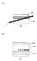
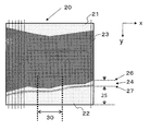
- IMT is the thickness of the intima-media complex of the vascular wall of the carotid artery, and the layer (intima 24) visible between the vascular lumen 23 and the outer membrane 25 shown in FIG. Thickness.
- the IMT generally uses an ultrasonic diagnostic apparatus, and includes a boundary between the blood vessel lumen 23 and the intima (hereinafter referred to as a lumen-intima boundary 26) and a boundary between the media and the outer membrane 25 (hereinafter referred to as a medium). This is determined by measuring the distance between the two boundaries.
- a lumen-intima boundary 26 a boundary between the blood vessel lumen 23 and the intima
- a medium a boundary between the media and the outer membrane 25
- a predetermined IMT measurement range 30 is set along the long axis direction of the carotid artery 20 (the direction in which the blood vessel has expanded), and the IMT measured in this IMT measurement range 30.
- the maximum thickness (maxIMT) and the average thickness (meanIMT) are used as IMT values.
- the IMT measurement range 30 be set to 1 cm on the distal side (head side) of the common carotid artery (CCA) in the carotid artery 20.
- the conventional ultrasonic diagnostic apparatus has a problem that accurate measurement is difficult unless it is a skilled person who has been sufficiently trained to measure the state of a blood vessel as a measurement target part.
- an ultrasonic beam is transmitted and received in a state where the probe is arranged on the neck surface so that the longitudinal direction of the carotid artery coincides with the longitudinal direction of the probe surface of the probe. .
- the ultrasonic beam transmitted from the probe is scanned so as to scan the vicinity of the center (that is, the central axis of the carotid artery) in the cross section perpendicular to the long axis direction of the carotid artery (hereinafter referred to as the short axis cross section).
- Accurate IMT measurement is performed by arranging the probe (hereinafter, the arrangement state of the probe is referred to as “the probe captures the vicinity of the center of the short-axis cross section of the blood vessel”). Can do.
- the position and shape of the carotid artery cannot be seen from the skin surface of the neck muscle, and the carotid artery itself is thin, and its position and shape vary from person to person. For this reason, it is not easy to arrange the probe at a position where the vicinity of the center in the short-axis cross section of the carotid artery can be cut. As a result, accurate IMT measurement can be performed only by skilled workers who have performed sufficient training, and IMT measurement cannot be easily performed.
- One non-limiting exemplary embodiment of the present application provides an ultrasonic diagnostic apparatus and a measurement method using the same that can easily perform accurate IMT measurement even without being an expert.
- An ultrasonic diagnostic apparatus is an ultrasonic diagnostic apparatus that is configured to be connectable to a probe having a transducer and that performs a predetermined measurement process on a measurement target region of a subject. Consists of a transmission process for driving the probe and transmitting ultrasonic waves to the subject including the measurement target part, and a received signal based on the reflected ultrasonic waves from the subject including the measurement target part received by the probe.
- the received signal processing for generating a frame to be generated is performed a plurality of times at different times to generate a plurality of the frames, and at least two or more measurement target frames to be measured are selected from the plurality of frames, Extract a measurable area where the measurement process can be performed based on each of the received signals from the measurement target parts included in at least two measurement target frames, and combine the measurable areas It allows a control unit that performs predetermined measurement processing on the measurement target region.
- An ultrasonic measurement method is an ultrasonic measurement method for performing predetermined measurement on a measurement target portion of a subject using ultrasonic waves emitted from the probe, Driving and transmitting ultrasonic waves, and received signal processing for generating a frame composed of received signals based on reflected ultrasonic waves from the subject including the measurement target portion received by the probe, Performing a plurality of times at different times, a first step of generating a plurality of frames, a second step of selecting at least two measurement target frames to be measured from the plurality of frames, and at least two Combining the measurable area with a third step of extracting a measurable area where the measurement process can be performed based on each of the received signals from the measurement target part included in the measurement target frame. And by, and a fourth step of performing predetermined measurement process corresponding to the measurement target region.
- the probe even if the probe is displaced from the correct position of the measurement target region with respect to the subject, the probe is strictly adjusted to correct the deviation. It is not necessary to adjust the position, and appropriate measurement processing can be performed by combining a plurality of measurement target frames.
- Embodiment 1 is a block diagram showing Embodiment 1 of an ultrasonic diagnostic apparatus according to the present invention. It is a flowchart which shows operation
- A) is a figure which shows the long-axis cross section of a carotid artery
- (b) is a figure which shows the time change waveform of the internal diameter of the carotid artery by the discharge of the blood from a heart.
- A) And (b) is a figure which shows the positional relationship of the probe arrange
- (A) is a top view which shows an example of the positional relationship of the probe and carotid artery at the time of IMT measurement
- (b) is a figure which shows the tomogram of a carotid artery.
- (A) is a top view which shows an example of the positional relationship of the probe and carotid artery at the time of IMT measurement
- (b) is a figure which shows the tomogram of a carotid artery.
- (A) is a top view which shows an example of the positional relationship of the probe and carotid artery at the time of IMT measurement
- (b) is a figure which shows the tomogram of a carotid artery.
- FIG. 1 is a block diagram showing Embodiment 1 of an ultrasonic diagnostic apparatus according to the present invention.
- the controller 40 includes an ultrasonic transmission / reception processor 2, a tomogram processor 3, a diastole end detector 4, a measurement target frame selector 5, a measurable region extractor 6, a measurement processor 7, a controller 8, and an image.
- a synthesis unit 9 is included.
- the ultrasonic diagnostic apparatus 100 does not include the probe 1 and a general-purpose probe 1 can be connected. However, the ultrasonic diagnostic apparatus 100 may include the probe 1.
- the ultrasonic transmission / reception processing unit 2, the measurement target frame selection unit 5, the control unit 8, and the image synthesis unit 9 are realized by, for example, known hardware using various electronic components.
- the tomographic image processing unit 3, the end diastole detection unit 4, the measurable region extraction unit 6, and the measurement processing unit 7 may be configured by software or hardware.
- the reception signal generated by the ultrasonic transmission / reception processing unit 2 may be a digital signal.
- the control unit 8 includes a computing unit such as a microcomputer and software.
- the probe 1 has an ultrasonic transducer, transmits the ultrasonic wave through the ultrasonic transducer to the subject including the measurement target portion, receives the reflected ultrasonic wave, and converts it into an electrical signal.
- the measurement target portion here refers to the IMT measurement range 30 shown in FIG.
- the ultrasonic transmission / reception processing unit 2 is configured such that the probe 1 is detachable.
- a driving pulse is supplied to the ultrasonic transducer of the probe 1 at a predetermined timing, and transmission processing is performed so that the probe transmits ultrasonic waves.
- it receives the reflected ultrasonic wave by receiving the converted electric signal from the probe 1 and performing reception processing necessary for constructing an ultrasonic tomographic image, such as amplification and detection of the electric signal. Generate a signal.
- the ultrasonic transmission / reception processing unit 2 repeatedly and continuously performs transmission processing, sequentially generates reception signals, and generates a plurality of frames from the generated reception signals.
- the term “frame” as used herein refers to a single received signal necessary for constructing a single tomographic image, or a single tomographic image constructed based on this single received signal. Point to.
- the tomographic image processing unit 3 receives the reception signal generated by the ultrasonic transmission / reception processing unit 2, performs coordinate conversion of the received signal, and sequentially constructs a tomographic image that is a two-dimensional image of the ultrasonic image for each frame. For example, tomographic images as shown in FIG. 16 are sequentially constructed. As shown in FIG. 16, by scanning the ultrasonic beam in the x direction, a reception signal based on the reflected ultrasonic wave is obtained for each acoustic line (indicated by a broken line) that is the path of the ultrasonic beam. A tomographic image is constructed.
- the end diastole detection unit 4 detects the end diastole timing from the reception signal generated by the ultrasonic transmission / reception processing unit 2. Specifically, first, the reception signal generated by the ultrasonic transmission / reception processing unit 2 is processed to extract pulsation information of a blood vessel to be measured.
- the pulsation information of the blood vessel mentioned here includes, for example, a change in the inner diameter of the blood vessel.
- the end diastole timing refers to the last timing of the diastole of the heart, that is, the timing immediately before the start of cardiac contraction.
- the measurement target frame selection unit 5 selects at least two or more measurement target frames to be subjected to IMT measurement from the tomographic images of the plurality of frames generated by the tomographic image processing unit 3.
- a plurality of frames included in a predetermined period before and after the end diastole detected by the end diastole detection unit 4 are selected as measurement target frames.
- the measurable area extraction unit 6 extracts, for each measurement target frame, an area that can be sufficiently measured from the measurement target parts in each measurement target frame.
- the measurement processing unit 7 performs a predetermined measurement process on the area that can be measured by the measurement area extraction unit 6.
- IMT measurement first, in the IMT measurement range 30, two types of blood vessel boundaries, ie, a lumen-intima boundary 26 and a media-media boundary 27 of the carotid artery 20 to be measured are detected, and the detected lumens are detected.
- the measurement process is performed by calculating the distance between the intima boundary 26 and the intima-outer membrane boundary 27 as an IMT value.
- the IMT value may be maxIMT, which is the maximum value of the distance between the lumen intima boundary 26 and the medial epicardial boundary 27 in the IMT measurement range 30, or mean IMT, which is an average value. It may be an IMT based on statistical processing.
- the control unit 8 controls each block and confirms the measurement result of the measurement processing unit 7 as an IMT measurement value. It is also possible to perform control so that when the operator confirms the IMT measurement value as the IMT measurement value, it automatically shifts to the frozen state so that the tomographic image in which the operator has confirmed the result of the IMT measurement value can be confirmed on the display 10 described later. It is.
- the freeze state here refers to a state in which transmission / reception of ultrasonic waves is generally stopped and image display is stopped in the field of ultrasonic diagnostic apparatuses. In the present embodiment, in addition to a state in which transmission / reception of ultrasonic waves is stopped and image display is stopped, a state in which only one of transmission / reception stop and image display is stopped is also performed.
- the image synthesizing unit 9 is configured so that the display 10 can be connected, so that the tomographic image generated by the tomographic image processing unit 3 and the measurement result of the measurement processing unit 7 can be displayed on the connected display 10. Synthesize.
- the display 10 is a monitor connected to the image composition unit 9 and displaying the image signal.
- Embodiment 1 Next, the operation of the ultrasonic diagnostic apparatus 100 shown in Embodiment 1 will be described using IMT measurement as an example.
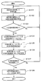
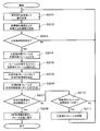
- the flowchart shown in FIG. 2 represents a typical operation of the ultrasonic diagnostic apparatus 100 according to the first embodiment.
- step S101 the ultrasonic transmission / reception processing unit 2 performs transmission control and reception control of the ultrasonic signal, and transmits the ultrasonic wave by driving the probe 1. Further, the reflected ultrasonic wave reflected from the subject carotid artery and received by the probe 1 is subjected to signal processing in the same manner as a general ultrasonic diagnostic apparatus to generate a received signal, and 1 is generated from the generated received signal. Construct reception signals for frames.
- the reception signal in which the frame is configured is sent to the tomographic image processing unit 3 and the end diastole detection unit 4. This operation is performed multiple times at different times. That is, a reception signal for one frame is sequentially formed.
- step S102 the received signal sent from the ultrasonic transmission / reception processing unit 2 is processed by the tomographic image processing unit 3, and a plurality of tomographic images corresponding to frames at different times are constructed.
- step S103 the end diastole detection unit 4 analyzes the received signal sent from the ultrasonic transmission / reception processing unit 2, extracts blood vessel pulsation information, and detects the end diastole timing. If the detected timing is not the end diastole, the process returns to step S101 again to continue the ultrasonic transmission / reception process. When the detected timing is the end diastole, the process proceeds to the next step (step S104).
- this end diastole can be detected using the technique described in Japanese Patent No. 4189405, for example.
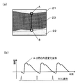
- a technique for detecting this end diastole will be specifically described with reference to FIGS. 3 (a) and 3 (b).
- FIG. 3A schematically shows a cross section along the long axis of the blood vessel
- FIG. 3B shows a measurement point A on the front wall 21 and a measurement point on the rear wall 22 of the blood vessel as shown in FIG.
- a blood vessel inner diameter change waveform which is a change in the distance to B, is shown.
- a blood vessel contracts in accordance with the amount of blood flowing inside and the flow rate. Since the blood flow velocity increases and the blood pressure increases during the systole of the heart, the inner diameter of the blood vessel (distance between the measurement point A and the measurement point B) increases during this systole and the thickness of the blood vessel wall It gets smaller.
- the blood flow rate is slowed and the blood pressure is lowered, so that the inner diameter of the blood vessel in the diastole is reduced and the thickness of the blood vessel wall is increased. That is, since the thickness of the blood vessel wall changes in synchronization with the heartbeat, the IMT value also changes depending on the timing of measurement. Therefore, the inner wall of the blood vessel changes with time due to the pumping of blood from the heart, and a pulse-like waveform as shown in FIG. 3B is observed.
- the ECG R-wave trigger timing (the peak portion of the waveform below FIG. 3B) that is normally used to acquire the end diastole described in Non-Patent Document 1 will be described as a reference.
- FIG. 3 (b) the inner wall thickness of the blood vessel changes due to the blood from the heart.
- the ECG R-wave trigger timing the inner diameter of the blood vessel once decreases, then increases rapidly, and gradually returns to the original diameter.
- the end of diastole is when the inner diameter becomes the smallest before the inner diameter suddenly increases.
- the ECG R-wave trigger timing is considered to be the end diastole in the heart, there is a time difference before the heart beat is transmitted to the carotid artery.
- Deviation occurs with respect to end diastole. Therefore, in the present embodiment, as described above, the timing when the inner diameter becomes the smallest before the inner diameter of the blood vessel suddenly increases is defined as the end diastole. Since the IMT value is measured when the thickness of the blood vessel wall becomes maximum, it is recommended that the ideal timing for performing IMT measurement is the end diastole.
- the configuration for detecting the end diastole using the received signal is shown in order to easily detect the optimum timing of IMT measurement.
- it may be configured to detect the end diastole using a normal ECG. In this case, it is not necessary to send a signal from the ultrasound transmission / reception processing unit 2 in FIG. 1 to the end diastole detection unit 4, and an ECG is connected to the end diastole detection unit 4.
- the measurement target frame selection unit 5 in step S104 based on the end diastole timing detected by the end diastole detection unit 4, A plurality of frames within a predetermined period before and after the end diastole are selected as measurement target frames used for IMT measurement.
- the frame of this period is not acquired at the end diastole timing, but it can be practically used for IMT measurement.
- a plurality of predetermined frames before and after the end diastole may be selected as the measurement target frame.
- the tomographic images are buffered in the memory for the required number of frames and buffered when the end diastole is detected.
- the tomographic image may be selected (the tomographic image buffering means is omitted in FIG. 1).
- the measurable area extraction unit 6 extracts an area that can be used for measurement from the measurement target frame from the measurement target frame.
- the probe 1 preferably captures the vicinity of the center of the short-axis cross section of the blood vessel. Therefore, the measurable region extraction unit 6 extracts a region imaged by passing the ultrasonic beam through the vicinity of the center of the blood vessel from the measurement target portions of each measurement target frame. More specific description will be given below.
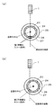
- 4 (a) and 4 (b) are diagrams showing the positional relationship between the probe arranged on the subject and the short-axis cross section of the blood vessel.
- Ultrasonic waves are reflected at boundaries where there is a difference in acoustic impedance, such as tissue boundaries, and the ultrasonic waves are reflected more strongly as they are perpendicular to the boundary surface, and a clear echo signal is obtained. Therefore, as shown in FIG. 4A, when the probe 1 is applied to the subject so that the probe 1 catches the vicinity of the center of the blood vessel (that is, the path of the ultrasonic wave indicated by the broken line portion is the blood vessel. The ultrasonic waves are perpendicular to the lumen inner membrane boundary 26 and the media outer membrane boundary 27 of the blood vessel, and a strong and clear reflection (echo signal) is obtained at both boundaries.
- a strong and clear reflection echo signal
- a clear echo signal is obtained in an area captured by passing an ultrasonic beam near the center of the blood vessel in a measurement target part of the measurement target frame, and unclear in an area captured without passing near the center. Echo signal can be obtained. Therefore, an area where an unclear echo signal is obtained is not used for measurement, and an area where a clear echo signal is obtained is extracted as an area that can be used for measurement. This process is performed in each measurement target frame.
- the measurable region extraction unit 6 first temporarily detects two types of blood vessel boundaries, that is, the lumen inner membrane boundary 26 and the media outer membrane boundary 27 based on the luminance information of the tomographic image. To do. Next, in the tomographic image, as shown in FIG. 16, it is detected whether or not there is a rise in luminance from the blood vessel lumen 23 side to the intima 24 side on the detected acoustic line at the lumen-intima boundary 26 position.
- the measurable area extraction unit 6 determines and extracts a measurable area based on this result.
- the vicinity of the center of the short-axis cross section of the blood vessel in which the above two types of boundaries are clearly depicted is, for example, the distance from the center of the blood vessel cross section to the acoustic line shown in FIG. Say.
- this value is not strictly limited because it depends on the subject, the measurement accuracy of the ultrasonic diagnostic apparatus, measurement conditions, and the like.
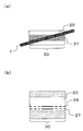
- the probe 1 When performing IMT measurement, it is common to measure using a predetermined length, for example, 1 cm is recommended as the IMT measurement range 30. Therefore, as shown in FIG. 5, the probe 1 is placed on the long-axis section of the carotid artery 20 (perpendicular to the short-axis direction of the blood vessel) so that the probe 1 can catch the vicinity of the center of the blood vessel in the IMT measurement range 30 of 1 cm. (Cross section). Specifically, the probe 1 is arranged so that the longitudinal direction of the probe surface and the long axis direction of the carotid artery 20 are parallel and the scan surface constituted by the ultrasonic beam to be scanned includes the central axis of the carotid artery 20. Arrange for the subject.
- the probe 1 When the probe 1 is arranged along the major axis direction of the carotid artery 20 so as to capture the vicinity 31 of the center of the short axis section of the carotid artery 20 as shown in FIG.
- the probe 1 captures the vicinity 31 of the center of the carotid artery 20 in the range.
- This is an ideal state.
- the tomographic image clearly shows the lumen-intima boundary 26 and the media-media boundary 27 in the entire range of the IMT measurement range 30. Accordingly, since the IMT can be measured in the entire range of the IMT measurement range 30, the entire range of the IMT measurement range 30 is extracted as a measurable region.
- the IMT measurement range 30 is longer than the range in the vicinity of the center 31 of the carotid artery 20, a skilled person who has been sufficiently trained to place the probe 1 at the position shown in FIG. Otherwise it is difficult. Therefore, when the normal operator arranges the probe 1, for example, it becomes as shown in FIG. 7 (a) and FIG. 8 (a).
- the probe 1 is disposed obliquely with respect to the longitudinal direction of the carotid artery 20, and the probe 1 captures the vicinity 31 of the center of the blood vessel only at the center of the IMT measurement range 30. Indicates the state. In this case, in the tomographic image, the lumen intima boundary 26 and the medial epicardial boundary 27 are clearly depicted only at the central portion of the IMT measurement range 30, and these boundaries are unclear at the end. That is, as shown in FIG. 7B, the boundary is clear only in the portion where the probe 1 captures the vicinity 31 of the blood vessel center (the solid line portion between the lumen-intima boundary 26 and the media-media boundary 27).
- the other portions are unclear. Accordingly, at the end of the IMT measurement range 30 in the broken line portion, the lumen-intima boundary 26 and the media-media epicardium boundary 27 are unclear and IMT cannot be measured, and only the central portion of the solid line portion can be measured. Extracted as a region.
- the probe 1 arranged in the long axis direction of the carotid artery 20 is arranged obliquely with respect to the long axis direction of the carotid artery 20 as in FIG. Only the right end of the probe 1 shows a state where the probe 1 captures the vicinity 31 of the center of the carotid artery 20.
- the lumen intima boundary 26 and the medial epicardial boundary 27 are not drawn at the left end, but this is because the probe 1 starts from the vicinity 31 of the center of the blood vessel. It is far off, indicating that these boundaries are not depicted in the tomographic image.
- the right end portion (solid line portion) of the IMT measurement range 30 is extracted as the measurable region at the center portion of the IMT measurement range 30, but the other portions cannot be used for IMT measurement.
- step S106 After extracting the measurable area for each measurement target frame as described above, the process proceeds to step S106, and the measurement processing unit 7 performs IMT measurement processing.
- the measurement processing unit 7 in the IMT measurement range 30 of each measurement target frame uses two types of blood vessels, that is, a lumen-intima boundary 26 and a media-media boundary 27 based on tomographic luminance information and the like. Detect boundaries. At this time, detection processing of these boundaries is performed on a region where the lumen inner membrane boundary 26 and the media outer membrane boundary 27 are clearly depicted in the tomographic image, that is, the measurable region. Alternatively, among the results temporarily detected by the measurable area extraction unit 6, the measurement result of the measurable area portion may be output to the measurement processing unit 7, and the measurement processing unit 7 may perform IMT measurement using the output. . An IMT value is calculated from the distance between the detected lumen-intima boundary 26 and media-epicardium boundary 27.
- the measurement processing unit 7 calculates the IMT value in each measurement target frame, and then combines the measurable area in each measurement target frame to determine the final IMT value. This procedure will be specifically described below.
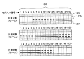
- FIG. 9 shows the detection results of the lumen-intima boundary 26 and the media-endocardium boundary 27 on the tomogram in three measurement target frames acquired within a predetermined period before and after the end diastole.
- the “segment number” shown in FIG. 9 is defined as the position or order of a segment that is a reference unit (length) for determining whether or not the measurable area extraction unit 6 is a measurable area in the IMT measurement range 30. For example, when the length of the IMT measurement range 30 is 1 cm and the IMT measurement range 30 is divided into 20 segments, the length of each segment is 0.5 mm. The length of the segment can be determined according to the resolution of the probe 1 to be used and the required IMT measurement accuracy.
- the segments in which the lumen inner membrane boundary 26 and the media outer membrane boundary 27 are drawn with solid lines represent segments in which these boundaries are clearly drawn.
- the measurable region extraction unit 6 This is an area extracted as a measurable area.
- a segment in which the lumen-intima boundary 26 and the media-endocardium boundary 27 are drawn with broken lines indicates that these boundaries are unclear segments, and those segments that are not drawn are detected by these boundaries. Represents a segment that could not be done.
- These segments are areas that were not extracted as measurable areas by the measurable area extracting unit 6. As shown in FIG.
- the reason for becoming a measurable region or a non-measurable region is that the carotid artery This is because, even if the movement of the internal tissue included and the operator fixes the probe 1, subtle blurring actually occurs.
- the lumen inner membrane boundary 26 and the media outer membrane boundary 27 are clearly depicted only in the measurement target frame 3. Therefore, the IMT value is measured from the tomographic image of the measurement target frame 3 in the range of these segments.
- the lumen inner membrane boundary 26 and the media outer membrane boundary 27 are clearly depicted in both the measurement target frames 2 and 3. Therefore, in these segments, the IMT value is measured from the tomographic images of the measurement target frames 2 and 3.
- the detected IMT values of the lumen intima boundary and the medial epicardial boundary are calculated for each of the frames, and the average of the IMT values may be obtained for each segment.
- a frame in which the lumen intima boundary 26 and the medial epicardial boundary 27 are more clearly depicted is determined for each segment, and the lumen intima boundary 26 and the medial epicardial boundary are determined using the determined frame. 27 detection and IMT value calculation may be performed.
- the IMT value is calculated from the tomographic image of the measurement target frame 2.
- the IMT value is calculated from the tomographic images of the measurement target frames 1 and 2.
- the IMT value is calculated from the tomographic image of the measurement target frame 1.
- the measurement target frames 1 to 3 have a measurable region that is only part of the IMT measurement range 30. In other words, it is possible to measure the IMT value over substantially the entire IMT measurement range 30. If the IMT value is measured for each segment and the maximum value in all segments is determined, maxIMT is obtained. Moreover, meanIMT is calculated
- the measurement processing unit 7 measures the IMT values in the IMT measurement range 30 of the entire range by combining the measurable regions extracted in the respective measurement target frames by the measurable region extraction unit 6. showed that.
- the IMT values in the IMT measurement range 30 of the entire range may not be measured.
- the IMT measurement may be partially performed using only the measurable region extracted from the IMT measurement range 30. At this time, the greater the measurable area, that is, the more measurable segments, the more accurate maxIMT and meanIMT that are measured.
- the probe 1 cannot be properly held and the region (segment) where the probe 1 captures the vicinity 31 of the blood vessel changes, a plurality of measurement target frames are combined.
- the IMT value can be appropriately measured. Therefore, it is possible to easily measure the IMT value even if it is not an expert.
- the IMT value can be measured within a predetermined range within the IMT measurement range 30, the maxIMT and meanIMT obtained from this are considered to be sufficiently accurate, the IMT measurement value is confirmed, and the measurement is completed. It can also be controlled. Hereinafter, this control will be described in detail with reference to FIG.
- the control unit 8 uses each measurement target frame used in the IMT measurement process of the measurement processing unit 7 in step S107. It is determined whether or not the total of the measurable areas occupies a predetermined ratio in the IMT measurement range 30. At this time, if the predetermined ratio is not satisfied, the process returns to step S101 to continue the measurement. On the other hand, when the total of the measurable area is equal to or greater than the predetermined ratio, the process proceeds to step S108, and the control unit 8 determines the IMT measurement value. At that time, by automatically shifting the apparatus to the freeze state, the operator can confirm on the display 10 a tomographic image in which the result of the IMT measurement value is confirmed.
- the total ratio of the measurable area necessary for determining the IMT measurement value may be 100% (the entire area of the IMT measurement range 30 (for example, 1 cm), or a constant ratio smaller than 1. If this ratio is increased, the accuracy of the IMT value is improved, and if the ratio is decreased, IMT measurement can be performed even if it is slightly deviated from an appropriate position, so that the operability is improved. If 75% of the range 30, the total measurable area is 7.5 mm or more, the IMT measurement value is determined.
- the above-mentioned 1 cm wide IMT measurement range 30 is divided into 20 segments of 0.5 mm each. In the example of dividing into two, if there are 15 or more measurable segments, the IMT measurement value is determined.
- the measurable areas in the same area overlap in a predetermined number or more of measurement target frames, and the ratio of the overlapping measurable areas is a predetermined value in the IMT measurement range 30. If it is above, it is also possible to determine the IMT measurement value and control to complete the measurement.
- IMT measurement is possible with only one frame of measurement target frame 3
- IMT measurement is possible in two frames of measurement target frames 2 and 3
- measurement is performed in segments 8 and 9
- IMT measurement is possible in all three frames of target frames 1 to 3
- IMT measurement is possible in two frames of measurement target frames 1 and 2 in segments 10 to 18, and IMT measurement is possible in only one frame of measurement target frame 1 in segments 19 and 20 It is.
- 16 segments of segments 3 to 18 that can be measured with two or more measurement target frames are 75% or more (15 or more segments) of the IMT measurement range 30. For this reason, the control unit 8 determines the IMT measurement value and completes the measurement.
- the image synthesizing unit 9 synthesizes the IMT measurement value measured by the measurement processing unit 7 and the tomographic image constructed by the tomographic image processing unit 3 to display the display 10. By outputting to the operator, the operator can check the diagnostic image and the measurement result.
- FIG. 11 is a block diagram showing Embodiment 2 of the ultrasonic diagnostic apparatus of the present invention. Blocks having the same functions as those in Embodiment 1 are given the same numbers, and descriptions thereof are omitted. Further, the present embodiment will be described by taking IMT measurement of the carotid artery as an example.
- the measurement target frame selection unit 50 includes a plurality of measurement target frames to be subjected to IMT measurement among a plurality of tomographic images generated by the tomographic image processing unit 3. Select. However, the measurement target frame selection unit 5 of the first embodiment selects a plurality of frames included in a predetermined period before and after the end diastole detected by the end diastole detection unit 4 as the measurement target frames. On the other hand, the measurement target frame selection unit 50 according to the present embodiment selects a frame obtained at each end diastole timing detected during one cardiac cycle by the end diastole detection unit 4 as a measurement target frame.
- the frame recording unit 11 records the tomographic image of the end-diastolic frame selected by the measurement target frame selection unit 50 and reads a plurality of recorded tomographic images to measure the region that can be measured as a measurement target frame 6. To hand.
- the control unit 80 controls each block as well as the control unit 8 of the first embodiment, and confirms the measurement result of the measurement processing unit 7 as an IMT measurement value. It is also possible to perform control so that when the operator confirms the IMT measurement value as the IMT measurement value, it automatically shifts to the frozen state so that the operator can confirm the tomographic image in which the result of the IMT measurement value is confirmed. .
- the difference from the control unit 8 of the first embodiment is that control is performed to discard a frame (tomographic image) recorded in the frame recording unit 11 when a predetermined condition is met.
- Step S203 returns to step S201 and continues the transmission / reception process of ultrasonic waves when the timing detected by the end diastole detection unit 4 is not the end diastole, as in step S103.
- the process proceeds to the next step S204.
- step S209 the frame recording unit 11 records a tomographic image of the end diastole frame selected by the measurement target frame selection unit 50. Then, a tomographic image of an end-diastolic frame corresponding to a predetermined heart rate recorded in the frame recording unit 11 (for example, 3 frames when the predetermined heart rate is 3 heartbeats) is read and measured as a measurement target frame. Output to the possible area extraction unit 6.
- the predetermined number of frames for example, 3 frames
- only the recorded frames may be used as measurement target frames.
- the operations of the measurable area extraction unit 6 and the measurement processing unit 7 are the same as those in the first embodiment, and the processes in steps S205 and S206 are the same as steps S105 and S106 in the first embodiment, respectively.
- the measurement target frame is the end-diastolic frame for a plurality of heartbeats read from the frame recording unit 11.
- step S207 the control unit 80 performs the same processing as in the control unit 8 in step S107 of the first embodiment, and the total of the measurable area of the measurement target frame used in the IMT measurement process of the measurement processing unit 7 is It is determined whether or not it occupies a predetermined area or more in the IMT measurement range 30. When this condition is satisfied, the control unit 80 determines the IMT measurement value in step S208 as in the control unit 8 in step S108 of the first embodiment. Further, at this time, the apparatus can be controlled to automatically shift to the frozen state.
- the frame recorded in the frame recording unit 11 can be discarded.
- the fact that there is no measurable region means that the position of the probe 1 has completely shifted from the vicinity 31 of the center of the blood vessel, and it can be considered that the measurement has been interrupted. Therefore, the previous frame is discarded so as not to be used for the subsequent measurement.
- the frame recorded in the frame recording unit 11 can be discarded (from the operation unit and the operation unit to the control unit).
- the path to 80 is omitted in FIG. 11).
- parameters related to measurement area change and ultrasonic transmission / reception in the ultrasonic transmission / reception processing unit 2 (for example, scanning line density, presence / absence of parallel reception or number of parallel receptions, transmission frequency, transmission power, transmission interval) Change, and parameters (gain, dynamic range, presence / absence of filter processing or characteristics) relating to tomogram construction in the tomogram processor 3.
- the frame recorded in the frame recording unit 11 can be discarded (from the movement detection unit and the detection unit of the probe 1).
- the path to the control unit 80 is omitted in FIG. 11).
- a means for detecting the movement of the probe 1 there are a method for determining from a change in a tomographic image, a method for providing a sensor such as an angle sensor to the probe 1, and the like.
- the fact that the probe 1 has moved greatly means that the measurement site is different from that before that, and the previous frame is discarded so that it will not be used for the subsequent measurement.
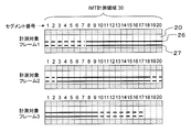
- FIG. 13 shows the result of rendering the lumen intima boundary and the medial epicardial boundary in each tomogram of the end-diastolic frame for 6 heartbeats selected as the measurement target frame (end-diastolic frames 1 to 6).
- An example is shown.
- the frame before the end diastole frame 1 is not considered.
- the meanings of the segments in FIG. 13, solid lines, and dotted lines are the same as those in FIG. 9 in the first embodiment.
- the determination condition in step S207 is that the IMT measurement value is determined when IMT measurement is possible in the entire range of the IMT measurement range 30 (all 20 segments) in any one of the measurement target frames, and the measurement is completed. Shall.
- the measurement target frame selecting unit 50 selects the end diastole frame 1 and the frame recording unit 11 records the data of the frame. Then, the end diastole frame 1 is read from the frame recording unit 11 and output to the measurable region extraction unit 6.
- the measurable area extracting unit 6 extracts the segments 10 to 20 as measurable areas, and the measurement processing unit 7 measures the IMT using the extracted segments of the measurable area.
- the control unit 80 determines whether the measurable area is equal to or greater than a predetermined ratio. In the end diastole frame 1 alone, IMT measurement is possible only in 11 segments, so the IMT measurement value is not yet determined.
- the measurement target frame selection unit 50 selects the end diastole frame 2 and the frame recording unit 11 records the data of the frame.
- the end diastole frames 1 and 2 are read from the frame recording unit 11 and output to the measurable region extraction unit 6. Similar to the first heartbeat, the measurable area extraction unit 6 and the measurement processing unit 7 perform the above-described operation, and the control unit 80 determines whether the measurable area is equal to or greater than a predetermined ratio. Even if the end diastole frames 1 and 2 are combined, since the IMT measurement is possible only in 13 segments of the segments 8 to 20, the IMT measurement value is not yet determined.
- the measurement target frame selection unit 50 selects the end diastole frame 3 and the frame recording unit 11 records the frame data. Then, end-diastolic frames 1 to 3 are read from the frame recording unit 11.
- the measurable area extraction unit 6 and the measurement processing unit 7 perform the above-described operation. As shown in FIG. 13, there is no measurable segment in the end diastole frame 3. Therefore, as described above, the control unit 80 determines that the conditions for discarding the frames recorded in the frame recording unit 11 are met, and causes the frame recording unit 11 to discard the data of the end-diastolic frames 1 to 3. Instruct. As a result, even when the end-diastolic frames 1 to 3 are combined, the IMT measurement value is not yet determined, and the measurement is repeated (steps S210, S211 and S201).
- the measurement target frame selection unit 50 selects the end diastole frame 4 and the frame data is recorded in the frame recording unit 11. Since the previous frame is discarded in the frame recording unit 11, only the end diastole frame 4 is read from the frame recording unit 11. Thereafter, similar processing is performed, and the control unit 80 determines whether or not the measurable area is equal to or greater than a predetermined ratio. Since the IMT measurement is possible only in the six segments 15 to 20 in the end diastole frame 4, the control unit 80 does not yet determine the IMT measurement value.
- the measurement target frame selection unit 50 selects the end diastole frame 5 and the frame data is recorded in the frame recording unit 11. Then, end-diastolic frames 4 and 5 are read from the frame recording unit 11. Even if the end-diastolic end frames 4 and 5 are combined, the IMT measurement is possible only in the 14 segments 7 to 20, so the control unit 80 does not yet determine the IMT measurement value.
- the measurement target frame selecting unit 50 selects the end diastole frame 6 and the frame recording unit 11 records the frame data. Then, end-diastolic frames 4 to 6 are read from the frame recording unit 11.
- the measurable area extraction unit 6 and the measurement processing unit 7 execute the above-described operation, and the IMT value is measured.
- the control unit 80 determines that the measurable area is equal to or greater than a predetermined ratio, and the IMT measured by the measurement processing unit 7 The value is confirmed as the IMT measurement value, thereby completing the measurement.
- the apparatus can be controlled to automatically shift to the frozen state.
- the end-diastolic frame of one heartbeat does not occupy a sufficient proportion of the IMT measurement range 30
- the end-diastolic ends of a plurality of heartbeats If the measurable area satisfies the sufficient range of the IMT measurement range 30 by combining the frames, the IMT can be appropriately measured. Therefore, IMT can be easily measured.
- the measurement target frame selection unit 50 of this embodiment selects a measurement target frame from a plurality of frames (for example, three frames) before and after the end of diastole, like the measurement target frame selection unit 5 of the first embodiment. May be.
- the frame recording unit 11 records the selected three frames at a time.
- the measurable area extraction unit 6, the measurement processing unit 7, and the control unit 8 perform the above-described processing using three measurement target frames per heartbeat.
- control unit 80 determines to discard the frame recorded in the frame recording unit 11 when there is no measurable area in any of the three measurement target frames of one heartbeat. May be. Alternatively, when no measurable area exists in at least one or two of the three measurement target frames of one heartbeat, it may be determined to discard the frame recorded in the frame recording unit 11.
- the ultrasonic diagnostic apparatus of the present embodiment can be used for various measurements other than the IMT measurement of the carotid artery, as in the first embodiment.
- FIG. 14 is a block diagram showing Embodiment 3 of the ultrasonic diagnostic apparatus according to the present invention. Blocks having the same functions as those in Embodiment 1 are given the same numbers, and descriptions thereof are omitted. In the third embodiment, IMT measurement will be described as an example.
- Embodiment 1 performs IMT measurement from a tomogram, but this embodiment differs from Embodiment 1 in that IMT measurement is performed from a received signal. Further, in the present embodiment, IMT measurement is performed from the received signal itself, but it may be configured to perform IMT measurement from information (for example, luminance information) for constructing a tomographic image generated from the received signal.
- information for example, luminance information
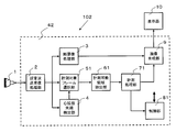
- the ultrasonic diagnostic apparatus 102 includes a controller 42.
- the controller 42 includes an ultrasonic transmission / reception processor 2, a tomogram processor 3, a diastole end detector 4, a measurement target frame selector 51, a measurable area extractor 61, a measurement processor 71, a controller 81, and an image.
- a synthesis unit 9 is included.
- the ultrasonic transmission / reception processing unit 2 adds the generated reception signal to the tomographic image processing unit 3 and the end diastole detection unit 4 and outputs it to the measurement target frame selection unit 51.
- the measurement target frame selection unit 51 selects at least two or more measurement target frames to be subjected to IMT measurement from the reception signals of the plurality of frames generated by the ultrasonic transmission / reception processing unit 2.
- a plurality of frames including the end diastole detected by the end diastole detection unit 4 and included in a predetermined period before and after the end diastole are selected as measurement target frames. .
- the measurable area extraction unit 61 extracts, for each measurement target frame, an area that can be sufficiently measured from the measurement target parts in each measurement target frame. To do.
- the frame data to be handled is not the tomographic luminance information but the received signal itself. For this reason, the measurable area to be extracted is not an area on the tomographic image, but a portion that can be measured in the received signal group constituting the frame.
- the measurement processing unit 71 performs a predetermined measurement process on the area that can be measured and extracted by the measurable area extraction unit 61 as in the measurement processing unit 7 of the first embodiment.
- the data of each frame is measured using the received signal itself, not the luminance information of the tomographic image.
- the measurable area extracting unit 61 and the measurement processing unit 71 perform the above-described processing using the amplitude information of the reception signal that constitutes the frame instead of the luminance information of the tomographic image. Thereby, the same processing as that of the measurable area extraction unit 6 and the measurement processing unit 7 of the first embodiment is performed. Specifically, in the process of extracting the measurable region, instead of determining whether the lumen-intima boundary 26 and the media-media boundary 27 are clearly depicted in the tomographic image, the lumen is displayed on the received signal. It is determined whether the change in amplitude corresponding to the intima boundary 26 and the intima-exterior boundary 27 appears clearly.
- the measurable region that is, the received signal group constituting the frame, from the portion where the measurement process can be performed, from the lumen intima boundary 26 and the media outer membrane Two types of blood vessel boundaries with the boundary 27 are detected.
- the control unit 81 controls each block as well as the control unit 8 of the first embodiment, and confirms the measurement result of the measurement processing unit 71 as an IMT measurement value. It is also possible to perform control so that when the operator confirms the IMT measurement value as the IMT measurement value, it automatically shifts to the frozen state so that the operator can confirm the tomographic image in which the result of the IMT measurement value is confirmed. .
- the operation of the ultrasonic diagnostic apparatus 102 shown in the third embodiment is the same as the flowchart shown in FIG. 2 of the first embodiment except that the amplitude information of the received signal constituting the frame is used instead of the luminance information of the tomographic image described above.
- the operation is the same as described with reference to FIG.
- the measurable area is extracted and measured using the amplitude information of the received signal instead of the tomogram. For this reason, unlike Embodiment 1, it can process without depending on the setting and parameter at the time of constructing a tomographic image.
- the ultrasonic diagnostic apparatus can be used for various measurements other than the IMT measurement of the carotid artery.
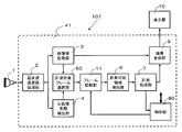
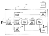
- FIG. 15 is a block diagram of an ultrasonic diagnostic apparatus according to Embodiment 4 of the present invention. Blocks having the same functions as those in Embodiments 1 to 3 are given the same numbers, and descriptions thereof are omitted. Also in the present embodiment, description will be made by taking IMT measurement of the carotid artery as an example.
- the present embodiment is different from the first embodiment in that IMT measurement is performed from a received signal.
- IMT measurement is performed from the received signal itself.
- IMT measurement is performed from information (for example, luminance information) for constructing a tomographic image generated from the received signal. Needless to say, it may be.
- the ultrasonic diagnostic apparatus 103 includes a controller 43.
- the controller 43 includes an ultrasonic transmission / reception processing unit 2, a tomographic image processing unit 3, a diastole end detection unit 4, a measurement target frame selection unit 52, a measurable region extraction unit 61, a measurement processing unit 71, a control unit 82, and an image.
- a synthesis unit 9 is included.
- the ultrasonic transmission / reception processing unit 2 outputs the generated reception signal to the measurement target frame selection unit 52 in addition to the tomographic image processing unit 3 and the end diastole detection unit 4.
- the measurement target frame selection unit 52 selects two or more measurement target frames to be subjected to IMT measurement from among a plurality of reception signals generated by the ultrasonic transmission / reception processing unit 2.
- the frame of the end diastole timing detected by the end diastole detection unit 4 is selected as the measurement target frame.
- the frame recording unit 12 records the reception signal of the end diastole frame selected by the measurement target frame selection unit 52 and reads the reception signals of a plurality of recorded frames to extract a measurable region as the measurement target frame. To the unit 61.
- the operation of the frame recording unit 12 is the same as that of the frame recording unit 11 of the second embodiment, except that the reception signal constituting the frame is recorded instead of the luminance information of the tomographic image.
- the operations of the measurable area extraction unit 61 and the measurement processing unit 71 are the same as those in the third embodiment.
- the control unit 82 controls each block as well as the control unit 80 of the second embodiment, and determines the measurement result of the measurement processing unit 71 as the IMT measurement value. In addition, when a predetermined condition is met, control is performed to discard the frame (received signal) recorded in the frame recording unit 12. It is also possible to perform control so that when the operator confirms the IMT measurement value as the IMT measurement value, it automatically shifts to the freeze state so that the operator can confirm the tomographic image in which the result of the IMT measurement value is confirmed.
- the operation of the ultrasound diagnostic apparatus 103 shown in the fourth embodiment is the same as the flowchart shown in FIG. The operation is the same as described above.
- the measurable area is extracted and measured using the amplitude information of the received signal instead of the tomogram. For this reason, unlike Embodiment 2, it can process without depending on the setting and parameter at the time of constructing a tomographic image.
- the ultrasonic diagnostic apparatus can be used for various measurements other than the IMT measurement of the carotid artery.
- various techniques in the body of the subject such as IMT measurement, blood vessel diameter measurement, fetal measurement, and the like can be performed easily and accurately even by non-experts. Can be measured.
- the measurement process is performed by extracting each measurable region based on the reception signals or tomographic images of a plurality of frames acquired at a plurality of times and combining them.
- the above-described measurement can be performed without using a complicated probe such as a 3D probe or a 4D probe. That is, accurate measurement can be realized even by using an array probe in which transducers are arranged in a one-dimensional direction, which is a general simple probe.
- the ultrasonic diagnostic apparatus even if the probe is displaced from the correct position of the measurement target portion with respect to the subject, the exact position of the probe is corrected to correct the deviation. It is not necessary to make adjustments, and appropriate measurement processing can be performed if the measurable region satisfies a sufficient range of the measurement target region by combining a plurality of measurement target frames.
Landscapes
- Health & Medical Sciences (AREA)
- Life Sciences & Earth Sciences (AREA)
- Engineering & Computer Science (AREA)
- Heart & Thoracic Surgery (AREA)
- Molecular Biology (AREA)
- Nuclear Medicine, Radiotherapy & Molecular Imaging (AREA)
- Pathology (AREA)
- Radiology & Medical Imaging (AREA)
- Physics & Mathematics (AREA)
- Biomedical Technology (AREA)
- Veterinary Medicine (AREA)
- Medical Informatics (AREA)
- Biophysics (AREA)
- Surgery (AREA)
- Animal Behavior & Ethology (AREA)
- General Health & Medical Sciences (AREA)
- Public Health (AREA)
- Physiology (AREA)
- Computer Vision & Pattern Recognition (AREA)
- Vascular Medicine (AREA)
- Cardiology (AREA)
- Ultra Sonic Daignosis Equipment (AREA)
Priority Applications (4)
| Application Number | Priority Date | Filing Date | Title |
|---|---|---|---|
| CN201280004506.9A CN103298413B (zh) | 2011-06-13 | 2012-06-07 | 超声波诊断装置以及利用该超声波诊断装置的超声波测量方法 |
| EP12800539.4A EP2719334A4 (en) | 2011-06-13 | 2012-06-07 | ULTRASONIC DIAGNOSIS DEVICE AND ULTRASONIC MEASURING PROCESS THEREWITH |
| JP2013520422A JP5975027B2 (ja) | 2011-06-13 | 2012-06-07 | 超音波診断装置およびそれを用いた超音波計測方法 |
| US14/000,702 US9770227B2 (en) | 2011-06-13 | 2012-06-07 | Ultrasound diagnostic apparatus and ultrasound measurement method using same |
Applications Claiming Priority (2)
| Application Number | Priority Date | Filing Date | Title |
|---|---|---|---|
| JP2011-130873 | 2011-06-13 | ||
| JP2011130873 | 2011-06-13 |
Publications (1)
| Publication Number | Publication Date |
|---|---|
| WO2012172756A1 true WO2012172756A1 (ja) | 2012-12-20 |
Family
ID=47356766
Family Applications (1)
| Application Number | Title | Priority Date | Filing Date |
|---|---|---|---|
| PCT/JP2012/003723 WO2012172756A1 (ja) | 2011-06-13 | 2012-06-07 | 超音波診断装置およびそれを用いた超音波計測方法 |
Country Status (5)
| Country | Link |
|---|---|
| US (1) | US9770227B2 (zh) |
| EP (1) | EP2719334A4 (zh) |
| JP (1) | JP5975027B2 (zh) |
| CN (1) | CN103298413B (zh) |
| WO (1) | WO2012172756A1 (zh) |
Cited By (1)
| Publication number | Priority date | Publication date | Assignee | Title |
|---|---|---|---|---|
| WO2014129203A1 (ja) * | 2013-02-25 | 2014-08-28 | コニカミノルタ株式会社 | 超音波診断装置および超音波診断装置の制御方法 |
Families Citing this family (5)
| Publication number | Priority date | Publication date | Assignee | Title |
|---|---|---|---|---|
| KR101797042B1 (ko) * | 2015-05-15 | 2017-11-13 | 삼성전자주식회사 | 의료 영상 합성 방법 및 장치 |
| US11771399B2 (en) | 2018-02-07 | 2023-10-03 | Atherosys, Inc. | Apparatus and method to guide ultrasound acquisition of the peripheral arteries in the transverse plane |
| US20190246910A1 (en) * | 2018-02-13 | 2019-08-15 | National Chiao Tung University | Imaging-Type Heart Rate Monitoring Device and Method Thereof |
| JP6856816B2 (ja) * | 2018-02-23 | 2021-04-14 | 富士フイルム株式会社 | 超音波診断装置および超音波診断装置の制御方法 |
| CN112603374A (zh) * | 2020-12-24 | 2021-04-06 | 无锡祥生医疗科技股份有限公司 | 颈动脉超声影像处理方法、装置、存储介质及超声设备 |
Citations (5)
| Publication number | Priority date | Publication date | Assignee | Title |
|---|---|---|---|---|
| JP2005000390A (ja) * | 2003-06-11 | 2005-01-06 | Shimadzu Corp | 超音波診断装置 |
| JP2007159920A (ja) * | 2005-12-15 | 2007-06-28 | Matsushita Electric Ind Co Ltd | 超音波診断装置 |
| JP2008168016A (ja) | 2007-01-15 | 2008-07-24 | Fujifilm Corp | 超音波診断装置、imt計測方法及びimt計測プログラム |
| JP4189405B2 (ja) | 2003-05-20 | 2008-12-03 | パナソニック株式会社 | 超音波診断装置 |
| JP2010022565A (ja) | 2008-07-18 | 2010-02-04 | Fujifilm Corp | 超音波診断装置 |
Family Cites Families (3)
| Publication number | Priority date | Publication date | Assignee | Title |
|---|---|---|---|---|
| US7074187B2 (en) * | 2002-12-13 | 2006-07-11 | Selzer Robert H | System and method for improving ultrasound image acquisition and replication for repeatable measurements of vascular structures |
| US20050267365A1 (en) | 2004-06-01 | 2005-12-01 | Alexander Sokulin | Method and apparatus for measuring anatomic structures |
| JP5346440B2 (ja) | 2007-02-15 | 2013-11-20 | 富士フイルム株式会社 | 超音波診断装置及びデータ計測プログラム |
-
2012
- 2012-06-07 JP JP2013520422A patent/JP5975027B2/ja active Active
- 2012-06-07 CN CN201280004506.9A patent/CN103298413B/zh not_active Expired - Fee Related
- 2012-06-07 EP EP12800539.4A patent/EP2719334A4/en not_active Withdrawn
- 2012-06-07 WO PCT/JP2012/003723 patent/WO2012172756A1/ja active Application Filing
- 2012-06-07 US US14/000,702 patent/US9770227B2/en active Active
Patent Citations (5)
| Publication number | Priority date | Publication date | Assignee | Title |
|---|---|---|---|---|
| JP4189405B2 (ja) | 2003-05-20 | 2008-12-03 | パナソニック株式会社 | 超音波診断装置 |
| JP2005000390A (ja) * | 2003-06-11 | 2005-01-06 | Shimadzu Corp | 超音波診断装置 |
| JP2007159920A (ja) * | 2005-12-15 | 2007-06-28 | Matsushita Electric Ind Co Ltd | 超音波診断装置 |
| JP2008168016A (ja) | 2007-01-15 | 2008-07-24 | Fujifilm Corp | 超音波診断装置、imt計測方法及びimt計測プログラム |
| JP2010022565A (ja) | 2008-07-18 | 2010-02-04 | Fujifilm Corp | 超音波診断装置 |
Non-Patent Citations (2)
| Title |
|---|
| JOURNAL OF THE AMERICAN SOCIETY OF ECHOCARDIOGRAPHY, February 2008 (2008-02-01), pages 93 - 111 |
| See also references of EP2719334A4 |
Cited By (2)
| Publication number | Priority date | Publication date | Assignee | Title |
|---|---|---|---|---|
| WO2014129203A1 (ja) * | 2013-02-25 | 2014-08-28 | コニカミノルタ株式会社 | 超音波診断装置および超音波診断装置の制御方法 |
| JPWO2014129203A1 (ja) * | 2013-02-25 | 2017-02-02 | コニカミノルタ株式会社 | 超音波診断装置および超音波診断装置の制御方法 |
Also Published As
| Publication number | Publication date |
|---|---|
| US20130331700A1 (en) | 2013-12-12 |
| EP2719334A1 (en) | 2014-04-16 |
| US9770227B2 (en) | 2017-09-26 |
| CN103298413B (zh) | 2015-07-29 |
| CN103298413A (zh) | 2013-09-11 |
| JP5975027B2 (ja) | 2016-08-23 |
| JPWO2012172756A1 (ja) | 2015-02-23 |
| EP2719334A4 (en) | 2014-11-12 |
Similar Documents
| Publication | Publication Date | Title |
|---|---|---|
| JP5754379B2 (ja) | 超音波診断装置および内中膜複合体厚の測定方法 | |
| JP5501999B2 (ja) | 超音波診断装置および弾性指標信頼性判定方法 | |
| JP5928342B2 (ja) | 超音波診断装置および超音波診断装置の制御方法 | |
| JP4864547B2 (ja) | 超音波診断装置およびその制御処理プログラム | |
| JP5158880B2 (ja) | 超音波診断装置 | |
| JP5975027B2 (ja) | 超音波診断装置およびそれを用いた超音波計測方法 | |
| JP2005342006A (ja) | 超音波診断装置、超音波画像処理装置、及び超音波信号処理プログラム | |
| WO2006082966A1 (ja) | 超音波診断装置 | |
| JP5292440B2 (ja) | 超音波診断装置 | |
| JP5649519B2 (ja) | 超音波診断装置 | |
| JP5384919B2 (ja) | 超音波診断装置 | |
| JP5438722B2 (ja) | 超音波診断装置 | |
| JP6687336B2 (ja) | 超音波診断装置及び制御プログラム | |
| JP5400095B2 (ja) | 超音波診断装置 | |
| JP2010269018A (ja) | 超音波診断装置 | |
| JP5588928B2 (ja) | 超音波診断装置 | |
| JP4921816B2 (ja) | 超音波診断装置及びその制御プログラム | |
| JP2008104641A (ja) | 超音波診断装置、心拍同期信号生成装置及び心拍同期信号生成方法 | |
| JP5462474B2 (ja) | 超音波診断装置 | |
| JP5826984B2 (ja) | 超音波診断装置、心拍同期信号生成装置及び心拍同期信号生成方法 | |
| JP4745455B2 (ja) | 超音波診断装置、超音波画像処理装置、及び超音波信号処理プログラム | |
| JP2012249844A (ja) | 超音波診断装置 | |
| JP4691185B2 (ja) | 超音波画像表示装置 | |
| JP2006166955A (ja) | 超音波診断装置 | |
| JP2007014541A (ja) | 超音波診断装置 |
Legal Events
| Date | Code | Title | Description |
|---|---|---|---|
| 121 | Ep: the epo has been informed by wipo that ep was designated in this application |
Ref document number: 12800539 Country of ref document: EP Kind code of ref document: A1 |
|
| WWE | Wipo information: entry into national phase |
Ref document number: 14000702 Country of ref document: US |
|
| WWE | Wipo information: entry into national phase |
Ref document number: 2012800539 Country of ref document: EP |
|
| ENP | Entry into the national phase |
Ref document number: 2013520422 Country of ref document: JP Kind code of ref document: A |
|
| NENP | Non-entry into the national phase |
Ref country code: DE |