WO2012172734A1 - 引き戸の開放補助装置 - Google Patents
引き戸の開放補助装置 Download PDFInfo
- Publication number
- WO2012172734A1 WO2012172734A1 PCT/JP2012/003415 JP2012003415W WO2012172734A1 WO 2012172734 A1 WO2012172734 A1 WO 2012172734A1 JP 2012003415 W JP2012003415 W JP 2012003415W WO 2012172734 A1 WO2012172734 A1 WO 2012172734A1
- Authority
- WO
- WIPO (PCT)
- Prior art keywords
- sliding door
- opening
- pressed
- door
- pressing member
- Prior art date
- Legal status (The legal status is an assumption and is not a legal conclusion. Google has not performed a legal analysis and makes no representation as to the accuracy of the status listed.)
- Ceased
Links
Images






Classifications
-
- E—FIXED CONSTRUCTIONS
- E05—LOCKS; KEYS; WINDOW OR DOOR FITTINGS; SAFES
- E05B—LOCKS; ACCESSORIES THEREFOR; HANDCUFFS
- E05B17/00—Accessories in connection with locks
- E05B17/0025—Devices for forcing the wing firmly against its seat or to initiate the opening of the wing
- E05B17/0033—Devices for forcing the wing firmly against its seat or to initiate the opening of the wing for opening only
-
- E—FIXED CONSTRUCTIONS
- E05—LOCKS; KEYS; WINDOW OR DOOR FITTINGS; SAFES
- E05B—LOCKS; ACCESSORIES THEREFOR; HANDCUFFS
- E05B65/00—Locks or fastenings for special use
- E05B65/08—Locks or fastenings for special use for sliding wings
- E05B65/0835—Locks or fastenings for special use for sliding wings the bolts pivoting about an axis parallel to the wings
- E05B65/0841—Locks or fastenings for special use for sliding wings the bolts pivoting about an axis parallel to the wings and parallel to the sliding direction of the wings
-
- E—FIXED CONSTRUCTIONS
- E05—LOCKS; KEYS; WINDOW OR DOOR FITTINGS; SAFES
- E05C—BOLTS OR FASTENING DEVICES FOR WINGS, SPECIALLY FOR DOORS OR WINDOWS
- E05C3/00—Fastening devices with bolts moving pivotally or rotatively
- E05C3/02—Fastening devices with bolts moving pivotally or rotatively without latching action
- E05C3/04—Fastening devices with bolts moving pivotally or rotatively without latching action with operating handle or equivalent member rigid with the bolt
- E05C3/041—Fastening devices with bolts moving pivotally or rotatively without latching action with operating handle or equivalent member rigid with the bolt rotating about an axis perpendicular to the surface on which the fastener is mounted
- E05C3/046—Fastening devices with bolts moving pivotally or rotatively without latching action with operating handle or equivalent member rigid with the bolt rotating about an axis perpendicular to the surface on which the fastener is mounted in the form of a crescent-shaped cam
Definitions
- the present invention relates to a sliding door opening auxiliary device attached to a window or an entrance of a building or the like.
- an opening assistance device has been developed to assist the operator in initial operation when such a sliding door is opened.
- sliding doors that can be opened and closed in a square frame formed in the opening of a building so that they can be opened and closed in a sliding manner or in a single-drawing manner, they are provided on the door toe to help reduce the initial operation at the time of opening.
- an opening / closing assist device that performs unlocking of a hook lock provided as a door-end lock on a door-end collar in conjunction with an opening operation of the opening / closing assist device (see Patent Document 1).
- the opening assist device is provided on the door-end side (door-end fence) of the sliding door, and the operation handle is arranged so as to protrude from the main surface of the sliding door. . Therefore, when increasing the overlap of the two sliding doors to maximize the opening, the opening assisting device including the handle hits the door butt (summing bowl) of the other sliding doors and completely overlaps the two sliding doors. There is a problem that it cannot be combined. That is, there is a problem that the opening assist device limits the opening / closing range of the sliding door. This problem occurs when the handle abuts against the opening edge of the door pocket even when the sliding door is moved in and out of the door pocket.
- This invention is made in view of the above problem, and makes it a subject that the opening assistance apparatus of a sliding door does not restrict
- the present invention provides an opening assist device (1, 100) for assisting an initial operation when the sliding door (3) is opened from the closed position, wherein the sliding door is in the closed position.
- the pressing member is arranged apart from the sliding door so as not to come into contact with the sliding door when the sliding door opens and closes at the initial position.
- the operating member and the pressing member are supported by the support member, and the pressing member acting on the door bottom does not contact the sliding door that opens and closes at the initial position. There is no regulation.
- the door butt portion includes a sump that protrudes toward the support member so as to form a stepped portion, and the pressing member extends from the direction along the opening / closing direction of the sliding door. It is characterized by pressing the summon bowl in the opening direction.
- the pressing member presses the summon bowl provided on the sliding door.
- Another aspect of the present invention is characterized in that a pressed portion (53) to be pressed by the pressing member is provided on the summing pad so as to protrude in a closing direction along the surface of the sliding door.
- Another aspect of the present invention is characterized in that the pressing member is supported by the support member so as to be rotatable between the initial position and the post-drive position.
- the pressing member that is separated from the sliding door in the initial position, and that presses the summon candy in the opening direction from the direction along the opening / closing direction of the sliding door when driven by the operation member has a simple structure. Can be configured.
- the pressing member protrudes to one side in a tangential direction centering on the rotating shaft from the distal end of the base portion (44) extending in the radial direction of the rotating shaft, and presses the summing rod
- An end (45) and a pressed end (46) protruding to the other side in the tangential direction and pressed by the operating member, and a protruding length of the pressed end from the tip of the base Is characterized in that the pressing end portion is longer than the protruding length from the tip of the base portion.
- the door butt portion is between a first position extending along an opening / closing direction of the sliding door and a second position extending in a standing state with respect to the main surface of the sliding door.
- the pressing member driven by the operation member is pressed to the side opposite to the first position to displace the sliding door in the opening direction, while the sliding door moves in the opening direction. In this case, it is pressed by the support member and is displaced from the second position to the first position against the urging force of the urging member.
- the pressing member since the pressing member moves the sliding door in the opening direction by pressing the pressed member, the pressing member can be disposed at a position separated from the sliding door. In addition, the pressed member escapes to the first position when it hits the support member, so the pressed member does not restrict the opening / closing range of the sliding door.
- the door bottom has a holder (113) in which a locking hole (116) is formed, and the support member protrudes toward the door bottom.
- the pressed member has a locking projection (120) locked to the locking hole when positioned at the first position, and changes from a state where the sliding door is opened to the closed position.
- An engaging projection (118) that abuts against the projecting piece, and the locking projection is locked in the locking hole to resist the biasing force of the biasing member.
- the pressed member is held at the first position when the sliding door moves in the opening direction from the closed position, and the pressed member returns from the first position to the second position when the sliding door returns to the closed position.
- VII-VII sectional view of FIG. 6 showing the initial state of the opening assistance device Sectional drawing which shows the state after a drive of an opening assistance apparatus
- a sliding door opening assist device (hereinafter simply referred to as an opening assist device) according to the present invention will be described with reference to the drawings.
- the term indicating the direction follows the direction indicated by the arrows in FIGS. 1 and 2 in principle.
- the opening assist device 1 As shown in FIG. 1, the opening assist device 1 according to the first embodiment of the present invention is installed in a sliding sash window 2 and assists an initial operation when an operator (not shown) opens the sash window 2.
- the sash window 2 is composed of a rectangular outer frame (not shown) installed in an opening of a building or the like, and a left window 3 and a right window 4 supported by the outer frame.
- the left window 3 is disposed at a position deviated to the front side with respect to the right window 4, and the left window 3 and the right window 4 are slidable in the left-right direction relative to the outer frame independently of each other.
- the left window 3 has a quadrangular frame made up of a door-tower 11, a summoner 12, an upper arm 13 and a lower arm 14, and a plate glass 16 supported by the frame.
- a packing 17 is interposed between the frame body and the plate glass 16.
- the right window 4 includes a rectangular frame made up of a door toe 18, a sump 19, an upper eave 20 and a lower eave 21, a plate glass 23 supported by the frame, a frame and a plate glass 23. And a packing 24 interposed therebetween.
- Each of the glass plates 16 and 23 has a smaller thickness (length in the front-rear direction) than each of the ridges 11 to 14 and 18 to 21.
- the ridges 11 to 14 of the left window 3 and the ridges 18 to 21 of the right window 4 The left window 3 and the right window 4 are arranged with a gap in the front-rear direction so that they do not come into contact with each other when sliding.
- the state in which the door-towers 11 and 18 are close to an outer frame (not shown) and the summons 12 and 19 are opposed to each other in the front-rear direction is referred to as a closed state of the sash window 2 (a state shown in FIG. 1).
- a closed state of the sash window 2 a state shown in FIG. 1.
- the right window 4 is fixed with respect to the outer frame, and the left window 3 is slid with respect to the outer frame.
- the summing bowl 12 of the left window 3 is provided with a flexible weather strip 27 for closing the gap in the front-rear direction with the summing bowl 19 of the right window 4 in the closed state (FIG. 2). , 12).
- the opening assistance device 1 is attached to a summoning bowl 19 of the right window 4 as a support member. As shown in FIGS. 2 and 3, the opening assist device 1 includes a base member 31 attached to the left end surface 25 of the summoning tub 19, and an operation lever 32 and a pressing member 33 that are supported by the base member 31 so as to be displaceable. Prepare mainly. The base member 31 is fastened to the summoning bar 19 with screws.
- the operation lever 32 includes a stepped through hole 35 at one end, and a shaft 36 having an enlarged head at one end is coupled to the through hole 35 so as not to rotate.
- the other end of the shaft 36 is rotatably supported by the base member 31.
- the operation lever 32 is rotatably supported by the base member 31 with the axis A of the shaft 36 extending in the left-right direction as the rotation axis.
- a half-moon-shaped crescent 37 is attached to the right side of the operation lever 32 (base member 31 side), and the crescent 37 rotates integrally with the operation lever 32.
- the other end of the operation lever 32 is a grip portion 38 that is gripped by the operator. As shown in FIG. 4, the intermediate portion in the longitudinal direction of the operation lever 32, and the portion facing the pressing member 33 when rotating downward, is cut off obliquely including the corner portion. A cam surface 39 that can be engaged with 33 is formed.
- the pressing member 33 is pivotally supported by a shaft 42 supported by a U-shaped housing 41.
- the base member 31 is formed with a housing receiving portion 43 that continuously opens from the left side to the front side thereof, and the housing 41 is fitted into the housing receiving portion 43 and fixed. In a state where the housing 41 is coupled to the base member 31, the shaft 42 extends in the vertical direction.
- the pressing member 33 is rotatably supported by the base member 31 with the axis B of the shaft 42 extending in the vertical direction as the rotation axis via the shaft 42 and the housing 41.
- the pressing member 33 has a base portion 44 that extends in a radial direction of the shaft 42 from a portion pivotally supported by the shaft 42. At the tip of the base portion 44, a pressing end portion 45 projecting in one of the tangential directions around the shaft 42 and a pressed end portion 46 projecting in the other of the tangential directions are provided. That is, the pressing member 33 has a substantially T shape.
- the protruding length of the pressing end 45 from the tip of the base 44 is longer than the protruding length of the pressed end 46 from the tip of the base 44, and is set to about 5 times in this embodiment.
- the upper portion of the tip end portion of the pressed end portion 46 is formed as a smooth curved surface 47.
- the curved surface 47 may include a spherical surface.
- a torsion coil spring 48 is interposed between the housing 41 and the base 44 of the pressing member 33.
- the torsion coil spring 48 urges the pressing member 33 in the rotational direction (the clockwise direction as viewed from below as shown in FIG. 7) that faces the protruding direction of the pressed end 46.
- the base 44 biased by the torsion coil spring 48 is partly brought into contact with the housing 41 so that the rotation is restricted at a predetermined position.
- the position of the pressing member 33 at this time is set as an initial position.
- the base portion 44 extends substantially to the left, and the tip end of the pressing end portion 45 is disposed so as not to protrude forward from the summing bar 19 of the right window 4.
- the tip end portion of the pressed end portion 46 protrudes leftward from the base member 31 and is disposed rearward of the shaft 42 that is the rotation shaft of the pressing member 33.
- a receiving member 52 combined with a striker 51 is attached to the summoning bowl 12 of the left window 3.
- the receiving member 52 is a flat rectangular parallelepiped member extending in the up-down direction, and has a thickness in the front-rear direction that is thinner than a thickness in the left-right direction.
- a support hole 54 penetrating from the left end 53 to the right end is formed in the upper portion of the receiving member 52.
- the striker 51 has an engaging portion that can engage with the crescent 37 at one end, is inserted into the support hole 54 from the other end, and the engaging portion protrudes leftward with respect to the receiving member 52. ing.
- a cutout 55 extending in the vertical direction is formed at the right end of the receiving member 52.
- the receiving member 52 and the striker 51 are integrally coupled to the summing bowl 12.
- a known coupling method such as screw fastening or adhesion may be applied to the coupling between the receiving member 52 and the summoning bar 12.
- the left end portion 53 of the receiving member 52 extends to the left from the left side wall 57 of the sump 12.
- the receiving member 52 and the striker 51 are thin in the front-rear direction, when the left window 3 and the right window 4 are moved relative to each other, they contact the summing bar 19, the door toe 18 and the plate glass 23 of the right window 4. There is no. Further, the receiving member 52 does not come into contact with the pressing end portion 45 of the pressing member 33 in the initial position.
- the engagement and release of the crescent 37 and the striker 51 are selectively switched by the rotation of the operation lever 32.
- the crescent 37 is separated from the striker 51 and the engagement is released. This state is called an unlocked state.
- the operation lever 32 is rotated from the unlocked state so that the grip portion 38 is disposed above the rotation axis of the operation lever 32 as shown in FIG. 1, the crescent 37 engages with the striker 51.
- the crescent 37 and the striker 51 are engaged with each other. This state is called a locked state. In the locked state, the relative movement of the left window 3 and the right window 4 is restricted, and the opening of the sash window 2 is prohibited.
- FIG. 6 From the unlocked state where the crescent 37 and the striker 51 are separated from each other, the user grips the grip portion 38, and the operation lever 32 moves downward with respect to the rotation axis of the operation lever 32.
- the cam surface 39 of the operation lever 32 moves the curved surface 47 of the pressed end portion 46 of the pressing member 33 forward as shown in FIG. 7. Press.
- the pressing member 33 rotates in the rotational direction (counterclockwise direction in FIG.
- the opening assisting device 1 configured as described above drives the pressing member 33 by rotating the operation lever 32, presses the summing bar 12 of the left window 3 by the pressing member 33, and moves the left window 3.
- the right window 4 can be moved relative to the right. Since the rotation operation of the operation lever 32 at this time is a rotation operation in the same direction as the operation of releasing the engagement between the crescent 37 and the striker 51, the sash window is operated by one operation of rotating the operation lever 32. Following the unlocking of 2, the sash window 2 can be opened.
- the pressing member 33 is configured not to protrude forward (retracted rearward) from the summing bar 19 of the right window 4 at the initial position, so that the left window 3 and the right window 4 are relative to each other.
- the pressing member 33 does not contact the left window 3 and does not interfere with the relative movement of the left window 3 and the right window 4. Therefore, the left window 3 and the right window 4 can move to a position where they overlap each other in the front-rear direction, or to a position where the right window 4 is displaced to the left of the left window 3.
- the pressing member 33 is disposed at a position where it does not protrude forward from the summing bowl 19 at the initial position.
- the pressing member 33 protrudes forward from the summing bowl 19, the front end of the pressing member 33 is disposed. If the portion (pressing end 45) is arranged behind the summing bowl 12, the receiving member 52 and the door-end fence 11 of the left window 3, and a gap is formed between them, the pressing member 33 is on the left The movement of the window 3 is not hindered.
- the opening assistance device 100 according to the second embodiment differs from the opening assistance device 1 according to the first embodiment in the configuration of the base member 31, the pressing member 33, and the receiving member 52.
- symbol is attached
- the base member 101 of the opening assisting device 100 is attached to the left end surface 25 of the summing bar 19 of the right window 4 on the right side, and receives continuously from the left side to the front side. Is recessed.
- Guide rails 103 projecting to the left are provided on the upper and lower edges of the receiving hole 102.
- Each guide rail 103 is formed with a guide slot 104 extending in the left-right direction.
- the pressing member 106 includes a cylindrical base 107 that extends in the left-right direction.
- the base 107 is formed in a size that can enter the receiving hole 102.
- Guide protrusions 108 project from the upper and lower portions of the base 107, and when the guide protrusion 108 engages with the guide slot 104, the base 107 is predetermined in the left-right direction with respect to the receiving hole 102. It is supported to be able to invade in the range of.
- the position when the pressing member 106 is at the leftmost position (the position that protrudes most from the receiving hole 102) is the initial position, and the position when it is at the rightmost position (the position that is most immersed in the receiving hole 102) is the post-drive position. .
- the base 107 is closed at the left end and receives one end of the compression coil spring 110 inside.
- the other end of the compression coil spring 110 is in contact with the bottom of the receiving hole 102. Thereby, the pressing member 106 is urged to the initial position by the compression coil spring 110.
- a pressed end 109 protruding backward is formed at the left end of the base 107.
- the tip end of the pressed end 109 is formed into a smooth curved surface. As will be described later, the pressed end 109 is pressed against the cam surface 39 of the operation lever 32 when the operation lever 32 is rotated.
- the striker 111 and the receiving member 112 are separated from each other as shown in FIG. It is provided on the mating bar 12.
- the striker 111 has an engaging portion similar to the striker 51, and is bolted to the summing rod 12 so that the engaging portion protrudes to the left from the summing rod 12.
- the receiving member 112 is supported by the summoning bowl 12 through the holder 113.
- the holder 113 is formed in a plate shape extending in the left-right direction, the right end is bolted to the summing bar 12, and the left end extends leftward from the summing bar 12.
- a pair of opposing support pieces 114 projecting rearward are formed on the upper and lower portions of the left end portion of the holder 113. Both support pieces 114 are formed with support holes 115 penetrating in the vertical direction.
- a locking hole 116 penetrating in the vertical direction is formed on both support pieces 114 to the left of the support hole 115.
- the receiving member 112 is a plate-like member, and has a shaft 117 protruding from one side (base end side) of the upper end surface and the lower end surface. Each shaft 117 is rotatably received in the support hole 115 of the holder 113, so that the receiving member 112 is rotatably supported by the holder 113.
- the receiving member 112 is rotatable between a first position where the tip end portion (free end portion) faces leftward and a second position where the tip end portion faces rearward. That is, the receiving member 112 has a rotation range of approximately 90 °.
- the rotation range is regulated by the main surface of the receiving member 112 coming into contact with the holder 113, and in the second position, the regulating wall 118 protruding from the main surface of the receiving member 112 is the holder 113.
- the rotation range is regulated by abutting on.
- a torsion coil spring 119 is interposed between the receiving member 112 and the holder 113, and the receiving member 112 is urged by the torsion coil spring 119 in the rotational direction from the first position to the second position. Further, locking projections 120 that are locked to the locking holes 116 of the holder 113 at the first position protrude from the upper end surface and the lower end surface of the receiving member 112. When the locking projection 120 is locked in the locking hole 116, the receiving member 112 is held at the first position against the urging force of the torsion coil spring 118.
- a notch 121 extending toward the proximal end is formed at the distal end of the receiving member 112. By this notch 121, the front end of the receiving member 112 is bifurcated.
- the receiving member 112 has a leading end protruding rearward from the front side surface of the summing bar 19 of the right window 4 at the second position.
- the receiving member 112 In the closed state of the sash window 2 in which the summing rods 12 and 19 of the windows 3 and 4 face each other, the receiving member 112 is disposed between the base 107 and the base member 101 of the pressing member 106 in the left-right direction. Further, the compression coil spring 110 is disposed in the notch 121 of the receiving member 112.
- the base member 101 is formed with a protruding piece 122 that protrudes forward. As will be described later, the projecting piece 122 is provided in order to contact the receiving member 112 and displace the position.
- the opening assistance device 100 By rotating the operation lever 32, the crescent 37 and the striker 111 are selected between the unlocked state and the unlocked state, similarly to the opening assisting device 100.
- the cam surface 39 of the operating lever 32 is pressed against the pressed end portion 109 of the pressing member 106 as shown in FIG. Press to the right. Accordingly, the pressing member 106 is displaced rightward from the initial position to the post-drive position against the urging force of the compression coil spring 110.
- the cam surface 39 displaces the pressing member 106 to the right while sliding on the pressed end 109. That is, the operation lever 32 drives the pressing member 106.
- the base 107 of the pressing member 106 presses the receiving member 112 to the right. Since the rotation of the receiving member 112 is restricted by the restriction wall 118, the receiving member 112 maintains the posture with respect to the holder 113 even when pressed by the pressing member 106. As a result, the left window 3 coupled to the holder 113 is displaced to the right with respect to the right window 4. That is, the left window 3 is opened.
- the receiving member 112 comes into contact with the protruding piece 122 of the base member 101.
- the receiving member 112 is pressed by the projecting piece 122 and resists the biasing force of the torsion coil spring 119 from the second position to the first position. Rotate to position.
- the receiving member 112 can avoid the protruding piece 122 and the sump 19, and does not hinder the displacement of the left window 3 to the right with respect to the right window 4.
- the receiving member 112 reaches the first position, the locking projection 120 of the receiving member 112 is locked in the locking hole 116 of the holder 113, and the receiving member 112 is held in the first position.
- the receiving member 52 is a separate member from the summoning bowl 12, but in other embodiments, the receiving member 52 may be configured as a part of the summing bowl 12.
Landscapes
- Engineering & Computer Science (AREA)
- Mechanical Engineering (AREA)
- Specific Sealing Or Ventilating Devices For Doors And Windows (AREA)
Abstract
【課題】 引き戸の開放補助装置が引き戸の開閉範囲を制限しないようにする。 【解決手段】 引き戸3を閉位置から開放する際の初期操作を補助する開放補助装置1、100であって、閉位置にある引き戸の戸尻部12と対向するように設けられた支持部材19と、支持部材に変位可能に支持され、引き戸を開放する際に操作者が操作する操作部材32と、支持部材に変位可能に支持され、操作部材の変位に応じて駆動され、初期位置と駆動後位置との間で変位し、戸尻部を引き戸の開方向に押圧する押圧部材33とを有し、押圧部材は、初期位置において、引き戸が開閉する際に引き戸と接触しないように、引き戸から離間して配置されていることを特徴とする。
Description
本発明は、建物等の窓や出入口に取り付けられる引き戸の開放補助装置に関する。
近年、ビルやマンション等の建物では環境への影響や使用者の快適性等を考慮して高断熱化や高気密化が進められている。これに伴って、建物の窓や出入口に取り付けられる引き戸は、重量が増すと共に戸枠等への密着性が高まる傾向にあり、特に、開放時の初期操作(すなわち、密接状態にある外枠(縦枠)と戸先框を離間させる操作)には強い操作力を要する場合がある。
そこで、そのような引き戸の開放時に操作者の初期操作を補助するための開放補助装置が開発されている。例えば、建物の開口部に形成された方形状の枠体内に引違い式又は片引き式に開閉自在に設けられた引き戸に対し、その開放時の初期操作を軽減補助するべく戸先框に設けられた開閉補助装置であって、戸先框に戸先錠として設けたカマ錠の開錠を開閉補助装置の開放操作と連動させて行うものが知られている(特許文献1参照)。
上記特許文献1に記載された従来技術では、開放補助装置が引き戸の戸先側(戸先框)に設けられており、操作用のハンドルが引き戸の主面から突出する形で配置されている。そのため、開口部を最大にするべく2枚の引き戸の重なりを大きくする際に、ハンドルを含む開放補助装置が他の引き戸の戸尻(召し合せ框)に突き当たり、2枚の引き戸を完全に重ね合せることができないという問題がある。すなわち、開放補助装置が引き戸の開閉範囲を制限するという問題がある。この問題は、戸袋に対して引き戸を出し入れする形式の場合にも、ハンドルが戸袋の開口端縁に当接することによって発生する。
本発明は、以上の問題を鑑みてなされたものであって、引き戸の開放補助装置が引き戸の開閉範囲を制限しないようにすることを課題とする。
上記課題を解決するために、本発明は、引き戸(3)を閉位置から開放する際の初期操作を補助する開放補助装置(1、100)であって、前記閉位置にある前記引き戸の戸尻部(12)と対向するように設けられた支持部材(19)と、前記支持部材に変位可能に支持され、前記引き戸を開放する際に操作者が操作する操作部材(32)と、前記支持部材に変位可能に支持され、前記操作部材の変位に応じて駆動され、初期位置と駆動後位置との間で変位し、前記戸尻部を前記引き戸の開方向に押圧する押圧部材(33)とを有し、前記押圧部材は、前記初期位置において、前記引き戸が開閉する際に前記引き戸と接触しないように、前記引き戸から離間して配置されていることを特徴とする。
この構成によれば、操作部材及び押圧部材が支持部材に支持され、戸尻部に作用する押圧部材が、初期位置においては開閉移動する引き戸に接触しないため、開閉補助装置が引き戸の開閉範囲を規制することがない。
本発明の他の側面は、前記戸尻部は、段部を形成するように前記支持部材側に突出した召し合せ框を備え、前記押圧部材は、前記引き戸の開閉方向に沿った方向から前記召し合せ框を開方向に押圧することを特徴とする。
この構成によれば、押圧部材は引き戸に備えられた召し合せ框を押圧する。
本発明の他の側面は、前記召し合せ框には、前記押圧部材によって押圧される被押圧部分(53)が前記引き戸の面に沿って閉方向に突設されていることを特徴とする。
この構成によれば、押圧部材が被押圧部分を押圧するストロークを長く確保することができる。
本発明の他の側面は、前記押圧部材は、前記初期位置と前記駆動後位置との間で回動可能に前記支持部材に支持されていることを特徴とする。
この構成によれば、初期位置においては引き戸から離間する一方、操作部材に駆動された際には、引き戸の開閉方向に沿った方向から召し合せ框を開方向に押圧する押圧部材を簡素な構造で構成することができる。
前記押圧部材は、回動軸の径方向に延在する基部(44)と、前記基部の先端から前記回動軸を中心とした接線方向の一側に突出し、前記召し合せ框を押圧する押圧端部(45)と、前記接線方向の他側に突出し、前記操作部材によって押圧される被押圧端部(46)とを有し、前記被押圧端部の前記基部の先端からの突出長さは、前記押圧端部の前記基部の先端からの突出長さよりも長いことを特徴とする。
この構成によれば、操作レバーの引き戸への接近を避けつつ、操作レバーが押圧部材を変位させるストロークを長く確保することができる。
本発明の他の側面は、前記戸尻部は、前記引き戸の開閉方向に沿って延在する第1位置と前記引き戸の主面に対して起立した状態に延在する第2位置との間で回動可能に支持された被押圧部材(112)と、前記被押圧部材を前記第2位置へと付勢する付勢部材(119)とを有し、前記被押圧部材は、前記第2位置に位置するときに、前記操作部材によって駆動された前記押圧部材に前記第1位置と相反する側へと押圧され、前記引き戸を開方向へと変位させる一方、前記引き戸が開方向に移動する際に前記支持部材に押圧されて前記第2位置から前記第1位置へと付勢部材の付勢力に抗して変位することを特徴とする。
この構成によれば、押圧部材は被押圧部材を押圧することによって引き戸を開方向に移動させるため、押圧部材を引き戸から離間した位置に配置することができる。また、被押圧部材は、支持部材に突き当たった際には第1位置へと逃げるため、被押圧部材が引き戸の開閉範囲を規制することがない。
本発明の他の側面は、前記戸尻部は、係止孔(116)が形成されたホルダ(113)を有し、前記支持部材は、前記戸尻部側に突出する突片(122)を有し、前記被押圧部材は、前記第1位置に位置するときに前記係止孔に係止される係止突起(120)と、前記引き戸が開放された状態から前記閉位置へと変化する際に、前記突片に突き当たる係合凸部(118)とを有し、前記係止突起が前記係止孔に係止されることによって前記付勢部材の付勢力に抗して前記第1位置に保持され、前記引き戸が開放された状態から前記閉位置へと変化する際に前記突片に前記係合凸部が押圧されることによって、前記係止突起と前記係止孔との係止構造を解除しつつ前記第2位置へと回転することを特徴とする。
この構成によれば、引き戸が閉位置から開方向に移動する際に被押圧部材が第1位置に保持され、引き戸が閉位置に戻る際に被押圧部材は第1位置から第2位置に復帰する。
以上の構成によれば、引き戸の開閉範囲を制限することがない引き戸の開放補助装置を提供するができる。
以下、本発明に係る引き戸の開放補助装置(以下、単に開放補助装置と称する。)について図面を参照しながら説明する。説明にあたり、方向を示す用語については、原則として図1および図2の矢印で示す方向に従うものとする。
(第1実施形態)
図1に示すように、本発明の第1実施形態に係る開放補助装置1は、引違い式のサッシ窓2に設置され、図示しない操作者がサッシ窓2を開放する際の初期操作を補助するものである。サッシ窓2は、建物等の開口部に設置された四角形の外枠(図示しない)と、外枠に支持された左窓3及び右窓4とから構成されている。左窓3は右窓4に対して前側に偏倚した位置に配置されており、左窓3及び右窓4は互いに独立して外枠に対し、左右方向にスライド移動可能となっている。
図1に示すように、本発明の第1実施形態に係る開放補助装置1は、引違い式のサッシ窓2に設置され、図示しない操作者がサッシ窓2を開放する際の初期操作を補助するものである。サッシ窓2は、建物等の開口部に設置された四角形の外枠(図示しない)と、外枠に支持された左窓3及び右窓4とから構成されている。左窓3は右窓4に対して前側に偏倚した位置に配置されており、左窓3及び右窓4は互いに独立して外枠に対し、左右方向にスライド移動可能となっている。
左窓3は、戸先框11、召し合せ框12、上框13及び下框14からなる四角形の枠体と、この枠体に支持された板ガラス16とを有している。枠体と板ガラス16との間には、パッキン17が介装されている。同様に、右窓4は、戸先框18、召し合せ框19、上框20及び下框21からなる四角形の枠体と、この枠体に支持された板ガラス23と、枠体と板ガラス23との間に介装されたパッキン24とを有している。各板ガラス16、23は、各框11~14、18~21よりも厚み(前後方向長さ)が薄く、左窓3の各框11~14と、右窓4の各框18~21とは、左窓3及び右窓4が互いにスライド移動する際に互いに接触しないように、前後方向に隙間を有して配置されている。
各戸先框11、18が図示しない外枠に近接し、各召し合せ框12、19が前後方向に互いに対向した状態をサッシ窓2の閉状態(図1に示す状態)という。本実施形態では、サッシ窓2を開閉操作する際には、右窓4を外枠に対して固定し、左窓3を外枠に対してスライド移動させるものとする。左窓3の召し合せ框12には、閉状態において右窓4の召し合せ框19との前後方向における隙間を閉塞するための、可撓性を有するウェザーストリップ27が設けられている(図2、12参照)。
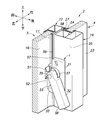
開放補助装置1は、支持部材としての、右窓4の召し合せ框19に取り付けられている。図2及び3に示すように、開放補助装置1は、召し合せ框19の左端面25に取り付けられるベース部材31と、ベース部材31に変位可能に支持された操作レバー32及び押圧部材33とを主として備える。ベース部材31は、ねじによって召し合せ框19に締結されている。
操作レバー32は、その一端に段付きの貫通孔35を備え、貫通孔35には一端に拡頭部を有するシャフト36が回転不能に結合されている。シャフト36の他端はベース部材31に回転可能に支持される。これにより、操作レバー32は、左右方向に延在するシャフト36の軸線Aを回転軸として、ベース部材31に回転可能に支持されている。操作レバー32の右側(ベース部材31側)には、半月状のクレセント37が取り付けられており、クレセント37は操作レバー32と一体に回動する。
操作レバー32の他端は、操作者に把持される把持部38となっている。図4に示すように、操作レバー32の長手方向における中間部であって、その下方への回動時に押圧部材33に対向する部分は角部を含んで斜めに切り欠かれており、押圧部材33と係合可能なカム面39を形成している。
押圧部材33は、コ字状のハウジング41に支持されたシャフト42に枢支されている。ベース部材31には、その左側部から前側部にかけて連続して開口するハウジング受容部43が形成されており、ハウジング41はハウジング受容部43に嵌め込まれ、固定される。ハウジング41がベース部材31に結合された状態で、シャフト42は上下方向に延在する。以上の構成により、押圧部材33は、シャフト42及びハウジング41を介して、上下方向に延びるシャフト42の軸線Bを回転軸としてベース部材31に回動可能に支持されている。
図2及び7に示すように、押圧部材33は、シャフト42に枢支された部分からシャフト42の径方向に延在する基部44を有している。基部44の先端には、シャフト42を中心とした接線方向の一方に突出する押圧端部45と、接線方向の他方に突出する被押圧端部46とが設けられている。すなわち、押圧部材33は、略T字状を呈している。押圧端部45の基部44の先端からの突出長さは、被押圧端部46の基部44の先端からの突出長さよりも長く、本実施形態では約5倍に設定されている。図2に示すように、被押圧端部46の先端部の上部は、滑らかな曲面47に形成されている。曲面47は、球面を含んでもよい。
ハウジング41と押圧部材33の基部44との間には、捻りコイルばね48が介装されている。捻りコイルばね48は、被押圧端部46の突出方向を向く回転方向(図7に示すように、下方から見て時計回りの方向)に押圧部材33を付勢している。図7に示すように、捻りコイルばね48に付勢された基部44は、一部がハウジング41に当接することによって回動が所定の位置で規制されている。このときの押圧部材33の位置を初期位置とする。押圧部材33が初期位置にあるときには、基部44は概ね左方へと延在し、押圧端部45の先端が右窓4の召し合せ框19よりも前方に突出しないように配置されている。また、被押圧端部46の先端部は、ベース部材31より左方に突出すると共に、押圧部材33の回転軸であるシャフト42よりも後方に配置されている。
図5に示すように、左窓3の召し合せ框12には、ストライカ51が組み合わされた受け部材52が取り付けられている。受け部材52は、上下方向に延在する扁平直方体状の部材であり、前後方向における厚みが左右方向の厚みに対して薄く形成されている。受け部材52の上部には、左端部53から右端部へと貫通する支持孔54が形成されている。ストライカ51は、一端部にクレセント37に係合可能な係合部を有し、他端側から支持孔54に挿入され、係合部が受け部材52に対して左方に突出した形態となっている。受け部材52の右端部には、上下方向に延在する切り欠き55が形成されている。切り欠き55が召し合せ框12の左側壁57及び後側壁58の境界に形成される角部59に係合した状態で、受け部材52及びストライカ51は一体に召し合せ框12に結合されている。受け部材52と召し合せ框12との結合は、ねじ締結や接着等の公知の結合方法を適用してよい。以上の構成により、受け部材52の左端部53は、召し合せ框12の左側壁57よりも左方に延出した状態となる。なお、受け部材52及びストライカ51は、前後方向において薄いため、左窓3及び右窓4が相対移動する際に、右窓4の召し合せ框19や戸先框18、板ガラス23に接触することはない。また、受け部材52は、初期位置にある押圧部材33の押圧端部45に接触することもない。
図1及び図2に示すように、クレセント37とストライカ51との係合および解除は、操作レバー32の回動によって選択的に切り替えられる。図2に示すように、操作レバー32の把持部38が操作レバー32の回転軸に対して下方に位置する状態では、クレセント37はストライカ51から離間し、係合は解除されている。この状態を解錠状態という。解錠状態から、図1に示すように、把持部38が操作レバー32の回転軸に対して上方に配置されるように、操作レバー32を回動させると、クレセント37がストライカ51の係合部に進入し、クレセント37とストライカ51とが係合した状態となる。この状態を施錠状態という。施錠状態では、左窓3及び右窓4の相対移動は規制され、サッシ窓2の開放が禁止される。
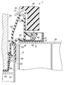
次に、図6~8を参照して、第1実施形態に係る開放補助装置1の動作について説明する。図6に示すように、クレセント37とストライカ51とが離間した解錠状態から、使用者が把持部38を掴み、操作レバー32を把持部38が操作レバー32の回転軸に対して下方に向かう方向(図6中において時計回りの方向、矢印70)に回動させると、図7に示すように操作レバー32のカム面39が押圧部材33の被押圧端部46の曲面47を前方へと押圧する。これにより、押圧部材33は、捻りコイルばね48の付勢力に抗して初期位置から押圧端部45が前方に突出する回転方向(図7中の反時計回り方向、矢印71)に回動する。カム面39は押圧部材33の曲面47上を摺動しながら、押圧部材33を前方へと回動させる。すなわち、操作レバー32は、押圧部材33を駆動する。
操作レバー32の回動(図6の矢印70の回転方向)が進むと、押圧部材33の押圧端部45が受け部材52の左端部53に左方から当接し、押圧端部45が受け部材52を右方へと押圧する。これにより、左窓3が右窓4に対して右方に相対移動する。
以上のように構成した開放補助装置1は、操作レバー32を回動操作することによって、押圧部材33を駆動し、押圧部材33によって左窓3の召し合せ框12を押圧し、左窓3を右窓4に対して右方に相対移動させることができる。このときの操作レバー32の回動操作は、クレセント37とストライカ51との係合を解除する操作と同じ方向の回動操作であるため、操作レバー32を回動する1つの操作で、サッシ窓2の解錠に引き続いてサッシ窓2の開放を行うことができる。
また、開放補助装置1では、押圧部材33が初期位置において右窓4の召し合せ框19から前方に突出しない(後方に引っ込んだ)構成となっているため、左窓3及び右窓4が相対移動する際に、押圧部材33が左窓3に接触することがなく、左窓3及び右窓4の相対移動に干渉しない。そのため、左窓3と右窓4とは、前後方向において互いに完全に重なる位置や、右窓4が左窓3よりも左方に変位した位置に移動することが可能になる。なお、本実施形態では押圧部材33が初期位置において召し合せ框19から前方に突出しない位置に配置したが、押圧部材33が召し合せ框19から前方に突出していたとしても、押圧部材33の前端部(押圧端部45)が、左窓3の召し合せ框12、受け部材52及び戸先框11よりも後方に配置され、これらとの間に隙間を形成していれば押圧部材33が左窓3の移動を阻害することはない。
(第2実施形態)
第2実施形態に係る開放補助装置100は、第1実施形態の開放補助装置1と比較して、ベース部材31、押圧部材33及び受け部材52の構成が異なる。開放補助装置100について、開放補助装置1と同様の構成については同一の符号を付し、説明を省略する。
第2実施形態に係る開放補助装置100は、第1実施形態の開放補助装置1と比較して、ベース部材31、押圧部材33及び受け部材52の構成が異なる。開放補助装置100について、開放補助装置1と同様の構成については同一の符号を付し、説明を省略する。
図9に示すように、開放補助装置100のベース部材101は、右側部において右窓4の召し合せ框19の左端面25に取り付けられ、左側部から前側部にかけて連続して開口する受容孔102が凹設されている。受容孔102の上縁部及び下縁部には、左方へと突出するガイドレール103が設けられている。各ガイドレール103には、左右方向に延在するガイドスロット104が形成されている。
押圧部材106は、左右方向に延在する筒状の基部107を備えている。基部107は、受容孔102に突入可能な大きさに形成されている。基部107の上部及び下部には、ガイド凸部108が突設されており、ガイド凸部108がガイドスロット104に係合することによって、基部107は受容孔102に対して左右方向に沿って所定の範囲で出没可能に支持される。押圧部材106が最も左方にあるときの位置(受容孔102から最も突出した位置)を初期位置、最も右方にあるときの位置(受容孔102に最も没入した位置)を駆動後位置とする。
基部107は、左端が閉塞されており、内部に圧縮コイルばね110の一端を受容している。圧縮コイルばね110の他端は、受容孔102の底部に当接している。これにより、押圧部材106は、圧縮コイルばね110によって初期位置へと付勢されている。
基部107の左端には、後方へと突出する被押圧端部109が形成されている。被押圧端部109の先端は、滑らかな曲面に形成されている。後述するが、被押圧端部109は、操作レバー32を回動させた際に、操作レバー32のカム面39に押圧される。
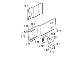
開放補助装置100では、開放補助装置1のストライカ51が組み合わされた受け部材52の代わりに、図10に示すように、ストライカ111と受け部材112とが互いに分離した状態で、左窓3の召し合せ框12に設けられている。ストライカ111は、ストライカ51と同様の係合部を有し、係合部が召し合せ框12より左方に突出するように、召し合せ框12にボルト締結されている。
受け部材112は、ホルダ113を介して召し合せ框12に支持されている。ホルダ113は、左右方向に延在した板状に形成され、右端部が召し合せ框12にボルト締結され、左端部が召し合せ框12よりも左方に延出している。ホルダ113の左端部の上部及び下部には後方へと突出する一対の互いに対向した支持片114が形成されている。両支持片114には、上下方向に貫通する支持孔115が形成されている。また、両支持片114には、支持孔115の左方に上下方向に貫通する係止孔116が形成されている。
受け部材112は、板状部材であって、上端面及び下端面の一側(基端側)にそれぞれ突設された軸117を有している。各軸117がホルダ113の支持孔115に回転可能に受容されることによって、受け部材112はホルダ113に回動可能に支持されている。受け部材112は、先端部(遊端部)が左方を向く第1位置と、先端部が後方を向く第2位置との間で回動可能になっている。すなわち、受け部材112は、略90°の回動範囲を有している。第1位置においては、受け部材112の主面がホルダ113に当接することによって回動範囲が規制され、第2位置においては、受け部材112の主面に突設された規制壁118がホルダ113に当接することによって回動範囲が規制されている。
受け部材112とホルダ113との間には捻りコイルばね119が介装されており、受け部材112は、捻りコイルばね119によって第1位置から第2位置へ向う回転方向に付勢されている。また、受け部材112の上端面及び下端面には、第1位置においてホルダ113の係止孔116に係止される係止突起120が突設されている。係止突起120が係止孔116に係止されることによって、受け部材112は捻りコイルばね118の付勢力に抗して第1位置に保持される。
受け部材112の先端部には、基端側へと延びる切り欠き121が形成されている。この切り欠き121によって、受け部材112の先端部は二股に分岐している。
図11及び12に示すように、受け部材112は、第2位置において先端部が右窓4の召し合せ框19の前側面よりも後方に突出している。各窓3、4の召し合せ框12、19が互いに対向したサッシ窓2の閉状態では、受け部材112は左右方向において押圧部材106の基部107とベース部材101との間に配置されている。また、受け部材112の切り欠き121内に圧縮コイルばね110が配置されている。
ベース部材101には、前方側へと突出する突片122が形成されている。突片122は、後述するが、受け部材112に当接して位置を変位させるために設けられている。
図12~14を参照して、開放補助装置100の動作を説明する。操作レバー32を回動することによって、クレセント37とストライカ111とが解錠状態と解錠状態との間で選択されるのは開放補助装置100と同様である。操作レバー32を把持部38が操作レバー32の回転軸に対して下方に向かう方向に回動させると、図12に示すように操作レバー32のカム面39が押圧部材106の被押圧端部109を右方へと押圧する。これにより、押圧部材106は、圧縮コイルばね110の付勢力に抗して初期位置から駆動後位置へと右方に変位する。カム面39は被押圧端部109上を摺動しながら、押圧部材106を右方へと変位させる。すなわち、操作レバー32は、押圧部材106を駆動する。
このとき、押圧部材106の基部107は、受け部材112を右方へと押圧する。受け部材112は、規制壁118によって回動が規制されているため、受け部材112は押圧部材106に押圧されてもホルダ113に対する姿勢を維持する。これにより、ホルダ113に結合されている左窓3が右窓4に対して右方に変位する。すなわち、左窓3が開放される。
図13に示すように、左窓3の右窓4に対する右方への変位が進むと、受け部材112はベース部材101の突片122に当接する。この状態から更に左窓3の右窓4に対する右方への変位が進むと、受け部材112は突片122に押圧され、捻りコイルばね119の付勢力に抗して、第2位置から第1位置へと回転する。これにより、図14に示すように、受け部材112は、突片122や召し合せ框19を避けることができ、左窓3の右窓4に対する右方への変位を阻害することがない。受け部材112が第1位置に到達すると、受け部材112の係止突起120がホルダ113の係止孔116に係止され、受け部材112は第1位置に保持される。
図14に示すような左窓3が右窓4に対して右方にある状態(開放状態)から、左窓3を右窓4に対して左方に変位させると、規制壁118が突片122に当接し、受け部材112に係止突起120が係止孔116から離脱するのに十分な荷重が加わる。これにより、係止突起120が係止孔116から離脱し、受け部材112は捻りコイルばね119の付勢力によって第2位置へと変位する。すなわち、図12の状態に戻り、受け部材112は押圧部材106によって押圧可能な位置に復帰する。
以上で具体的実施形態の説明を終えるが、本発明は上記実施形態に限定されることなく幅広く変形実施することができる。本実施形態では、受け部材52を召し合せ框12と別部材としたが、他の実施形態では受け部材52を召し合せ框12の一部として構成してもよい。
1,100…開放補助装置、3…左窓、4…右窓、12,19…召し合せ框、25…左端面、31、101…ベース部材、32…操作レバー、33、106…押圧部材、37…クレセント、44…基部、45…押圧端部、46…被押圧端部、51,111…ストライカ、52,112…受け部材、53…左端部、102…受容孔、104…ガイドスロット、109…被押圧端部、113…ホルダ、116…係止孔、118…規制壁、120…係止突起、122…突片
Claims (7)
- 引き戸を閉位置から開放する際の初期操作を補助する開放補助装置であって、
前記閉位置にある前記引き戸の戸尻部と対向するように設けられた支持部材と、
前記支持部材に変位可能に支持され、前記引き戸を開放する際に操作者が操作する操作部材と、
前記支持部材に変位可能に支持され、前記操作部材の変位に応じて駆動され、初期位置と駆動後位置との間で変位し、前記戸尻部を前記引き戸の開方向に押圧する押圧部材と
を有し、
前記押圧部材は、前記初期位置において、前記引き戸が開閉する際に前記引き戸と接触しないように、前記引き戸から離間して配置されていることを特徴とする開放補助装置。 - 前記戸尻部は、段部を形成するように前記支持部材側に突出した召し合せ框を備え、
前記押圧部材は、前記引き戸の開閉方向に沿った方向から前記召し合せ框を開方向に押圧することを特徴とする請求項1に記載の開放補助装置。 - 前記召し合せ框には、前記押圧部材によって押圧される被押圧部分が前記引き戸の面に沿って閉方向に突設されていることを特徴とする請求項2に記載の開放補助装置。
- 前記押圧部材は、前記初期位置と前記駆動後位置との間で回動可能に前記支持部材に支持されていることを特徴とする請求項2又は請求項3に記載の開放補助装置。
- 前記押圧部材は、回動軸の径方向に延在する基部と、前記基部の先端から前記回動軸を中心とした接線方向の一側に突出し、前記召し合せ框を押圧する押圧端部と、前記接線方向の他側に突出し、前記操作部材によって押圧される被押圧端部とを有し、前記被押圧端部の前記基部の先端からの突出長さは、前記押圧端部の前記基部の先端からの突出長さよりも長いことを特徴とする請求項4に記載の開放補助装置。
- 前記戸尻部は、前記引き戸の開閉方向に沿って延在する第1位置と前記引き戸の主面に対して起立した状態に延在する第2位置との間で回動可能に支持された被押圧部材と、前記被押圧部材を前記第2位置へと付勢する付勢部材とを有し、
前記被押圧部材は、前記第2位置に位置するときに、前記操作部材によって駆動された前記押圧部材に前記第1位置と相反する側へと押圧され、前記引き戸を開方向へと変位させる一方、前記引き戸が開方向に移動する際に前記支持部材に押圧されて前記第2位置から前記第1位置へと付勢部材の付勢力に抗して変位することを特徴とする請求項1に記載の開放補助装置。 - 前記戸尻部は、係止孔が形成されたホルダを有し、
前記支持部材は、前記戸尻部側に突出する突片を有し、
前記被押圧部材は、前記第1位置に位置するときに前記係止孔に係止される係止突起と、前記引き戸が開放された状態から前記閉位置へと変化する際に、前記突片に突き当たる係合凸部とを有し、前記係止突起が前記係止孔に係止されることによって前記付勢部材の付勢力に抗して前記第1位置に保持され、前記引き戸が開放された状態から前記閉位置へと変化する際に前記突片に前記係合凸部が押圧されることによって、前記係止突起と前記係止孔との係止構造を解除しつつ前記第2位置へと回転することを特徴とする請求項6に記載の開放補助装置。
Applications Claiming Priority (2)
| Application Number | Priority Date | Filing Date | Title |
|---|---|---|---|
| JP2011-133345 | 2011-06-15 | ||
| JP2011133345A JP2013002105A (ja) | 2011-06-15 | 2011-06-15 | 引き戸の開放補助装置 |
Publications (1)
| Publication Number | Publication Date |
|---|---|
| WO2012172734A1 true WO2012172734A1 (ja) | 2012-12-20 |
Family
ID=47356749
Family Applications (1)
| Application Number | Title | Priority Date | Filing Date |
|---|---|---|---|
| PCT/JP2012/003415 Ceased WO2012172734A1 (ja) | 2011-06-15 | 2012-05-25 | 引き戸の開放補助装置 |
Country Status (2)
| Country | Link |
|---|---|
| JP (1) | JP2013002105A (ja) |
| WO (1) | WO2012172734A1 (ja) |
Cited By (2)
| Publication number | Priority date | Publication date | Assignee | Title |
|---|---|---|---|---|
| US11008775B2 (en) * | 2015-12-03 | 2021-05-18 | Lawrence E Chaffin | Lift glide door lock assembly and lift glide window lock assembly and dual lift glide door lock assembly and dual lift glide window lock assembly |
| US20220112745A1 (en) * | 2020-10-14 | 2022-04-14 | Emtek Products, Inc. | Privacy Lock And Flush Pull With Integrated Strike Lockset |
Citations (3)
| Publication number | Priority date | Publication date | Assignee | Title |
|---|---|---|---|---|
| JPH08135302A (ja) * | 1994-11-14 | 1996-05-28 | Haseko Corp | サッシ |
| JP3927938B2 (ja) * | 2003-09-24 | 2007-06-13 | Ykk Ap株式会社 | 開放補助機構付き引手、およびサッシ窓 |
| JP2010196458A (ja) * | 2009-02-02 | 2010-09-09 | Nifco Inc | 開放補助機構付き引き手 |
-
2011
- 2011-06-15 JP JP2011133345A patent/JP2013002105A/ja active Pending
-
2012
- 2012-05-25 WO PCT/JP2012/003415 patent/WO2012172734A1/ja not_active Ceased
Patent Citations (3)
| Publication number | Priority date | Publication date | Assignee | Title |
|---|---|---|---|---|
| JPH08135302A (ja) * | 1994-11-14 | 1996-05-28 | Haseko Corp | サッシ |
| JP3927938B2 (ja) * | 2003-09-24 | 2007-06-13 | Ykk Ap株式会社 | 開放補助機構付き引手、およびサッシ窓 |
| JP2010196458A (ja) * | 2009-02-02 | 2010-09-09 | Nifco Inc | 開放補助機構付き引き手 |
Cited By (2)
| Publication number | Priority date | Publication date | Assignee | Title |
|---|---|---|---|---|
| US11008775B2 (en) * | 2015-12-03 | 2021-05-18 | Lawrence E Chaffin | Lift glide door lock assembly and lift glide window lock assembly and dual lift glide door lock assembly and dual lift glide window lock assembly |
| US20220112745A1 (en) * | 2020-10-14 | 2022-04-14 | Emtek Products, Inc. | Privacy Lock And Flush Pull With Integrated Strike Lockset |
Also Published As
| Publication number | Publication date |
|---|---|
| JP2013002105A (ja) | 2013-01-07 |
Similar Documents
| Publication | Publication Date | Title |
|---|---|---|
| TWI529290B (zh) | 多取用方式門鎖機構 | |
| JP6576628B2 (ja) | 車両用ドアのロック装置 | |
| TWI592560B (zh) | Lock device and sliding door with the lock device | |
| JP5358692B2 (ja) | 引き戸の開放補助装置 | |
| WO2012172734A1 (ja) | 引き戸の開放補助装置 | |
| JP5345503B2 (ja) | 開動助勢機構 | |
| KR100926467B1 (ko) | 전기정 스트라이커 | |
| JP2009189642A (ja) | 遊技機のヒンジ構造およびそのヒンジ構造を用いた遊技機 | |
| JP2011099219A5 (ja) | ||
| JP4368565B2 (ja) | 錠前の反転ラッチ用ストッパー機構 | |
| JP5007198B2 (ja) | 扉用錠装置 | |
| JP3386821B2 (ja) | 窓装置 | |
| KR101467284B1 (ko) | 래치볼트 고정레버의 작동장치 | |
| JP5727802B2 (ja) | ラッチ錠における内外気圧差解消装置 | |
| JP5942104B2 (ja) | 建具用ラッチ錠 | |
| JP5740166B2 (ja) | ラッチ錠における内外気圧差解消装置 | |
| JP5926016B2 (ja) | ラッチ錠における内外気圧差解消装置。 | |
| JP5330732B2 (ja) | プッシュプル電気錠 | |
| JP6384855B2 (ja) | 引き戸装置およびセーフティーストッパー | |
| JP2012097465A (ja) | 錠装置 | |
| JP5806888B2 (ja) | 開き戸用の内外気圧差解消装置 | |
| JP4514076B2 (ja) | 鎌錠 | |
| JP2014029096A (ja) | 引戸開放アシスト装置および引戸 | |
| JP4811368B2 (ja) | 引き戸の施開錠構造 | |
| JP4656435B2 (ja) | 建具 |
Legal Events
| Date | Code | Title | Description |
|---|---|---|---|
| 121 | Ep: the epo has been informed by wipo that ep was designated in this application |
Ref document number: 12800434 Country of ref document: EP Kind code of ref document: A1 |
|
| NENP | Non-entry into the national phase |
Ref country code: DE |
|
| 122 | Ep: pct application non-entry in european phase |
Ref document number: 12800434 Country of ref document: EP Kind code of ref document: A1 |