WO2012172693A1 - 磁性ファスナー - Google Patents
磁性ファスナー Download PDFInfo
- Publication number
- WO2012172693A1 WO2012172693A1 PCT/JP2011/063981 JP2011063981W WO2012172693A1 WO 2012172693 A1 WO2012172693 A1 WO 2012172693A1 JP 2011063981 W JP2011063981 W JP 2011063981W WO 2012172693 A1 WO2012172693 A1 WO 2012172693A1
- Authority
- WO
- WIPO (PCT)
- Prior art keywords
- magnetic
- main body
- tape
- fastener
- longitudinal direction
- Prior art date
- Legal status (The legal status is an assumption and is not a legal conclusion. Google has not performed a legal analysis and makes no representation as to the accuracy of the status listed.)
- Ceased
Links
Images







Classifications
-
- A—HUMAN NECESSITIES
- A44—HABERDASHERY; JEWELLERY
- A44B—BUTTONS, PINS, BUCKLES, SLIDE FASTENERS, OR THE LIKE
- A44B19/00—Slide fasteners
- A44B19/02—Slide fasteners with a series of separate interlocking members secured to each stringer tape
- A44B19/04—Stringers arranged edge-to-edge when fastened, e.g. abutting stringers
-
- A—HUMAN NECESSITIES
- A44—HABERDASHERY; JEWELLERY
- A44D—INDEXING SCHEME RELATING TO BUTTONS, PINS, BUCKLES OR SLIDE FASTENERS, AND TO JEWELLERY, BRACELETS OR OTHER PERSONAL ADORNMENTS
- A44D2203/00—Fastening by use of magnets
Definitions
- the present invention relates to a magnetic fastener. More specifically, the present invention relates to a fastener in which a plurality of magnetic elements are arranged along the tape longitudinal direction at opposing tape side edges of a pair of fastener tapes, and the magnetic elements can be connected using magnetic force.
- fasteners that can connect fastener elements by giving magnetism to the fastener elements have started to appear, and are expected to be used as new opening / closing tools for various articles.
- the magnetic fastener can open and close the opening of the article without using a slider, and since the fastener is connected by the attractive force of the magnet, a feeling of use different from that of the conventional slide fastener can be obtained.
- a method for imparting magnetism to a fastener element As a method for imparting magnetism to a fastener element, a method is known in which a magnet is embedded in a resin element member, or a mixture of a magnetic material and a synthetic resin material is injection molded and then magnetized to form an element. ing.
- a fastener element Magnetic member
- a fastener element is formed by embedding a magnet in a synthetic resin material of a thermoplastic resin or a thermosetting resin by insert molding.
- Patent Document 2 JP 2007-319253 A (Patent Document 2) describes that the head of each magnetic element is formed by embedding a magnet when injection molding a synthetic resin (paragraph of the document). 0015).
- the element head is provided with an engaging / disengaging convex part by projecting a part of the magnet in a columnar shape, while providing an engaging / disengaging concave part that can be fitted to the engaging / disengaging convex part.
- the head of each magnetic element may be formed by injection molding a synthetic resin containing a magnetic material and then magnetizing it.
- a recess may be provided in the center of the magnet in the longitudinal direction and embedded in the head of the magnetic element (paragraph 0071 of the document). ).
- Patent Document 3 a molding material in which a magnetic material containing iron oxide or neodymium and a synthetic resin such as nylon are mixed so as to straddle the front and back surfaces of the fastener tape.
- the magnetic element is formed into a predetermined shape by injection molding. Furthermore, it is described that the magnetic element formed into a predetermined shape is subjected to surface treatment such as aluminum vapor deposition, coating treatment, plating, etc., and then the magnetic element is magnetized in a strong magnetic field ( Paragraph 0070) of the document.
- Patent Document 1 JP-A-2006-149824
- Patent Document 2 JP-A-2007-319253
- Patent Document 3 instead of embedding a magnet in an element, a mixture of a magnetic material and a synthetic resin material is injection-molded and then magnetized to produce a magnetic element. A method has been proposed. However, in such a magnetic element, if the opening and closing of the fastener is repeated, the magnetic element is scraped by friction at the time of contact, so that there is a problem that it cannot withstand long-term use. Even if the periphery of the element is covered with metal plating or the like, it is difficult to completely solve the problem because the shape of the magnetic element is complicated.
- This invention is made
- a magnetic fastener in which a plurality of magnetic elements are arranged along the longitudinal direction of a tape at opposing tape side edges of a pair of fastener tapes, and the opposing magnetic elements are connected using magnetic force.
- Each of the magnetic elements includes a main body made of synthetic resin and a magnetic body embedded in the main body, and the two ends of the magnetic body in the longitudinal direction of the tape are exposed from the main body. Both exposed tips are magnetic fasteners in which the cross-sectional area perpendicular to the tape longitudinal direction gradually decreases with distance from the main body along the tape longitudinal direction.
- the magnetic body has a locking portion with the main body portion for preventing relative movement in the tape longitudinal direction with respect to the main body portion in the portion accommodated in the main body portion.
- the engaging portion has a cross section of the magnetic body orthogonal to the tape longitudinal direction, and the magnetic body is located within the main body portion more than the maximum cross sectional area at both exposed end portions. This is a shape in which the maximum cross-sectional area in the portion accommodated in the is larger.
- the exposed both ends are selected from a conical shape, a truncated cone shape, a truncated pyramid shape, a truncated pyramid shape, and a curved surface shape.
- both exposed end portions are spherical.
- the magnetic body is spherical.
- an engagement convex portion that enables engagement with a main body portion of a counterpart magnetic element coupled to the main body portion of the magnetic element, and the engagement convexity thereof.
- an engaging recess for receiving the portion is provided on the opposite side of the tape in the tape width direction of the magnetic body, and the engaging recess is on the magnetic body from the center of the magnetic body in the tape width direction. Is provided on the side of the fastener tape to which is fixed.
- the engaging projection protrudes in the tape longitudinal direction from the magnetic body.
- the present invention it is possible to provide a magnetic fastener that can withstand long-term use and is easy to manufacture. Further, in the main body portion of the magnetic element, there is an engagement convex portion that enables engagement with the main body portion of the mating magnetic element to be coupled and an engagement concave portion that receives the engagement convex portion. The resistance to the force in the direction of separating the magnetic fasteners in the connected state can be increased. Further, since the engaging convex portion protrudes in the tape longitudinal direction from the magnetic body, it is difficult to apply a force to the magnetic body against a force in a direction in which the magnetic fasteners in the connected state are separated.
- FIG. 4 is a sectional view taken along line B-B ′ in FIG. 3.
- FIG. 4 is a cross-sectional view taken along line B-B ′ when each magnetic element is separated in FIG. 3.
- FIG. 7 is a front view of FIG. 6.
- FIG. 2 is a perspective view of the magnetic fastener of the embodiment according to FIG. 1 when one of the magnetic elements attached to the fastener tape is viewed from the other surface side.
- FIG. 10 is a sectional view taken along line C-C ′ of FIG. 9.
- FIG. 3 is an excerpt of one of the magnetic elements extracted from FIG. 2.
- FIG. 11 is a cross section taken along line A-A ′ of FIG. 10. It is sectional drawing which shows typically the embedding state when the shape of a magnetic body is made into a column shape.
- each magnetic element includes a main body made of synthetic resin and a magnetic body embedded in the main body, and the two tips of the magnetic body in the longitudinal direction of the tape are both from the main body. Both of these exposed tip portions are gradually reduced in cross-sectional area perpendicular to the tape longitudinal direction as they are separated from the main body along the tape longitudinal direction.
- the magnetic body and the main body can be sandwiched from above and below when insert molding the magnetic body and the main body so positioning is easy and dimensional accuracy is improved. improves.
- the cross-sectional area perpendicular to the tape longitudinal direction of the exposed portion (tip portion) gradually decreases, the area where the magnetic bodies come into contact with each other when the magnetic elements are connected in the tape longitudinal direction is small.
- the risk of the magnetic body being scraped by friction during connection is reduced. As a result, it can withstand long-term use.
- the specific structure in which the cross-sectional area perpendicular to the longitudinal direction of the tape gradually decreases is not limited, but examples thereof include a conical shape, a truncated cone shape, a truncated pyramid shape, a truncated pyramid shape, and a curved surface shape. From the viewpoint of preventing scraping or chipping due to contact, it is preferable that the corners and ridges are chamfered. Further, it is preferable that the magnetic bodies are connected by point contact rather than surface contact because the contact area between the magnetic bodies becomes smaller. Examples of such a shape include a conical shape, a pyramid shape, and a curved surface shape. As a shape having a small contact area with little risk of scraping or chipping due to contact between magnetic bodies, a curved surface shape is mentioned, and a spherical shape is preferable.
- the portion accommodated in the main body is preferably 90% or less of the volume of the magnetic material.
- the magnetic body has a locking portion with the main body portion that prevents the movement of the main body portion in the tape longitudinal direction.
- a locking part By having such a locking part, it becomes possible to prevent the magnetic body from falling off the main body part.
- the maximum cross-sectional area in the portion where the magnetic body is accommodated in the main body is larger than the maximum cross-sectional area in both exposed tip portions. It can be made into such a shape.
- Such a shape is typically spherical, but is not limited thereto.
- the part accommodated in the main body part may be formed in a shape constricted in a direction orthogonal to the tape longitudinal direction, and one or a plurality of uneven portions may be formed in a direction orthogonal to the tape longitudinal direction.
- the N pole and the S pole are always arranged in the same direction in the tape longitudinal direction so that the magnetic elements can be connected in a straight line in the tape longitudinal direction.
- the magnetic element can be embedded in the fastener tape with the magnetic pole on the same side in the longitudinal direction of the magnetic body always set as the N pole (or S pole).
- a mark may be attached to the magnetic body.
- a mark for example, in addition to the marking method, there is a method of making the shape different on the N pole side and the S pole side.
- the main body can be asymmetrical in the tape longitudinal direction.
- the magnetic material is not limited.
- it can be a magnet, a ferrite, a rare earth magnet (neodymium, samarium cobalt), and neodymium is exemplified as one having a strong magnetic force.
- Ferrite can be inexpensive in terms of cost.
- neodymium magnets are preferred because of the strength of the magnetic force with respect to their size, and the use of neodymium magnets can reduce the size.
- magnets plastic magnets
- magnetized after injection molding a mixture of a magnetic material and a synthetic resin material into a predetermined shape may be used.
- the main body is formed of a material that is less likely to be scraped off due to wear during contact than the magnetic body.
- the main body of the magnetic element is made of synthetic resin, there is little risk of scraping or chipping due to friction during contact. For this reason, it is also possible to positively provide the main body portion with an uneven portion that enables engagement with the main body portion of the mating magnetic element to be connected.
- the synthetic resin used as the material for the main body is not particularly limited, and examples thereof include polyacetal and polybutylene terephthalate, and polyacetal is preferred for lubrication reasons.
- the material of the fastener tape is not particularly limited, but may be a soft fabric such as woven or knitted fabric, non-woven fabric, vinyl, or a hard fabric such as a plastic plate, a wooden plate, or a glass plate.
- the upper and lower stops may be attached to the magnetic fastener of the present invention.
- the magnetic fastener according to the present invention is not limited, but can be attached to, for example, an opening such as a clothes placket or a sleeve, an opening such as a bag or bag, or an opening of a structure such as a tent. .
- the longitudinal direction of the fastener tape is the vertical direction
- the upward direction on the paper surface is the upward direction
- the downward direction on the paper surface is the downward direction
- the width direction of the fastener tape is the left-right direction and the drawings are referred to
- the left direction on the paper surface is the left direction
- the right direction on the paper surface is the right direction
- the front and back direction of the tape is the front and back direction
- the front side of the paper is the front side
- the back side of the paper is the back side.
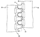
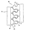
- FIG. 1 shows a state in which the magnetic elements 12 of the magnetic fastener 10 according to the present embodiment are separated
- FIG. 3 shows a state in which the magnetic elements 12 are connected.
- the magnetic fastener 10 according to the present embodiment includes a pair of left and right fastener tapes 11 and a plurality of magnetic tapes arranged at predetermined intervals along the tape longitudinal direction at opposing tape side edges of the pair of left and right fastener tapes 11. And an element 12.
- Each of the fastener tapes 11 has a core string 13 having an enormous cross-sectional view extending in the vertical direction at each side edge, and the magnetic element 12 is injection-molded (insert molding) so as to sandwich the core string 13 from the front and back.
- the magnetic elements 12 have the same shape, and the left magnetic element 12 row and the right magnetic element 12 row are front-back.
- the magnetic element 12 is fixed across the front and back surfaces of the fastener tape 11, and a spherical body made of neodymium magnet embedded in the main body 21 with the polyacetal main body 21, the upper end 14a and the lower end 14b exposed.
- the magnetic body 22 is provided.
- the upper end portion 14a is a portion exposed from the main body portion 21 on the upper side in the tape longitudinal direction of the main body portion 21, and the lower end portion 14b is a portion exposed from the main body portion 21 on the lower side in the tape longitudinal direction of the main body portion 21.
- the exposed upper and lower end portions 14a and 14b are also referred to as tip portions.
- the magnetic bodies 22 are arranged in a straight line in the vertical direction, and the left and right magnetic elements 12 are magnetized on the opposite side between one adjacent magnetic element 12. Element 12 enters and connects.
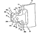
- FIGS. 6 and 7 show a state in which one of the magnetic elements 12 attached to the fastener tape 11 is viewed from the diagonally left front and from the front.
- FIGS. 8 and 9 show the magnetic element 12 as viewed from the diagonally rear left side and the true rear side, respectively.
- 10 is a cross-sectional view taken along the line CC ′ of FIG. 9
- FIG. 11 is an excerpt of one of the magnetic elements taken from FIG. 2
- FIG. 12 is a cross-sectional view taken along the line AA ′ of FIG. Are shown respectively.
- the configuration of the magnetic element 12 will be described in detail with reference to FIGS.
- the N pole and the S pole are always arranged in the same direction in the vertical direction so that the magnetic elements 12 can be connected side by side in the vertical direction.
- the magnetic body 22 has both the top and bottom ends 14a and 14b exposed from the main body 21, and the degree of exposure is about the same up and down. From FIG. 11 and FIG. 12, regarding the cross-sectional area of the magnetic body 22 in the cross section orthogonal to the tape longitudinal direction, the magnetic body 22 is located inside the main body portion 21 rather than the diameter X that gives the maximum cross-sectional area at both exposed end portions 14 a and 14 b. It can be understood that the diameter Y giving the maximum cross-sectional area in the portion accommodated in the container is larger, and it is difficult to drop off vertically.
- the main body portion 21 includes a leg portion 23 for fixing the magnetic element 12 to the fastener tape 11 by sandwiching the core string 13 at the tape side edge portion from the front and back, and a leg portion 23 toward the tape side edge portion facing the main portion 21. It has a head 24 that protrudes from the vicinity of the center in the vertical direction and has a cavity extending in the vertical direction for accommodating the magnetic body 22.
- the opposing magnetic elements 12 can be connected up and down along the vertical direction of the tape by the magnetic force of the magnetic body 22, but the main body 21 has engaging convex portions and engaging concave portions for reinforcing the connection at various places.
- the front and back surfaces of the main body 21 are located above the tip of the head 24.
- first members that receive the first engaging protrusions 25a.
- a third engagement member 26a receives the third engagement protrusion 25c at the lower end of the head 24.
- the second engagement recess 26b receives the second engagement protrusion 25b.
- a mating recess 26 c is present at the upper end of the head 24, and a fourth engagement recess 26 d that receives the fourth engagement projection 25 d is present above the base of the head 24.
- the magnetic fastener 10 in a connected state is pushed up to the front and back.
- the resistance force to the force in the direction can be increased (see FIGS. 4 and 5).
- the left and right magnetic elements 12 can be smoothly engaged and disengaged.
- the first engaging convex portion 25a has a mountain shape protruding upward, when engaged with the first engaging concave portion 26a having a corresponding valley shape, the magnetic fastener 10 in a connected state is formed.
- the 1st engagement convex part 25a becomes a taper shape which tapers upwards, engagement and disengagement of the left and right magnetic elements 12 can be performed smoothly. Further, in the present embodiment, the magnetic poles of the magnetic element 12 can be confirmed by using the first engaging convex portions 25a having a mountain shape protruding only upward.
- the engaging convex portions (25 a, 25 b, 25 c, 25 d) are moved to the engaging concave portions by bringing the magnetic elements in the left and right separated state closer to each other from the state separated from the front and back sides (26a, 26b, 26c, 26d) are received and connected. Since the upper and lower surfaces of the magnetic body are spherical, the connection from the front and back directions is performed smoothly, and bending in the front and back directions is easy. Further, when the magnetic elements are connected, there is a gap between the main body portions 21 adjacent to each other in the vertical direction because the magnetic body 22 is exposed from the main body portion 21 up and down. Easy to connect from the direction and easy to bend.
- the shape of the magnetic body 22 is spherical.
- a cylindrical shape as shown in FIG. 13 may be used, and the upper and lower bases of the cylindrical shape as shown in FIG. It is also possible to form a capsule.
- it is necessary to pay attention to the direction of the embedded portion and the range of the exposed portion so that the cross-sectional area perpendicular to the longitudinal direction of the tape gradually decreases at the exposed tip portion.
- the cross-sectional area of the magnetic body in a cross section orthogonal to the tape longitudinal direction the maximum cross-sectional area in the portion where the magnetic body is accommodated in the main body is larger than the maximum cross-sectional area in both exposed end portions.
- the magnetic body should be embedded in the direction in which the exposed portion of the magnetic body becomes the side surface of the cylinder, and the capsule-like magnetic body as shown in FIG.
- the main body portion accommodates part of the curved surfaces of the upper and lower bottoms so that the side surfaces of the magnetic body are not exposed.
- the columnar magnetic body shown in FIG. 13 is housed in the main body 21 with the center axis of the column parallel to the left-right direction.
- the dimension of the magnetic body in the left-right direction is constant, the cross section perpendicular to the left-right direction is circular, and the cross-sectional area at the cross section perpendicular to the tape longitudinal direction is represented by a rectangular area at the front end.
- the cross-sectional area of the portion accommodated in the main body 21 is larger than the cross-sectional area. If it is this shape, it will be easy to be smoothly connected with respect to one magnetic element, when the other magnetic element is connected by making it mutually approach from the state spaced apart from the front and back.
- the center axis of the columnar magnetic body shown in FIG. 13 may be directed in the front-back direction.
- the first engaging convex portion 25a protrudes in the tape longitudinal direction from the magnetic body 22, so that it is difficult for the force to be applied to the magnetic body with respect to the force in the separating direction at the time of connection. That is, the dimension from the base point to the tip of the first engaging convex portion 25a is formed larger than the dimension from the base point to the tip of the magnetic body 22 with the center in the tape longitudinal direction of the magnetic element 12 as the base point.
- the first engagement convex portion 25a is located on the opposite fastener tape side (the front end side of the main body portion) from the center in the tape width direction of the magnetic body, and the first engagement convex portion 25a of the magnetic element of the opposite fastener tape.
- the first engaging recess 26a that engages with the magnetic material is located closer to the fastener tape side to which the magnetic body 22 is fixed, that is, the base side (leg side) of the head 24 than the center of the magnetic body in the tape width direction.
- FIG. 15 Another shape of the magnetic body 22 is shown in FIG. 15, and here, the shape is different between the N pole side and the S pole side.
- the magnetic body 22 has a shape in which a part of the exposed lower end of the sphere is cut in a direction perpendicular to the vertical direction, the N pole side is a spherical surface, and the S pole side is a flat surface.
- the magnetic pole is not determined in advance, and even after magnetizing after injection molding with the magnetic body embedded in the main body, depending on the type of magnet, for example, neodymium is an anisotropic magnet, Since the direction of magnetization is determined, the direction can be matched to the mold also in that case. Note that the magnet is isotropic with respect to anisotropy, and if it is isotropic, it is not necessary to match the direction of magnetization. In general, anisotropic magnets have a stronger magnetic force than isotropic magnets.
- the main body 21 receives the first engagement convex portion 25 a that protrudes upward in the shape of a mountain at the tip of the head 24, and the first engagement convex portion 25 a below the base of the head 24.
- the trough-shaped first engaging recess 26a is provided, it is not necessary to have such a shape, and it is possible to finish the same shape as other engaging projections and engaging recesses.
- FIG. 16 is a front view showing an example of such a magnetic fastener, in which each magnetic element is separated.
- FIG. 17 shows a state where the magnetic elements of FIG. 16 are connected. Also in this modification, each magnetic element 12 has the same shape.
- the main body portion 21 is provided with only one engaging convex portion and one engaging concave portion.
- the front and back surfaces of the main body 21 approach the tip of the head 24.
- On the other side of the front and back surfaces in FIGS. 17 and 18, the front surface of the row of the left elements 12 and the back surface of the row of the right elements 12) are engaging concave portions 28 that receive the engaging convex portions 27. 24 below the root.
- the engagement convex portion 27 and the engagement concave portion 28 are engaged with each other on the front and back sides, so that the magnetic fastener 10 in a connected state is separated in the left and right directions in addition to the resistance force to pull the magnetic fastener 10 in the direction to separate the front and back surfaces.
- the resistance to the pulling force can also be increased.
- the left and right magnetic elements 12 can be smoothly engaged and disengaged. Since the engagement convex portion 27 has a tapered shape that tapers upward, the left and right magnetic elements 12 can be smoothly engaged and disengaged.
- the magnetic poles of the magnetic element 12 can be confirmed by using the engaging convex portions 27 having a mountain shape protruding only upward.
- FIG. 16 and 17 since the dimension in the tape longitudinal direction of the head 24 of the main body 21 is larger than the same dimension of the magnetic body 22, when viewed from the surface shown in FIG. The magnetic body 22 does not protrude from the main body portion 21 in the tape longitudinal direction.
- at the time of connection in addition to being connected close to each other from the front and back directions, they can be connected close to each other from the left and right directions.
- a magnetic body in which the central axis of the columnar magnetic body shown in FIG. 13 faces the front and back directions can also be used.
- the fastener tape is rotated with respect to the longitudinal direction of the tape, and one fastener tape is rotated with respect to the other fastener tape so that one fastener tape is orthogonal to the other fastener tape. You can also.
- FIG. 10 A further variation is shown in FIG.
- circular recesses are formed on the front and back surfaces of the head 24 with respect to the magnetic element 12 according to the present embodiment.
- the depression 29 is formed corresponding to the formation of a convex portion on the mold in order to further stabilize the position of the magnetic body by pressing in the front and back directions in the mold during the injection molding of the magnetic element 12. It is what is done.
Landscapes
- Slide Fasteners (AREA)
Abstract
長期間の使用に耐え、且つ、製造が容易な磁性ファスナーを提供する。一対のファスナーテープ11の対向し合うテープ側縁部にテープ長手方向に沿って複数の磁性エレメント12が列設され、対向するエレメント同士が磁力を利用して連結する磁性ファスナー10であって、各磁性エレメント12は合成樹脂製の本体部21と本体部21に埋設された磁性体22とを備え、磁性体22はテープ長手方向の二つの先端部14a、14bが共に本体部21から露出しており、これらの露出した先端部14は共にテープ長手方向に沿って本体部21から離れるに従いテープ長手方向に直交する断面積が漸次減少する磁性ファスナー。
Description
本発明は磁性ファスナーに関する。より詳細には、本発明は一対のファスナーテープの対向し合うテープ側縁部にテープ長手方向に沿って複数の磁性エレメントが列設され、磁力を利用して磁性エレメントを連結可能なファスナーに関する。
最近では、ファスナーエレメントに磁性を持たせることでファスナーエレメントを連結可能なファスナーが登場し始めており、各種物品の新たな開閉具として利用されることが期待されている。磁性ファスナーはスライダーを使用せずに物品の開口部の開閉を行うことができ、また、磁石の吸引力によりファスナーの連結が行われるため、従来のスライドファスナーとは異なる使用感が得られる。
ファスナーエレメントに磁性を付与する方法としては樹脂製のエレメント部材に磁石を埋設したり、磁性材料と合成樹脂材料を混合したものを射出成形した後、着磁してエレメントしたりする方法が知られている。
例えば、特開2006-149824号公報(特許文献1)では、ファスナーエレメント(磁性部材)を熱可塑性樹脂又は熱硬化性樹脂の合成樹脂材の中に磁石をインサート成形によって埋装することにより形成することが記載されている(当該文献の段落0024)。
例えば、特開2006-149824号公報(特許文献1)では、ファスナーエレメント(磁性部材)を熱可塑性樹脂又は熱硬化性樹脂の合成樹脂材の中に磁石をインサート成形によって埋装することにより形成することが記載されている(当該文献の段落0024)。
特開2007-319253号公報(特許文献2)では、各磁性エレメントの頭部が、合成樹脂を射出成形するときに磁石を埋設することにより形成されることが記載されている(当該文献の段落0015)。そして、エレメントの頭部には、磁石の一部を円柱状に突出させることにより係脱凸部を設ける一方で、当該係脱凸部に嵌着可能な係脱凹部を設けることが記載されている(特に当該文献の図12参照)。同段落には、各磁性エレメントの頭部は、磁性材料を含む合成樹脂を射出成形した後、着磁することにより形成してもよいことも開示されている。当該文献には更に、磁石が磁性エレメントから抜け落ちないようにするために、磁石の長手方向中央に凹みを設けて磁性エレメントの頭部に埋設すると良いことも記載されている(当該文献の段落0071)。
また、国際公開第2010/100744号(特許文献3)では、酸化鉄又はネオジウムを含む磁性材料と、ナイロン等の合成樹脂とが混合された成形材料を、ファスナーテープのテープ表裏面に跨るように射出成形することによって、磁性エレメントを所定の形状成形している。更に、所定の形状に成形された磁性エレメントには、アルミ蒸着等の表面処理や塗装処理、鍍金などを順次施し、その後、磁性エレメントを強い磁界の中で着磁することが記載されている(当該文献の段落0070)。
このように、磁性ファスナーは従来知られている。しかしながら、特開2006-149824号公報(特許文献1)や特開2007-319253号公報(特許文献2)に記載のような、熱可塑性樹脂又は熱硬化性樹脂の合成樹脂材の中に磁石をインサート成形によって埋装することにより、ファスナーエレメントを形成する方法では、金型内部に磁石を位置決めする必要があるが、精度良く金型に配置することは難しい。また、磁石が脱落する恐れがある。特開2007-319253号公報(特許文献2)では、脱落防止のために、磁石の長手方向中央に凹みを設けて磁性エレメントの頭部に埋設することが記載されているが、具体的形状は開示されていない。
国際公開第2010/100744号(特許文献3)では、エレメント内に磁石を埋設するのではなく、磁性材料と合成樹脂材料を混合したものを射出成形した後、着磁して磁性エレメントを製造する方法を提案しているが、このような磁性エレメントではファスナーの開閉を繰り返すと、接触時の摩擦によって磁性エレメントが削れてしまうので、長期間の使用に耐えられないという問題がある。金属めっきなどでエレメントの周囲を被覆したとしても、磁性エレメントの形状が複雑なため、完全に解決することは困難である。
本発明は上記事情に鑑みてなされたものであり、長期間の使用に耐え、且つ、製造が容易な磁性ファスナーを提供することを主たる課題とする。
本発明は一側面において、一対のファスナーテープの対向し合うテープ側縁部にテープ長手方向に沿って複数の磁性エレメントが列設され、対向する磁性エレメント同士が磁力を利用して連結する磁性ファスナーであって、各磁性エレメントは合成樹脂製の本体部と本体部に埋設された磁性体とを備え、磁性体はテープ長手方向の二つの先端部が共に本体部から露出しており、これらの露出した先端部は共にテープ長手方向に沿って本体部から離れるに従いテープ長手方向に直交する断面積が漸次減少する磁性ファスナーである。
本発明に係る磁性ファスナーは一実施形態において、磁性体は本体部に収容されている部分に、本体部に対するテープ長手方向への相対的な動きを妨げるための本体部との係止部を有する。
本発明に係る磁性ファスナーは別の一実施形態において、前記係止部は、テープ長手方向に直交する磁性体の断面積について、露出した両先端部における最大断面積よりも、磁性体が本体部内に収容されている部分における最大断面積の方が大きくなる形状である。
本発明に係る磁性ファスナーは更に別の一実施形態において、露出した両先端部は円錐状、円錐台状、角錐状、角錐台状及び曲面状から選択される。
本発明に係る磁性ファスナーは更に別の一実施形態において、露出した両先端部は球面状である。
本発明に係る磁性ファスナーは更に別の一実施形態において、磁性体は球状である。
本発明に係る磁性ファスナーは更に別の一実施形態において、磁性エレメントの本体部には連結される相手側の磁性エレメントの本体部との係合を可能とする係合凸部とその係合凸部を受容する係合凹部が存在し、係合凸部は磁性体のテープ幅方向中央よりも、対向するファスナーテープ側に備え、係合凹部は磁性体のテープ幅方向中央よりも当該磁性体が固定されているファスナーテープ側に備える。
本発明に係る磁性ファスナーは更に別の一実施形態において、前記係合凸部は、前記磁性体よりもテープ長手方向に突出する。
本発明によれば、長期間の使用に耐え、且つ、製造が容易な磁性ファスナーを提供することが可能となる。また、磁性エレメントの本体部に、連結される相手側の磁性エレメントの本体部との係合を可能とする係合凸部とその係合凸部を受容する係合凹部が存在することにより、連結した状態にある磁性ファスナーを引き離す方向への力に対する抵抗力を高めることができる。また、前記係合凸部が、前記磁性体よりもテープ長手方向に突出することにより、連結した状態にある磁性ファスナーを引き離す方向への力に対して、磁性体に力が加わりにくくできる。
本発明に係る磁性ファスナーにおいては、各磁性エレメントは合成樹脂製の本体部と本体部に埋設された磁性体とを備えており、磁性体はテープ長手方向の二つの先端部が共に本体部から露出しており、これらの露出した先端部は共にテープ長手方向に沿って本体部から離れるに従いテープ長手方向に直交する断面積が漸次減少する。
磁性体の本体部からの2箇所の露出部分を利用することで、磁性体と本体部をインサート成形するときに磁性体を上下から金型で挟むことができるので位置決めが容易となり、寸法精度が向上する。また、露出した部分(先端部)のテープ長手方向に直交する断面積が漸次減少する構成を採用したことで、磁性エレメントをテープ長手方向に連結させたときに磁性体同士が接触する面積が小さくなり、連結時の摩擦により磁性体が削れたりする危険性が軽減される。その結果、長期間の使用に耐えることができるようになる。テープ長手方向に直交する断面積が漸次減少する具体的な構造としては、限定的ではないが、例えば円錐状、円錐台状、角錐状、角錐台状及び曲面状が挙げられ、磁性体同士の接触により削れたり欠けたりするのを防止する観点からは角部や稜部が面取りされていることが好ましい。また、各磁性体は面接触よりも点接触で連結した方がお互いの接触面積の小さくなるので好ましい。そのような形状としては例えば円錐状、角錐状、又は曲面状が挙げられる。磁性体同士の接触による削れや欠けのおそれが少なく、接触面積も小さい形状としては曲面状が挙げられ、球面状とするのが好ましい。
磁性体の露出した先端部の大きさが過度に大きくなると連結時に磁性体同士が接触しやすくなり、また、本体部からの脱落もし易くなるので、磁性体の体積の50%以上が本体部に収容されていることが望ましい。ただし、磁性体の露出した部分の大きさが過度に小さくなるとインサート成形時の位置決め精度に影響を与えるので、本体部に収容される部分は磁性体の体積の90%以下とすることが好ましい。
本発明に係る磁性ファスナーの好ましい実施形態においては、磁性体は本体部に対するするテープ長手方向への動きを妨げる本体部との係止部を有する。このような係止部を有することで磁性体が本体部から脱落するのを防止できるようになる。例えば、テープ長手方向に直交する断面での磁性体の断面積について、露出した両先端部における最大断面積よりも、磁性体が本体部内に収容されている部分における最大断面積の方が大きくなるような形状とすることができる。そのような形状としては典型的には球状であるが、これに限定されるものではない。その他、本体部に収容された部分がテープ長手方向に直交する方向にくびれた形状とすることもでき、一又は複数の凹凸部をテープ長手方向に直交する方向に形成してもよい。
本発明に係る磁性ファスナーの好ましい実施形態においては、磁性体は、磁性エレメントがテープ長手方向に一直線上に連結可能になるように、テープ長手方向に常に同じ向きにN極とS極が配列されている。例えば、磁性体の長手方向の同一側の磁極を常にN極(又はS極)として磁性エレメントをファスナーテープに埋設することができる。この際、磁極の向きを間違えないようにするために、磁性体に目印を付けておいてもよい。目印としては、例えばマーキングする方法の他、N極側とS極側で異なる形状にするという方法もある。なお、磁性体を射出成形後に着磁する場合にはこのような目印は不要である。また、インサート成形後の磁性エレメントの磁極の向きをその形状のみで判断できるようにするため、テープ長手方向に本体部を非対称とすることもできる。
本発明に係る磁性ファスナーにおいては、磁性体としては、限定的ではないが、例えば、磁石、フェライト、希土類磁石(ネオジウム、サマリウムコバルト)とすることができ、磁力が強いものとしてネオジウムが挙げられる。フェライトはコスト面で安価とできる。磁石の中では、その大きさに対して磁力の強さが優位の理由によりネオジウム磁石が好ましく、ネオジウム磁石を使用すれば、小型化も可能である。また、磁石は、着磁したものの他に、磁性材料と合成樹脂材料を混合したものを所定形状に射出成形した後、着磁するもの(プラスチックマグネット)であってもよい。なお、本体部は磁性体よりも接触時の磨耗による削れが起こりにくい材料で形成される。また、磁性エレメントの本体部は合成樹脂製となっているので、接触時の摩擦によって削れたり欠けたりするおそれが少ない。このため、本体部には連結される相手側の磁性エレメントの本体部との係合を可能とする凹凸部を積極的に設けることも可能である。本体部の材料となる合成樹脂としては特に制限はないが、例えばポリアセタール、ポリブチレンテレフタレートなどが挙げられ、潤滑性の理由によりポリアセタールが好ましい。
ファスナーテープの材質は、特に制限されることはないが、織編布、不織布、ビニール、のような軟質生地のほか、プラスチック板、木板、ガラス板などの硬質生地であってもよい。
本発明の磁性ファスナーには上止めや下止めを取り付けてもよい。
本発明に係る磁性ファスナーは、限定的ではないが、例えば、衣服の前立てや袖部分などの開口部、バッグや袋物などの開口部、テントなどの構造物の開口部に取り付けることが可能である。
以下、本発明に係るファスナーの実施例について、図面を参照しながら詳細に説明する。
本実施例においては、ファスナーテープの長手方向を上下方向とし、図面を参照した場合、紙面上方向を上方向、紙面下方向を下方向とする。ファスナーテープの幅方向を左右方向とし、図面を参照した場合、紙面左方向を左方向、紙面右方向を右方向とする。また、テープの表裏方向を表裏方向とし、紙面手前側を表側、紙面奥側を裏側とする。
図1及び図3を参照すると、図1には本実施例に係る磁性ファスナー10の各磁性エレメント12が分離した状態が示されており、図3には各磁性エレメント12が連結した状態が示されている。本実施例に係る磁性ファスナー10は、左右一対のファスナーテープ11と、左右一対のファスナーテープ11の対向し合うテープ側縁部にテープ長手方向に沿って所定の間隔で列設された複数の磁性エレメント12とを備える。ファスナーテープ11はそれぞれ側縁部に上下方向に延びた断面視膨大状の芯紐13を有しており、磁性エレメント12は芯紐13を表裏から挟むように射出成形(インサート成形)される。
磁性エレメント12はそれぞれ同一形状であり、左側の磁性エレメント12の列と、右側の磁性エレメント12の列は表裏の関係にある。磁性エレメント12は、ファスナーテープ11の表裏面に跨って固着されており、ポリアセタール製の本体部21と上端部14a及び下端部14bが露出した状態で本体部21に埋設されたネオジウム磁石製の球状の磁性体22とを備える。上端部14aは本体部21のテープ長手方向上側において、本体部21から露出する部分であり、下端部14bは本体部21のテープ長手方向下側において、本体部21から露出する部分であり、この露出する上下端部14a,14bを先端部とも言う。左右の磁性エレメント12の列が完全に連結した状態にあるとき、磁性体22は上下方向に一直線状に並び、左右の磁性エレメント12は一方の隣り合う磁性エレメント12の間に対向する側の磁性エレメント12が入り込んで連結する。
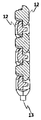
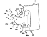
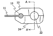
図6及び図7には、ファスナーテープ11に取着された磁性エレメント12の一つを左斜め正面及び真正面からみた様子がそれぞれ示されている。また、図8及び図9には、この磁性エレメント12を左斜め背面及び真背面からみた様子がそれぞれ示されている。更に、図10には図9のC-C’線断面図が、図11には図2から磁性エレメントの一つを取り出した抜粋図が、図12には図10のA-A’線断面がそれぞれ示されている。これら図6~図12を参照しながら磁性エレメント12の構成について詳述する。
磁性体22は、磁性エレメント12が上下方向に並んで連結可能にするため、上下方向に常に同じ向きにN極とS極が配列されている。また、磁性体22は上下方向の先端部14a、14bが共に本体部21から露出しており、露出の程度は上下同程度である。図11及び図12より、テープ長手方向に直交する断面における磁性体22の断面積について、露出した両先端部14a、14bにおける最大断面積を与える直径Xよりも、磁性体22が本体部21内に収容されている部分における最大断面積を与える直径Yの方が大きくなっており、上下に脱落しにくくなっていることが理解できる。
本体部21は、テープ側縁部の芯紐13を表裏から挟持することにより磁性エレメント12をファスナーテープ11に固着するための脚部23と、対向するテープ側縁部に向かって脚部23の上下方向中央付近から突設され、磁性体22を収容するための上下方向に延びた空洞を有する頭部24とを有する。
対向する磁性エレメント12同士は磁性体22がもつ磁力によってテープ上下方向に沿って上下に連結することができるが、本体部21は連結を補強するための係合凸部及び係合凹部を各所に有している。具体的には、本体部21の表裏一方の面(図1及び図3では、左側のエレメント12の列の表面及び右側のエレメント12の列の裏面)には、頭部24の先端に上方に張り出した第1係合凸部25a、頭部24の付け根上方に張り出した第2係合凸部25b、頭部24の付け根下方に張り出した第3係合凸部25c、及び頭部24の先端に下方に張り出した第4係合凸部25dが存在する。
本体部21の表裏他方の面(図1及び図3では、左側のエレメント12の列の裏面及び右側のエレメント12の列の表面)には、第1係合凸部25aを受容する第1係合凹部26aが頭部24の付け根下方に、第2係合凸部25bを受容する第2係合凹部26bが頭部24の先端下部に、第3係合凸部25cを受容する第3係合凹部26cが頭部24の先端上部に、そして第4係合凸部25dを受容する第4係合凹部26dが頭部24の付け根上方にそれぞれ存在する。
本体部21の表裏他方の面(図1及び図3では、左側のエレメント12の列の裏面及び右側のエレメント12の列の表面)には、第1係合凸部25aを受容する第1係合凹部26aが頭部24の付け根下方に、第2係合凸部25bを受容する第2係合凹部26bが頭部24の先端下部に、第3係合凸部25cを受容する第3係合凹部26cが頭部24の先端上部に、そして第4係合凸部25dを受容する第4係合凹部26dが頭部24の付け根上方にそれぞれ存在する。
これらの係合凸部(25a、25b、25c、25d)及び係合凹部(26a、26b、26c、26d)が表裏で係合することにより、連結した状態にある磁性ファスナー10を表裏への突き上げ方向への力に対する抵抗力を高めることができる(図4及び図5参照)。また、各係合凸部及び係合凹部の角を面取りすることで、左右の磁性エレメント12の係合及び脱係合をスムーズに行うことができるようにしている。
更に、第1係合凸部25aは上方に突出した山形状をしているので、これに対応する谷形状を有する第1係合凹部26aと係合したときには、連結した状態にある磁性ファスナー10を左右に分離する方向へ引っ張る力に対する抵抗力も高めることができる。また、第1係合凸部25aは上に向かって先細になるテーパー状となっているので、左右の磁性エレメント12の係合及び脱係合をスムーズに行うことができる。更に、本実施例では上方にのみ突出した山形状をしている第1係合凸部25aを目印にすることで磁性エレメント12の磁極を確認できる。
更に、第1係合凸部25aは上方に突出した山形状をしているので、これに対応する谷形状を有する第1係合凹部26aと係合したときには、連結した状態にある磁性ファスナー10を左右に分離する方向へ引っ張る力に対する抵抗力も高めることができる。また、第1係合凸部25aは上に向かって先細になるテーパー状となっているので、左右の磁性エレメント12の係合及び脱係合をスムーズに行うことができる。更に、本実施例では上方にのみ突出した山形状をしている第1係合凸部25aを目印にすることで磁性エレメント12の磁極を確認できる。
本実施例では、左右分離状態の磁性エレメントを、図5に示すように、表裏に離間した状態から互いに近づけることで、前記係合凸部(25a、25b、25c、25d)が前記係合凹部(26a、26b、26c、26d)に受容され、連結される。磁性体の上下面は球面状であるので、表裏方向からの連結が円滑に行われるとともに、表裏方向への曲げもしやすい。また、磁性エレメントが連結した状態のとき、上下に隣り合う本体部21同士の間には、磁性体22が本体部21から上下に露出した部分が存在することにより、隙間が存在するため、表裏方向からの連結が行いやすく、曲げも行いやすい。
本実施例では磁性体22の形状を球状としたが、例えば図13に示すような円柱状とすることも可能であり、図14に示すような円柱の上底及び下底を曲面状に盛り上がらせたカプセル状とすることも可能である。ただし、これらの形状の磁性体を使用するときは、露出した先端部において、テープ長手方向に直交する断面積が漸次減少するように埋設する向き及び露出部分の範囲に注意する必要がある。また、テープ長手方向に直交する断面での磁性体の断面積について、露出した両先端部における最大断面積よりも、磁性体が本体部内に収容されている部分における最大断面積の方が大きくなるような範囲で露出させることが脱落防止の観点から望ましい。すなわち、図13に示すような円柱状の磁性体を使用するときは、磁性体の露出部分が円柱の側面となる向きに磁性体を埋設すべきであり、図14に示すようなカプセル状の磁性体を上底及び下底の曲面を露出させるようにして使用するときは、磁性体の側面が露出しないように上底及び下底の曲面の一部を本体部が収容することが好ましい。
具体的には、図13に示す円柱状の磁性体は、円柱の中心軸が左右方向に平行となって本体部21に収容されている。そのため、磁性体の左右方向の寸法は一定で、左右方向に直交する断面が円形であり、先端部における、テープ長手方向に直交する断面での断面積は長方形の面積にて表され、先端部の断面積よりも、本体部21内に収容される部分の断面積が大きい。この形状であれば、一方の磁性エレメントに対し、他方の磁性エレメントが表裏に離間した状態から互いに近づけることで連結される際に、円滑に連結がされやすい。表裏方向に図14に示すカプセル状の磁性体は、上下方向の面を球面状とし、両球面の間が円柱状となって本体部21に収容されている。なお、図13に示す円柱状の磁性体の中心軸が表裏方向を向くようにすることもできる。
具体的には、図13に示す円柱状の磁性体は、円柱の中心軸が左右方向に平行となって本体部21に収容されている。そのため、磁性体の左右方向の寸法は一定で、左右方向に直交する断面が円形であり、先端部における、テープ長手方向に直交する断面での断面積は長方形の面積にて表され、先端部の断面積よりも、本体部21内に収容される部分の断面積が大きい。この形状であれば、一方の磁性エレメントに対し、他方の磁性エレメントが表裏に離間した状態から互いに近づけることで連結される際に、円滑に連結がされやすい。表裏方向に図14に示すカプセル状の磁性体は、上下方向の面を球面状とし、両球面の間が円柱状となって本体部21に収容されている。なお、図13に示す円柱状の磁性体の中心軸が表裏方向を向くようにすることもできる。
本実施例において、第1係合凸部25aは、磁性体22よりもテープ長手方向に突出していることで、連結時の引き離す方向への力に対して、磁性体に力が加わりにくくできる。つまり、磁性エレメント12のテープ長手方向の中心を基点として、その基点から磁性体22の先端までの寸法よりも、その基点から第1係合凸部25aの先端までの寸法が大きく形成される。
第1係合凸部25aは、磁性体のテープ幅方向中央よりも、対向するファスナーテープ側(本体部の先端側)に位置し、対向するファスナーテープの磁性エレメントの第1係合凸部25aと係合する第1係合凹部26aは、磁性体のテープ幅方向中央よりも、当該磁性体22が固定されているファスナーテープ側、すなわち頭部24の付け根側(脚部側)に位置する。
第1係合凸部25aは、磁性体のテープ幅方向中央よりも、対向するファスナーテープ側(本体部の先端側)に位置し、対向するファスナーテープの磁性エレメントの第1係合凸部25aと係合する第1係合凹部26aは、磁性体のテープ幅方向中央よりも、当該磁性体22が固定されているファスナーテープ側、すなわち頭部24の付け根側(脚部側)に位置する。
更なる磁性体22の別の形状が図15に示されており、ここではN極側とS極側で異なる形状となっている。具体的には磁性体22は、球の露出した下端部の一部を上下方向に対して直交する方向に切り取り、N極側を球面とし、S極側を平面とした形状となっている。これにより、磁極が既に決まっている磁性体を金型に向きを間違えて配置することを防止でき、生産効率が向上する。また、予め磁極が決まっておらず、本体部に磁性体を埋設した状態で射出成形した後に、着磁する場合であっても、磁石の種類によっては、例えばネオジウムは異方性磁石のため、着磁の際の方向が決まっているため、その場合にも、金型に向きを合わせることができる。なお、磁石は異方性に対して等方性があり、等方性はであれば、着磁の際の方向を合わせる必要はない。一般的に異方性の磁石は等方性の磁石よりも磁力が強い。
また、本実施例では本体部21は、頭部24の先端に上方に山形状に突出した第1係合凸部25a、及び頭部24の付け根下方に第1係合凸部25aを受容する谷形状の第1係合凹部26aを備えているが、このような形状にしなくてもよく、他の係合凸部及び係合凹部と同様の形状に仕上げることも可能である。そのような磁性ファスナーの一例について、各磁性エレメントが分離した状態を示す正面図を図16に示してある。図17には、図16の磁性エレメントが連結した状態を示す。この変形例でも各磁性エレメント12はそれぞれ同一形状である。
この変形例では本体部21に係合凸部と係合凹部が一箇所ずつのみ設けられている。具体的には、本体部21の表裏一方の面(図16及び図17では、右側のエレメント12の列の表面及び左側のエレメント12の列の裏面)には、頭部24の先端に向かうに従い上方に緩やかに傾斜し、頭部24の先端付近で下方に急傾斜する山形状の係合凸部27が存在する。また、表裏他方の面(図17及び図18では、左側のエレメント12の列の表面及び右側のエレメント12の列の裏面)には、係合凸部27を受容する係合凹部28が頭部24の付け根下方に存在する。
これらの係合凸部27及び係合凹部28が表裏で係合することにより、連結した状態にある磁性ファスナー10を表裏に分離する方向へ引っ張る力に対する抵抗力に加えて、左右に分離する方向へ引っ張る力に対する抵抗力も高めることができる。また、係合凸部及び係合凹部の角を面取りすることで、左右の磁性エレメント12の係合及び脱係合をスムーズに行うことができるようにしている。係合凸部27は上に向かって先細になるテーパー状となっているので、左右の磁性エレメント12の係合及び脱係合をスムーズに行うことができる。更に、本変形例では上方にのみ突出した山形状をしている係合凸部27を目印にすることで磁性エレメント12の磁極を確認できる。なお、本変形例(図16、17)では、本体部21の頭部24のテープ長手方向の寸法が磁性体22の同寸法よりも大きいことから、図16に示す表面から見たときに、磁性体22がテープ長手方向に本体部21から突出することがない。
なお、係合凸部を備えない本体部とし、連結時に表裏方向、左右方向の力に対して磁力のみで耐えるようにしてもよい。この場合には、連結時に、表裏方向から互いに近づけて連結する以外に、左右方向から互いに近づけて連結することもできる。この場合には、図13に示す円柱状の磁性体の中心軸が表裏方向を向くようにした磁性体を使用することもできる。一方の磁性エレメントに対し、他方の磁性エレメントが離間した状態から左右方向にて互いに近づけることで連結される際に、円滑に連結がされやすい。
さらに、連結した状態で、テープ長手方向を軸として、一方のファスナーテープを他方のファスナーテープに対して回動させ、一方のファスナーテープが他方のファスナーテープに対して直交するようにして使用することもできる。
さらに、連結した状態で、テープ長手方向を軸として、一方のファスナーテープを他方のファスナーテープに対して回動させ、一方のファスナーテープが他方のファスナーテープに対して直交するようにして使用することもできる。
更なる変形例が図18に示されている。この変形例では、本実施例に係る磁性エレメント12に対して、頭部24の表裏面に円形状の窪みが形成されている。当該窪み29は磁性エレメント12の射出成形時に金型内で表裏方向での押えを行うことにより、磁性体の位置を更に安定させるために、金型に凸部を形成したことに対応して形成されるものである。
以上、本発明の実施形態について図面を参照しながら説明してきたが、本発明はこれらの実施形態に限られるものではなく、種々のバリエーションが可能である。
10 磁性ファスナー
11 ファスナーテープ
12 磁性エレメント
13 芯紐
14a、14b 磁性体の露出した先端部
21 本体部
22 磁性体
23 脚部
24 頭部
25a~25d 係合凸部
26a~26d 係合凹部
27 係合凸部
28 係合凹部
29 窪み
11 ファスナーテープ
12 磁性エレメント
13 芯紐
14a、14b 磁性体の露出した先端部
21 本体部
22 磁性体
23 脚部
24 頭部
25a~25d 係合凸部
26a~26d 係合凹部
27 係合凸部
28 係合凹部
29 窪み
Claims (8)
- 一対のファスナーテープ11の対向し合うテープ側縁部にテープ長手方向に沿って複数の磁性エレメント12が列設され、対向するエレメント同士が磁力を利用して連結する磁性ファスナー10であって、各磁性エレメント12は合成樹脂製の本体部21と本体部21に埋設された磁性体22とを備え、磁性体22はテープ長手方向の二つの先端部14a、14bが共に本体部21から露出しており、これらの露出した先端部14は共にテープ長手方向に沿って本体部21から離れるに従いテープ長手方向に直交する断面積が漸次減少する磁性ファスナー。
- 磁性体22は、本体部に収容されている部分に、本体部に対するテープ長手方向への相対的な動きを妨げるための本体部との係止部を有する請求項1に記載の磁性ファスナー。
- テープ長手方向に直交する磁性体22の断面積について、露出した両先端部14a、14bにおける最大断面積よりも、磁性体22が本体部21内に収容されている部分における最大断面積の方が大きくなる形状の係止部を有する請求項2に記載の磁性ファスナー。
- 露出した両先端部14a、14bは円錐状、円錐台状、角錐状、角錐台状及び曲面状から選択される請求項1~3の何れか一項に記載の磁性ファスナー。
- 露出した両先端部14a、14bは球面状である請求項4に記載の磁性ファスナー。
- 磁性体22は球状である請求項5に記載の磁性ファスナー。
- 磁性エレメント12の本体部21には連結される相手側の磁性エレメント12の本体部21との係合を可能とする係合凸部とその係合凸部を受容する係合凹部が存在し、係合凸部は磁性体22のテープ幅方向中央よりも、対向するファスナーテープ側に備え、係合凹部は磁性体22のテープ幅方向中央よりも当該磁性体22が固定されているファスナーテープ側に備える請求項1~6の何れか一項に記載の磁性ファスナー。
- 前記係合凸部は、前記磁性体よりもテープ長手方向に突出してなる請求項7に記載の磁性ファスナー。
Priority Applications (3)
| Application Number | Priority Date | Filing Date | Title |
|---|---|---|---|
| JP2013520397A JP5599944B2 (ja) | 2011-06-17 | 2011-06-17 | 磁性ファスナー |
| CN201180070910.1A CN103619207B (zh) | 2011-06-17 | 2011-06-17 | 磁性拉链 |
| PCT/JP2011/063981 WO2012172693A1 (ja) | 2011-06-17 | 2011-06-17 | 磁性ファスナー |
Applications Claiming Priority (1)
| Application Number | Priority Date | Filing Date | Title |
|---|---|---|---|
| PCT/JP2011/063981 WO2012172693A1 (ja) | 2011-06-17 | 2011-06-17 | 磁性ファスナー |
Publications (1)
| Publication Number | Publication Date |
|---|---|
| WO2012172693A1 true WO2012172693A1 (ja) | 2012-12-20 |
Family
ID=47356719
Family Applications (1)
| Application Number | Title | Priority Date | Filing Date |
|---|---|---|---|
| PCT/JP2011/063981 Ceased WO2012172693A1 (ja) | 2011-06-17 | 2011-06-17 | 磁性ファスナー |
Country Status (3)
| Country | Link |
|---|---|
| JP (1) | JP5599944B2 (ja) |
| CN (1) | CN103619207B (ja) |
| WO (1) | WO2012172693A1 (ja) |
Cited By (4)
| Publication number | Priority date | Publication date | Assignee | Title |
|---|---|---|---|---|
| IT201600130023A1 (it) * | 2016-12-22 | 2018-06-22 | Aiani Jacopo | Cerniera lampo con chiusura a profili accoppiabili |
| JP2019502493A (ja) * | 2016-01-23 | 2019-01-31 | フィドロック・ゲーエムベーハーFidlock Gmbh | 2つの部品を着脱自在に連結するクロージャ装置 |
| WO2020144487A1 (en) * | 2019-01-10 | 2020-07-16 | Karoly Miklos Laszlo | Magnetic zipper structure, without slider |
| WO2024050609A1 (en) * | 2022-09-10 | 2024-03-14 | Perry John Underwood | A fastening system |
Families Citing this family (5)
| Publication number | Priority date | Publication date | Assignee | Title |
|---|---|---|---|---|
| CN109463850B (zh) * | 2018-10-17 | 2021-06-25 | 福建浔兴拉链科技股份有限公司 | 一种多面牙拉链 |
| CN109875145A (zh) * | 2019-03-30 | 2019-06-14 | 彭青珍 | 一种贴片式雨衣 |
| CN111869998A (zh) * | 2020-08-13 | 2020-11-03 | 安徽信息工程学院 | 一种防护性的拉链结构 |
| CN116471957B (zh) * | 2020-12-24 | 2025-10-28 | Ykk株式会社 | 拉链牙链带、拉链、及止码部件和拉链的制造方法 |
| CN117179426A (zh) * | 2023-10-11 | 2023-12-08 | 江苏盛业拉链科技有限公司 | 一种拉链牙及拉链结构 |
Citations (5)
| Publication number | Priority date | Publication date | Assignee | Title |
|---|---|---|---|---|
| JPS60261404A (ja) * | 1984-06-11 | 1985-12-24 | 中松 義郎 | マグネツトフアスナ |
| JPH0464209U (ja) * | 1990-10-17 | 1992-06-02 | ||
| JP2006149824A (ja) * | 2004-11-30 | 2006-06-15 | Ykk Corp | ファスナー |
| JP2007319253A (ja) * | 2006-05-30 | 2007-12-13 | Ykk Corp | ファスナー |
| WO2010100744A1 (ja) * | 2009-03-05 | 2010-09-10 | Ykk株式会社 | ファスナーチェーン及びファスナー |
-
2011
- 2011-06-17 CN CN201180070910.1A patent/CN103619207B/zh active Active
- 2011-06-17 JP JP2013520397A patent/JP5599944B2/ja active Active
- 2011-06-17 WO PCT/JP2011/063981 patent/WO2012172693A1/ja not_active Ceased
Patent Citations (5)
| Publication number | Priority date | Publication date | Assignee | Title |
|---|---|---|---|---|
| JPS60261404A (ja) * | 1984-06-11 | 1985-12-24 | 中松 義郎 | マグネツトフアスナ |
| JPH0464209U (ja) * | 1990-10-17 | 1992-06-02 | ||
| JP2006149824A (ja) * | 2004-11-30 | 2006-06-15 | Ykk Corp | ファスナー |
| JP2007319253A (ja) * | 2006-05-30 | 2007-12-13 | Ykk Corp | ファスナー |
| WO2010100744A1 (ja) * | 2009-03-05 | 2010-09-10 | Ykk株式会社 | ファスナーチェーン及びファスナー |
Cited By (6)
| Publication number | Priority date | Publication date | Assignee | Title |
|---|---|---|---|---|
| JP2019502493A (ja) * | 2016-01-23 | 2019-01-31 | フィドロック・ゲーエムベーハーFidlock Gmbh | 2つの部品を着脱自在に連結するクロージャ装置 |
| US11083251B2 (en) | 2016-01-23 | 2021-08-10 | Fidlock Gmbh | Closure device for detachably connecting two parts |
| IT201600130023A1 (it) * | 2016-12-22 | 2018-06-22 | Aiani Jacopo | Cerniera lampo con chiusura a profili accoppiabili |
| WO2018116033A1 (en) * | 2016-12-22 | 2018-06-28 | AIANI, Jacopo | Zip fastener with closure with couplable profiles |
| WO2020144487A1 (en) * | 2019-01-10 | 2020-07-16 | Karoly Miklos Laszlo | Magnetic zipper structure, without slider |
| WO2024050609A1 (en) * | 2022-09-10 | 2024-03-14 | Perry John Underwood | A fastening system |
Also Published As
| Publication number | Publication date |
|---|---|
| JP5599944B2 (ja) | 2014-10-01 |
| CN103619207A (zh) | 2014-03-05 |
| CN103619207B (zh) | 2015-11-25 |
| JPWO2012172693A1 (ja) | 2015-02-23 |
Similar Documents
| Publication | Publication Date | Title |
|---|---|---|
| JP5599944B2 (ja) | 磁性ファスナー | |
| US7320158B2 (en) | Fastener | |
| JP4610521B2 (ja) | ファスナー | |
| US9027210B2 (en) | Self-aligning zipper | |
| US20040244419A1 (en) | Connector for accessories | |
| JP4152216B2 (ja) | スライドファスナー用開離嵌挿具 | |
| JP6513675B2 (ja) | フックを有する保持デバイス、それを備える組立体、及び、前記保持デバイスを成形によって製作する方法 | |
| KR101703816B1 (ko) | 슬라이드 파스너 | |
| US5199138A (en) | Magnetic fastener | |
| EP0590206A1 (en) | Fastener | |
| US20130212841A1 (en) | Replacement zipper pull | |
| CN102726891A (zh) | 设有永磁体和机械锁定件的磁性紧固带扣 | |
| US20110167597A1 (en) | Multi-functional belt buckle | |
| TWI361052B (en) | Autolock slide for slide fastener | |
| WO2019186665A1 (ja) | バックル | |
| WO2012020499A1 (ja) | スライドファスナー | |
| US20100011544A1 (en) | Dual magnetic interlocking pin system | |
| CN103476465A (zh) | 高尔夫球杆头套 | |
| TWI555904B (zh) | A magnetic latch and a engaging device having the magnetic latch | |
| US20060084300A1 (en) | Magnetic construction kit adapted for use with construction blocks | |
| CN106880133B (zh) | 拉链用拉头 | |
| US20130344467A1 (en) | Systems and methods for providing couplable ornaments | |
| CN110580996B (zh) | 电磁线圈 | |
| EP2332154B1 (en) | Kit for quick attaching and disconnecting an item | |
| JP2014017394A (ja) | マグネットホルダおよびこれを用いた磁気保持装置、射出用金型 |
Legal Events
| Date | Code | Title | Description |
|---|---|---|---|
| 121 | Ep: the epo has been informed by wipo that ep was designated in this application |
Ref document number: 11867736 Country of ref document: EP Kind code of ref document: A1 |
|
| ENP | Entry into the national phase |
Ref document number: 2013520397 Country of ref document: JP Kind code of ref document: A |
|
| NENP | Non-entry into the national phase |
Ref country code: DE |
|
| 122 | Ep: pct application non-entry in european phase |
Ref document number: 11867736 Country of ref document: EP Kind code of ref document: A1 |