WO2012172618A1 - アレイマイクロホン装置および利得制御方法 - Google Patents
アレイマイクロホン装置および利得制御方法 Download PDFInfo
- Publication number
- WO2012172618A1 WO2012172618A1 PCT/JP2011/004746 JP2011004746W WO2012172618A1 WO 2012172618 A1 WO2012172618 A1 WO 2012172618A1 JP 2011004746 W JP2011004746 W JP 2011004746W WO 2012172618 A1 WO2012172618 A1 WO 2012172618A1
- Authority
- WO
- WIPO (PCT)
- Prior art keywords
- unit
- gain
- microphone
- signal
- microphone device
- Prior art date
Links
Images


Classifications
-
- H—ELECTRICITY
- H03—ELECTRONIC CIRCUITRY
- H03G—CONTROL OF AMPLIFICATION
- H03G3/00—Gain control in amplifiers or frequency changers without distortion of the input signal
- H03G3/20—Automatic control
-
- H—ELECTRICITY
- H04—ELECTRIC COMMUNICATION TECHNIQUE
- H04R—LOUDSPEAKERS, MICROPHONES, GRAMOPHONE PICK-UPS OR LIKE ACOUSTIC ELECTROMECHANICAL TRANSDUCERS; DEAF-AID SETS; PUBLIC ADDRESS SYSTEMS
- H04R29/00—Monitoring arrangements; Testing arrangements
- H04R29/004—Monitoring arrangements; Testing arrangements for microphones
- H04R29/005—Microphone arrays
- H04R29/006—Microphone matching
-
- H—ELECTRICITY
- H04—ELECTRIC COMMUNICATION TECHNIQUE
- H04R—LOUDSPEAKERS, MICROPHONES, GRAMOPHONE PICK-UPS OR LIKE ACOUSTIC ELECTROMECHANICAL TRANSDUCERS; DEAF-AID SETS; PUBLIC ADDRESS SYSTEMS
- H04R3/00—Circuits for transducers, loudspeakers or microphones
- H04R3/005—Circuits for transducers, loudspeakers or microphones for combining the signals of two or more microphones
-
- H—ELECTRICITY
- H04—ELECTRIC COMMUNICATION TECHNIQUE
- H04R—LOUDSPEAKERS, MICROPHONES, GRAMOPHONE PICK-UPS OR LIKE ACOUSTIC ELECTROMECHANICAL TRANSDUCERS; DEAF-AID SETS; PUBLIC ADDRESS SYSTEMS
- H04R1/00—Details of transducers, loudspeakers or microphones
- H04R1/20—Arrangements for obtaining desired frequency or directional characteristics
- H04R1/32—Arrangements for obtaining desired frequency or directional characteristics for obtaining desired directional characteristic only
- H04R1/40—Arrangements for obtaining desired frequency or directional characteristics for obtaining desired directional characteristic only by combining a number of identical transducers
- H04R1/406—Arrangements for obtaining desired frequency or directional characteristics for obtaining desired directional characteristic only by combining a number of identical transducers microphones
Definitions
- the present invention relates to an array microphone device, and more particularly to an array microphone device having a sensitivity correction function.
- an array microphone device is known as one of directional microphones.
- the array mylophone device has a plurality of microphones installed, and by processing the input sound, it can acquire spatial information of sound that cannot be obtained with a single microphone, and directivity control And the direction of sound arrival can be estimated.
- array microphone devices have come to be used for directivity control for sound collection at a high S / N ratio (Signal to Noise ratio) in remote sound collection and in-vehicle hands-free call system. .
- sensitivity correction function for automatically correcting the sensitivity of each microphone unit constituting the microphone array to the same characteristic.
- sensitivity correction means for performing sensitivity correction is provided before the directivity synthesis means for performing directivity synthesis. Even when the sensitivity of each microphone unit and the sensitivity of a circuit such as a microphone amplifier that accompanies each microphone unit (collectively referred to simply as the microphone unit sensitivity) are not the same due to changes over time or manufacturing reasons, the input signal The directivity synthesis means operates normally on the assumption that all levels are equal.
- the amount of gain update per time when the signal from each microphone unit is amplified or attenuated is large, the sound fluctuation or distortion rate may be deteriorated. .
- the sensitivity correction function always operates to cope with changes over time, the amount of gain update per time usually affects the sound quality and distortion rate of the sound collected by the array microphone device. It is necessary to make such a minute amount.
- the gain update amount is large, if the gain update amount per time is set to a minute amount, it takes a long time for the gain to converge.
- the present invention has been made in view of the above circumstances, and an object of the present invention is to provide an array microphone device and a gain control method that can maintain high-quality convergence in sensitivity correction while maintaining sound quality.
- the array microphone device of the present invention is an array microphone device having a microphone array composed of a plurality of microphone units, and the correction is performed by inputting a signal from a correction target microphone unit among the plurality of microphone units as a correction target signal.
- a gain control unit that controls a gain when amplifying or attenuating the correction target signal, and when the gain control unit is less than a predetermined time after the activation of the array microphone device, per unit time
- a first gain updater for changing the gain by a first change amount; and the elapsed time. If the it is more than a predetermined time, the second change amount per unit smaller time than the first change amount, and a second gain update unit for changing the gain.
- This configuration enables the sensitivity of the microphone unit to be corrected to be adjusted to the reference sensitivity at high speed during the startup operation of the array microphone device. Therefore, it is possible to reduce performance degradation due to directivity synthesis failure, shorten the inspection time in the inspection process at the time of manufacturing, and reduce the manufacturing cost.
- the sensitivity of the microphone unit to be corrected can be adjusted to the reference sensitivity at a low speed. Therefore, the sound quality such as the sound collected by the array microphone device is not affected by sound fluctuation and the distortion rate is not deteriorated.
- the gain control method of the present invention is a gain control method in an array microphone device having a microphone array composed of a plurality of microphone units, and a correction target signal input unit selects a correction target among the plurality of microphone units.
- a correction target signal input step for inputting a signal from the microphone unit as a correction target signal
- a reference signal input step for inputting a reference signal by a reference signal input unit, a level of the correction target signal, and a level of the reference signal
- a gain variable step for amplifying or attenuating the correction target signal so as to be substantially equal
- a gain control step for controlling a gain when the correction target signal is amplified or attenuated, the gain control step comprising: Elapsed time since activation of array microphone device is less than the specified time
- a first gain update step for changing the gain at a first change amount per unit time, and a unit time smaller than the first change amount when the elapsed time is equal to or longer than the predetermined time.
- This method makes it possible to quickly adjust the sensitivity of the microphone unit to be corrected to the reference sensitivity when the array microphone device is activated. Therefore, it is possible to reduce performance degradation due to directivity synthesis failure, shorten the inspection time in the inspection process at the time of manufacturing, and reduce the manufacturing cost.
- the sensitivity of the microphone unit to be corrected can be adjusted to the reference sensitivity at a low speed. Therefore, the sound quality such as the sound collected by the array microphone device is not affected by sound fluctuation and the distortion rate is not deteriorated.
- FIG. 1 is a block diagram showing a configuration example of an array microphone device according to a first embodiment of the present invention.
- the block diagram which shows the structural example of the sensitivity correction
- the flowchart which shows the operation example of the determination part in the 1st Embodiment of this invention, a high-speed gain update part, and a low-speed gain update part.
- the block diagram which shows the structural example of the sensitivity correction
- the flowchart which shows the operation example of the determination part in the 2nd Embodiment of this invention, a high-speed gain update part, and a low-speed gain update part.
- the microphone array 11 includes a first microphone unit 11a, a second microphone unit 11b, an (N-1) th microphone unit 11c, and an Nth microphone unit 11d.
- the microphone units 11a to 11d are arranged in a straight line.
- the number of microphone units is not limited to this.
- Each of the microphone units 11a to 11d usually has the same acoustic characteristics, but the level of the output signal may vary depending on the external environment, the period of use, and the like.
- the AD conversion unit 13 includes a first AD conversion unit 13a to which the first microphone unit 11a is connected, a second AD conversion unit 13b to which the second microphone unit 11b is connected, and an (N ⁇ 1) th microphone.
- the AD converter 13 (the AD converters 13a to 13d) converts the analog signal from the microphone array 11 into a digital signal.
- the sensitivity correction unit 15 includes a first sensitivity correction unit 15a corresponding to the first microphone unit 11a, a second sensitivity correction unit 15b corresponding to the second microphone unit 11b, and an (N-1) th microphone unit 11c. (N-1) th sensitivity correction unit 15c corresponding to the above. Details of the sensitivity correction unit 15 (the sensitivity correction units 15a to 15c) will be described later.
- the directivity synthesis unit 16 synthesizes the digital signals (output signals of the sensitivity correction units 15a to 15c) whose sensitivity has been corrected by the sensitivity correction unit 15 so as to direct the directivity in a specific direction.
- the directivity synthesis unit 16 includes an adaptive filter and an adder (not shown), and can determine the directivity by changing the calculation coefficient.
- Sound waves collected by the microphone array 11 are converted into digital signals via the microphone units 11a to 11d and the AD converters 13a to 13d.
- the converted digital signal is subjected to processing in the sensitivity correction units 15a to 15c and processing in the directivity synthesis unit 16 in the digital signal processing unit 14.
- the sampling frequency of the digital signal is 16 kHz, and the digital signal processing unit 14 also operates at this frequency.
- Each sensitivity correction unit 15a to each sensitivity correction unit 15c receives the output signal of the Nth microphone unit 13d as a reference signal, and the level of the output signal of each sensitivity correction unit 15a to 15c is from the Nth microphone unit 13d. Sensitivity correction is performed on each of the microphone units 11a to 11c so as to be substantially equal to the signal level. As a result, even when the sensitivity of the microphone units 11a to 11c varies, the level of the input signal to the directivity synthesis unit 16 becomes equal. Therefore, the directivity characteristic by the directivity synthesis unit 16 can be obtained correctly.
- FIG. 2 is a block diagram illustrating a configuration example of the sensitivity correction unit 15 (sensitivity correction units 15a to 15c).
- the sensitivity correction unit 15 includes a signal input unit 21, a reference signal input unit 22, a gain variable unit 23, a gain control unit 24, and a signal output unit 25.
- the signal input unit 21 inputs a digital signal from any of the AD conversion units 13a to 13c corresponding to any of the microphone units 11a to 11c to be corrected as a correction target signal.
- a digital signal from the AD conversion unit 13a corresponding to the microphone unit 11a to be corrected is input.
- the reference signal input unit 22 inputs a digital signal from the Nth AD conversion unit 13d corresponding to the Nth microphone unit 11d as a reference signal serving as a reference. That is, a signal from a microphone unit other than the microphone units 11a to 11c to be corrected is input as a reference signal among the plurality of microphone units. In addition, you may make it input a reference signal from the exterior of the array microphone apparatus 1 instead of the signal contained in a microphone unit.
- the gain variable unit 23 amplifies or attenuates the level of the signal from any of the AD conversion units 13a to 13c corresponding to any of the microphone units 11a to 11c to be corrected. At this time, the gain variable unit 23 amplifies or attenuates the correction target signal so that the level of the correction target signal and the level of the reference signal become substantially equal as a result of amplification or attenuation. For example, the correction target signal is amplified or attenuated so that the level of the correction target signal from the microphone unit 11a is substantially equal to the level of the reference signal from the microphone unit 11d.
- the gain control unit 24 controls an amplification amount or an attenuation amount (gain) when the gain variable unit 23 amplifies or attenuates the correction target signal. Details of the gain control unit 24 will be described later.
- the signal output unit 25 is an output terminal that outputs the signal amplified or attenuated by the gain variable unit 23, that is, the output signal of the gain variable unit 23, to the directivity synthesis unit 16.
- the band pass filter 26 includes a first band pass filter 26a that limits the pass band of the output signal of the gain variable unit 23, a second band pass filter 26b that limits the pass band of the reference signal from the reference signal input unit 22, Is provided. These pass bands are the same pass band.
- the absolute value calculator 27 calculates the absolute value of the signal from the first bandpass filter 26a, and the second absolute value calculator 27a calculates the absolute value of the signal from the second bandpass filter 26b.
- the absolute value calculation unit 27b calculates the absolute value of the signal from the first bandpass filter 26a.
- the subtraction unit 28 subtracts the calculation result by the second absolute value calculation unit 27b from the calculation result by the first absolute value calculation unit 27a.
- the determination unit 29 selects the high-speed gain update unit 210 or the low-speed gain update unit 211 in order to update the gain. For example, the determination unit 29 determines whether or not the elapsed time since the activation of the array microphone device 1 is less than a predetermined time (for example, 1 second), and selects the high-speed gain update unit 210 if it is less than the predetermined time. If it is longer than the predetermined time, the low-speed gain updating unit 211 is selected.
- a predetermined time for example, 1 second
- the high-speed gain update unit 210 updates the gain with a relatively large gain update amount (first change amount) per unit time.
- the low-speed gain update unit 211 updates the gain with a relatively small gain update amount (second change amount smaller than the first change amount) per unit time.
- a correction target signal from any of the microphone units 11a to 11c to be corrected input to the signal input unit 21 is received by the gain variable unit 23 by the gain control unit 24. Is amplified or attenuated according to the gain from the signal output from the signal output unit 25.
- the magnitude of the band-limited correction target signal is calculated as an absolute value by the first band pass filter 26a and the first absolute value calculation unit 27a.
- the magnitude of the reference signal band-limited by the second band pass filter 26b and the second absolute value operation unit 27b Is calculated as an absolute value.
- FIG. 3 is a flowchart illustrating an operation example of the determination unit 29, the high-speed gain update unit 210, and the low-speed gain update unit 211 of the present embodiment.
- the sensitivity difference (gain difference) between any one of the microphone units 11a to 11c to be corrected and the reference microphone unit 11d is ⁇ 4 dB at maximum, and the gain variable unit 23 needs to amplify the gain by ⁇ 4 dB.
- the gain is converged within 1 second after activation, and the sound quality is not affected by a small gain update amount after 1 second after activation.
- One second is an example.
- the high speed gain update unit 210 determines whether or not the subtraction result by the subtraction unit 28 is positive (step S103). When the result of subtraction by the subtracting unit 28 is positive, the level of the correction target signal from the gain variable unit 23 is higher than the level of the reference signal, so the high-speed gain updating unit 210 performs updating to reduce the gain ( Step S104). At this time, the high-speed gain update unit 210 sets the gain update amount per sampling period to, for example, ⁇ 0.00025 dB (corresponding to ⁇ 4 dB with 16000 samples as the number of samples per second).
- the high-speed gain updating unit 210 performs an update to increase the gain. (Step S105). At this time, the high-speed gain updating unit 210 sets the gain update amount per sampling period to, for example, +0.00025 dB (corresponding to +4 dB with 16000 samples as the number of samples per second).
- the high-speed gain update unit 210 updates the gain with the gain update amount, and sets the gain in the gain variable unit 23 (step S106).
- the high-speed gain update unit 210 corrects the sensitivity difference corresponding to the result subtracted by the subtracting unit 28 at a high speed within a predetermined time (for example, 1 second) after startup, thereby performing sensitivity correction (during gain update).
- a predetermined time for example, 1 second
- the directivity deterioration period can be shortened, and the waiting time in the inspection process can be shortened to the predetermined time (for example, 1 second).
- the determination unit 29 selects the low-speed gain update unit 211 (Yes in step S102).
- the high speed gain update unit 210 determines whether or not the subtraction result by the subtraction unit 28 is positive (step S107).
- the level of the correction target signal from the gain variable unit 23 is higher than the level of the reference signal, and thus the low-speed gain updating unit 211 performs updating to reduce the gain (step S108).
- the gain update amount per sampling period is set to, for example, -0.0000025 dB (corresponding to -0.04 dB with 16000 samples as the number of samples per second).
- the gain update amount per sampling period is set to, for example, +0.0000025 dB (corresponding to +0.04 dB for 16000 samples, which is the number of samples per second).
- the low-speed gain update unit 211 updates the gain with the gain update amount, and sets the gain in the gain variable unit 23 (step S106).
- the low-speed gain update unit 211 keeps the gain update amount at about ⁇ 0.04 dB per second, so that the sound quality is not deteriorated even if the gain is constantly updated, and the update operation is recognized by hearing. You can avoid it.
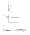
- FIG. 4 shows an example of gain update when the microphone units 11a to 11c to be corrected have a 4 dB sensitivity lower than that of the reference microphone unit 11d, that is, when the gain variable unit 23 needs to amplify 4 dB. Is.
- FIG. 4A is a diagram showing an example of gain update by the high-speed gain update unit 210.
- the gain update amount (first change amount) by the high-speed gain update unit 210 is, for example, the difference between the correction target signal and the reference signal and the high-speed gain update value update unit 210.
- the amount of change based on a period for performing gain update (for example, 1 second after activation), which is 1 dB or more per second.
- FIG. 4B is a diagram showing an example of gain update by the low-speed gain update unit 211.
- the gain of +4 dB is maintained after 1 second from the start-up, and the fluctuation of the gain is suppressed so as not to affect the sound quality. That is, the gain update amount (second change amount) by the low-speed gain update unit 211 is a change amount that is not perceived by hearing, and is, for example, less than 1 dB per second.
- FIG. 4C is a diagram showing a conventional gain update. Referring to FIG. 4C, if the gain update amount per sampling period that does not affect the sound quality is +0.0000025 dB, it will be understood that it takes 100 seconds to converge to a gain of +4 dB. it can.
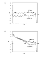
- FIG. 5 shows frequency characteristics of directivity of 0 degrees and 90 degrees when directivity synthesis is performed by the directivity synthesis unit 16 of the array microphone device 1 in two microphone units.
- FIG. 5A shows a case where 4 dB sensitivity correction is performed
- FIG. 5B shows a case where 4 dB sensitivity correction is not performed.
- a flat frequency characteristic is obtained as a directivity of 0 degree
- a frequency characteristic of a directivity of 0 degree is obtained as a flat frequency characteristic of 90 degrees.
- a flat frequency characteristic reduced by about 6 dB can be obtained. Therefore, it can be understood that directivity characteristics as designed can be obtained.
- the frequency characteristic of 0 degree directivity and the frequency characteristic of 90 degree directivity are not flat. Therefore, it can be understood that directivity characteristics as designed cannot be obtained.
- the level of each output signal (sensitivity-corrected correction target signal) of the sensitivity correction units 15a to 15c is a signal (reference signal) from the Nth microphone unit 11d.
- the gain of the gain variable section 23 is increased or decreased at high speed, and is increased or decreased at normal operation.
- FIG. 6 is a block diagram illustrating a configuration example of the sensitivity correction unit 15B (the sensitivity correction units 15a to 15c) according to the second embodiment of the present invention.
- the configuration of the sensitivity correction unit 15B shown in FIG. 6 of the present embodiment is basically the same as the sensitivity correction unit 15 shown in FIG. 2 of the first embodiment.
- the sensitivity correction unit 15B shown in FIG. 6 components having the same functions as those of the sensitivity correction unit 15 shown in FIG.
- the difference between FIG. 6 and FIG. 2 is that the output signal 31 a of the first absolute value calculator 27 a and the output signal 31 b of the second absolute value calculator 27 b are input to the determination unit 29.
- the output signal 31 a of the first absolute value calculator 27 a and the output signal 31 b of the second absolute value calculator 27 b are input to the determination unit 29.
- amendment part 15B in the array microphone apparatus 1 of this embodiment description is abbreviate
- FIG. 7 is a flowchart illustrating an operation example of the determination unit 29, the high-speed gain update unit 210, and the low-speed gain update unit 211 of the present embodiment.
- the determination unit 29 calculates the level sum of the level of the output signal 31a and the level of the output signal 31b (step S201). And it is determined whether this level sum is more than a threshold value (step S202).
- a threshold value for example, residual noise (eg, ⁇ 60 dBFS) of the microphone units 11a to 11c can be considered.
- the array microphone device 1 of the present embodiment has a high-speed gain update unit when the elapsed time after the sum of the level of the correction target signal and the level of the reference signal exceeds a predetermined value is less than the predetermined time.
- the gain is changed by 210 (an example of the first gain update unit), and when the elapsed time is equal to or longer than the predetermined time, the gain is changed by the low-speed gain update unit 211 (an example of the second gain update unit).
- the high-speed gain update unit 210 and the low-speed gain update unit 211 operate only when sufficient sound is collected by the microphone units 11a to 11c to be corrected and the microphone unit 11d that is the reference, and thus the inconvenience due to a minute level. Stable level judgment can be prevented.
- the sampling frequency, gain, operation time of the high-speed gain update unit 210, threshold value, and the like are not limited to those described above.
- the high-speed gain update unit 210 may determine the gain update amount from the gain and the allowable correction time.
- the low-speed gain update unit 211 may set the gain update amount to a level change amount that does not cause a sense of discomfort in the sense of hearing. In this case, for example, 0.1 dB or less per second is desirable.
- the present invention is useful for an array microphone device or the like that maintains sound quality and realizes high-speed convergence in sensitivity correction.
Abstract
音質を維持するとともに、感度補正における高速収束を実現するアレイマイクロホン装置等を提供する。 本アレイマイクロホン装置は、複数のマイクロホンユニット11a~11dにより構成されるマイクロホンアレイ11を有するアレイマイクロホン装置1であって、補正対象のマイクロホンユニット11a~11cからの信号を補正対象信号として入力する信号入力部21と、基準信号を入力する基準信号入力部22と、補正対象信号のレベルと基準信号のレベルとが略等しくなるよう、補正対象信号を増幅又は減衰させる利得可変部23と、補正対象信号を増幅又は減衰させるときの利得を制御する利得制御部24と、を備える。利得制御部24は、アレイマイクロホン装置1の起動からの経過時間が所定時間未満である場合、単位時間あたり第1の変化量で利得を変化させる高速利得更新部210と、経過時間が所定時間以上である場合、第1の変化量よりも小さい単位時間あたり第2の変化量で利得を変化させる低速利得更新部211と、を備える。
Description
本発明は、アレイマイクロホン装置に関し、特に、感度補正機能を有するアレイマイクロホン装置に関するものである。
従来、指向性マイクロホンの1つとして、アレイマイクロホン装置が知られている。アレイマイロホン装置は、複数のマイクロホンが設置されたものであり、入力された音声を信号処理することで、1つのマイクロホンでは得られないような音の空間的な情報が取得でき、指向性制御や音の到来方向の推定を行うことができる。近年においては、アレイマイクロホン装置は、遠隔収音や車室内ハンズフリー通話システムにおける高S/N比(Signal to Noise ratio)での収音のための指向性制御に用いられるようになってきている。
このようなアレイマイクロホン装置として、マイクロホンアレイを構成する各マイクロホンユニットの感度を自動的に同一特性に補正する機能(感度補正機能)を有するものが知られている(例えば、特許文献1参照)。このアレイマイクロホン装置では、指向性合成を行う指向性合成手段の前段に、感度補正を行う感度補正手段を設けられている。そして、各マイクロホンユニットの感度やそれに付随するマイクロホンアンプ等の回路の感度(これらをまとめて単にマイクロホンユニットの感度と呼ぶ)が、経時変化や製造上の理由等で同一でない場合でも、入力信号のレベルがすべて等しいという前提のもとに、指向性合成手段が正常に動作する。
しかしながら、従来のアレイマイクロホン装置では、各マイクロホンユニットからの信号を増幅又は減衰させるときの時間あたりの利得の更新量が大きい場合には、聴感上の音揺れや歪率の劣化を招くことがある。また、感度補正機能は経時変化にも対応するため常時動作しているので、通常、時間あたりの利得の更新量は、アレイマイクロホン装置で収音される音声などの音質や歪率に影響を与えないような微小量とする必要がある。さらに、利得の更新量が大きい場合に、時間あたりの利得の更新量を微小量とすると、利得の収束に長時間を要することになる。
これらの事情は、アレイマイクロホン装置の起動時における指向性合成不良による性能劣化や、アレイマイクロホン装置の製造時の検査工程における検査時間の増加による製造コストの増加をもたらす。
本発明は、上記事情に鑑みてなされたものであって、音質を維持するとともに、感度補正における高速収束を実現するアレイマイクロホン装置および利得制御方法を提供することを目的としたものである。
本発明のアレイマイクロホン装置は、複数のマイクロホンユニットにより構成されるマイクロホンアレイを有するアレイマイクロホン装置であって、前記複数のマイクロホンユニットのうち補正対象のマイクロホンユニットからの信号を補正対象信号として入力する補正対象信号入力部と、基準信号を入力する基準信号入力部と、前記補正対象信号のレベルと前記基準信号のレベルとが略等しくなるよう、前記補正対象信号を増幅又は減衰させる利得可変部と、前記補正対象信号を増幅又は減衰させるときの利得を制御する利得制御部と、を備え、前記利得制御部が、当該アレイマイクロホン装置の起動からの経過時間が所定時間未満である場合、単位時間あたり第1の変化量で、前記利得を変化させる第1の利得更新部と、前記経過時間が前記所定時間以上である場合、前記第1の変化量よりも小さい単位時間あたり第2の変化量で、前記利得を変化させる第2の利得更新部と、を備える。
この構成により、アレイマイクロホン装置の起動動作時には、補正対象のマイクロホンユニットの感度を基準となる感度に高速に合わせることができる。したがって、指向性合成不良による性能劣化を低減し、製造時の検査工程における検査時間を短縮し製造コストを削減することができる。
また、アレイマイクロホン装置の起動動作時移行の通常動作時には、補正対象のマイクロホンユニットの感度を基準となる感度に低速に合わせることができる。したがって、アレイマイクロホン装置で収音される音声などの音質に音揺れなどの影響を与えず、歪率も劣化しない。
つまり、音質の維持と感度補正の高速収束とを両立することができる。
また、本発明の利得制御方法は、複数のマイクロホンユニットにより構成されるマイクロホンアレイを有するアレイマイクロホン装置における利得制御方法であって、補正対象信号入力部により、前記複数のマイクロホンユニットのうち補正対象のマイクロホンユニットからの信号を補正対象信号として入力する補正対象信号入力ステップと、基準信号入力部により、基準信号を入力する基準信号入力ステップと、前記補正対象信号のレベルと前記基準信号のレベルとが略等しくなるよう、前記補正対象信号を増幅又は減衰させる利得可変ステップと、前記補正対象信号を増幅又は減衰させるときの利得を制御する利得制御ステップと、を有し、前記利得制御ステップが、前記アレイマイクロホン装置の起動からの経過時間が所定時間未満である場合、単位時間あたり第1の変化量で、前記利得を変化させる第1の利得更新ステップと、前記経過時間が前記所定時間以上である場合、前記第1の変化量よりも小さい単位時間あたり第2の変化量で、前記利得を変化させる第2の利得更新ステップと、を有する。
この方法により、アレイマイクロホン装置の起動動作時には、補正対象のマイクロホンユニットの感度を基準となる感度に高速に合わせることができる。したがって、指向性合成不良による性能劣化を低減し、製造時の検査工程における検査時間を短縮し製造コストを削減することができる。
また、アレイマイクロホン装置の起動動作時移行の通常動作時には、補正対象のマイクロホンユニットの感度を基準となる感度に低速に合わせることができる。したがって、アレイマイクロホン装置で収音される音声などの音質に音揺れなどの影響を与えず、歪率も劣化しない。
つまり、音質の維持と感度補正の高速収束とを両立することができる。
本発明によれば、音質を維持するとともに、感度補正における高速収束を実現することができる。
以下、本発明の実施形態について図面を参照して詳細に説明する。
(第1の実施形態)
図1は、本発明の第1の実施形態におけるアレイマイクロホン装置の構成例を示すブロック図である。図1に示すアレイマイクロホン装置1は、マイクロホンアレイ11、アナログデジタル変換部(以下、AD変換部という)13、デジタル信号処理部14、を有して構成される。
図1は、本発明の第1の実施形態におけるアレイマイクロホン装置の構成例を示すブロック図である。図1に示すアレイマイクロホン装置1は、マイクロホンアレイ11、アナログデジタル変換部(以下、AD変換部という)13、デジタル信号処理部14、を有して構成される。
マイクロホンアレイ11は、第1のマイクロホンユニット11a、第2のマイクロホンユニット11b、第(N-1)のマイクロホンユニット11c、第Nのマイクロホンユニット11d、を備える。各マイクロホンユニット11a~11dは、直線状に配列されている。また、マイクロホンユニットの数はこれに限られない。なお、各マイクロホンユニット11a~11dは、通常同様の音響特性を有しているが、外部環境、使用期間等により出力される信号のレベルが異なることがある。
AD変換部13は、第1のマイクロホンユニット11aが接続される第1のAD変換部13a、第2のマイクロホンユニット11bが接続される第2のAD変換部13b、第(N-1)のマイクロホンユニット11cが接続される第(N-1)のAD変換部13c、および、第Nのマイクロホンユニット11dが接続される第NのAD変換部13d、を備える。AD変換部13(各AD変換部13a~13d)は、マイクロホンアレイ11からのアナログ信号をデジタル信号に変換する。
デジタル信号処理部14は、各AD変換部13a~13dが接続され、各AD変換部13a~13dからのデジタル信号に対して各種のデジタル信号処理を行う。また、デジタル信号処理部14は、感度補正部15および指向性合成部16を備える。また、デジタル信号処理部14は、周知のCPU、ROM、RAM等を内蔵しており、内蔵するCPUがROMに格納されたプログラムを実行することにより、感度補正部15による感度補正機能や指向性合成部16による指向性合成機能を実現させる。
感度補正部15は、第1のマイクロホンユニット11aに対応する第1の感度補正部15a、第2のマイクロホンユニット11bに対応する第2の感度補正部15b、第(N-1)のマイクロホンユニット11cに対応する第(N-1)の感度補正部15c、を備える。感度補正部15(各感度補正部15a~15c)の詳細については後述する。
指向性合成部16は、特定の方向に指向性を向けるように、感度補正部15により感度補正された各デジタル信号(各感度補正部15a~15cの出力信号)を合成する。例えば、指向性合成部16は、図示しない適応フィルタや加算器により構成され、演算係数を変更することで、指向特性を定めることができる。
次に、アレイマイクロホン装置1の動作例について説明する。
マイクロホンアレイ11で収音された音波は、各マイクロホンユニット11a~11dと各AD変換部13a~13dとを介してデジタル信号に変換される。変換されたデジタル信号は、デジタル信号処理部14において、各感度補正部15a~15cの処理と、指向性合成部16の処理と、が施される。例えば、デジタル信号のサンプリング周波数は16kHzであり、本周波数でデジタル信号処理部14も動作する。
各感度補正部15a~各感度補正部15cは、第Nのマイクロホンユニット13dの出力信号を基準信号として入力し、各感度補正部15a~15cの出力信号のレベルが第Nのマイクロホンユニット13dからの信号のレベルと略等しくなるように、各マイクロホンユニット11a~11cの感度補正を行う。その結果、各マイクロホンユニット11a~11cの感度にばらつきがある場合であっても、指向性合成部16への入力信号のレベルは等しくなる。そのため、指向性合成部16による指向性特性が正しく得られる。
次に、感度補正部15の詳細について説明する。
図2は、感度補正部15(各感度補正部15a~15c)の構成例を示すブロック図である。図2に示すように、感度補正部15は、信号入力部21、基準信号入力部22、利得可変部23、利得制御部24、信号出力部25、を備える。
信号入力部21は、補正対象となる各マイクロホンユニット11a~11cのいずれかに対応する各AD変換部13a~13cのいずれかからのデジタル信号を補正対象信号として入力する。例えば、感度補正部15aの場合には、補正対象となるマイクロホンユニット11aに対応するAD変換部13aからのデジタル信号を入力する。
基準信号入力部22は、第Nのマイクロホンユニット11dに対応する第NのAD変換部13dからのデジタル信号を、基準となる基準信号として入力する。つまり、複数のマイクロホンユニットのうち、補正対象のマイクロホンユニット11a~11c以外のマイクロホンユニットからの信号を基準信号として入力している。なお、マイクロホンユニットに含まれる信号ではなく、アレイマイクロホン装置1の外部から基準信号を入力するようにしてもよい。
利得可変部23は、補正対象となる各マイクロホンユニット11a~11cのいずれかに対応する各AD変換部13a~13cのいずれかからの信号のレベルを増幅または減衰させる。このとき、利得可変部23は、増幅または減衰の結果、補正対象信号のレベルと基準信号のレベルとが略等しくなるように、補正対象信号を増幅または減衰させる。例えば、マイクロホンユニット11aからの補正対象信号のレベルとマイクロホンユニット11dからの基準信号のレベルとが略等しくなるように、補正対象信号を増幅または減衰させる。
利得制御部24は、利得可変部23により補正対象信号を増幅または減衰させるときの増幅量又は減衰量(利得)を制御する。利得制御部24の詳細については後述する。
信号出力部25は、利得可変部23により増幅または減衰された信号、つまり利得可変部23の出力信号を、指向性合成部16へ出力する出力端子などである。
次に、利得制御部24の詳細について説明する。
図2に示すように、利得制御部24は、帯域通過フィルタ26、絶対値演算部27、減算部28、判定部29、高速利得更新部210、および、低速利得更新部211、を備える。
帯域通過フィルタ26は、利得可変部23の出力信号の通過帯域を制限する第1の帯域通過フィルタ26a、基準信号入力部22からの基準信号の通過帯域を制限する第2の帯域通過フィルタ26b、を備える。これらの通過帯域は、同一の通過帯域である。
絶対値演算部27は、第1の帯域通過フィルタ26aからの信号の絶対値を算出する第1の絶対値演算部27a、第2の帯域通過フィルタ26bからの信号の絶対値を算出する第2の絶対値演算部27b、を備える。
減算部28は、第1の絶対値演算部27aによる演算結果から第2の絶対値演算部27bによる演算結果を減算する。
判定部29は、利得の更新を行うために、高速利得更新部210または低速利得更新部211を選択する。例えば、判定部29は、アレイマイクロホン装置1の起動からの経過時間が所定時間未満(例えば1秒間)であるか否かを判定し、所定時間未満である場合には高速利得更新部210を選択し、所定時間以上である場合には低速利得更新部211を選択する。
高速利得更新部210は、単位時間あたり比較的大きな利得更新量(第1の変化量)で、利得を更新する。
低速利得更新部211は、単位時間あたり比較的小さな利得更新量(第1の変化量よりも小さい第2の変化量)で、利得を更新する。
このように感度補正部15が構成されるので、信号入力部21へ入力された補正対象となるマイクロホンユニット11a~11cのいずれかからの補正対象信号は、利得可変部23により、利得制御部24からの利得に応じて増幅又は減衰され、信号出力部25より出力される。
また、利得可変部23の出力信号については、第1の帯域通過フィルタ26aと第1の絶対値演算部27aとによって、帯域制限された補正対象信号の大きさが絶対値として算出される。
一方、基準信号入力部22から入力されたマイクロホンユニット11dからの基準信号については、第2の帯域通過フィルタ26bと第2の絶対値演演算部27bとによって、帯域制限された基準信号の大きさが絶対値として算出される。
次に、高速利得更新部210および低速利得更新部211による利得更新例について説明する。
図3は、本実施形態の判定部29、高速利得更新部210、および低速利得更新部211の動作例を示すフローチャートである。
ここでは、補正対象となるマイクロホンユニット11a~11cのいずれかと基準となるマイクロホンユニット11dとの感度差(利得の差)が最大±4dBであり、利得可変部23によって±4dBの利得の増幅が必要であることを想定している。また、起動後1秒間で利得を収束させ、起動後1秒以降は微小な利得更新量で音質に影響を与えない仕様とする。なお、1秒間は一例である。
アレイマイクロホン装置1が電源投入によって起動すると、デジタル信号処理部14において、図示しない時間経過カウンターが、サンプリング周期毎に更新動作する。つまり計時を開始する(ステップS101)。続いて、判定部29は、時間経過カウンターが1秒未満であるか否かを判定する(ステップS102)。時間経過カウンターが1秒以上である場合には、判定部29が、高速利得更新部210を選択する(ステップS102のNo)。
続いて、高速利得更新部210は、減算部28による減算結果が正であるか否かを判定する(ステップS103)。減算部28による減算結果が正である場合には、基準信号のレベルよりも利得可変部23からの補正対象信号のレベルが大きいので、高速利得更新部210は、利得を小さくする更新を行う(ステップS104)。このとき、高速利得更新部210は、1サンプリング周期当たりの利得更新量を例えば-0.00025dB(1秒間におけるサンプル数である16000サンプルで-4dBに相当)に設定する。
また、減算部28による減算結果が負の場合には、基準信号のレベルよりも利得可変部23からの補正対象信号のレベルが小さいので、高速利得更新部210は、利得を大きくする更新を行う(ステップS105)。このとき、高速利得更新部210は、1サンプリング周期当たりの利得更新量を例えば+0.00025dB(1秒間におけるサンプル数である16000サンプルで+4dBに相当)に設定する。
そして、高速利得更新部210は、その利得更新量で利得を更新して、利得可変部23に利得を設定する(ステップS106)。
このように、高速利得更新部210によって、減算部28により減算された結果に対応する感度差を起動後所定時間(例えば1秒間)で高速に補正することで、感度補正中(利得更新中)の指向性劣化期間を短くし、検査工程における待ち時間も上記の所定時間(例えば1秒間)に短縮することができる。
一方、時間経過カウンターが1秒以上の場合には、判定部29が、低速利得更新部211を選択する(ステップS102のYes)。
続いて、高速利得更新部210は、減算部28による減算結果が正であるか否かを判定する(ステップS107)。減算部28による減算結果が正の場合には、基準信号のレベルより利得可変部23からの補正対象信号のレベルが大きいので、低速利得更新部211は、利得を小さくする更新を行う(ステップS108)。このとき、1サンプリング周期当たりの利得更新量を例えば-0.0000025dB(1秒間におけるサンプル数である16000サンプルで-0.04dBに相当)に設定する。
また、減算部28による減算結果が負の場合には、基準信号のレベルより利得可変部23からの補正対象信号のレベルが小さいので、低速利得更新部211は、利得を大きくする更新を行う(ステップS109)。このとき、1サンプリング周期当たりの利得更新量を例えば+0.0000025dB(1秒間におけるサンプル数である16000サンプルで+0.04dBに相当)に設定する。
そして、低速利得更新部211は、その利得更新量で利得を更新して、利得可変部23に利得を設定する(ステップS106)。
このように、低速利得更新部211によって、利得更新量を1秒間あたり±0.04dB程度に留めることで、利得の更新が常時実施されても、音質が劣化せず、更新動作を聴感上認識させないようにすることができる。
次に、高速利得更新部210または低速利得更新部211により更新される利得の更新例について説明する。
図4は、補正対象となるマイクロホンユニット11a~11cが、基準となるマイクロホンユニット11dより4dB感度が低い場合、つまり、利得可変部23によって4dBの増幅が必要である場合の利得の更新例を示すものである。
図4(a)は高速利得更新部210による利得の更新例を示す図である。図4(a)を参照すると、アレイマイクロホン装置1の起動1秒後には+4dBの利得に収束していることが理解できる。また、図4(a)に示すように、高速利得更新部210による利得更新量(第1の変化量)は、例えば、補正対象信号と基準信号との差および高速利得更値更新部210による利得更新を行う期間(例えば起動後1秒)に基づく変化量であり、1秒あたり1dB以上である。
図4(b)は低速利得更新部211による利得の更新例を示す図である。図4(b)を参照すると、起動1秒後以降は+4dBの利得を維持し、音質に影響を与えない程度の利得の揺れに抑えていることが理解できる。つまり、低速利得更新部211による利得更新量(第2の変化量)は、聴感上知覚されない変化量であり、例えば1秒あたり1dB未満である。
図4(c)は従来の利得更新を示す図である。図4(c)を参照すると、音質に影響を与えない程度の1サンプリング周期当たりの利得更新量を+0.0000025dBとすると、+4dBの利得に収束するには、100秒の時間を要することが理解できる。
次に、感度補正(利得更新)の有無による指向性の周波数特性について説明する。
図5は2つのマイクロホンユニットにおけるアレイマイクロホン装置1の指向性合成部16により指向性合成された場合の0度と90度の指向性の周波数特性を示すものである。また、図5(a)は4dBの感度補正が実施された場合を示しており、図5(b)は4dBの感度補正が実施されない場合を示している。
図5(a)を参照すると、本実施形態における感度補正が実施された場合、0度の指向性として平坦周波数特性が得られ、90度の平坦周波数特性として0度の指向性の周波数特性から約6dB低下した平坦周波数特性が得られる。したがって、設計通りの指向性特性が得られることが理解できる。一方、図5(b)を参照すると、本実施形態における感度補正が実施されない場合、0度の指向性の周波数特性および90度の指向性の周波数特性が平坦とならない。したがって、設計通りの指向性特性が得られないことが理解できる。
このような本実施形態のアレイマイクロホン装置1によれば、感度補正部15a~15cの各出力信号(感度補正された補正対象信号)のレベルが第Nのマイクロホンユニット11dからの信号(基準信号)のレベルと略等しくなるように、アレイマイクロホンアレイ装置1の起動時には、利得可変部23の利得を高速に増減させ、通常動作時は低速に増減させる。これにより、感度補正(利得更新)の高速収束と音質の維持とを両立して実現することができる。
(第2の実施形態)
図6は、本発明の第2の実施形態における感度補正部15B(各感度補正部15a~15c)の構成例を示すブロック図である。本実施形態の図6に示す感度補正部15Bの構成は、基本的には第1の実施形態の図2に示した感度補正部15と同様である。図6に示す感度補正部15Bにおいて、図2に示した感度補正部15と同一の機能を有するものには、同一の符号を付してその説明を省略する。図6と図2との差異は、第1の絶対値演算部27aの出力信号31aおよび第2の絶対値演算部27bの出力信号31bが、判定部29に入力されることである。なお、本実施形態のアレイマイクロホン装置1における感度補正部15B以外の構成については、第1の実施形態のアレイマイクロホン装置1と同様の構成であるので、説明を省略する。
図6は、本発明の第2の実施形態における感度補正部15B(各感度補正部15a~15c)の構成例を示すブロック図である。本実施形態の図6に示す感度補正部15Bの構成は、基本的には第1の実施形態の図2に示した感度補正部15と同様である。図6に示す感度補正部15Bにおいて、図2に示した感度補正部15と同一の機能を有するものには、同一の符号を付してその説明を省略する。図6と図2との差異は、第1の絶対値演算部27aの出力信号31aおよび第2の絶対値演算部27bの出力信号31bが、判定部29に入力されることである。なお、本実施形態のアレイマイクロホン装置1における感度補正部15B以外の構成については、第1の実施形態のアレイマイクロホン装置1と同様の構成であるので、説明を省略する。
図7は、本実施形態の判定部29、高速利得更新部210、および低速利得更新部211の動作例を示すフローチャートである。
本アレイマイクロホン装置1が電源投入によって起動すると、判定部29は、出力信号31aのレベルと出力信号31bのレベルとのレベル和を算出する(ステップS201)。そして、このレベル和が閾値以上であるか否かを判定する(ステップS202)。ここでの閾値とは、例えばマイクロホンユニット11a~11cの残留雑音(例えば-60dBFS)が考えられる。
レベル和が閾値以上であると判定された場合、デジタル信号処理部14において、時間経過カウンターが、更新動作する。つまり計時を開始する(ステップS203)。以降の動作は図3のステップS102~S109と同様である。一方、レベル和が閾値以下の場合は、利得制御部24は、利得可変部23の利得を更新しない(ステップS204)。
このように、本実施形態のアレイマイクロホン装置1は、補正対象信号のレベルと基準信号のレベルとの和が所定値以上となってからの経過時間が所定時間未満である場合、高速利得更新部210(第1の利得更新部の一例)により利得を変化させ、上記経過時間が所定時間以上である場合、低速利得更新部211(第2の利得更新部の一例)により利得を変化させる。
したがって、補正対象となるマイクロホンユニット11a~11cと基準となるマイクロホンユニット11dに十分音声が収音された場合のみ、高速利得更新部210および低速利得更新部211が動作することで、微小レベルによる不安定なレベル判定を防ぐことができる。
なお、サンプリング周波数、利得、高速利得更新部210の動作時間、閾値などは、上記説明したものに限定されるものではない。また、高速利得更新部210は、利得更新量を、利得と許容される補正時間から決定すればよい。また、低速利得更新部211は、利得更新量を、聴感上違和感のないレベル変化量とすればよい。この場合、例えば1秒間あたり0.1dB以下が望ましい。
本発明を詳細にまた特定の実施態様を参照して説明したが、本発明の精神と範囲を逸脱することなく様々な変更や修正を加えることができることは当業者にとって明らかである。
本出願は、2011年6月16日出願の日本特許出願No.2011-134562に基づくものであり、その内容はここに参照として取り込まれる。
本出願は、2011年6月16日出願の日本特許出願No.2011-134562に基づくものであり、その内容はここに参照として取り込まれる。
本発明は、音質を維持するとともに、感度補正における高速収束を実現するアレイマイクロホン装置等に有用である。
1 アレイマイクロホン装置
11 アレイマイクロホン
11a 第1のマイクロホンユニット
11b 第2のマイクロホンユニット
11c 第(N-1)のマイクロホンユニット
11d 第Nのマイクロホンユニット
13 アナログデジタル変換部(AD変換部)
13a 第1のアナログデジタル変換部
13b 第2のアナログデジタル変換部
13c 第(N-1)のアナログデジタル変換部
13d 第Nのアナログデジタル変換部
14 デジタル信号処理部
15、15B 感度補正部
15a 第1の感度補正部
15b 第2の感度補正部
15c 第(N-1)の感度補正部
16 指向性合成部
21 信号入力部
22 基準信号入力部
23 利得可変部
24 利得制御部
25 信号出力部
26 帯域通過フィルタ
26a 第1の帯域通過フィルタ
26b 第2の帯域通過フィルタ
27 絶対値演算部
27a 第1の絶対値演算部
27b 第2の絶対値演算部
28 減算部
29 判定部
210 高速利得更新部
211 低速利得更新部
31a 第1の絶対値演算部の出力信号
31b 第2の絶対値演算部の出力信号
Claims (7)
- 複数のマイクロホンユニットにより構成されるマイクロホンアレイを有するアレイマイクロホン装置であって、
前記複数のマイクロホンユニットのうち補正対象のマイクロホンユニットからの信号を補正対象信号として入力する補正対象信号入力部と、
基準信号を入力する基準信号入力部と、
前記補正対象信号のレベルと前記基準信号のレベルとが略等しくなるよう、前記補正対象信号を増幅又は減衰させる利得可変部と、
前記補正対象信号を増幅又は減衰させるときの利得を制御する利得制御部と、
を備え、
前記利得制御部は、
当該アレイマイクロホン装置の起動からの経過時間が所定時間未満である場合、単位時間あたり第1の変化量で、前記利得を変化させる第1の利得更新部と、
前記経過時間が前記所定時間以上である場合、前記第1の変化量よりも小さい単位時間あたり第2の変化量で、前記利得を変化させる第2の利得更新部と、
を備えるアレイマイクロホン装置。 - 請求項1に記載のアレイマイクロホン装置であって、
前記利得制御部は、前記補正対象信号のレベルと前記基準信号のレベルとの和が所定値以上となってからの経過時間が所定時間未満である場合、前記第1の利得更新部により利得を変化させ、前記経過時間が前記所定時間以上である場合、前記第2の利得更新部により利得を変化させるアレイマイクロホン装置。 - 請求項1または2に記載のアレイマイクロホン装置であって、
前記基準信号入力部は、前記基準信号として、前記複数のマイクロホンユニットのうち前記補正対象のマイクロホンユニット以外のマイクロホンユニットからの信号を入力するアレイマイクロホン装置。 - 請求項1ないし3のいずれか1項に記載のアレイマイクロホン装置であって、
前記第1の変化量は、前記補正対象信号のレベルと前記基準信号のレベルとの差、および、前記所定時間と、に基づく変化量であるアレイマイクロホン装置。 - 請求項1ないし3のいずれか1項に記載のアレイマイクロホン装置であって、
前記第2の変化量は、聴感上知覚されない変化量であるアレイマイクロホン装置。 - 請求項1ないし3のいずれか1項に記載のアレイマイクロホン装置であって、
前記第1の変化量は、1秒あたり1dB以上であり、
前記第2の変化量は、1秒あたり1dB未満であるアレイマイクロホン装置。 - 複数のマイクロホンユニットにより構成されるマイクロホンアレイを有するアレイマイクロホン装置における利得制御方法であって、
補正対象信号入力部により、前記複数のマイクロホンユニットのうち補正対象のマイクロホンユニットからの信号を補正対象信号として入力する補正対象信号入力ステップと、
基準信号入力部により、基準信号を入力する基準信号入力ステップと、
前記補正対象信号のレベルと前記基準信号のレベルとが略等しくなるよう、前記補正対象信号を増幅又は減衰させる利得可変ステップと、
前記補正対象信号を増幅又は減衰させるときの利得を制御する利得制御ステップと、
を有し、
前記利得制御ステップは、
前記アレイマイクロホン装置の起動からの経過時間が所定時間未満である場合、単位時間あたり第1の変化量で、前記利得を変化させる第1の利得更新ステップと、
前記経過時間が前記所定時間以上である場合、前記第1の変化量よりも小さい単位時間あたり第2の変化量で、前記利得を変化させる第2の利得更新ステップと、
を有する利得制御方法。
Priority Applications (4)
| Application Number | Priority Date | Filing Date | Title |
|---|---|---|---|
| JP2013520332A JP5895203B2 (ja) | 2011-06-16 | 2011-08-25 | アレイマイクロホン装置および利得制御方法 |
| EP11867814.3A EP2723103B1 (en) | 2011-06-16 | 2011-08-25 | Array microphone device and gain control method |
| CN201180071421.8A CN103597859B (zh) | 2011-06-16 | 2011-08-25 | 阵列话筒装置和增益控制方法 |
| US14/102,007 US9337794B2 (en) | 2011-06-16 | 2013-12-10 | Array microphone device and gain control method |
Applications Claiming Priority (2)
| Application Number | Priority Date | Filing Date | Title |
|---|---|---|---|
| JP2011134562 | 2011-06-16 | ||
| JP2011-134562 | 2011-06-16 |
Related Child Applications (1)
| Application Number | Title | Priority Date | Filing Date |
|---|---|---|---|
| US14/102,007 Continuation US9337794B2 (en) | 2011-06-16 | 2013-12-10 | Array microphone device and gain control method |
Publications (1)
| Publication Number | Publication Date |
|---|---|
| WO2012172618A1 true WO2012172618A1 (ja) | 2012-12-20 |
Family
ID=47356646
Family Applications (1)
| Application Number | Title | Priority Date | Filing Date |
|---|---|---|---|
| PCT/JP2011/004746 WO2012172618A1 (ja) | 2011-06-16 | 2011-08-25 | アレイマイクロホン装置および利得制御方法 |
Country Status (5)
| Country | Link |
|---|---|
| US (1) | US9337794B2 (ja) |
| EP (1) | EP2723103B1 (ja) |
| JP (1) | JP5895203B2 (ja) |
| CN (1) | CN103597859B (ja) |
| WO (1) | WO2012172618A1 (ja) |
Families Citing this family (8)
| Publication number | Priority date | Publication date | Assignee | Title |
|---|---|---|---|---|
| WO2017033260A1 (ja) * | 2015-08-24 | 2017-03-02 | ヤマハ株式会社 | 収音装置および収音方法 |
| KR102502601B1 (ko) * | 2015-11-27 | 2023-02-23 | 삼성전자주식회사 | 전자 장치 및 음성 신호 제어 방법 |
| CN107360528A (zh) * | 2017-06-07 | 2017-11-17 | 歌尔股份有限公司 | 一种基于麦克风阵列的校准方法及装置 |
| CN107249165A (zh) * | 2017-06-30 | 2017-10-13 | 歌尔股份有限公司 | 麦克风灵敏度调整系统及方法 |
| CN107509155B (zh) * | 2017-09-29 | 2020-07-24 | 广州视源电子科技股份有限公司 | 一种阵列麦克风的校正方法、装置、设备及存储介质 |
| US10405115B1 (en) * | 2018-03-29 | 2019-09-03 | Motorola Solutions, Inc. | Fault detection for microphone array |
| EP4147229A1 (en) | 2020-05-08 | 2023-03-15 | Nuance Communications, Inc. | System and method for data augmentation for multi-microphone signal processing |
| CN111510843B (zh) * | 2020-05-12 | 2021-11-23 | 无锡韦感半导体有限公司 | Mems麦克风的修调装置及其修调方法 |
Citations (5)
| Publication number | Priority date | Publication date | Assignee | Title |
|---|---|---|---|---|
| JPH07131886A (ja) | 1993-11-05 | 1995-05-19 | Matsushita Electric Ind Co Ltd | アレイマイクロホンおよびその感度補正装置 |
| JP2001177900A (ja) * | 1999-12-17 | 2001-06-29 | Sony Corp | 音声信号記録装置 |
| JP2002540696A (ja) * | 1999-03-19 | 2002-11-26 | シーメンス アクチエンゲゼルシヤフト | ノイズ音響に満ちた環境でのオーディオ信号の受信と処理のための方法 |
| JP2003259479A (ja) * | 2002-03-04 | 2003-09-12 | Matsushita Electric Ind Co Ltd | マイクロホン装置 |
| JP2011134562A (ja) | 2009-12-24 | 2011-07-07 | Teijin Ltd | 非水系二次電池用セパレータ及び非水系二次電池 |
Family Cites Families (9)
| Publication number | Priority date | Publication date | Assignee | Title |
|---|---|---|---|---|
| US6707912B2 (en) * | 1999-03-11 | 2004-03-16 | Motorola, Inc. | Method and apparatus for setting a step size for an adaptive filter coefficient of an echo canceller |
| US7333605B1 (en) * | 2002-04-27 | 2008-02-19 | Fortemedia, Inc. | Acoustic echo cancellation with adaptive step size and stability control |
| US8767972B2 (en) * | 2006-08-16 | 2014-07-01 | Apherma, Llc | Auto-fit hearing aid and fitting process therefor |
| US20080175407A1 (en) * | 2007-01-23 | 2008-07-24 | Fortemedia, Inc. | System and method for calibrating phase and gain mismatches of an array microphone |
| US8855330B2 (en) * | 2007-08-22 | 2014-10-07 | Dolby Laboratories Licensing Corporation | Automated sensor signal matching |
| US20090323980A1 (en) * | 2008-06-26 | 2009-12-31 | Fortemedia, Inc. | Array microphone system and a method thereof |
| CN101668243B (zh) * | 2008-09-01 | 2012-10-17 | 华为终端有限公司 | 一种麦克风阵列及麦克风阵列校准的方法和模块 |
| US8731210B2 (en) | 2009-09-21 | 2014-05-20 | Mediatek Inc. | Audio processing methods and apparatuses utilizing the same |
| KR101601197B1 (ko) * | 2009-09-28 | 2016-03-09 | 삼성전자주식회사 | 마이크로폰 어레이의 이득 조정 장치 및 방법 |
-
2011
- 2011-08-25 JP JP2013520332A patent/JP5895203B2/ja active Active
- 2011-08-25 EP EP11867814.3A patent/EP2723103B1/en active Active
- 2011-08-25 WO PCT/JP2011/004746 patent/WO2012172618A1/ja active Application Filing
- 2011-08-25 CN CN201180071421.8A patent/CN103597859B/zh active Active
-
2013
- 2013-12-10 US US14/102,007 patent/US9337794B2/en active Active
Patent Citations (5)
| Publication number | Priority date | Publication date | Assignee | Title |
|---|---|---|---|---|
| JPH07131886A (ja) | 1993-11-05 | 1995-05-19 | Matsushita Electric Ind Co Ltd | アレイマイクロホンおよびその感度補正装置 |
| JP2002540696A (ja) * | 1999-03-19 | 2002-11-26 | シーメンス アクチエンゲゼルシヤフト | ノイズ音響に満ちた環境でのオーディオ信号の受信と処理のための方法 |
| JP2001177900A (ja) * | 1999-12-17 | 2001-06-29 | Sony Corp | 音声信号記録装置 |
| JP2003259479A (ja) * | 2002-03-04 | 2003-09-12 | Matsushita Electric Ind Co Ltd | マイクロホン装置 |
| JP2011134562A (ja) | 2009-12-24 | 2011-07-07 | Teijin Ltd | 非水系二次電池用セパレータ及び非水系二次電池 |
Non-Patent Citations (1)
| Title |
|---|
| See also references of EP2723103A4 |
Also Published As
| Publication number | Publication date |
|---|---|
| EP2723103A1 (en) | 2014-04-23 |
| EP2723103B1 (en) | 2015-10-28 |
| JP5895203B2 (ja) | 2016-03-30 |
| US20140098972A1 (en) | 2014-04-10 |
| US9337794B2 (en) | 2016-05-10 |
| JPWO2012172618A1 (ja) | 2015-02-23 |
| EP2723103A4 (en) | 2014-11-05 |
| CN103597859A (zh) | 2014-02-19 |
| CN103597859B (zh) | 2017-07-21 |
Similar Documents
| Publication | Publication Date | Title |
|---|---|---|
| JP5895203B2 (ja) | アレイマイクロホン装置および利得制御方法 | |
| US8731210B2 (en) | Audio processing methods and apparatuses utilizing the same | |
| US8155302B2 (en) | Acoustic echo canceller | |
| JP4957810B2 (ja) | 音処理装置、音処理方法及び音処理プログラム | |
| US9313573B2 (en) | Method and device for microphone selection | |
| US8437487B2 (en) | Method for suppressing acoustic feedback in a hearing device and corresponding hearing device | |
| US8718562B2 (en) | Processing audio signals | |
| CN111418004B (zh) | 用于啸叫检测的技术 | |
| CN107734412A (zh) | 信号处理器、信号处理方法、耳机和计算机可读介质 | |
| US11277685B1 (en) | Cascaded adaptive interference cancellation algorithms | |
| CN106303869A (zh) | 用于压缩音频信号中的动态的方法 | |
| US20090010452A1 (en) | Adaptive noise gate and method | |
| US20080147387A1 (en) | Audio signal processing device and noise suppression processing method in automatic gain control device | |
| JP2007116585A (ja) | ノイズキャンセル装置およびノイズキャンセル方法 | |
| WO2020044377A1 (en) | Personal communication device as a hearing aid with real-time interactive user interface | |
| US8526599B2 (en) | Input/output apparatus and communication terminal | |
| JP2009049977A (ja) | エコーキャンセラ | |
| JP5045366B2 (ja) | 音量制御装置、プログラム、及び音量制御方法 | |
| JP2001236090A (ja) | 音声入力装置 | |
| US20070019833A1 (en) | Hearing device and method for setting an amplification characteristic | |
| US20240015436A1 (en) | Audio device with anc and hear-through | |
| JP2008219164A (ja) | エコー防止装置及びプログラム | |
| US20240129659A1 (en) | Noise canceling audio headset | |
| JP4235062B2 (ja) | 出力音処理システム | |
| JPH05158486A (ja) | 騒音制御装置 |
Legal Events
| Date | Code | Title | Description |
|---|---|---|---|
| 121 | Ep: the epo has been informed by wipo that ep was designated in this application |
Ref document number: 11867814 Country of ref document: EP Kind code of ref document: A1 |
|
| ENP | Entry into the national phase |
Ref document number: 2013520332 Country of ref document: JP Kind code of ref document: A |
|
| WWE | Wipo information: entry into national phase |
Ref document number: 2011867814 Country of ref document: EP |
|
| NENP | Non-entry into the national phase |
Ref country code: DE |