WO2012169335A1 - 車両用空調装置 - Google Patents
車両用空調装置 Download PDFInfo
- Publication number
- WO2012169335A1 WO2012169335A1 PCT/JP2012/062820 JP2012062820W WO2012169335A1 WO 2012169335 A1 WO2012169335 A1 WO 2012169335A1 JP 2012062820 W JP2012062820 W JP 2012062820W WO 2012169335 A1 WO2012169335 A1 WO 2012169335A1
- Authority
- WO
- WIPO (PCT)
- Prior art keywords
- opening
- bypass
- heater
- foot
- door
- Prior art date
- Legal status (The legal status is an assumption and is not a legal conclusion. Google has not performed a legal analysis and makes no representation as to the accuracy of the status listed.)
- Ceased
Links
Images






Classifications
-
- B—PERFORMING OPERATIONS; TRANSPORTING
- B60—VEHICLES IN GENERAL
- B60H—ARRANGEMENTS OF HEATING, COOLING, VENTILATING OR OTHER AIR-TREATING DEVICES SPECIALLY ADAPTED FOR PASSENGER OR GOODS SPACES OF VEHICLES
- B60H1/00—Heating, cooling or ventilating devices
- B60H1/00007—Combined heating, ventilating, or cooling devices
- B60H1/00021—Air flow details of HVAC devices
- B60H1/00035—Air flow details of HVAC devices for sending an air stream of uniform temperature into the passenger compartment
- B60H1/0005—Air flow details of HVAC devices for sending an air stream of uniform temperature into the passenger compartment the air being firstly cooled and subsequently heated or vice versa
-
- B—PERFORMING OPERATIONS; TRANSPORTING
- B60—VEHICLES IN GENERAL
- B60H—ARRANGEMENTS OF HEATING, COOLING, VENTILATING OR OTHER AIR-TREATING DEVICES SPECIALLY ADAPTED FOR PASSENGER OR GOODS SPACES OF VEHICLES
- B60H1/00—Heating, cooling or ventilating devices
- B60H1/00642—Control systems or circuits; Control members or indication devices for heating, cooling or ventilating devices
- B60H1/00814—Control systems or circuits characterised by their output, for controlling particular components of the heating, cooling or ventilating installation
- B60H1/00821—Control systems or circuits characterised by their output, for controlling particular components of the heating, cooling or ventilating installation the components being ventilating, air admitting or air distributing devices
- B60H1/00835—Damper doors, e.g. position control
- B60H1/00842—Damper doors, e.g. position control the system comprising a plurality of damper doors; Air distribution between several outlets
Definitions
- the present invention relates to a vehicle air conditioner capable of setting the temperature of blown air blown out from a blow-out port to a vehicle interior to an appropriate temperature.
- a vehicle air conditioner in addition to blowing air from an arbitrary outlet or blowing out conditioned air from a desired outlet, it is required to blow out air at an appropriate temperature according to the outlet. It is done. Further, general requirements include miniaturization, weight reduction, and easy temperature adjustment.
- an air conditioner for a vehicle constitutes a part of a refrigeration cycle with a blower that forms blown air and an evaporator (evaporator) that forms cold air by exchanging heat between a low-temperature refrigerant and the blown air.
- a heater (heater core) that is arranged downstream of the evaporator and reheats the cold air formed by the evaporator to form hot air.
- Hot water warmed by exhaust heat from the engine flows through the heater, and is constant at about 90 ° C. in a steady state.
- the ratio of the air that is reheated through the heater out of the cold air that has passed through the evaporator is controlled by the opening degree of the temperature control means (mix door).
- the warm air that has been reheated through the air and the cold air that has not passed through the heater are uniformly mixed in the mixing chamber (mix space) to create air at a predetermined temperature.
- the mix door needs to be able to control the distribution of the air that has passed through the evaporator to the heater in the range of 0 to 100%.
- the wind blown from the vent outlet provided on the upper body side of the occupant and the wind blown from the foot outlet provided on the foot side of the occupant There is a request to add a temperature difference to the air and to make the temperature of the wind blown from the vent outlet relatively lower than the temperature of the wind blown from the foot outlet (request to make a temperature difference above and below the passenger compartment) is there.
- Patent Document 1 There has been proposed a vehicle air conditioner that can provide a temperature difference between the upper and lower sides of a passenger compartment (see, for example, Patent Document 1).
- an auxiliary cold air bypass passage is provided for passing cool air that bypasses the heater in the direction of the face opening, and the auxiliary cold air bypass passage is opened and the face opening is closed in the blowing mode in which the face opening is opened.
- a technique has been disclosed in which a relatively cool cool air can be sent to the occupant's head and chest even when the temperature of the air blown out from the feet of the occupant is set high by closing the auxiliary cold air bypass passage in the mode. .
- a mix door is disposed between the evaporator and the heater.
- a configuration in which the mix door is arranged downstream of the heater instead of between the evaporator and the heater is conceivable.
- the mix door needs to be disposed between the evaporator and the heater so as to block the front surface of the heater.
- both the adjustment of the temperature by the mix door arranged between the evaporator and the heater and the provision of a temperature difference between the upper and lower when blowing out in the bi-level mode are the adjustment of the air distribution ratio by the mix door and
- delicate adjustment tilting
- the desired upper and lower temperature difference cannot be imparted.
- An object of the present invention is to provide a vehicle air conditioner that can be reduced in size and weight and that can easily adjust the temperature difference between the upper and lower sides.
- the vehicle air conditioner according to the present invention forms an air flow path, and on the downstream side of the air flow path, a defroster opening connected to the defroster outlet, a vent opening connected to the vent outlet, and a foot outlet
- the relative positional relationship between the heater and the bypass flow path is such that the heater is closer to the foot opening and the bypass flow path is farther away. Preferably it is. A temperature difference between the upper and lower sides of the passenger compartment can be more reliably applied.
- the bypass control means when the heater is operated and the bi-level mode in which both the vent opening and the foot opening are open, the bypass control means causes the bypass flow path to pass through. It is preferable to output a signal for opening.
- the bi-level mode the temperature difference between the upper and lower sides of the passenger compartment can be more reliably applied.
- the heater operates and the defroster mode in which the defroster opening opens, the vent mode in which the vent opening opens, the foot mode in which the foot opening opens or the In the differential / foot mode in which both the defroster opening and the foot opening are open
- the bypass control means preferably outputs a signal for closing the bypass flow path.
- the bypass control means outputs a signal for opening the bypass flow path when the heater is not operating. At the time of cooling or blowing, the air resistance can be reduced to increase the blowing amount.
- the vehicle air conditioner it is preferable to further include one link mechanism that links the bypass control means and the blowout outlet control means.
- the number of parts can be reduced.
- the heater is preferably an electric heating type.
- the amount of heat generated by the heater can be adjusted to produce air at a predetermined temperature.
- the heater is a heat pump cycle radiator, and the heat pump cycle compressor including the radiator is a variable capacity type or an electric type.
- the circulation amount of the refrigerant By controlling the circulation amount of the refrigerant, the amount of heat generated by the heater can be adjusted, and air at a predetermined temperature can be created.
- the compressor of the refrigeration cycle including the evaporator is preferably a variable capacity type or an electric type.
- the amount of circulating refrigerant By controlling the amount of circulating refrigerant, the amount of heat absorbed by the evaporator can be adjusted, and air at a predetermined temperature can be created.
- the present invention can provide a vehicle air conditioner that can be reduced in size and weight, and that can easily adjust the temperature difference between the upper and lower sides.
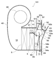
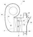
- FIG. 1 is a schematic diagram showing an example of a vehicle air conditioner according to the present embodiment.
- the vehicle air conditioner 100 forms an air flow path 10, and on the downstream side of the air flow path 10, a defroster opening 12 connected to a defroster air outlet (not shown), a vent air outlet (not)
- a case 40 having a vent opening 13 connected to an illustration (not shown) and a foot opening 14 connected to a foot outlet (not shown), a blower 30 for forming an air flow 31 in the air flow path 10, and an air flow path 10, the evaporator 5 disposed in the downstream side of the evaporator 5, the heater 6 always passing the air flow 32 when the blower 30 is in operation, and the bypass flow bypassing the heater 6.
- bypass door 21 Passes through the path 11, the bypass door 21 that opens and closes the bypass passage 11, the bypass control means (not shown) that controls the opening and closing of the bypass door 21, the defroster opening 12, the vent opening 13, and the foot opening 14. That comprises outlet control means for controlling the distribution of air volume (not shown).
- the case 40 has an air flow path 10 therein, and at least the evaporator 5 and the heater 6 are arranged in the air flow path 10 to send HVAC air whose temperature is adjusted into the vehicle interior. This is the case.
- An outside air inlet (not shown) and an inside air inlet (not shown) are provided on the most upstream side of the air flow path 10.
- the outside air inlet and the inside air inlet are selectively opened and closed by switching an intake door (not shown), and the air introduced into the air flow path 10 can be selected as outside air, inside air, or inside / outside air mixed air. ing.
- the blower 30 has a drive motor and a fan, and rotates the fan by driving the drive motor and sucks air to form an air flow 31 in the air flow path 10.
- the air flow 31 passes through the evaporator 5 after passing through a filter (not shown).
- the vehicle air conditioner 100 includes a refrigeration cycle 1.
- the refrigeration cycle 1 includes at least a compressor 2, an outdoor heat exchanger 3, a refrigerant expansion means 4, and an evaporator 5.
- the compressor (compressor) 2 receives the driving force from the engine or the driving force of a motor driven by electric power, compresses the low-temperature and low-pressure vaporized refrigerant into a high-temperature and high-pressure vaporized refrigerant. To do.
- the compressor 2 is preferably a variable capacity type or an electric type.
- the variable capacity compressor is a compressor that changes the capacity of refrigerant to be discharged.
- the type of the variable capacity compressor is not particularly limited, and examples thereof include a swash plate type, a wobble type, a vane type, and a scroll type.
- EDC Electric Driver Compressor
- An electric compressor is a compressor that sucks, compresses, and discharges a refrigerant by being driven by an electric motor. Therefore, since the rotation speed is not affected by the engine speed, the temperature of the evaporator 5 can be adjusted with higher accuracy.
- an electric compressor may be mounted on a hybrid vehicle (HEV, Hybrid Electric Vehicle) because the engine may stop during operation.
- an electric vehicle Electric Vehicle
- an electric compressor is mounted.
- the outdoor heat exchanger 3 exchanges heat between the refrigerant flowing inside and the outside air or running air taken in by a cooling fan (not shown) disposed in the vicinity of the outdoor heat exchanger 3.
- the refrigerant expansion means 4 converts the high-temperature and high-pressure liquefied refrigerant into a low-temperature and low-pressure gas-liquid mixed refrigerant by a throttling action.
- the evaporator (evaporator) 5 exchanges heat between the refrigerant flowing inside and the air flow 31 passing through the evaporator 5.
- the refrigeration cycle 1 shown in FIG. 1 operates as follows.
- the high-temperature and high-pressure vaporized refrigerant discharged from the compressor 2 flows into the outdoor heat exchanger 3.
- the refrigerant exchanges heat with outside air or traveling wind passing through the outdoor heat exchanger 3, and becomes a high-temperature and high-pressure liquefied refrigerant.
- this refrigerant passes through the refrigerant expansion means 4, it becomes a low-temperature low-pressure gas-liquid mixed refrigerant and flows into the evaporator 5.
- the refrigerant exchanges heat with the air flow 31 passing through the evaporator 5 to become a low-temperature and low-pressure vaporized refrigerant and is sucked into the compressor 2.
- the air flow 32 that has passed through the evaporator 5 is cooled and dehumidified air, and is used for cooling or dehumidifying the passenger compartment.
- the air flow 32 that has passed through the evaporator 5 passes through the heater 6.
- the heater (heater core) 6 reheats the air of the air flow 32 that has passed through the evaporator 5.
- the heater 6 is, for example, a hot water heater using engine cooling water heated by engine exhaust heat, an electric heating heater having a heating element, or a radiator using hot gas of a heat pump cycle. .
- a known heating wire such as a PTC (Positive Temperature Coefficient) element is used as a heating element.
- the air flow 32 always passes through the heater 6. That is, there is no mix door upstream of the heater 6. Therefore, the evaporator 5 and the heater 6 can be brought close to each other, and the vehicle air conditioner 100 can be reduced in size and weight. Furthermore, as described in paragraph [0044], since the air of a predetermined temperature can be created by having temperature control means (not shown) for controlling the temperature of the heater 6, conventional vehicle air conditioners Thus, a large-capacity mix space for mixing the warm air reheated after passing through the heater and the cool air not passing through the heater is unnecessary, and the case 40 can be further miniaturized.
- the bypass channel 11 is a part of the air channel 10 and is a channel that bypasses the heater 6.
- the bypass channel 11 is opened and closed by a bypass door 21. Adjustment of the opening degree of the bypass door 21 is performed by a bypass control means (not shown).
- the bypass control means has a drive unit (not shown) that drives the bypass door 21 and a control unit (not shown) that controls the drive unit.
- the drive unit is, for example, a servo motor.
- the control unit is, for example, an ECU (Electronic Control Unit) including a CPU as a central processing unit.
- the ECU receives a blowing mode or set temperature signal from an operation panel (not shown) performed by the occupant, or sensor signals from various sensors such as an outside air temperature sensor, a vehicle interior temperature sensor, or a solar radiation amount sensor, and determines the blowing mode. And the target position of the bypass door 21 is calculated and an output signal is transmitted. Then, the servo motor adjusts the opening degree of the bypass door 21 by rotationally displacing to a predetermined angle based on the output signal.
- a defroster (DEF) opening 12, a vent (VENT) opening 13, and a foot (FOOT) opening 14 are provided on the downstream side of the air flow path 10.
- the DEF opening 12 is connected to a DEF outlet (not shown) provided in the vehicle interior via a DEF duct (not shown).
- the DEF outlet is an outlet for blowing wind toward the inner surface of the window glass in front of the vehicle.
- the VENT opening 13 is also called a FACE opening, and is connected to a VENT outlet (not shown) provided in the vehicle compartment via a VENT duct (not shown).
- the VENT outlet is an outlet for blowing wind toward the upper body of the occupant.
- the VENT air outlet usually has a center vent air outlet provided at the center in the vehicle width direction and side vent air outlets provided on the left and right in the vehicle width direction.
- the FOOT opening 14 is connected to a FOOT outlet (not shown) provided in the vehicle compartment via a FOOT duct (not shown).
- the FOOT air outlet is an air outlet for blowing out wind toward the feet of the passenger.
- the DEF opening 12, the VENT opening 13, or the FOOT opening 14 are opened and closed by the DEF door 22, the VENT door 23, or the FOOT door 24, respectively.
- the type of the DEF door 22, the VENT door 23, or the FOOT door 24 is a plate door in FIG. This embodiment is not limited to the type of door.
- the type of door is, for example, a film door, a rotary door, a slide door, or a butterfly door in addition to a plate door. Adjustment of the opening degree of the DEF door 22, the VENT door 23, or the FOOT door 24 is performed by an outlet control means (not shown).
- the air outlet control means controls the distribution of the air volume passing through each opening according to the passenger's request or the temperature distribution in the passenger compartment.
- the outlet control means has the same basic configuration as the bypass control means. That is, the ECU receives a blowing mode or set temperature signal from an operation panel (not shown) performed by the occupant or sensor signals from various sensors, calculates the blowing mode and calculates the target position of the bypass door 21 and outputs it. Send a signal. Based on the output signal, the air outlet control means rotationally displaces a servo motor (not shown) that drives the DEF door 22, the VENT door 23, or the FOOT door 24 to a predetermined angle, whereby the DEF door 22, The opening degree of the VENT door 23 or the FOOT door 24 is adjusted.
- the opening degree of the DEF door 22, the VENT door 23, or the FOOT door 24 may be individually controlled by a servo motor provided in each door, or may be simultaneously controlled by one servo motor.
- FIG. 2 is a schematic diagram showing an example of a link mechanism.
- the vehicle air conditioner 101 preferably further includes one link mechanism 50 that links the bypass control means and the outlet control means.
- the link mechanism 50 By controlling the bypass control means and the outlet control means with one link mechanism 50, the number of parts can be reduced.
- a main link 55 connected to a servo motor 60 as a drive source via a rod 65 as a transmission means, and a bypass door opening / closing lever 51a fixed to the shaft portion R1 of the bypass door 21.
- the link mechanism 50 should just be able to make a bypass control means and an air outlet control means interlock
- the blowing mode is, for example, a DEF mode in which the DEF opening 12 mainly opens, a VENT mode in which the VENT opening 13 mainly opens, a FOOT mode in which the FOOT opening 14 mainly opens, the VENT opening 13 and the FOOT opening.
- 14 is a bi-level mode (B / L mode) in which both open, or a differential / foot mode (D / F mode) in which both the DEF opening 12 and the FOOT opening 14 are open.
- the air flow 31 passes through the evaporator 5 and becomes a cooled and dehumidified air flow 32.
- the air flow 32 is only the air flow 33 that has passed through the heater 6 when the bypass flow path 11 is closed, and the air flow 33 that has passed through the heater 6 and the bypass flow path 11 when the bypass flow path 11 is open. It is divided into an air flow 34 that has passed.
- the air flow 33 and the air flow 34 are sent to the DEF opening 12, the VENT opening 13, or the FOOT opening 14 depending on the blowing mode, and are blown into the vehicle interior.
- a temperature control means for controlling the temperature of the evaporator 5 and a temperature control means (not shown) for controlling the temperature of the heater 6 are provided. It is preferable to have.
- the temperature adjustment of the air blown into the passenger compartment can be performed without using the air mix door. 6 can be performed by adjusting each temperature.
- the temperature control means of the evaporator 5 is preferably a control device for the compressor 2, for example.
- the amount of heat absorbed can be controlled by adjusting the capacity of the refrigerant flowing into the evaporator 5 without using complicated control means.
- the temperature control means of the heater 6 may be, for example, a flow rate control valve (not shown) provided upstream of the heater 6 in the engine cooling water flow path. preferable.
- the flow rate control valve can control the temperature of the heater 6 by controlling the flow rate of the hot water flowing inside the heater 6.
- the temperature control means of the heater 6 is, for example, a pulse width modulation (PWM) control device.
- PWM pulse width modulation
- the PWM control device can control the temperature of the heater 6 by controlling the amount of heat generated by the heating element.
- the temperature control means of the heater 6 is preferably a control device of the compressor 2, for example.
- the capacity of the refrigerant flowing into the radiator 7 can be adjusted, and the temperature of the radiator 7 can be controlled. In this way, by using a variable capacity or electric compressor or an electric heating heater, complicated control is unnecessary, and the temperature of the air blown into the passenger compartment more easily and accurately. Adjustments can be made.
- FIG. 3 is a schematic diagram showing a modification of the vehicle air conditioner according to the present embodiment.
- the vehicle air conditioner 100a shown in FIG. 3 has a configuration in which a heat pump cycle radiator 7 is used as a heater.
- the heater is the heat pump cycle radiator 7, and the heat pump cycle compressor 2 including the radiator 7 may be a variable capacity type or an electric type. preferable.
- an electric heating type heater 6 may be used as an auxiliary heater if necessary.
- the heater 6 showed the form which is an electric heating type, it can change into a warm water type.
- the refrigeration cycle 1a shown in FIG. 3 includes at least the compressor 2, the outdoor heat exchanger 3, the refrigerant expansion means 4, the evaporator 5, the radiator 7, the first switching valve 9a, and the second switching valve. 9b and a four-way valve 8 are provided.
- the compressor 2 is a variable capacity or electric compressor.
- the outdoor heat exchanger 3, the refrigerant expansion means 4, and the evaporator 5 are the same as those described as the constituent elements of the refrigeration cycle 1 shown in FIG.
- the 1st switching valve 9a is arrange
- the 2nd switching valve 9b is arrange
- the four-way valve 8 switches the supply direction of the refrigerant discharged from the compressor 2 and the suction direction of the refrigerant sucked into the compressor 2.
- the temperature of the air blown into the passenger compartment is adjusted as follows.
- the four-way valve 8 is set as shown by the solid line in FIG. Further, the refrigerant flow path is switched to a flow path between the refrigerant expansion means 4 and the evaporator 5 by the first switching valve 9a, and the refrigerant flow path is switched between the evaporator 5 and the compressor 2 by the second switching valve 9b. Switch to the flow path that circulates between. Then, the high-temperature and high-pressure vaporized refrigerant discharged from the compressor 2 flows in the direction of arrow F and flows into the outdoor heat exchanger 3. Here, the refrigerant exchanges heat with outside air or traveling wind passing through the outdoor heat exchanger 3, and becomes a high-temperature and high-pressure liquefied refrigerant.
- this refrigerant passes through the refrigerant expansion means 4, it becomes a low-temperature low-pressure gas-liquid mixed refrigerant and flows into the evaporator 5.
- the refrigerant exchanges heat with the air flow 31 passing through the evaporator 5 to become a low-temperature and low-pressure vaporized refrigerant and is sucked into the compressor 2.
- the flow rate of the refrigerant flowing into the evaporator 5 is adjusted by the variable capacity or electric compressor 2.
- the air flow 32 that has passed through the evaporator 5 becomes cold air whose temperature is adjusted, and is used for cooling the passenger compartment.
- the four-way valve 8 is set as shown by the dotted line in FIG. Furthermore, the second switching valve 9b switches the refrigerant flow path to a flow path that circulates between the compressor 2 and the radiator 7, and the first switching valve 9a switches the refrigerant flow path between the radiator 7 and the refrigerant expansion means 4. Switch to the flow path that circulates between. Then, the high-temperature and high-pressure liquefied refrigerant discharged from the compressor 2 flows in the direction of the arrow F and is supplied to the radiator 7. Here, the refrigerant exchanges heat with the air flow 32 passing through the radiator 7 and becomes a high-temperature and high-pressure liquefied refrigerant.
- this refrigerant passes through the refrigerant expansion means 4, it becomes a low-temperature and low-pressure gas-liquid mixed refrigerant and flows into the outdoor heat exchanger 3.
- the refrigerant exchanges heat with the outside air or traveling wind passing through the outdoor heat exchanger 3 to become a refrigerant in a vaporized state at low temperature and low pressure, and is sucked into the compressor 2.
- the flow rate of the refrigerant flowing into the radiator 7 is adjusted by the variable capacity or electric compressor 2.
- the air flow 33 that has passed through the radiator 7 becomes warm air whose temperature is adjusted, and is further warmed by the heater 6 as necessary, and is used for heating the passenger compartment.
- a variable displacement or electric compressor complicated control is unnecessary, and the temperature of the air blown into the vehicle compartment can be adjusted more easily and accurately.
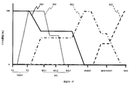
- FIG. 4 is a diagram showing opening patterns of the DEF door, the VENT door, the FOOT door, and the bypass door in the vehicle air conditioner according to the present embodiment.
- symbol D21 indicates the opening degree of the bypass door
- symbol D22 indicates the opening degree of the DEF door
- symbol D23 indicates the opening degree of the VENT door
- symbol D24 indicates the pattern of the opening degree of the FOOT door 24.
- FIG. 5 is a schematic diagram illustrating an example of a vehicle air conditioner according to the present embodiment, and is a diagram for explaining the B / L mode.
- the B / L mode is, for example, when the occupant is requesting head cold foot heat.
- the outlet control means outputs a signal for closing the DEF opening 12 and opening the VENT opening 13 and the FOOT opening 14.
- the opening degree D22 of the DEF door is 0% (fully closed).
- the opening D23 of the VENT door is preferably more than 0% and not more than 100%, and more preferably 40 to 60%.
- the opening D24 of the FOOT door is preferably more than 0% and not more than 100%, and more preferably 40 to 60%.
- a bypass control means (not shown) outputs a signal for opening the bypass flow path 11.
- the opening D21 of the bypass door is preferably more than 0% and not more than 100%, and more preferably 50 to 100%.
- the B / L mode preferably has a mode in which the opening degree D21 of the bypass door is changed, such as a B / L1 mode, a B / L2 mode, or a B / L3 mode.
- the opening degree D21 of the bypass door is almost fully opened. Accordingly, it is possible to blow out cold air from the VENT outlet and blow out hot air from the FOOT outlet to further increase the temperature difference between the upper and lower sides of the passenger compartment.
- the B / L1 mode is a mode that is selected when the sunlight is strong, for example, in winter.
- the opening D21 of the bypass door is made smaller than that in the B / L1 mode.
- the B / L2 mode is a mode that is selected when the temperature difference between the upper and lower sides of the passenger compartment may be smaller than that in the B / L1 mode.
- the opening D21 of the bypass door is made smaller than in the B / L2 mode.
- the B / L3 mode is a mode that is selected when the temperature difference between the upper and lower sides of the passenger compartment is not so necessary.
- the opening D21 of the bypass door in each mode is not particularly limited.
- the opening D21 of the bypass door is, for example, more than 70% and 100% or less
- the bypass door in the B / L2 mode, the bypass door The door opening D21 is, for example, more than 30% and 70% or less.
- the opening D21 of the bypass door is, for example, more than 0% and 30% or less.
- the relative positional relationship between the heater 6 and the bypass passage 11 is closer to the heater 6 than the foot opening 14. It is preferable that the bypass channel 11 is disposed far away.
- the air flow 34 that has passed through the bypass channel 11 is more reliably supplied to the VENT opening 13, and the air flow 33 that has passed the heater 6 is more reliably supplied to the FOOT opening 14. Can blow. And there is no possibility of reducing the temperature difference between the wind blown from the VENT outlet and the wind blown from the FOOT outlet.
- FIG. 6 is a schematic diagram illustrating an example of a vehicle air conditioner according to the present embodiment, and is a diagram for explaining a DEF mode.
- the outlet control means outputs a signal for opening the DEF opening 12 and closing the VENT opening 13 and the FOOT opening 14.
- the opening degree D22 of the DEF door is 100% (fully open).
- the opening D23 of the VENT door and the opening D24 of the FOOT door are 0% (fully closed).
- a bypass control means (not shown) outputs a signal for closing the bypass flow path 11. As shown in FIG.
- the opening D21 of the bypass door is 0% (fully closed).
- heating as hot air is performed as shown in FIG.
- the air flow 33 that has passed through the vessel 6 is blown to the DEF opening 12. Then, warm air can be blown out from the DEF outlet to prevent the windshield from fogging.
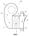
- FIG. 7 is a schematic diagram illustrating an example of a vehicle air conditioner according to the present embodiment, and is a diagram for explaining a VENT mode.
- the outlet control means outputs a signal for closing the DEF opening 12 and the FOOT opening 14 and opening the VENT opening 13.
- the opening degree D22 of the DEF door and the opening degree D24 of the FOOT door are 0% (fully closed).
- the opening D23 of the VENT door is 100% (fully open).
- a bypass control means (not shown) outputs a signal for closing the bypass flow path 11. As shown in the V1 mode of FIG.
- the opening D21 of the bypass door is 0% (fully closed).
- heating as hot air is performed as shown in FIG.
- the air flow 33 that has passed through the vessel 6 is blown to the VENT opening 13. And warm air can be blown out toward a passenger
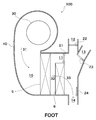
- FIG. 8 is a schematic diagram illustrating an example of a vehicle air conditioner according to the present embodiment, and is a diagram for explaining a FOOT mode.
- FOOT mode for example, the occupant is requesting wind toward his / her feet.
- the outlet control means outputs a signal for closing the DEF opening 12 and the VENT opening 13 and opening the FOOT opening 14.
- the opening degree D22 of the DEF door and the opening degree D23 of the VENT door are 0% (fully closed).
- the opening degree D24 of the FOOT door is 100% (fully open).
- a bypass control means (not shown) outputs a signal for closing the bypass flow path 11. As shown in FIG.
- the opening D21 of the bypass door is 0% (fully closed).
- heating as hot air is performed as shown in FIG.
- the air flow 33 that has passed through the vessel 6 is blown to the FOOT opening 14. And a warm air can be blown out from a FOOT blower outlet, and a passenger
- FIG. 9 is a schematic diagram illustrating an example of a vehicle air conditioner according to the present embodiment, and is a diagram for explaining a DEF / FOOT mode.
- DEF / FOOT D / F
- the outlet control means outputs a signal for opening the DEF opening 12 and the FOOT opening 14 and closing the VENT opening 13.
- the opening degree D22 of the DEF door is preferably more than 0% and not more than 100%, and more preferably 40-60%.
- the opening D23 of the VENT door is 0% (fully closed).
- the opening D24 of the FOOT door is preferably more than 0% and not more than 100%, and more preferably 40 to 60%.
- a bypass control means (not shown) outputs a signal for closing the bypass flow path 11.
- the opening D21 of the bypass door is 0% (fully closed).
- heating as warm air is performed as shown in FIG.
- the air flow 33 that has passed through the vessel 6 is blown to the DEF opening 12 and the FOOT opening 14. Then, warm air is blown out from the DEF air outlet to prevent the windshield from being fogged, and hot air is blown out from the FOOT air outlet to warm the feet of the passenger.
- FIG. 10 is a schematic diagram illustrating an example of a vehicle air conditioner according to the present embodiment, and is a diagram for explaining cooling or blowing.
- FIG. 10 shows a case where the blowing mode is the VENT mode.
- the heater 6 is not operating, for example, when the occupant is requesting cooling or when only air is required.
- the bypass control means preferably outputs a signal for opening the bypass flow path 11.
- the opening D21 of the bypass door is preferably more than 0% and not more than 100%. More preferably, it is set to 100%. Thereby, at the time of cooling or blowing, the air resistance can be reduced and the amount of blowing can be increased.
- the opening degree D21 of the bypass door is 0 when the heater 6 is not operating, as in the V2 mode. It is preferable that it exceeds 100% and is 100% or less. More preferably, it is 100%.
- FIG. 11 is a schematic diagram showing a modification of the vehicle air conditioner according to the embodiment.
- FIGS. 1 to 3 and FIGS. 5 to 10 show the form in which the evaporator 5 and the heater 6 are arranged in parallel, but in this embodiment, the heater 6 is inclined and arranged as shown in FIG. Also good. By arranging in this way, the case 40 can be further downsized.
- the bypass door 21 is provided above the heater 6 or the radiator 7, but the bypass door 21 bypasses the heater 6 or the radiator 7. Can be provided as long as the desired upper and lower temperature difference can be given when the channel is opened and opened. For example, it may be disposed below or on the side of the heater 6 or the radiator 7.
Landscapes
- Physics & Mathematics (AREA)
- Thermal Sciences (AREA)
- Engineering & Computer Science (AREA)
- Mechanical Engineering (AREA)
- Air-Conditioning For Vehicles (AREA)
Abstract
本発明の目的は、小型化及び軽量化ができ、かつ、上下の温度差の調整を容易に行うことができる車両用空調装置を提供することである。本発明に係る車両用空調装置100は、空気流路10を形成し、空気流路の下流側に、デフロスタ吹出口に接続されるデフロスタ開口部12、ベント吹出口に接続されるベント開口部13及びフット吹出口に接続されるフット開口部14を有するケース40と、空気流路に空気流れ31を形成する送風機30と、空気流路内に配置される蒸発器5と、蒸発器よりも下流側に配置され、送風機が作動中には、空気流れ32を常に通過させる加熱器6と、加熱器を迂回するバイパス流路11と、バイパス流路を開閉するバイパスドア21と、バイパスドアの開閉を制御するバイパス制御手段と、デフロスタ開口部、ベント開口部及びフット開口部を通過する風量の配分を制御する吹出口制御手段と、を備える。
Description
本発明は、吹出口から車室内へ吹き出す送風空気の温度を、適切な温度にすることができる車両用空調装置に関する。
車両用空調装置は、その機能として、任意の吹出口から空気を吹き出すこと又は所望する吹出口から調和された空気を吹き出すことのほか、吹出口に応じた適切な温度の空気を吹き出すことが求められる。また、一般的な要求事項として、小型化、軽量化及び温度調整の容易化がある。
車両用空調装置は、一般に、送風空気を形成する送風機(ブロワ)と、冷凍サイクルの一部を構成し、低温の冷媒と送風空気との間で熱交換して冷風を形成する蒸発器(エバポレータ)と、蒸発器の下流に配置され、蒸発器で形成された冷風を再加熱して温風を形成する加熱器(ヒーターコア)とを備える。加熱器には、エンジンの排熱によって温められた温水が流れており、定常状態にあっては約90℃で一定している。従来の車両用空調装置では、蒸発器を通過した冷風のうち、加熱器を通過して再加熱される空気の比率を、温調制御手段(ミックスドア)の開度で制御し、この加熱器を通過して再加熱された温風と加熱器を通過しない冷風とを、混合室(ミックス空間)で均一に混合して、所定の温度の空気を作り出している。このように、ミックスドアは、蒸発器を通過した空気を、加熱器へ、0~100%の範囲において配風することを制御できる必要がある。
ところで、車両用空調装置には、バイレベルモードのときに、乗員の上半身側に設けられたベント吹出口から吹き出される風と乗員の足元側に設けられたフット吹出口から吹き出される風とに温度差を付与し、ベント吹出口から吹き出される風の温度を、フット吹出口から吹き出される風の温度よりも相対的に低くする要請(車室内の上下で温度差をつける要請)がある。
車室内の上下で温度差をつけることができる車両用空調装置が提案されている(例えば、特許文献1を参照。)。特許文献1には、加熱器を迂回した冷風を、フェイス開口部方向に通過させる補助冷風バイパス通路を設け、フェイス開口部が開く吹出モード時には補助冷風バイパス通路を開とし、フェイス開口部を閉じる吹出モード時には補助冷風バイパス通路を閉とすることで、乗員の足元から吹き出す空気の温度を高く設定しても、乗員の頭胸部には、比較的涼しい冷風を送ることができる技術が開示されている。
特許文献1をはじめとする車両用空調装置では、蒸発器と加熱器との間にミックスドアを配置している。ミックスドアの配置の別形態として、ミックスドアを、蒸発器と加熱器との間ではなく、加熱器の下流に配置する構成が考えられる。しかし、この構成では、蒸発器を通過した空気が加熱器に接するため、最大冷房時、すなわち加熱器へ、全く配風しないというモードにすることができず、冷風が加熱器の熱を吸収して、冷房能力が阻害されるおそれがある。よって、従来の車両用空調装置では、この別形態を採用せず、ミックスドアは、加熱器の前面を塞ぐことができるように、蒸発器と加熱器との間に配置する必要があった。さらに、温風と冷風とを十分に混合し、温度調整を精度よく行うためには、加熱器の下流に設けるミックス空間をできるだけ大容量とすることが必要であった。これらのことは、車両用空調装置の小型化及び軽量化を困難にしていた。
さらに、蒸発器と加熱器との間に配置したミックスドアによって温度を調整すること及びバイレベルモードで吹き出すときに上下の温度差を付与することの両立は、ミックスドアによる配風比率の調整及び空調装置のケーシング形状の設定にあたり繊細な調整(チューニング)が必要で、開発工数がかかるという問題があった。そのうえ、所望する上下温度差が付与できないおそれがあった。
本発明の目的は、小型化及び軽量化ができ、かつ、上下の温度差の調整を容易に行うことができる車両用空調装置を提供することである。
本発明に係る車両用空調装置は、空気流路を形成し、該空気流路の下流側に、デフロスタ吹出口に接続されるデフロスタ開口部、ベント吹出口に接続されるベント開口部及びフット吹出口に接続されるフット開口部を有するケースと、前記空気流路に空気流れを形成する送風機と、前記空気流路内に配置される蒸発器と、該蒸発器よりも下流側に配置され、前記送風機が作動中には、前記空気流れが常に通過する加熱器と、該加熱器を迂回するバイパス流路と、該バイパス流路を開閉するバイパスドアと、該バイパスドアの開閉を制御するバイパス制御手段と、前記デフロスタ開口部、前記ベント開口部及び前記フット開口部を通過する風量の配分を制御する吹出口制御手段と、を備える。
本発明に係る車両用空調装置では、前記加熱器と前記バイパス流路との相対的な位置関係が、前記フット開口部に対して、前記加熱器を近く、前記バイパス流路を遠く配置していることが好ましい。車室内の上下の温度差をより確実に付与することができる。
本発明に係る車両用空調装置では、前記加熱器が作動し、かつ、前記ベント開口部及び前記フット開口部の両方が開口するバイレベルモードのとき、前記バイパス制御手段が、前記バイパス流路を開とする信号を出力することが好ましい。暖房時、バイレベルモードにおいて、車室内の上下の温度差をより確実に付与することができる。
本発明に係る車両用空調装置では、前記加熱器が作動し、かつ、前記デフロスタ開口部が開口するデフロスタモード、前記ベント開口部が開口するベントモード、前記フット開口部が開口するフットモード又は前記デフロスタ開口部及び前記フット開口部の両方が開口するデフ/フットモードのとき、前記バイパス制御手段が、前記バイパス流路を閉とする信号を出力することが好ましい。暖房時、デフロスタモード、ベントモード、フットモード及びデフ/フットモードにおいて、車室内を効率的に暖めることができる。
本発明に係る車両用空調装置では、前記加熱器が作動していないとき、前記バイパス制御手段が、前記バイパス流路を開とする信号を出力することが好ましい。冷房時又は送風時、空気抵抗を低減して、送風量の増加を図ることができる。
本発明に係る車両用空調装置では、前記バイパス制御手段と前記吹出口制御手段とを連動させる一つのリンク機構を更に有することが好ましい。部品の点数を削減することができる。
本発明に係る車両用空調装置では、前記加熱器が、電気発熱式であることが好ましい。加熱器での発熱量を調整し、所定の温度の空気を作り出すことができる。
本発明に係る車両用空調装置では、前記加熱器が、ヒートポンプサイクルの放熱器であり、かつ、該放熱器を含むヒートポンプサイクルの圧縮機が、可変容量式又は電動式であることが好ましい。冷媒の循環量を制御することで加熱器での発熱量を調整し、所定の温度の空気を作り出すことができる。
本発明に係る車両用空調装置では、前記蒸発器を含む冷凍サイクルの圧縮機が、可変容量式又は電動式であることが好ましい。冷媒の循環量を制御することで蒸発器での吸熱量を調整し、所定の温度の空気を作り出すことができる。
本発明は、小型化及び軽量化ができ、かつ、上下の温度差の調整を容易に行うことができる車両用空調装置を提供することができる。
以下、図面を参照して本発明の一態様を説明する。以下に説明する実施形態は本発明の実施例であり、本発明は、以下の実施形態に制限されるものではない。なお、本明細書及び図面において符号が同じ構成要素は、相互に同一のものを示すものとする。本発明の効果を奏する限り、種々の形態変更をしてもよい。
図1は、本実施形態に係る車両用空調装置の一例を示す概略図である。本実施形態に係る車両用空調装置100は、空気流路10を形成し、空気流路10の下流側に、デフロスタ吹出口(不図示)に接続されるデフロスタ開口部12、ベント吹出口(不図示)に接続されるベント開口部13及びフット吹出口(不図示)に接続されるフット開口部14を有するケース40と、空気流路10に空気流れ31を形成する送風機30と、空気流路10内に配置される蒸発器5と、蒸発器5よりも下流側に配置され、送風機30が作動中には、空気流れ32を常に通過させる加熱器6と、加熱器6を迂回するバイパス流路11と、バイパス流路11を開閉するバイパスドア21と、バイパスドア21の開閉を制御するバイパス制御手段(不図示)と、デフロスタ開口部12、ベント開口部13及びフット開口部14を通過する風量の配分を制御する吹出口制御手段(不図示)と、を備える。
ケース40は、その内部に空気流路10を有し、空気流路10に、少なくとも、蒸発器5と、加熱器6とを配置して、車室内に温度調整した送風空気を送るためのHVACのケースである。
空気流路10の最上流側には、外気取入れ口(不図示)と内気取入れ口(不図示)とが設けられている。外気取入れ口と内気取入れ口とは、インテークドア(不図示)の切り替えによって、選択的に開閉され、空気流路10に導入する空気を、外気、内気又は内外気混合空気に選択できるようになっている。
送風機(ブロワ)30は、駆動用モータとファンとを有し、駆動用モータの駆動によってファンを回転させて、空気を吸入することで、空気流路10に空気流れ31を形成する。空気流れ31は、フィルタ(不図示)を通過した後、蒸発器5を通過する。
車両用空調装置100は、冷凍サイクル1を備える。冷凍サイクル1は、少なくとも、圧縮機2と、室外熱交換器3と、冷媒膨張手段4と、蒸発器5とを有する。
圧縮機(コンプレッサ)2は、エンジンからの駆動力を受けて、又は電力によって駆動するモータの駆動力を受けて、低温低圧の気化状態の冷媒を圧縮して、高温高圧の気化状態の冷媒にするものである。
本実施形態に係る車両用空調装置100では、圧縮機2が、可変容量式又は電動式であることが好ましい。可変容量式圧縮機は、吐出する冷媒の容量を変化させる圧縮機である。可変容量式圧縮機の種類は、特に限定されず、例えば、斜板形、ワッブル形、ベーン形、スクロール形である。可変容量式圧縮機を用いることで、蒸発器5の温度を精度よく調整することができる。電動式圧縮機(EDC,Electrical Driver Compressor)は、電気モータの駆動を受けて冷媒の吸入、圧縮及び吐出を行う圧縮機である。よって、その回転数はエンジンの速度に影響を受けないため、蒸発器5の温度をより高い精度で調整することができる。なお、ハイブリッド車(HEV,Hybrid Electrical Vehicle)は、エンジンが運転時に停止することがあるため、電動式圧縮機が搭載されることがある。また、電気自動車(EV,Electrical Vehicle)は、そもそもエンジンをもたないため、電動式圧縮機が搭載される。
室外熱交換器3は、内部を流れる冷媒と、室外熱交換器3の近傍に配置された冷却ファン(不図示)によって取り込まれる外気又は走行風とを熱交換する。
冷媒膨張手段4は、高温高圧の液化状態の冷媒を、絞り作用によって、低温低圧の気液混合状態の冷媒とするものである。
蒸発器(エバポレータ)5は、内部を流れる冷媒と、蒸発器5を通過する空気流れ31とを熱交換する。
図1に示す冷凍サイクル1は、次のように作用する。圧縮機2から吐出した高温高圧の気化状態の冷媒は、室外熱交換器3に流入する。ここで、冷媒は、室外熱交換器3を通過する外気又は走行風と熱交換して、高温高圧の液化状態の冷媒となる。この冷媒は、冷媒膨張手段4を通過すると、低温低圧の気液混合状態の冷媒となり、蒸発器5に流入する。ここで、冷媒は、蒸発器5を通過する空気流れ31と熱交換して、低温低圧の気化状態の冷媒となり、圧縮機2に吸入される。この過程で、蒸発器5を通過した空気流れ32は、冷却除湿された空気となり、車室内の冷房又は除湿に利用される。
蒸発器5を通過した空気流れ32は、加熱器6を通過する。加熱器(ヒーターコア)6は、蒸発器5を通過した空気流れ32の空気を再加熱するものである。加熱器6は、例えば、エンジン排熱によって温められたエンジン冷却水を利用した温水式の加熱器、発熱素子を有する電気発熱式の加熱器、又はヒートポンプサイクルのホットガスを利用した放熱器である。電気発熱式の加熱器は、発熱素子として、PTC(Positive Temperature Coefficient)素子などの周知の電熱線が用いられる。
送風機30が作動中には、加熱器6には、常に空気流れ32が通過する。すなわち、加熱器6の上流には、ミックスドアが無い。よって、蒸発器5と加熱器6とを接近させることができ、車両用空調装置100の小型化及び軽量化が可能となる。さらに、段落[0044]に記載するように、加熱器6の温度を制御する温度制御手段(不図示)を有することで、所定の温度の空気を作り出すことができるので、従来の車両用空調装置のように加熱器を通過して再加熱された温風と加熱器を通過しない冷風とを混合する大容量のミックス空間は不要であり、ケース40の更なる小型化が可能となる。
バイパス流路11は、空気流路10の一部であり、加熱器6を迂回する流路である。バイパス流路11は、バイパスドア21によって開閉される。バイパスドア21の開度の調整は、バイパス制御手段(不図示)によって行われる。
バイパス制御手段(不図示)は、バイパスドア21を駆動する駆動部(不図示)と駆動部を制御する制御部(不図示)とを有する。駆動部は、例えば、サーボモータである。制御部は、例えば、中央演算処理装置としてのCPUを含むECU(Electronic Control Unit)である。ECUは、乗員が行う操作パネル(不図示)からの吹出モード若しくは設定温度の信号又は外気温度センサ、車室内温度センサ若しくは日射量センサなどの各種センサからのセンサ信号が入力され、吹出モードの決定及びバイパスドア21の目標位置を演算し、出力信号を発信する。そして、サーボモータは、この出力信号に基づいて、所定の角度まで回転変位することによって、バイパスドア21の開度を調整する。
空気流路10の下流側には、デフロスタ(DEF)開口部12、ベント(VENT)開口部13及びフット(FOOT)開口部14が設けられている。DEF開口部12は、DEFダクト(不図示)を介して、車室内に設けられたDEF吹出口(不図示)に接続される。DEF吹出口は、車両前方の窓ガラスの内面に向けて風を吹き出すための吹出口である。VENT開口部13は、FACE開口部とも呼ばれ、VENTダクト(不図示)を介して、車室内に設けられたVENT吹出口(不図示)に接続される。VENT吹出口は、乗員の上半身に向けて風を吹き出すための吹出口である。VENT吹出口は、通常、車幅方向の中央部に設けられたセンターベント吹出口と車幅方向の左右に設けられたサイドベント吹出口とを有する。FOOT開口部14は、FOOTダクト(不図示)を介して、車室内に設けられたFOOT吹出口(不図示)に接続されている。FOOT吹出口は、乗員の足元に向けて風を吹き出すための吹出口である。
DEF開口部12、VENT開口部13又はFOOT開口部14は、それぞれ、DEFドア22、VENTドア23又はFOOTドア24によって開閉される。DEFドア22、VENTドア23又はFOOTドア24の種類は、図1では、板ドアである。本実施形態はドアの種類に限定されない。ドアの種類は、板ドアの他、例えば、フィルムドア、ロータリードア、スライドドア、バタフライドアである。DEFドア22、VENTドア23又はFOOTドア24の開度の調整は、吹出口制御手段(不図示)によって行われる。
吹出口制御手段は、乗員の要求又は車室内の温度分布などに応じて、各開口部を通過する風量の配分を制御する。吹出口制御手段は、基本的な構成を、バイパス制御手段と同じくする。すなわち、ECUは、乗員が行う操作パネル(不図示)からの吹出モード若しくは設定温度の信号又は各種センサからのセンサ信号が入力され、吹出モードの決定やバイパスドア21の目標位置を演算し、出力信号を発信する。そして、吹出口制御手段は、この出力信号に基づいて、DEFドア22、VENTドア23又はFOOTドア24を駆動するサーボモータ(不図示)を所定の角度まで回転変位することによって、DEFドア22、VENTドア23又はFOOTドア24の開度を調整する。DEFドア22、VENTドア23又はFOOTドア24の開度は、各ドアにそれぞれ設けたサーボモータによって、別個に制御するか、又は1個のサーボモータによって、同時に制御してもよい。
図2は、リンク機構の一例を示す概略図である。本実施形態に係る車両用空調装置101では、バイパス制御手段と吹出口制御手段とを連動させる一つのリンク機構50を更に有することが好ましい。バイパス制御手段と吹出口制御手段とを一つのリンク機構50で制御することで、部品の点数を削減することができる。リンク機構50の一例としては、伝達手段としてのロッド65を介して、駆動源としてのサーボモータ60と連結されたメインリンク55と、バイパスドア21の軸部R1に固定されたバイパスドア開閉レバー51aと、DEFドア22の軸部R2に固定されたDEFドア開閉レバー52aと、VENTドア23の軸部R3に固定されたVENTドア開閉レバー53aと、FOOTドア24の軸部R4に固定されたFOOTドア開閉レバー54aと、各ドア開閉レバー51a,52a,53a,54a及びメインリンク55を連結するロッド51b,52b,53b,54bとを有する。そして、メインリンク55がサーボモータ60の駆動を受けて回動すると、バイパスドア21、DEFドア22、VENTドア23及びFOOTドア24が、連動して、それぞれ別個の制御手段を設けた形態と同様に、各モードに応じた開閉状態となる。なお、リンク機構50は、バイパス制御手段と吹出口制御手段とを連動させることができればよく、図2に示す形態に限定されない。
風量の配分例としては、次に示す吹出モードがある。吹出モードは、例えば、DEF開口部12が主に開口するDEFモード、VENT開口部13が主に開口するVENTモード、FOOT開口部14が主に開口するFOOTモード、VENT開口部13及びFOOT開口部14の両方が開口するバイレベルモード(B/Lモード)又はDEF開口部12及びFOOT開口部14の両方が開口するデフ/フットモード(D/Fモード)である。
次に、図1を用いて、車両用空調装置100の動作の概要を説明する。
送風機30が作動すると、空気流れ31は、蒸発器5を通過して、冷却除湿された空気流れ32となる。空気流れ32は、バイパス流路11が閉のときには、加熱器6を通過した空気流れ33だけとなり、バイパス流路11が開のときには、加熱器6を通過した空気流れ33とバイパス流路11を通過した空気流れ34とに分けられる。空気流れ33及び空気流れ34は、吹出モードに応じて、DEF開口部12、VENT開口部13又はFOOT開口部14に送られ、車室内に送風される。
本実施形態に係る車両用空調装置100では、蒸発器5の温度を制御する温度制御手段(不図示)若しくは加熱器6の温度を制御する温度制御手段(不図示)のいずれか一方又は両方を有することが好ましい。蒸発器5の温度制御手段又は加熱器6の温度制御手段の少なくともいずれかを有することで、車室内に送風される空気の温度調整は、エアミックスドアが無くても、蒸発器5及び加熱器6の各温度調整によって行うことができる。蒸発器5の温度制御手段は、例えば、圧縮機2の制御装置であることが好ましい。圧縮機2として、可変容量式又は電動式の圧縮機を用いることで、複雑な制御手段を用いることなく、蒸発器5に流入する冷媒の容量の調整し、吸熱量を制御することができる。加熱器6の温度制御手段は、加熱器6が温水式である場合には、例えば、エンジン冷却水の流路において、加熱器6の上流に設けた流量制御弁(不図示)であることが好ましい。流量制御弁は、加熱器6の内部を流れる温水の流量を制御して、加熱器6の温度を制御することができる。また、加熱器6が電気発熱式である場合、加熱器6の温度制御手段は、例えば、パルス幅変調(Pulse Width Modulation、PWM)制御装置であることが好ましい。PWM制御装置は、発熱素子の発熱量を制御して、加熱器6の温度を制御することができる。さらに、加熱器6がヒートポンプサイクルの放熱器である場合、加熱器6の温度制御手段は、例えば、圧縮機2の制御装置であることが好ましい。圧縮機2として、可変容量式又は電動式の圧縮機を用いることで、放熱器7に流入する冷媒の容量を調整し、放熱器7の温度を制御することができる。このように、可変容量式若しくは電動式の圧縮機又は電気発熱式の加熱器を用いることで、複雑な制御を不要とし、より簡単に、かつ、正確に、車室内に送風される空気の温度調整を行うことができる。
図3は、本実施形態に係る車両用空調装置の変形例を示す概略図である。図3に示す車両用空調装置100aは、加熱器としてヒートポンプサイクルの放熱器7を用いた形態である。本実施形態に係る車両用空調装置100aでは、加熱器が、ヒートポンプサイクルの放熱器7であり、かつ、放熱器7を含むヒートポンプサイクルの圧縮機2が、可変容量式又は電動式であることが好ましい。図3に示すように、ヒートポンプサイクルの放熱器に加えて、必要に応じて、補助ヒータとして電気発熱式の加熱器6を併用してもよい。なお、図3では、加熱器6が、電気発熱式である形態を示したが、温水式に変更することができる。
図3に示す冷凍サイクル1aは、少なくとも、圧縮機2と、室外熱交換器3と、冷媒膨張手段4と、蒸発器5と、放熱器7と、第一切替弁9aと、第二切替弁9bと、四方弁8とを備える。圧縮機2は、可変容量式又は電動式の圧縮機である。室外熱交換器3、冷媒膨張手段4及び蒸発器5は、図1に示す冷凍サイクル1の構成要素として説明したものと同様であるため、ここでは説明を省略する。第一切替弁9aは、冷媒膨張手段4と蒸発器5及び放熱器7との間に配置され、冷房時又は暖房時に応じて、冷媒流路の切り替えを行う。第二切替弁9bは、蒸発器5及び放熱器7と圧縮機2との間に配置され、冷房時又は暖房時に応じて、冷媒流路の切り替えを行う。四方弁8は、圧縮機2の吐出した冷媒の供給方向及び圧縮機2に吸入される冷媒の吸入方向の切り替えを行う。
図3に示す車両用空調装置100aでは、車室内に送風される空気の温度調整は次のように行う。
冷房の場合、四方弁8を、図3の実線のように設定する。さらに、第一切替弁9aによって、冷媒流路を冷媒膨張手段4と蒸発器5との間を流通する流路に切り替え、第二切替弁9bによって、冷媒流路を蒸発器5と圧縮機2との間を流通する流路に切り替える。すると、圧縮機2から吐出した高温高圧の気化状態の冷媒は、矢印Fの方向に流れて、室外熱交換器3に流入する。ここで、冷媒は、室外熱交換器3を通過する外気又は走行風と熱交換して、高温高圧の液化状態の冷媒となる。この冷媒は、冷媒膨張手段4を通過すると、低温低圧の気液混合状態の冷媒となり、蒸発器5に流入する。そして、冷媒は、蒸発器5を通過する空気流れ31と熱交換して、低温低圧の気化状態の冷媒となり、圧縮機2に吸入される。この過程で、蒸発器5に流入する冷媒の流量は、可変容量式又は電動式の圧縮機2によって調整される。すると、蒸発器5を通過した空気流れ32は、温度調整された冷風となり、車室内の冷房に利用される。
暖房の場合、四方弁8を、図3の点線のように設定する。さらに、第二切替弁9bによって、冷媒流路を圧縮機2と放熱器7との間を流通する流路に切り替え、第一切替弁9aによって、冷媒流路を放熱器7と冷媒膨張手段4との間を流通する流路に切り替える。すると、圧縮機2から吐出した高温高圧の液化状態の冷媒は、矢印Fの方向に流れて、放熱器7に供給される。ここで、冷媒は、放熱器7を通過する空気流れ32と熱交換して、高温高圧の液化状態の冷媒となる。この冷媒は、冷媒膨張手段4を通過すると、低温低圧の気液混合状態の冷媒となり、室外熱交換器3に流入する。そして、冷媒は、室外熱交換器3を通過する外気又は走行風と熱交換して、低温低圧の気化状態の冷媒となり、圧縮機2に吸入される。この過程で、放熱器7に流入する冷媒の流量は、可変容量式又は電動式の圧縮機2によって調整される。すると、放熱器7を通過した空気流れ33は、温度調整された温風となり、必要に応じて加熱器6で更に暖められて、車室内の暖房に利用される。このように、可変容量式又は電動式の圧縮機を用いることで、複雑な制御を不要とし、より簡単に、かつ、正確に、車室内に送風される空気の温度調整を行うことができる。
次に、各吹出モードにおける動作について、図4及び図5、図6、図7、図8、図9又は図10を用いて、説明する。図4は、本実施形態に係る車両用空調装置におけるDEFドア、VENTドア、FOOTドア及びバイパスドアの開度のパターンを示す図である。図4中、符号D21はバイパスドア21の開度、符号D22はDEFドア22の開度、符号D23はVENTドア23の開度及び符号D24はFOOTドア24の開度のパターンを示す。
(B/Lモード)
図5は、本実施形態に係る車両用空調装置の一例を示す概略図であり、B/Lモードを説明するための図である。B/Lモードのときは、例えば、乗員が頭寒足熱を要求しているときである。B/Lモードでは、吹出口制御手段が、DEF開口部12を閉、VENT開口部13及びFOOT開口部14を開とする信号を出力する。図4に示すように、DEFドアの開度D22は、0%(全閉)である。また、VENTドアの開度D23は、0%を超え100%以下とすることが好ましく、40~60%とすることがより好ましい。FOOTドアの開度D24は、0%を超え100%以下とすることが好ましく、40~60%とすることがより好ましい。加熱器6が作動する場合、バイパス制御手段(不図示)が、バイパス流路11を開とする信号を出力することが好ましい。図4に示すように、バイパスドアの開度D21は、0%を超え100%以下とすることが好ましく、50~100%とすることがより好ましい。バイパス流路11を開とすることで、図5に示すように、冷風であるバイパス流路11を通過した空気流れ34がVENT開口部13へ、温風である加熱器6を通過した空気流れ33がFOOT開口部14へ、それぞれ送風される。そして、VENT吹出口から吹き出される風の温度を、FOOT吹出口から吹き出される風の温度よりも相対的に低くすることができる。
図5は、本実施形態に係る車両用空調装置の一例を示す概略図であり、B/Lモードを説明するための図である。B/Lモードのときは、例えば、乗員が頭寒足熱を要求しているときである。B/Lモードでは、吹出口制御手段が、DEF開口部12を閉、VENT開口部13及びFOOT開口部14を開とする信号を出力する。図4に示すように、DEFドアの開度D22は、0%(全閉)である。また、VENTドアの開度D23は、0%を超え100%以下とすることが好ましく、40~60%とすることがより好ましい。FOOTドアの開度D24は、0%を超え100%以下とすることが好ましく、40~60%とすることがより好ましい。加熱器6が作動する場合、バイパス制御手段(不図示)が、バイパス流路11を開とする信号を出力することが好ましい。図4に示すように、バイパスドアの開度D21は、0%を超え100%以下とすることが好ましく、50~100%とすることがより好ましい。バイパス流路11を開とすることで、図5に示すように、冷風であるバイパス流路11を通過した空気流れ34がVENT開口部13へ、温風である加熱器6を通過した空気流れ33がFOOT開口部14へ、それぞれ送風される。そして、VENT吹出口から吹き出される風の温度を、FOOT吹出口から吹き出される風の温度よりも相対的に低くすることができる。
B/Lモードは、図4に示すように、B/L1モード、B/L2モード又はB/L3モードなどのパイパスドアの開度D21を変えたモードを有することが好ましい。B/L1モードでは、パイパスドアの開度D21をほぼ全開とする。これによって、VENT吹出口から冷風を吹き出し、FOOT吹出口から温風を吹き出して、車室内の上下の温度差をより大きくすることができる。このB/L1モードは、例えば、冬場で、日差しが強いときに選択されるモードである。B/L2モードでは、パイパスドアの開度D21をB/L1モードよりも小さくする。B/L2モードは、車室内の上下の温度差が、B/L1モードよりも小さくてよいときに選択されるモードである。B/L3モードでは、パイパスドアの開度D21をB/L2モードよりも更に小さくする。B/L3モードは、車室内の上下の温度差が、あまり必要ないときに選択されるモードである。このように、乗員の要求又は車室内の温度に応じて、VENT吹出口から吹き出される風とFOOT吹出口から吹き出される風との温度差の程度を調整することができる。各モードにおけるバイパスドアの開度D21は、特に限定されないが、例えば、B/L1モードでは、バイパスドアの開度D21を、例えば、70%を超え100%以下とし、B/L2モードでは、バイパスドアの開度D21を、例えば、30%を超え70%以下とし、B/L3モードでは、バイパスドアの開度D21を、例えば、0%を超え30%以下とする。
本実施形態に係る車両用空調装置100では、図5に示すように、加熱器6とバイパス流路11との相対的な位置関係が、フット開口部14に対して、加熱器6を近く、バイパス流路11を遠く配置していることが好ましい。このように配置することで、B/Lモードにおいて、バイパス流路11を通過した空気流れ34をVENT開口部13へ、加熱器6を通過した空気流れ33をFOOT開口部14へ、より確実に送風することができる。そして、VENT吹出口から吹き出される風とFOOT吹出口から吹き出される風との温度差を、小さくしてしまうおそれがない。
(DEFモード)
図6は、本実施形態に係る車両用空調装置の一例を示す概略図であり、DEFモードを説明するための図である。DEFモードのときは、例えば、フロントガラスの曇り止めを必要としているときである。DEFモードでは、吹出口制御手段が、DEF開口部12を開、VENT開口部13及びFOOT開口部14を閉とする信号を出力する。図4に示すように、DEFドアの開度D22は、100%(全開)である。また、VENTドアの開度D23及びFOOTドアの開度D24は、0%(全閉)である。さらに、加熱器6が作動する場合、バイパス制御手段(不図示)が、バイパス流路11を閉とする信号を出力する。図4に示すように、バイパスドアの開度D21は、0%(全閉)である。バイパスドアの開度D21、DEFドアの開度D22、VENTドアの開度D23及びFOOTドアの開度D24を、図4のようにすることで、図6に示すように、温風である加熱器6を通過した空気流れ33がDEF開口部12へ送風される。そして、DEF吹出口から温風を吹き出して、フロントガラスの曇り止めを行うことができる。
図6は、本実施形態に係る車両用空調装置の一例を示す概略図であり、DEFモードを説明するための図である。DEFモードのときは、例えば、フロントガラスの曇り止めを必要としているときである。DEFモードでは、吹出口制御手段が、DEF開口部12を開、VENT開口部13及びFOOT開口部14を閉とする信号を出力する。図4に示すように、DEFドアの開度D22は、100%(全開)である。また、VENTドアの開度D23及びFOOTドアの開度D24は、0%(全閉)である。さらに、加熱器6が作動する場合、バイパス制御手段(不図示)が、バイパス流路11を閉とする信号を出力する。図4に示すように、バイパスドアの開度D21は、0%(全閉)である。バイパスドアの開度D21、DEFドアの開度D22、VENTドアの開度D23及びFOOTドアの開度D24を、図4のようにすることで、図6に示すように、温風である加熱器6を通過した空気流れ33がDEF開口部12へ送風される。そして、DEF吹出口から温風を吹き出して、フロントガラスの曇り止めを行うことができる。
(VENTモード)
図7は、本実施形態に係る車両用空調装置の一例を示す概略図であり、VENTモードを説明するための図である。VENTモードのときは、例えば、乗員が上半身に向けて風を要求しているときである。VENTモードでは、吹出口制御手段が、DEF開口部12及びFOOT開口部14を閉、VENT開口部13を開とする信号を出力する。図4に示すように、DEFドアの開度D22及びFOOTドアの開度D24は、0%(全閉)である。また、VENTドアの開度D23は、100%(全開)である。さらに、加熱器6が作動する場合、バイパス制御手段(不図示)が、バイパス流路11を閉とする信号を出力する。図4のV1モードに示すように、バイパスドアの開度D21は、0%(全閉)である。バイパスドアの開度D21、DEFドアの開度D22、VENTドアの開度D23及びFOOTドアの開度D24を、図4のようにすることで、図7に示すように、温風である加熱器6を通過した空気流れ33がVENT開口部13へ送風される。そして、VENT吹出口から乗員の上半身に向けて温風を吹き出すことができる。
図7は、本実施形態に係る車両用空調装置の一例を示す概略図であり、VENTモードを説明するための図である。VENTモードのときは、例えば、乗員が上半身に向けて風を要求しているときである。VENTモードでは、吹出口制御手段が、DEF開口部12及びFOOT開口部14を閉、VENT開口部13を開とする信号を出力する。図4に示すように、DEFドアの開度D22及びFOOTドアの開度D24は、0%(全閉)である。また、VENTドアの開度D23は、100%(全開)である。さらに、加熱器6が作動する場合、バイパス制御手段(不図示)が、バイパス流路11を閉とする信号を出力する。図4のV1モードに示すように、バイパスドアの開度D21は、0%(全閉)である。バイパスドアの開度D21、DEFドアの開度D22、VENTドアの開度D23及びFOOTドアの開度D24を、図4のようにすることで、図7に示すように、温風である加熱器6を通過した空気流れ33がVENT開口部13へ送風される。そして、VENT吹出口から乗員の上半身に向けて温風を吹き出すことができる。
(FOOTモード)
図8は、本実施形態に係る車両用空調装置の一例を示す概略図であり、FOOTモードを説明するための図である。FOOTモードのときは、例えば、乗員が足元に向けて風を要求しているときである。FOOTモードでは、吹出口制御手段が、DEF開口部12及びVENT開口部13を閉、FOOT開口部14を開とする信号を出力する。図4に示すように、DEFドアの開度D22及びVENTドアの開度D23は、0%(全閉)である。また、FOOTドアの開度D24は、100%(全開)である。さらに、加熱器6が作動する場合、バイパス制御手段(不図示)が、バイパス流路11を閉とする信号を出力する。図4に示すように、バイパスドアの開度D21は、0%(全閉)である。バイパスドアの開度D21、DEFドアの開度D22、VENTドアの開度D23及びFOOTドアの開度D24を、図4のようにすることで、図8に示すように、温風である加熱器6を通過した空気流れ33がFOOT開口部14へ送風される。そして、FOOT吹出口から温風を吹き出して、乗員の足元を暖めることができる。
図8は、本実施形態に係る車両用空調装置の一例を示す概略図であり、FOOTモードを説明するための図である。FOOTモードのときは、例えば、乗員が足元に向けて風を要求しているときである。FOOTモードでは、吹出口制御手段が、DEF開口部12及びVENT開口部13を閉、FOOT開口部14を開とする信号を出力する。図4に示すように、DEFドアの開度D22及びVENTドアの開度D23は、0%(全閉)である。また、FOOTドアの開度D24は、100%(全開)である。さらに、加熱器6が作動する場合、バイパス制御手段(不図示)が、バイパス流路11を閉とする信号を出力する。図4に示すように、バイパスドアの開度D21は、0%(全閉)である。バイパスドアの開度D21、DEFドアの開度D22、VENTドアの開度D23及びFOOTドアの開度D24を、図4のようにすることで、図8に示すように、温風である加熱器6を通過した空気流れ33がFOOT開口部14へ送風される。そして、FOOT吹出口から温風を吹き出して、乗員の足元を暖めることができる。
(DEF/FOOTモード)
図9は、本実施形態に係る車両用空調装置の一例を示す概略図であり、DEF/FOOTモードを説明するための図である。DEF/FOOT(D/F)モードのときは、例えば、フロントガラスの曇り止めを必要とし、かつ、乗員が足元に向けて風を要求しているときである。D/Fモードでは、吹出口制御手段が、DEF開口部12及びFOOT開口部14を開、VENT開口部13を閉とする信号を出力する。図4に示すように、DEFドアの開度D22は、0%を超え100%以下とすることが好ましく、40~60%とすることがより好ましい。VENTドアの開度D23は、0%(全閉)である。また、FOOTドアの開度D24は、0%を超え100%以下とすることが好ましく、40~60%とすることがより好ましい。さらに、加熱器6が作動する場合、バイパス制御手段(不図示)が、バイパス流路11を閉とする信号を出力する。図4に示すように、バイパスドアの開度D21は、0%(全閉)である。バイパスドアの開度D21、DEFドアの開度D22、VENTドアの開度D23及びFOOTドアの開度D24を、図4のようにすることで、図9に示すように、温風である加熱器6を通過した空気流れ33が、DEF開口部12及びFOOT開口部14に送風される。そして、DEF吹出口から温風を吹き出して、フロントガラスの曇り止めを行い、かつ、FOOT吹出口から温風を吹き出して、乗員の足元を暖めることができる。
図9は、本実施形態に係る車両用空調装置の一例を示す概略図であり、DEF/FOOTモードを説明するための図である。DEF/FOOT(D/F)モードのときは、例えば、フロントガラスの曇り止めを必要とし、かつ、乗員が足元に向けて風を要求しているときである。D/Fモードでは、吹出口制御手段が、DEF開口部12及びFOOT開口部14を開、VENT開口部13を閉とする信号を出力する。図4に示すように、DEFドアの開度D22は、0%を超え100%以下とすることが好ましく、40~60%とすることがより好ましい。VENTドアの開度D23は、0%(全閉)である。また、FOOTドアの開度D24は、0%を超え100%以下とすることが好ましく、40~60%とすることがより好ましい。さらに、加熱器6が作動する場合、バイパス制御手段(不図示)が、バイパス流路11を閉とする信号を出力する。図4に示すように、バイパスドアの開度D21は、0%(全閉)である。バイパスドアの開度D21、DEFドアの開度D22、VENTドアの開度D23及びFOOTドアの開度D24を、図4のようにすることで、図9に示すように、温風である加熱器6を通過した空気流れ33が、DEF開口部12及びFOOT開口部14に送風される。そして、DEF吹出口から温風を吹き出して、フロントガラスの曇り止めを行い、かつ、FOOT吹出口から温風を吹き出して、乗員の足元を暖めることができる。
(冷房時又は送風時)
図10は、本実施形態に係る車両用空調装置の一例を示す概略図であり、冷房時又は送風時を説明するための図である。図10では、吹出モードがVENTモードである場合を示した。加熱器6が作動していないときは、例えば、乗員が冷房を要求しているとき、又は送風だけを要求しているときである。加熱器6が作動していないとき、バイパス制御手段が、バイパス流路11を開とする信号を出力することが好ましい。図4のV2モードに示すように、バイパスドアの開度D21は、0%を超え100%以下であることが好ましい。より好ましくは、100%とする。これによって、冷房時又は送風時、空気抵抗を低減して、送風量の増加を図ることができる。他の吹出モード(DEFモード、B/Lモード、FOOTモード又はD/Fモード)についても、V2モードと同様に、加熱器6が作動していないときは、バイパスドアの開度D21は、0%を超え100%以下であることが好ましい。より好ましくは、100%である。
図10は、本実施形態に係る車両用空調装置の一例を示す概略図であり、冷房時又は送風時を説明するための図である。図10では、吹出モードがVENTモードである場合を示した。加熱器6が作動していないときは、例えば、乗員が冷房を要求しているとき、又は送風だけを要求しているときである。加熱器6が作動していないとき、バイパス制御手段が、バイパス流路11を開とする信号を出力することが好ましい。図4のV2モードに示すように、バイパスドアの開度D21は、0%を超え100%以下であることが好ましい。より好ましくは、100%とする。これによって、冷房時又は送風時、空気抵抗を低減して、送風量の増加を図ることができる。他の吹出モード(DEFモード、B/Lモード、FOOTモード又はD/Fモード)についても、V2モードと同様に、加熱器6が作動していないときは、バイパスドアの開度D21は、0%を超え100%以下であることが好ましい。より好ましくは、100%である。
図11は、実施形態に係る車両用空調装置の変形例を示す概略図である。図1~3及び図5~10では、蒸発器5と加熱器6とが並列した形態を示したが、本実施形態では、図11に示すように、加熱器6を傾斜させて配置してもよい。このように配置することで、ケース40をより小型化することができる。
図1~3及び図5~10では、加熱器6又は放熱器7の上方にバイパスドア21を設ける形態としたが、バイパスドア21は、加熱器6又は放熱器7を迂回するバイパス流路11を開閉し、流路を開いたときに所望する上下温度差を付与できればよく、例えば、加熱器6若しくは放熱器7の下方又は側方に配置しても構わない。
1,1a 冷凍サイクル
2 圧縮機
3 室外熱交換器
4 冷媒膨張手段
5 蒸発器
6 加熱器
7 放熱器
8 四方弁
9a 第一切替弁
9b 第二切替弁
10 空気流路
11 バイパス流路
12 デフロスタ開口部
13 ベント開口部
14 フット開口部
21 バイパスドア
22 DEFドア
23 VENTドア
24 FOOTドア
30 送風機
31,32,33,34 空気流れ
40 ケース
50 リンク機構
51a バイパスドア開閉レバー
51b,52b,53b,54b,65ロッド
52a DEFドア開閉レバー
53a VENTドア開閉レバー
54a FOOTドア開閉レバー
55 メインリンク
60 サーボモータ
100,100,101,102 車両用空調装置
D21 バイパスドアの開度のパターン
D22 DEFドアの開度のパターン
D23 VENTドアの開度のパターン
D24 FOOTドアの開度のパターン
R1 バイパスドアの軸部
R2 DEFドアの軸部
R3 VENTドアの軸部
R4 FOOTドアの軸部
2 圧縮機
3 室外熱交換器
4 冷媒膨張手段
5 蒸発器
6 加熱器
7 放熱器
8 四方弁
9a 第一切替弁
9b 第二切替弁
10 空気流路
11 バイパス流路
12 デフロスタ開口部
13 ベント開口部
14 フット開口部
21 バイパスドア
22 DEFドア
23 VENTドア
24 FOOTドア
30 送風機
31,32,33,34 空気流れ
40 ケース
50 リンク機構
51a バイパスドア開閉レバー
51b,52b,53b,54b,65ロッド
52a DEFドア開閉レバー
53a VENTドア開閉レバー
54a FOOTドア開閉レバー
55 メインリンク
60 サーボモータ
100,100,101,102 車両用空調装置
D21 バイパスドアの開度のパターン
D22 DEFドアの開度のパターン
D23 VENTドアの開度のパターン
D24 FOOTドアの開度のパターン
R1 バイパスドアの軸部
R2 DEFドアの軸部
R3 VENTドアの軸部
R4 FOOTドアの軸部
Claims (9)
- 空気流路を形成し、該空気流路の下流側に、デフロスタ吹出口に接続されるデフロスタ開口部、ベント吹出口に接続されるベント開口部及びフット吹出口に接続されるフット開口部を有するケースと、
前記空気流路に空気流れを形成する送風機と、
前記空気流路内に配置される蒸発器と、
該蒸発器よりも下流側に配置され、前記送風機が作動中には、前記空気流れが常に通過する加熱器と、
該加熱器を迂回するバイパス流路と、
該バイパス流路を開閉するバイパスドアと、
該バイパスドアの開閉を制御するバイパス制御手段と、
前記デフロスタ開口部、前記ベント開口部及び前記フット開口部を通過する風量の配分を制御する吹出口制御手段と、を備える車両用空調装置。 - 前記加熱器と前記バイパス流路との相対的な位置関係が、前記フット開口部に対して、前記加熱器を近く、前記バイパス流路を遠く配置していることを特徴とする請求項1に記載の車両用空調装置。
- 前記加熱器が作動し、かつ、前記ベント開口部及び前記フット開口部の両方が開口するバイレベルモードのとき、前記バイパス制御手段が、前記バイパス流路を開とする信号を出力することを特徴とする請求項1又は2に記載の車両用空調装置。
- 前記加熱器が作動し、かつ、前記デフロスタ開口部が開口するデフロスタモード、前記ベント開口部が開口するベントモード、前記フット開口部が開口するフットモード又は前記デフロスタ開口部及び前記フット開口部の両方が開口するデフ/フットモードのとき、前記バイパス制御手段が、前記バイパス流路を閉とする信号を出力することを特徴とする請求項1又は2に記載の車両用空調装置。
- 前記加熱器が作動していないとき、前記バイパス制御手段が、前記バイパス流路を開とする信号を出力することを特徴とする請求項1又は2に記載の車両用空調装置。
- 前記バイパス制御手段と前記吹出口制御手段とを連動させる一つのリンク機構を更に有することを特徴とする請求項1~5のいずれか一つに記載の車両用空調装置。
- 前記加熱器が、電気発熱式であることを特徴とする請求項1~6のいずれか一つに記載の車両用空調装置。
- 前記加熱器が、ヒートポンプサイクルの放熱器であり、かつ、該放熱器を含むヒートポンプサイクルの圧縮機が、可変容量式又は電動式であることを特徴とする請求項1~6のいずれか一つに記載の車両用空調装置。
- 前記蒸発器を含む冷凍サイクルの圧縮機が、可変容量式又は電動式であることを特徴とする請求項1~8のいずれか一つに記載の車両用空調装置。
Applications Claiming Priority (2)
| Application Number | Priority Date | Filing Date | Title |
|---|---|---|---|
| JP2011-129204 | 2011-06-09 | ||
| JP2011129204 | 2011-06-09 |
Publications (1)
| Publication Number | Publication Date |
|---|---|
| WO2012169335A1 true WO2012169335A1 (ja) | 2012-12-13 |
Family
ID=47295904
Family Applications (1)
| Application Number | Title | Priority Date | Filing Date |
|---|---|---|---|
| PCT/JP2012/062820 Ceased WO2012169335A1 (ja) | 2011-06-09 | 2012-05-18 | 車両用空調装置 |
Country Status (1)
| Country | Link |
|---|---|
| WO (1) | WO2012169335A1 (ja) |
Cited By (1)
| Publication number | Priority date | Publication date | Assignee | Title |
|---|---|---|---|---|
| CN109677229A (zh) * | 2017-10-18 | 2019-04-26 | 郑州宇通客车股份有限公司 | 加热装置及使用该装置的除霜器、车辆 |
Citations (5)
| Publication number | Priority date | Publication date | Assignee | Title |
|---|---|---|---|---|
| JPH01156125A (ja) * | 1987-12-11 | 1989-06-19 | Diesel Kiki Co Ltd | 車両用空調装置 |
| JPH0752636A (ja) * | 1993-08-16 | 1995-02-28 | Zexel Corp | 車両用ヒートポンプ空調装置 |
| JPH07108816A (ja) * | 1993-10-15 | 1995-04-25 | Matsushita Electric Ind Co Ltd | 車両用空気調和装置 |
| JPH07315037A (ja) * | 1994-05-24 | 1995-12-05 | Mitsubishi Heavy Ind Ltd | 車両用空調装置 |
| JP2000335226A (ja) * | 1999-05-31 | 2000-12-05 | Bosch Automotive Systems Corp | 車両用空調装置および空調装置を備えた車両 |
-
2012
- 2012-05-18 WO PCT/JP2012/062820 patent/WO2012169335A1/ja not_active Ceased
Patent Citations (5)
| Publication number | Priority date | Publication date | Assignee | Title |
|---|---|---|---|---|
| JPH01156125A (ja) * | 1987-12-11 | 1989-06-19 | Diesel Kiki Co Ltd | 車両用空調装置 |
| JPH0752636A (ja) * | 1993-08-16 | 1995-02-28 | Zexel Corp | 車両用ヒートポンプ空調装置 |
| JPH07108816A (ja) * | 1993-10-15 | 1995-04-25 | Matsushita Electric Ind Co Ltd | 車両用空気調和装置 |
| JPH07315037A (ja) * | 1994-05-24 | 1995-12-05 | Mitsubishi Heavy Ind Ltd | 車両用空調装置 |
| JP2000335226A (ja) * | 1999-05-31 | 2000-12-05 | Bosch Automotive Systems Corp | 車両用空調装置および空調装置を備えた車両 |
Cited By (1)
| Publication number | Priority date | Publication date | Assignee | Title |
|---|---|---|---|---|
| CN109677229A (zh) * | 2017-10-18 | 2019-04-26 | 郑州宇通客车股份有限公司 | 加热装置及使用该装置的除霜器、车辆 |
Similar Documents
| Publication | Publication Date | Title |
|---|---|---|
| JP5403006B2 (ja) | 車両用空調装置 | |
| JP3960020B2 (ja) | 車両用空調装置 | |
| JP3799748B2 (ja) | 車両用空調装置 | |
| US20200223282A1 (en) | Vehicular air conditioner | |
| CN111032386A (zh) | 车用空调装置 | |
| JPH10250342A (ja) | 車両用空調装置 | |
| JPH10236137A (ja) | 車両用空調装置 | |
| JP4093019B2 (ja) | 車両用空調装置 | |
| WO2000063035A1 (en) | Air mix damper device and vehicle air conditioner | |
| JPH09267620A (ja) | 自動車用空調装置 | |
| JPH11129730A (ja) | 車両用空調装置 | |
| JP3758269B2 (ja) | 車両用空気調和装置 | |
| JP4161457B2 (ja) | 車両用空調装置 | |
| JP3653848B2 (ja) | 車両用空調装置 | |
| JP4650108B2 (ja) | 車両の強電系冷却装置 | |
| WO2012169335A1 (ja) | 車両用空調装置 | |
| JPH07285326A (ja) | 車両用ヒートポンプ式冷暖房装置 | |
| JP2015189422A (ja) | 車両用冷房装置 | |
| JP2013095321A (ja) | 空気調和装置用制御装置 | |
| JP3979051B2 (ja) | 車両用空調装置 | |
| JP2001246921A (ja) | 空気調和ユニット及び車両用空気調和装置 | |
| JP3951489B2 (ja) | 車両用空調装置 | |
| JPH0671220U (ja) | 自動車用空調制御装置 | |
| JP3695042B2 (ja) | 車両用空気調和装置 | |
| JP3876786B2 (ja) | 車両用空調装置 |
Legal Events
| Date | Code | Title | Description |
|---|---|---|---|
| 121 | Ep: the epo has been informed by wipo that ep was designated in this application |
Ref document number: 12796277 Country of ref document: EP Kind code of ref document: A1 |
|
| NENP | Non-entry into the national phase |
Ref country code: DE |
|
| 122 | Ep: pct application non-entry in european phase |
Ref document number: 12796277 Country of ref document: EP Kind code of ref document: A1 |
|
| NENP | Non-entry into the national phase |
Ref country code: JP |