WO2012169303A1 - 受信装置、受信方法、制御プログラムおよび集積回路 - Google Patents
受信装置、受信方法、制御プログラムおよび集積回路 Download PDFInfo
- Publication number
- WO2012169303A1 WO2012169303A1 PCT/JP2012/061736 JP2012061736W WO2012169303A1 WO 2012169303 A1 WO2012169303 A1 WO 2012169303A1 JP 2012061736 W JP2012061736 W JP 2012061736W WO 2012169303 A1 WO2012169303 A1 WO 2012169303A1
- Authority
- WO
- WIPO (PCT)
- Prior art keywords
- path
- unit
- candidate
- channel
- paths
- Prior art date
- Legal status (The legal status is an assumption and is not a legal conclusion. Google has not performed a legal analysis and makes no representation as to the accuracy of the status listed.)
- Ceased
Links
Images








Classifications
-
- H—ELECTRICITY
- H04—ELECTRIC COMMUNICATION TECHNIQUE
- H04L—TRANSMISSION OF DIGITAL INFORMATION, e.g. TELEGRAPHIC COMMUNICATION
- H04L25/00—Baseband systems
- H04L25/02—Details ; arrangements for supplying electrical power along data transmission lines
- H04L25/0202—Channel estimation
- H04L25/0212—Channel estimation of impulse response
-
- H—ELECTRICITY
- H04—ELECTRIC COMMUNICATION TECHNIQUE
- H04L—TRANSMISSION OF DIGITAL INFORMATION, e.g. TELEGRAPHIC COMMUNICATION
- H04L25/00—Baseband systems
- H04L25/02—Details ; arrangements for supplying electrical power along data transmission lines
- H04L25/0202—Channel estimation
- H04L25/0212—Channel estimation of impulse response
- H04L25/0216—Channel estimation of impulse response with estimation of channel length
-
- H—ELECTRICITY
- H04—ELECTRIC COMMUNICATION TECHNIQUE
- H04L—TRANSMISSION OF DIGITAL INFORMATION, e.g. TELEGRAPHIC COMMUNICATION
- H04L27/00—Modulated-carrier systems
- H04L27/26—Systems using multi-frequency codes
- H04L27/2601—Multicarrier modulation systems
- H04L27/2647—Arrangements specific to the receiver only
- H04L27/2655—Synchronisation arrangements
- H04L27/2662—Symbol synchronisation
- H04L27/2665—Fine synchronisation, e.g. by positioning the FFT window
-
- H—ELECTRICITY
- H04—ELECTRIC COMMUNICATION TECHNIQUE
- H04L—TRANSMISSION OF DIGITAL INFORMATION, e.g. TELEGRAPHIC COMMUNICATION
- H04L27/00—Modulated-carrier systems
- H04L27/26—Systems using multi-frequency codes
- H04L27/2601—Multicarrier modulation systems
- H04L27/2647—Arrangements specific to the receiver only
- H04L27/2655—Synchronisation arrangements
- H04L27/2668—Details of algorithms
- H04L27/2669—Details of algorithms characterised by the domain of operation
- H04L27/2672—Frequency domain
-
- H—ELECTRICITY
- H04—ELECTRIC COMMUNICATION TECHNIQUE
- H04L—TRANSMISSION OF DIGITAL INFORMATION, e.g. TELEGRAPHIC COMMUNICATION
- H04L27/00—Modulated-carrier systems
- H04L27/26—Systems using multi-frequency codes
- H04L27/2601—Multicarrier modulation systems
- H04L27/2647—Arrangements specific to the receiver only
- H04L27/2655—Synchronisation arrangements
- H04L27/2689—Link with other circuits, i.e. special connections between synchronisation arrangements and other circuits for achieving synchronisation
- H04L27/2695—Link with other circuits, i.e. special connections between synchronisation arrangements and other circuits for achieving synchronisation with channel estimation, e.g. determination of delay spread, derivative or peak tracking
Definitions
- the present invention relates to a highly accurate synchronization position determination method for a receiving apparatus.
- Non-Patent Document 1 describes a method for performing synchronization with high accuracy even when there is a delay path exceeding a guard interval (GI) in OFDM (Orthogonal Frequency Division Multiplexing). .
- GI Guard interval
- this method first, autocorrelation is calculated using a received signal, a peak value multiplied by a predetermined value is set as a threshold value, and a path with the minimum delay time exceeding the threshold value is set as a temporary timing.
- a section having a certain length is set in a region where the delay time is slightly shorter from the position and the delay time is large, and the channel impulse response is estimated for the section.
- the channel impulse response refers to a propagation path in the time domain.
- a threshold obtained by multiplying a peak value of the estimated channel impulse response by a predetermined value is determined as a threshold, and a path with the minimum delay time exceeding the threshold is determined as a synchronization position.
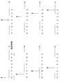
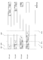
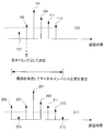
- FIG. 27 is a diagram illustrating an example of estimating the channel impulse response based on the autocorrelation and determining the synchronization position based on the estimated channel impulse response.
- the upper part represents autocorrelation.
- the threshold 103 is determined by the peak path 101. Since the path with the minimum delay time exceeding the threshold 103 is the path 105, the path 105 is determined as a temporary timing here.
- the lower part of FIG. 27 represents the channel impulse response estimated in the search range determined from the position of the path 105.
- Paths 201 to 215 are paths constituting a channel impulse response, and have a peak path 201. Thereby, the threshold value 217 is determined. Since the path with the minimum delay time exceeding the threshold 217 is the path 203, the synchronization position is determined with the path 203 as the preceding path.
- Non-Patent Document 1 when the search range becomes very large, such as a system with many subcarriers, the error from the true value of the estimated value increases due to noise enhancement, and the accuracy of the synchronization position deteriorates.
- the present invention has been made in view of such circumstances, and an object of the present invention is to provide a receiving apparatus, a receiving method, a control program, and an integrated circuit capable of determining a synchronization position with high accuracy.
- the receiving apparatus of the present invention is a receiving apparatus that determines a preceding path position from a received multipath, estimates a channel impulse response using a frequency response estimated value, and determines the fitness between the estimated value and the path.
- a propagation path adaptability calculation unit that calculates the propagation path adaptability shown for each path, an unnecessary candidate path removal unit that removes candidate paths that cannot improve the propagation path adaptability, and a candidate path that improves the propagation path adaptability
- a path extraction unit that extracts at least one of the extracted paths, and a synchronization correction determination unit that determines a temporal position of a candidate path with the shortest delay time among the extracted paths as a preceding path position. It is said.
- the receiving apparatus removes candidate paths that cannot improve the propagation path suitability, extracts at least one candidate path that improves the propagation path suitability as an extraction path, and among the extracted paths, the delay time is the longest. Since the temporal position of the small candidate path is determined as the preceding path position, the path can be selected and estimated, the noise and interference reduction effect is increased, and noise enhancement can be suppressed.
- the receiving apparatus of the present invention further includes a search range determination unit that determines a temporary preceding path position from the received multipath, and determines a search range of the preceding path based on the determined temporary preceding path position. It is characterized by that.
- the receiving apparatus determines the temporary preceding path position from the received multipath, and determines the search range of the preceding path based on the determined temporary preceding path position, and thus exceeds the guard interval (Guard Interval; GI). Even when there is a delay path, synchronization can be performed with high accuracy.
- Guard Interval Guard Interval
- the search range determining unit is characterized in that a position having a delay time smaller than the temporary preceding path position is set as a head of the search range.
- the receiving apparatus sets the position where the delay time is smaller than the temporary preceding path position as the head of the search range, so that even when there is a delay path exceeding the guard interval (Guard Interval; GI), synchronization can be performed with high accuracy.
- Guard Interval Guard Interval
- the search range determination unit is characterized in that a position having a delay time larger than the temporary preceding path position is set as the end of the search range.
- the receiving apparatus sets the position where the delay time is larger than the temporary preceding path position as the end of the search range, so that even if there is a delay path exceeding the guard interval (Guard Interval; GI), synchronization can be performed with high accuracy.
- Guard Interval Guard Interval
- the search range determination unit is characterized in that a position having a delay time larger than the provisional preceding path position by a maximum delay time is set as the end of the search range.
- the receiving apparatus sets the position where the delay time is larger than the temporary preceding path position by the maximum delay time as the end of the search range, so even if there is a delay path exceeding the guard interval (Guard Interval; GI), Synchronize with accuracy.
- Guard Interval Guard Interval
- the receiving apparatus of the present invention is characterized in that an information amount criterion is used as the propagation path adaptability.
- the receiving apparatus uses the information criterion as the propagation path adaptability, it is possible to select and estimate a path, increase noise and interference reduction effects, and suppress noise enhancement.
- the information amount criterion is a Bayes information amount criterion.
- the receiving apparatus can select and estimate the path, increase the noise and interference reduction effect, and suppress noise enhancement.
- a time-frequency conversion unit that converts a received signal from a time-domain signal to a frequency-domain signal, and propagation in the frequency domain using the frequency-domain received signal and the reference signal
- a frequency response estimation unit that estimates a frequency response that is a path and outputs a frequency response estimation value
- the propagation path fitness calculation unit calculates the propagation path fitness using the frequency response estimation value It is characterized by that.
- the receiving apparatus calculates the channel adaptability using the frequency response estimation value, it can be estimated by selecting a path, noise and interference can be reduced, and noise enhancement can be suppressed.
- the propagation path fitness calculation unit estimates the channel impulse response using a received signal corresponding to a time at which a reference signal is mapped.
- the transmitting apparatus since the receiving apparatus estimates the channel impulse response using the received signal corresponding to the time at which the reference signal is mapped, the transmitting apparatus performs single carrier transmission that transmits a continuous signal in the time domain. Then, pilot symbols that are temporally continuous can be inserted, and synchronization correction can be performed using the pilot symbols as reference signals.
- the receiving apparatus when the receiving apparatus detects that there is no candidate path having a delay time smaller than that of the path having the minimum delay time among the extracted paths, the receiving apparatus determines the preceding path position. It can be estimated, noise and interference reduction effect is increased, and noise enhancement can be suppressed.
- the synchronization correction determination unit determines the preceding path position when there are no candidate paths as a result of removing candidate paths that cannot improve the channel suitability. It is characterized by.
- the receiving apparatus determines the preceding path position when there are no candidate paths as a result of removing the candidate paths that cannot improve the propagation path adaptability, so that the path can be selected and estimated, and noise and interference can be estimated.
- the reduction effect increases and noise enhancement can be suppressed.
- the channel frequency response estimated value configured from the extraction path is converted from a time domain signal to a frequency domain signal, and a frequency response time frequency for outputting the frequency response estimated value is output. It is characterized by including a conversion unit.
- the receiving apparatus converts the channel impulse response estimated value formed of the extraction path from the time domain signal to the frequency domain signal and outputs the frequency response estimated value, so that the circuit scale can be reduced.
- a plurality of synchronization units including the propagation path fitness calculation unit, the unnecessary candidate path removal unit, the path extraction unit, and the synchronization correction determination unit, and the synchronization units
- a propagation path conformity determination unit that determines a path position corresponding to the largest propagation path conformance among the obtained propagation path conformances as a preceding path position.
- the receiving apparatus determines the path position corresponding to the largest propagation path adaptability among the propagation path adaptability obtained from each synchronization unit as the preceding path position, the synchronization that maximizes the propagation path adaptability is determined.
- Position and channel impulse response estimates can be employed.
- a receiving method of the present invention is a receiving method for determining a preceding path position from a received multipath, estimating a channel impulse response using a frequency response estimated value, and calculating the estimated value and the path Extracting at least one candidate path that improves the channel adaptability, calculating a channel adaptability indicating the adaptability for each path, removing a candidate path that cannot improve the channel adaptability It includes at least a step of making an extraction path and a step of determining a temporal position of a candidate path having the shortest delay time among the extraction paths as a preceding path position.
- the receiving apparatus removes candidate paths that cannot improve the propagation path suitability, extracts at least one candidate path that improves the propagation path suitability as an extraction path, and among the extracted paths, the delay time is the longest. Since the temporal position of the small candidate path is determined as the preceding path position, the path can be selected and estimated, the noise and interference reduction effect is increased, and noise enhancement can be suppressed.
- a control program of the present invention is a control program for a receiving apparatus that determines a preceding path position from a received multipath, and estimates a channel impulse response using a frequency response estimated value, At least one process for calculating a channel adaptability indicating the adaptability to a path for each path, a process for removing candidate paths that cannot improve the channel adaptability, and a candidate path that improves the channel adaptability
- the receiving apparatus removes candidate paths that cannot improve the propagation path suitability, extracts at least one candidate path that improves the propagation path suitability as an extraction path, and among the extracted paths, the delay time is the longest. Since the temporal position of the small candidate path is determined as the preceding path position, the path can be selected and estimated, the noise and interference reduction effect is increased, and noise enhancement can be suppressed.
- the integrated circuit of the present invention is an integrated circuit that is mounted on a receiving device to cause the receiving device to perform a plurality of functions, and has a function of receiving a multipath and a frequency response estimation value.
- a channel impulse response is estimated using, a function of calculating a channel adaptation indicating the fitness between the estimated value and the path for each path, a function of removing candidate paths that cannot improve the channel adaptation, and A function of extracting at least one candidate path for improving propagation path adaptability to be an extraction path; a function of determining a temporal position of a candidate path having the smallest delay time among the extracted paths as a preceding path position; It is characterized in that a series of functions described above is caused to be exhibited by the receiving apparatus.
- the receiving apparatus removes candidate paths that cannot improve the propagation path suitability, extracts at least one candidate path that improves the propagation path suitability as an extraction path, and among the extracted paths, the delay time is the longest. Since the temporal position of the small candidate path is determined as the preceding path position, the path can be selected and estimated, the noise and interference reduction effect is increased, and noise enhancement can be suppressed.
- the synchronization accuracy can be greatly improved.
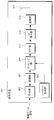
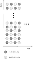
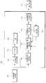
- 1 is a schematic block diagram of a transmission device according to a first embodiment of the present invention. It is a figure which shows the example in which the mapping part 309 maps a pilot symbol and a modulation signal. It is a schematic block diagram which shows the structure of the receiver 401 which concerns on the 1st Embodiment of this invention. It is a schematic block diagram which shows the structure of the synchronizer 409 which concerns on the 1st Embodiment of this invention. It is a figure which shows correlation (rho) t used for specifying the position of a preceding path
- the signal R i, n of the i-th symbol n-th subcarrier is Ne points before the true position.
- FIG. 6 is a diagram illustrating a path structure when a path position is present between a sampling position of a received signal and a sampling point in the first embodiment of the present invention. It is a schematic block diagram which shows the structure of the receiver 901 which concerns on the 2nd Embodiment of this invention. It is a schematic block diagram which shows the structure of the synchronizer 903 which concerns on the 2nd Embodiment of this invention.
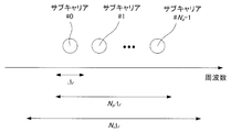
- FIG. 28 is a diagram illustrating a transmission signal including N subcarriers.
- Delta f is the 15kHz if LTE (3.9 generation mobile communication system) with the values determined by the system. This signal is transmitted from the transmission side and sent to the reception side through the propagation path.
- N is the N a may be an integer greater than, but the nature of FFT, to a power of two is common (power of two fastest computable). Since the signal received by the receiver is naturally an analog signal (continuous), filtering and AD conversion are performed so that digital signal processing can be performed.
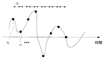
- FIG. 29 is a diagram illustrating a state in which an analog reception signal is sampled at a time interval ⁇ t .
- ⁇ t corresponds to 1 / (N ⁇ f ).
- the delay time of the delay path is modeled as one that can be handled by an integer multiple of ⁇ t . Therefore, for example, when N is set to 2048 in LTE, the path interval is 0.0326 ⁇ s.
- FIG. 1 is a schematic block diagram of a transmission apparatus according to the first embodiment of the present invention.
- the transmission apparatus according to this embodiment is referred to as a transmission apparatus 301.
- a transmission apparatus 301 includes a pilot generation unit 303, an encoding unit 305, a modulation unit 307, a mapping unit 309, an IFFT unit (also referred to as a frequency time conversion unit) 311, a GI insertion unit 313, a transmission unit 315, and a transmission antenna. 317 and transmit an OFDM signal.
- Pilot generating section 303 generates a pilot symbol in which the receiving apparatus stores in advance the amplitude value of the waveform (or signal sequence thereof), and outputs the pilot symbol to mapping section 309.
- the receiving device is referred to as a receiving device 401.
- Reception apparatus 401 performs propagation path estimation and synchronization using pilot symbols as reference signals.
- the encoding unit 305 encodes information bits to be transmitted to the reception apparatus 401 using an error correction code such as a convolutional code, a turbo code, and an LDPC (Low Density Parity Check) code, Is generated.
- the encoding unit 305 outputs the generated encoded bits to the modulation unit 307.
- the modulation unit 307 modulates the coded bits input from the coding unit 305 using a modulation scheme such as PSK (Phase Shift Keying) or QAM (Quadrature Amplitude Modulation). Generate a symbol.
- Modulation section 307 outputs the generated modulation symbol to mapping section 309.
- the mapping unit 309 maps the pilot symbols input from the pilot generation unit 303 and the modulation symbols input from the modulation unit 307 to resources (time-frequency bands) based on predetermined mapping information. And the generated frequency domain signal is output to the IFFT unit 311.
- a resource is a unit in which a modulation symbol is arranged, which is composed of one subcarrier and one later-described FFT interval in a frame transmitted by the transmission apparatus 301.
- the mapping information is determined by the transmission apparatus 301 and notified from the transmission apparatus 301 to the reception apparatus 401 in advance.
- FIG. 2 is a diagram illustrating an example in which the mapping unit 309 maps pilot symbols and modulated signals.
- the IFFT unit 311 performs frequency-time conversion on the frequency domain signal input from the mapping unit 309 to generate a time domain signal.
- a unit time interval for performing IFFT is referred to as an FFT interval.
- the IFFT unit 311 outputs the generated time domain signal to the GI insertion unit 313.
- the GI insertion unit 313 adds a guard interval (Guard Interval: GI) for each signal in the FFT interval to the time domain signal input from the IFFT unit 311.
- GI Guard Interval
- the guard interval is a known signal or the like using a cyclic prefix (Cyclic Prefix: CP) that is a part of the rear of the signal in the FFT interval, zero padding in which the zero interval continues, Golay code, or the like.
- CP Cyclic Prefix
- the GI insertion unit 313 adds such a signal to the front of the signal in the FFT interval.
- the FFT interval and the time interval (referred to as GI interval) of the guard interval added to the signal in the time interval by the GI insertion unit 313 are collectively referred to as an OFDM symbol interval.
- a signal in the OFDM symbol section is called an OFDM symbol.
- the GI insertion unit 313 outputs a signal with the guard interval added thereto to the transmission unit 315.
- a guard interval may be inserted behind the FFT interval. For example, when a cyclic prefix is used, a part of the replica in front of the FFT interval is added behind the signal in the FFT interval. In the case of a cyclic prefix, the periodicity may be maintained in the OFDM symbol period, and is not limited to the above.
- the transmission unit 315 performs digital / analog conversion on the signal input from the GI insertion unit 313 and shapes the waveform of the converted analog signal.
- the transmission unit 315 up-converts the waveform-shaped signal from the baseband to the radio frequency band, and transmits the signal from the transmission antenna 317 to the reception device 401.
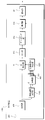
- FIG. 3 is a schematic block diagram showing the configuration of the receiving device 401 according to the first embodiment of the present invention.
- a receiving apparatus 401 includes a receiving antenna 403, a receiving unit 405, a search range determining unit 407, a synchronizing unit 409, a GI removing unit 411, an FFT unit (also referred to as a time frequency converting unit) 413, a demapping unit 415, a propagation A path estimation unit 417, a demodulation unit 419, and a decoding unit 421 are included.
- the reception unit 405 receives the transmission signal transmitted from the transmission device 301 via the reception antenna 403.
- the receiving unit 405 performs frequency conversion and analog-digital conversion on the received signal.
- the search range determination unit 407 determines a path search range from the received signal input from the reception unit 405. This specific processing will be described later together with the operation principle.
- Synchronizing section 409 uses the received signal of the subcarrier to which the pilot symbol is transmitted and the pilot symbol in the search range determined by search range determining section 407 to detect the path that improves the channel suitability and performs synchronization. Do. Details of the synchronization unit 409 will be described later with reference to the drawings. The result is output to the GI removal unit 411.
- the GI removal unit 411 uses the reception signal input from the reception unit 405 and the synchronization information input from the synchronization unit 409, removes the guard interval from the reception signal, and outputs the guard interval to the FFT unit 413.
- the FFT unit 413 performs time-frequency conversion on the time domain signal input from the GI removal unit 411 and outputs the converted frequency domain signal to the demapping unit 415.
- Demapping section 415 performs demapping based on the mapping information notified in advance from transmitting apparatus 301, and outputs the received signal of the subcarrier to which the separated pilot symbol is transmitted to propagation path estimating section 417. In addition, the reception signal of the subcarrier to which data is transmitted is output to demodulation section 419.
- the propagation path estimation unit 417 calculates a demodulation frequency response estimation value using the received signal of the subcarrier to which the pilot symbol is transmitted and the pilot symbol, and outputs the estimated frequency response estimation value to the demodulation unit 419.
- a known technique such as a least square method, MMSE (Minimum Mean Square Error), or DFT (Discrete Fourier Transform) method may be used.
- the propagation path estimation part 417 uses the pilot symbol memorize
- Demodulation section 419 uses the demodulation frequency response estimation value and noise power input from propagation path estimation section 417 to calculate filter coefficients such as a ZF (Zero Forcing) criterion and an MMSE criterion.
- Demodulation section 419 compensates for signal amplitude and phase fluctuations (referred to as propagation path compensation) using the calculated filter coefficients.
- the demodulation unit 419 outputs a bit log likelihood ratio (LLR; Log Likelihood Ratio) as a result of the demodulation process to the decoding unit 421.
- LLR bit log likelihood ratio
- the decoding unit 421 performs, for example, maximum likelihood decoding (MLD; Maximum; Likelihood Decoding), maximum a posteriori probability (MAP), log-MAP, Max ⁇ on the demodulated symbols input from the demodulation unit 419.
- MLD maximum likelihood decoding
- MAP maximum a posteriori probability
- log-MAP log-MAP
- Max ⁇ maximum a posteriori probability
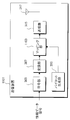
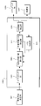
- FIG. 4 is a schematic block diagram showing the configuration of the synchronization unit 409 according to the first embodiment of the present invention.
- the synchronization unit 409 includes a GI removal unit 501, an FFT unit 503, a demapping unit 505, a frequency response estimation unit 507, a channel match calculation unit 509, an unnecessary candidate path removal unit 511, a synchronization correction determination unit 513, and a path extraction unit 515. Consists of This specific processing will be described later together with the operation principle.
- the received signal r i, k of the i-th symbol at the k-th discrete time received by the receiving unit 405 is expressed by the following equations (1) and (2).
- D is the maximum delay time
- h i, d is the complex amplitude in the path of the channel number d of the i-th symbol (referred to as the d-th path)
- s i, k are the time domain of the i-th symbol k-th discrete time. This is a transmission signal
- z i, k is noise in the time domain of the i-th symbol.
- N is the number of points in the FFT interval
- S i, n is the modulation signal of the i-th symbol of the n-th subcarrier
- N g is the number of points in the GI interval (see FIG. 6 described later)
- j is an imaginary unit.
- the received signal at this point is denoted by ru .
- the search range determining section 407 using the correlation between the time waveform of the guard interval correlation and the reference signal using the r u, to locate the previous pass.
- the correlation [rho tau expressed by the following equation (3).
- the width of the sum may be set within a range where a sufficient correlation can be obtained.
- it may be the sum of one OFDM symbol, may be fixed when the receiving apparatus 401 is designed, or may be updated when firmware, software, or the like of the receiving apparatus 401 is updated.
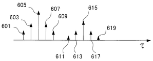
- Figure 5 is a search range determining unit 407 according to the first embodiment of the present invention, is a diagram showing the correlation [rho tau used to identify the position of the previous pass.
- Paths 601 to 619 are strongly correlated parts and are path candidates. Actually, there is also noise, so there are minute values at other positions.
- the path 601 is considered as the preceding path, and this position or a position offset further before is considered as the preceding path position in consideration of the possibility that there is a path that could not be observed at the previous time.
- This offset amount may be fixed when the receiving apparatus 401 is designed, or may be updated when firmware, software, or the like of the receiving apparatus 401 is updated. The offset amount may be zero.
- a threshold value is calculated from a peak value, and a path with a minimum delay time exceeding the threshold value may be set as a preceding path position, or a position offset before the position obtained in this way is used. It may be the preceding path position.
- the preceding path position determined in this way is called a temporary preceding path position.
- the search range determination unit 407 also determines a search range for performing synchronization thereafter. Specifically, from the position of the preceding path determined here to a position where the delay time is small by T, a position where the delay time is large by L, that is, the delay time -TL is set as the search range.
- Specific values of T and L may be determined at the stage of designing the receiving device, or may be made variable at the design stage and updated when updating the firmware, software, etc. of the receiving device. Also good. That is, T may be 0.
- L is desirably large enough to cover the maximum delay time, but may be a value similar to T.
- the GI removal unit 501 removes the GI from the received signal based on the preceding path position determined by the search range determination unit 407, and extracts the FFT interval of the received signal. Thereafter, the FFT unit 503 performs time-frequency conversion in the FFT interval of the received signal to convert it to a received signal in the frequency domain. At this time, if the preceding path position determined by the search range determination unit 407 is Ne points before the true position, the signal R i, n of the i-th symbol n-th subcarrier is expressed by the following equation (5). .
- Z i, n, ⁇ Ne is frequency domain noise.
- H i, n, ⁇ Ne is the frequency response of the i-th symbol and the n-th subcarrier , and is expressed by the following equations (6) and (7).
- FIG. 6 shows the signal of the i-th symbol n-th subcarrier when the preceding path position determined by the search range determination unit 407 according to the first embodiment of the present invention is Ne points before the true position.
- the signal R i, n of the i-th symbol n-th subcarrier is expressed by the following equations (8) and (9).
- FIG. 7 shows this state.
- N e As a result of shifting back by N e , ISI and ICI occur because the preceding path portion 801 is a different OFDM symbol. For this reason, transmission characteristics deteriorate.
- the frequency response of the i-th symbol n-th subcarrier will be described as Hi, n .
- n 1 , n 2 ,..., n P are pilot subcarriers, and frequency response estimation vectors H i, P are defined as in the following equation (10).
- n 1 is the lowest subcarrier
- n 2 is the next subcarrier
- n 3 is the next subcarrier
- N P is the number of pilot subcarriers
- I x is the identity matrix of size x.
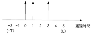
- the delay time -T to L represents the search range, and is determined by the search range determination unit 407 determining the preceding path position. A negative delay time is also taken into consideration from the position of the preceding path, and -T is considered. L is an assumed maximum delay time.
- C i, h is a diagonal matrix of size L + T + 1 having the value of the average power of paths from ⁇ T to L as main diagonal elements. Since the average power is unknown, a constant value ⁇ is used. However, only a path that improves the channel matching degree is set to ⁇ , and other paths are set to 0.
- the channel adaptability is a quantity that quantitatively represents the adaptability between the calculated estimated value and the observed data (received signal here).
- FIG. 8 is a diagram showing the average power of each path according to the first embodiment of the present invention.
- C i, h is expressed by the following equation (15).
- the preceding path position is set.
- the search range determination unit 407 shifts by the detected amount from that determined. The shift is also performed when the path with the shortest delay time that improves the channel adaptability is in the positive delay time.
- the propagation path adaptability calculation unit 509 uses the frequency response estimation value input from the frequency response estimation unit 507, and in addition to the paths extracted so far, increases one path among candidate paths to generate a channel impulse response. presume. This is performed for all candidate paths, and the propagation path suitability is calculated for each. However, since there is no extracted path in the first process, one-path estimation with all candidate paths is performed to calculate the propagation path adaptability.
- FIG. 9 is a diagram for explaining one-path estimation using all candidate paths according to the first embodiment of the present invention.
- the unnecessary candidate path removal unit 511 deletes, from the candidate paths, a path that has fallen below the propagation path fitness before increasing the number of paths from the input from the propagation path fitness calculation section 509.
- this deletion processing is not performed.
- the synchronization correction determination unit 513 detects that there is no candidate path having a delay time shorter than the extracted path having the shortest delay time, the synchronization correction determination unit 513 ends the process of the synchronization unit 409.
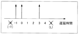
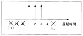
- FIGS. 10A to 10C are diagrams illustrating average power of each path after the processing of the synchronization unit 409 according to the first embodiment of the present invention is completed.
- FIG. 10 shows a case where three passes are selected after the processing of the synchronization unit 409 is completed.
- the position where the path stands represents the path extracted by the processing so far, and the position marked with x represents the deleted candidate path.
- FIG. 10A shows an example in which the same path as the synchronization position determined by the search range determination unit 407 is the preceding path. In this case, the synchronization position does not change.
- FIG. 10B shows an example in which a path is detected at a negative delay time. It is considered that the problem shown in FIG.
- FIG. 10C is an example when it is detected that the synchronization has shifted in the positive direction. As described above, since the problem as shown in FIG. 6 may occur, the shift is also performed in this case.
- the shift amount (here, 1) is output to the GI removal unit 411.
- the synchronization correction determination unit 513 does not particularly operate and moves to the path extraction unit 515.
- the path extraction unit 515 extracts a path that maximizes the propagation path suitability from candidate paths that have not been removed by the unnecessary candidate path removal unit 511.
- the extracted path position is removed from the candidate paths, and the extracted path information is output to the propagation path fitness calculation unit 509.
- the synchronization unit 409 repeats these processes until the synchronization correction determination unit 513 determines the shift amount.
- Akaike Information Criterion (AIC), Bayesian Information Criterion (BIC), Minimum Description Length (MDL) may be used for propagation path conformity, For example, model evidence derived from the pilot structure of FIG. 2 may be used.
- the propagation path adaptability when using a BIC is expressed by the following equation (16). However, N s is the number of paths extracted up to that point.
- the GI removal unit 411 removes the GI from the reception signal input from the reception unit 405 based on the synchronization position determined by the synchronization unit 409.
- the FFT unit 413 performs time-frequency conversion to convert the received signal in the frequency domain.
- the channel response estimation unit 417 estimates the frequency response and uses it as a demodulation frequency response.
- the demodulation unit 419 calculates a demodulation symbol S ′ i, n as shown in the following equation (17), for example, when filtering based on MMSE is used.
- ⁇ z 2 is the power of Z i, n and is expressed as in the following equation (18).
- E [X] represents an ensemble average of X. This power can be calculated as in the following equation (19), and the result is used in equation (17) to calculate the demodulated symbol S ′ i, n .
- ⁇ z ′ 2 is an estimated value of ⁇ z 2
- P i is a set representing pilot subcarriers in the i-th symbol. Note that this is a calculation method that utilizes the fact that equation (19) can be expressed by the following equation (20), assuming that a sufficient number of arithmetic averages are equal to the ensemble average.
- This equation is for the case where the pilot symbol power is normalized to 1 and the frequency response power average is normalized to 1. That is, this equation is a case where the following equation (21) is satisfied.
- the demodulator 419 calculates a bit log likelihood ratio from the demodulated symbol S ′ i, n in Expression (17).
- An equivalent amplitude gain is used for this calculation process.
- the bit log likelihood ratio ⁇ is expressed by the following equations (23) and (24) with respect to the equivalent amplitude gain ⁇ i, n of the n-th subcarrier expressed by the following equation (22).
- Equation (23) and (24) are respectively expressed as the bit log likelihood ratios ⁇ (b i, n ) of the first bit b i, n, 0 and the second bit b i, n, 1. , 0 ), ⁇ (b i, n, 1 ).
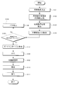
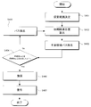
- FIG. 11 is a flowchart showing the operation of the receiving apparatus according to the first embodiment of the present invention.
- the operation shown in this figure is processing after the reception unit 405 in FIG. 3 outputs the received signal to the search range determination unit 407.
- the search range determination unit 407 determines a previous path position and a search range for synchronization from the received signal (step S101). Then, it progresses to step S102.
- the frequency response estimation unit 507 estimates the frequency response of the pilot subcarrier using the received signal that has been time-frequency converted based on the preceding path position determined in step S101, and sets the frequency response estimated value (step S102). Thereafter, the process proceeds to step S103.
- the channel adaptation calculation unit 509 uses the frequency response estimation value obtained in step S102, and in addition to the paths determined so far by the path extraction unit 515, the channel impulse response when one of the candidate paths is added. Is estimated (step S103). This process is performed as many times as the number of candidate paths, and the channel adaptability is calculated for each. Thereafter, the process proceeds to step S104.
- Unnecessary candidate path removal unit 511 removes, from the candidate paths, paths corresponding to the degree of propagation path adaptation obtained in step S103 that is lower than the degree of propagation path adaptation before adding one path (step S104). Thereafter, the process proceeds to step S105, and synchronization correction determination is performed.
- the synchronization correction determination unit 513 determines the shift amount to be applied to the synchronization position when there is no candidate path having a delay time shorter than the path having the smallest delay time among the extracted paths (step S105: Yes). Determine and proceed to step S107. When that is not right (step S105: No), it progresses to step S106.
- the path extraction unit 515 determines, as an extraction path, a path corresponding to the largest of the propagation path adaptability of candidate paths remaining as a result of step S104 (step S106). Thereafter, the process returns to step S103.
- the GI removal unit 411 removes the guard interval from the received signal based on the synchronization position determined in step S105 (step S107). Thereafter, the process proceeds to step S108.
- the FFT unit 413 performs time-frequency conversion on the signal obtained in step S107 (step S108).
- the demapping unit 415 separates data and pilot symbols from the obtained frequency domain signal.
- the reception signal of the pilot subcarrier is output to propagation path estimation section 417. Thereafter, the process proceeds to step S109.
- Propagation path estimation section 417 performs propagation path estimation using the pilot subcarrier received signal obtained in step S108, and outputs a demodulation frequency response estimation value to demodulation section 419 (step S109). Then, it progresses to step S110.
- Demodulation section 419 performs demodulation using the reception signal of the data subcarrier obtained in step S108 and the frequency response estimation value for demodulation obtained in step S109 (step S110). Thereafter, the process proceeds to step S111.
- the decoding unit 421 performs decoding using the demodulation result obtained in step S110 (step S111). Thereafter, the receiving device 401 ends the operation.
- the synchronization unit 409 estimates the frequency response of the pilot subcarrier, deletes the path that cannot improve the channel suitability from the candidate paths, and improves the channel match.
- the process of extracting the path is repeated, and the process is terminated when there is no candidate path having a delay time that is further shorter than that of the extracted path having the shortest delay time. At this time, if the extracted path with the smallest delay time is not the path with the delay time 0, synchronization correction is performed. In this way, since the path is selected and estimated, the noise and interference reduction effect is increased, and noise enhancement can be suppressed.
- the frequency response is estimated using the pilot symbol for each OFDM symbol and the shift amount with respect to the synchronization position determined by the search range determination unit 407 is described.
- the position of the pilot subcarrier is the lowest subcarrier, the second subcarrier, the second subcarrier, and so on.
- Locations that are not subcarriers may also be estimated using pilot symbols of OFDM symbols having different times.
- noise and interference can be reduced by using pilot symbols at different times. In this way, the synchronization correction accuracy can be further improved.
- an arithmetic average may be performed, or a weighted average may be performed according to the propagation path fluctuation.
- pilot symbols are used as reference signals used for frequency response estimation
- estimation may be performed using determined data. Specifically, it can be realized by feeding back the output of the demodulator 419 or the decoder 421 to the frequency response estimator 507.
- a case has been described in which channel impulse responses are estimated by adding candidate paths, and a path that improves the channel suitability is extracted most. Good. For example, three paths may be selected in descending order of improvement, or a condition may be added that these three paths do not select ones with a short delay time. For example, in the case of processing delay times -2 to 5 as shown in FIG. 8, if the path extraction unit 515 selects a path with a delay time of 0, two neighboring paths (-2, -1, 1, 1, 2) are It can be realized by not selecting at the same time.
- the method of detecting a path up to the delay time L and performing synchronization correction has been described.
- the number of candidate paths may be limited in advance by another method.
- the frequency response estimation value obtained by the frequency response estimation unit 507 is subjected to frequency time conversion, and only the position where the power is high is left as a candidate path among the obtained temporary estimation values of the channel impulse response. Processing after the calculation unit 509 is performed.
- the path position exists at the sampling position of the received signal as in Expression (1). However, the interval between the sampling points may be considered. In that case, the Fourier transform matrix of Equation (13) includes the decimal point position.
- FIG. 12 is a diagram showing a path structure when the path position exists between the sampling position of the received signal and the sampling point in the first embodiment of the present invention.
- the Fourier transform matrix is as shown in the following equation (25).
- the communication system has been described for multi-carrier signal communication.
- the present invention is not limited to this and is also applicable to single-carrier signal communication using FFT. can do.
- the transmission device 301 transmits a multicarrier signal or the like that maps pilot symbols in the frequency domain, and the reception device 401 calculates a frequency response estimation value in the pilot subcarrier, and estimates a channel impulse response.
- the paths that improve the channel adaptability are selected one by one, and the synchronization correction amount is determined when the necessity of synchronization correction is determined.
- the transmission apparatus according to the present embodiment has the same configuration as the transmission apparatus 301 according to the first embodiment, and thus description thereof is omitted.
- FIG. 13 is a schematic block diagram showing the configuration of the receiving device 901 according to the second embodiment of the present invention. Comparing the receiving apparatus 901 according to the present embodiment (FIG. 13) and the receiving apparatus 401 according to the first embodiment (FIG. 3), it does not have the propagation path estimation unit 417, and the operation of the synchronization unit 903 is the synchronization unit 409. And different. However, the functions of other components (receiving antenna 403, receiving unit 405, search range determining unit 407, GI removing unit 411, FFT unit 413, demapping unit 415, demodulation unit 419, decoding unit 421) are the first This is the same as the embodiment. A description of the same functions as those in the first embodiment is omitted. Note that, unlike the first embodiment, the value set to L is preferably a value that can cover the maximum delay time.
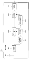
- FIG. 14 is a schematic block diagram showing the configuration of the synchronization unit 903 according to the second embodiment of the present invention.
- the operation of the synchronization correction determination unit 1001 is different, and the FFT unit 1003 (propagation time) Also called a frequency converter).
- the functions of other components GI removal unit 501, FFT unit 503, demapping unit 505, frequency response estimation unit 507, channel match calculation unit 509, unnecessary candidate path removal unit 511, path extraction unit 515) Is the same as in the first embodiment.
- a description of the same functions as those in the first embodiment is omitted.
- the shift amount is determined and the operation of the synchronization unit 409 is terminated. I was letting.
- the shift amount is determined, and the estimated value of the channel impulse response of Equation (11) estimated simultaneously is calculated by the FFT unit 1003. Output to.
- the FFT unit 1003 performs time-frequency conversion on the channel impulse response estimation value input from the synchronization correction determination unit 1001 to convert it to a frequency response estimation value. At this time, the time frequency conversion is performed after the shift amount determined by the synchronization correction determination unit 1001 is reflected in the channel impulse response. The result is output to demodulation section 419.
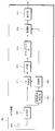
- FIG. 15 is a flowchart showing the operation of the receiving apparatus according to the second embodiment of the present invention.
- the operation shown in this figure is a process after the reception unit 405 in FIG. 13 outputs a reception signal to the search range determination unit 407.
- the search range determination unit 407 determines a previous path position and a search range for synchronization from the received signal (step S201). Thereafter, the process proceeds to step S202.
- the frequency response estimation unit 507 estimates the frequency response of the pilot subcarrier using the received signal subjected to time-frequency conversion based on the preceding path position determined in step S201, and sets the frequency response estimated value (step S202). Then, it progresses to step S203.
- the channel adaptation calculation unit 509 uses the frequency response estimation value obtained in step S202, and in addition to the path determined by the path extraction unit 515, the channel impulse response when one of the candidate paths is added. Is estimated. This process is performed as many times as the number of candidate paths, and the channel adaptability is calculated (step S203). Thereafter, the process proceeds to step S204.
- the unnecessary candidate path removal unit 511 removes, from the candidate paths, paths corresponding to the degree of propagation path adaptation obtained in step S203 that is lower than the degree of propagation path adaptation before adding one path (step S204). Thereafter, the process proceeds to step S205, and synchronization correction determination is performed.
- the synchronization correction determination unit 1001 determines the shift amount to be applied to the synchronization position and uses the estimated channel impulse response estimated value as the frequency. After converting to the response estimated value, the response is output to the demodulator 419, and the process proceeds to step S207. When that is not right (step S205: No), it progresses to step S206.
- the path extraction unit 515 determines, as an extraction path, a path corresponding to the largest of the propagation path adaptability of candidate paths remaining as a result of step S204 (step S206). Then, it returns to step S203.
- GI removal unit 411 removes the guard interval from the received signal based on the synchronization position determined in step S205 (step S207). Thereafter, the process proceeds to step S208.
- the FFT unit 413 performs time-frequency conversion on the signal obtained in step S207 (step S208).
- the demapping unit 415 separates data and pilot symbols from the obtained frequency domain signal. Thereafter, the process proceeds to step S209.
- Demodulation section 419 performs demodulation using the data subcarrier received signal obtained in step S208 and the demodulation frequency response estimation value obtained in step S205 (step S209). Thereafter, the process proceeds to step S210.
- the decoding unit 421 performs decoding using the demodulation result obtained in step S209 (step S210). Thereafter, the receiving device 901 ends the operation.
- the propagation path estimation is performed at the same time in the process of the synchronization section 903, the propagation path estimation section is not required, so that the circuit scale can be reduced.
- the transmission apparatus 301 transmits a multicarrier signal or the like that maps pilot symbols in the frequency domain, and the reception apparatus 401 or the reception apparatus 901 calculates a frequency response estimation value in the pilot subcarrier.
- the synchronization correction amount is determined by selecting one path at a time for improving the channel adaptability using channel impulse response estimation by MMSE.
- transmitting apparatus 1101 performs single carrier transmission for transmitting a continuous signal in the time domain, inserts a pilot symbol that is continuous in time, and performs synchronization correction using the pilot symbol as a reference signal. The case will be described.
- FIG. 16 is a schematic block diagram illustrating a configuration of a transmission device 1101 according to the third embodiment of the present invention.
- the mapping unit 1103 does not have the IFFT unit 311 and the GI insertion unit 313. Is different.
- the functions of other components are the same as those in the first or second embodiment. The description of the same function as in the first or second embodiment is omitted.
- Mapping section 1103 generates a time-domain signal by mapping pilot symbols input from pilot generation section 303 and modulation symbols input from modulation section 307 to the time domain based on predetermined mapping information.
- the generated time domain signal is output to the transmission unit 315.
- the mapping information is determined by the transmission apparatus 1101 and notified in advance from the transmission apparatus 1101 to the reception apparatus 1201 (the reception apparatus according to the third embodiment of the present invention is the reception apparatus 1201).
- FIG. 17 is a diagram illustrating an example in which the mapping unit 1103 according to the third embodiment of the present invention maps information data symbols and pilot symbols.
- white squares represent information data symbols
- shaded squares represent pilot symbols.
- the pilot symbols are transmitted in K symbol sequences.
- FIG. 18 is a schematic block diagram showing the configuration of the receiving device 1201 according to the third embodiment of the present invention.
- the receiving apparatus 1201 (FIG. 18) according to the present embodiment is compared with the receiving apparatus 401 (FIG. 3) according to the first embodiment, the GI removing unit 411 and the FFT unit 413 are not included, and the synchronizing unit 1203, the propagation path
- the estimation unit 1205, the demodulation unit 1207, and the demapping unit 1209 are different.
- the functions of other components (receiving antenna 403, receiving unit 405, search range determining unit 407, decoding unit 421) are the same as those in the first embodiment. A description of the same functions as those in the first embodiment is omitted.
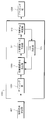
- FIG. 19 is a schematic block diagram showing the configuration of the synchronization unit 1203 according to the third embodiment of the present invention.
- the GI removal unit 501, the FFT unit 503, and the frequency response estimation unit 507 are not included, and the processing of the demapping unit 1301 and the propagation path fitness calculation unit 1303 is performed. Is different.
- the functions of other components are the same as those in the first embodiment. A description of the same functions as those in the first embodiment is omitted.
- the propagation path fitness calculation unit 1303 uses a reception signal corresponding to the time at which the pilot symbol input from the demapping unit 1301 is transmitted, and in addition to the paths extracted so far, one path among the candidate paths To estimate the channel impulse response.
- this is the same as the propagation path fitness calculation unit 509 in the first embodiment.
- the demapping unit 1209 performs demapping based on the mapping information notified in advance from the transmission device 1101, outputs a received signal corresponding to the time when the separated pilot symbol is transmitted to the propagation path estimation unit 1205, and the data is A received signal corresponding to the transmitted time is output to demodulation section 1207.
- the propagation path estimation unit 1205 calculates a channel impulse response estimated value using the received signal corresponding to the time at which the pilot symbol is transmitted and the pilot symbol, and outputs the channel impulse response estimated value to the demodulation unit 1207.
- the least square method or MMSE may be used as in the first embodiment, or a channel impulse response using an RLS (Recursive Least Squares) algorithm, an LMS (Least Mean Square) algorithm, or the like.
- Demodulation section 1207 performs demodulation processing using the received signal input from demapping section 1209 and the channel impulse response estimation value input from propagation path estimation section 1205. At this time, ISI due to multipath is compensated.
- a known technique such as MMSE or MLSE (Maximum Likelihood Sequence Estimation: MaximumMaxLikelihood SequencetimEstimation) may be used.
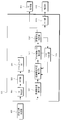
- FIG. 20 is a flowchart showing the operation of the receiving apparatus according to the third embodiment of the present invention.
- the operation shown in this figure is processing after the reception unit 405 in FIG. 18 outputs the reception signal to the search range determination unit 407.
- the search range determination unit 407 determines the previous path position and the search range for synchronization from the received signal (step S301). Thereafter, the process proceeds to step S302.
- the propagation path adaptability calculation unit 1303 Based on the preceding path position determined in step S301, the propagation path adaptability calculation unit 1303 generates a channel impulse response when one of the candidate paths is added to the paths previously determined by the path extraction unit 515. presume. This process is performed as many times as the number of candidate paths, and propagation path fitness is calculated for each (step S302).
- step S303 The unnecessary candidate path removal unit 511 removes, from the candidate paths, paths corresponding to the propagation path fitness obtained in step S302 that is lower than the propagation path fitness before adding one path (step S303). Thereafter, the process proceeds to step S304, and synchronization correction determination is performed.
- step S303 the synchronization correction determination unit 513 determines the shift amount to be applied to the synchronization position when there is no candidate path with a delay time smaller than the path with the smallest delay time among the extracted paths (step S304: Yes). Determine and proceed to step S306. Otherwise (step S304: No), the process proceeds to step S305.
- the path extraction unit 515 determines, as an extraction path, a path corresponding to the largest of the propagation path adaptability of candidate paths remaining as a result of step S303 (step S305). Thereafter, the process returns to step S302.
- the demapping unit 1209 separates data and pilot symbols from the received signal based on the synchronization position determined in step S304.
- a reception signal corresponding to the time when the separated pilot symbol is transmitted is output to propagation path estimation section 1205, and a reception signal corresponding to the time when data is transmitted is output to demodulation section 1207.
- propagation path estimation section 1205 estimates the channel impulse response and outputs it to demodulation section 1207 (step S306). Thereafter, the process proceeds to step S307.
- Demodulation section 1207 performs demodulation using the received signal corresponding to the time at which the data obtained in step S306 was transmitted and the channel impulse response estimated value (step S307). Thereafter, the process proceeds to step S308.
- the decoding unit 421 performs decoding using the demodulation result obtained in step S307 (step S308). Thereafter, the receiving apparatus 1201 ends the operation.
- the synchronization unit 1203 uses the received signal corresponding to the time when the pilot symbol is transmitted, deletes the path that cannot improve the propagation path suitability from the candidate paths, and transmits the propagation path.
- the process of extracting a path that improves the fitness is repeated, and the process is terminated when there are no candidate paths with a smaller delay time than those with the smallest delay time among the extracted paths.
- synchronization correction is performed.
- the reception device 401 according to the first embodiment may be used as a reception process for the signal transmitted by the transmission device 301 according to the present embodiment.
- the signal may be processed as a signal having a GI interval of 0.
- the transmission apparatus 1101 transmits a single carrier signal or the like that maps pilot symbols in the time domain, and the reception apparatus 1201 uses a reception signal corresponding to the time at which the pilot symbols are transmitted, and uses a channel impulse response.
- the path for improving the channel adaptability is selected one by one using the above estimation, and the synchronization correction amount is determined when the necessity of synchronization correction is determined.
- the transmission device according to the present embodiment has the same configuration as the transmission device 1101 according to the third embodiment, and thus description thereof is omitted.
- FIG. 21 is a schematic block diagram showing a configuration of a receiving device 1401 according to the fourth embodiment of the present invention.
- the receiving apparatus 1401 (FIG. 21) according to the present embodiment is compared with the receiving apparatus 1201 (FIG. 18) according to the third embodiment, the channel estimation unit 1205 is not provided, and the operation of the synchronization unit 1403 is the synchronization unit 1203. And different.
- the functions of other components (receiving antenna 403, receiving unit 405, search range determining unit 407, demapping unit 1209, demodulating unit 1207, and decoding unit 421) are the same as those in the third embodiment. A description of the same functions as those in the third embodiment is omitted.
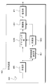
- FIG. 22 is a schematic block diagram showing the configuration of the synchronization unit 1403 according to the fourth embodiment of the present invention.
- the second embodiment is used instead of the synchronization correction determination unit 513 in the first embodiment. It has a synchronization correction determination unit 1001 in the form.
- the functions of the other components are the same as those in the third embodiment. A description of the same functions as those in the third embodiment is omitted.
- FIG. 23 is a flowchart showing the operation of the receiving apparatus according to the fourth embodiment of the present invention.
- the operation shown in this figure is processing after the receiving unit 405 in FIG. 21 outputs the received signal to the search range determining unit 407.
- the search range determination unit 407 determines a previous path position and a search range for synchronization from the received signal (step S401). Thereafter, the process proceeds to step S402.
- the propagation path adaptability calculation unit 1303 Based on the preceding path position determined in step S401, the propagation path adaptability calculation unit 1303 generates a channel impulse response when one of the candidate paths is added to the paths previously determined by the path extraction unit 515. presume.
- step S402 This process is performed as many times as the number of candidate paths, and propagation path suitability is calculated for each (step S402). Thereafter, the process proceeds to step S403.
- the unnecessary candidate path removal unit 511 removes, from the candidate paths, paths corresponding to the propagation path fitness obtained in step S402 that is lower than the propagation path fitness before adding one path (step S403). Thereafter, the process proceeds to step S404, and synchronization correction determination is performed.
- step S403 If the result of step S403 is that the remaining candidate paths become zero (step S404: Yes), the synchronization correction determination unit 1001 determines the shift amount to be applied to the synchronization position and demodulates the estimated channel impulse response estimation value. The data is output to the unit 1207, and the process proceeds to step S406. When that is not right (step S404: No), it progresses to step S405.
- the path extraction unit 515 determines, as an extraction path, a path corresponding to the largest of the propagation path adaptability of candidate paths remaining as a result of step S403 (step S405). Thereafter, the process returns to step S402.
- the demapping unit 1209 separates data and pilot symbols from the received signal based on the synchronization position determined in step S404.
- a reception signal corresponding to the time when the separated data is sent is output to demodulation section 1207.
- Demodulation section 1207 performs demodulation using this received signal and the channel impulse response estimated value obtained in step S404 (step S406). Thereafter, the process proceeds to step S407.
- the decoding unit 421 performs decoding using the demodulation result obtained in step S406 (step S407). Thereafter, the receiving apparatus 1401 ends the operation.
- the propagation path estimation is performed simultaneously with the processing of the synchronization section 1403, it is not necessary to have the propagation path estimation section, so that the circuit scale can be reduced.
- the transmitter 301 transmits a multicarrier signal or the like that maps pilot symbols in the frequency domain, and the receiver 401 first determines the frequency in the pilot subcarrier based on the determined search range and the preceding path position. A response estimation value is calculated, and a path for improving the channel adaptability is selected one by one using the estimation of the channel impulse response, and the synchronization amount is determined when the remaining candidate paths become zero.
- the transmission apparatus according to the present embodiment has the same configuration as the transmission apparatus 301 according to the first embodiment, and thus description thereof is omitted.
- FIG. 24 is a schematic block diagram illustrating a configuration of a reception device 1501 according to the fifth embodiment of the present invention. Comparing the receiving apparatus 1501 (FIG. 24) according to the present embodiment with the receiving apparatus 901 (FIG. 13) according to the second embodiment, the configuration of the search range determining unit 1503 is different, and a plurality of synchronizing units 903 are provided, A road suitability determination unit 1505 is added. However, the functions of other components (receiving antenna 403, receiving unit 405, GI removing unit 411, FFT unit 413, demapping unit 415, demodulating unit 419, decoding unit 421) are the same as those in the second embodiment. . A description of the same functions as those in the second embodiment is omitted.
- the search range determination unit 1503 sets a plurality of preceding path positions, and determines a search range for each as in the first to fourth embodiments. This setting method is, for example, as shown in FIG.
- FIG. 25 is a diagram for explaining a setting method for setting a plurality of preceding path positions according to the fifth embodiment of the present invention.
- two types of search ranges are set.
- the position 1601 is the head of the first search range
- the position 1603 is the first preceding path position
- the position 1605 is the end of the first search range.
- a position 1611 represents the head of the first search range
- a position 1613 represents the first preceding path position
- a position 1615 represents the end of the first search range.
- a plurality of synchronization units 903 perform the same processing as in the second embodiment on the plurality of search ranges output by the search range determination unit 1503.
- the propagation path match determination unit 1505 selects the one with the highest propagation path match input from the plurality of synchronization units 903, outputs the corresponding synchronization position to the GI removal unit 411, and demodulates the channel impulse response estimation value. Output to.
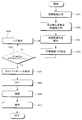
- FIG. 26 is a flowchart showing the operation of the receiving apparatus according to the fifth embodiment of the present invention.
- the operation shown in this figure is processing after the receiving unit 405 in FIG. 24 outputs the received signal to the search range determining unit 1503.
- Search range determining section 1503 determines a plurality of preceding path positions and a search range for synchronization from the received signal (step S501). Thereafter, the process proceeds to step S502.
- the plurality of frequency response estimators 507 estimate the frequency response of the pilot subcarriers using the received signals that have been time-frequency converted based on the plurality of preceding path positions determined in step S501 to obtain frequency response estimated values (step S502). Thereafter, the process proceeds to step S503.
- the plurality of propagation path fitness calculation units 509 use one of the candidate paths in addition to the paths determined so far by the corresponding path extraction unit 515 using the plurality of frequency response estimation values obtained in step S502.
- the channel impulse response is estimated. This process is performed as many times as the number of candidate paths, and the channel adaptability is calculated (step S503). Thereafter, the process proceeds to step S504.
- the plurality of unnecessary candidate path removal units 511 remove, from the candidate paths, paths corresponding to those that are less than the corresponding channel match before adding one path among the plurality of channel match obtained in step S503. (Step S504). Thereafter, the process proceeds to step S505.
- the plurality of synchronization correction determination units 1001 determine the shift amount to be applied to the synchronization position and output it to the propagation path adaptation determination unit 1505.
- the estimated channel impulse response estimated value is output to the propagation path match determination unit 1505, and the operation ends. If all the synchronization correction determination units 1001 have finished their operations (step S505: Yes), the process proceeds to step S507.
- step S505 When that is not right (step S505: No), it progresses to step S506.
- the plurality of path extraction units 515 determine, as an extraction path, a path corresponding to the largest of the propagation path adaptability of candidate paths remaining as a result of step S504 (step S506). Thereafter, the process returns to step S503.
- the propagation path adaptation determination unit 1505 outputs the synchronization position corresponding to the largest one of the plurality of propagation path adaptations obtained as a result of step S505 to the GI removal unit 411, and the channel impulse response estimated value is the frequency response estimated value. And then output to the demodulator 419 (step S507). Thereafter, the process proceeds to step S508.
- the GI removal unit 411 removes the guard interval from the received signal based on the synchronization position determined in step S507 (step S508). Thereafter, the process proceeds to step S509.
- the FFT unit 413 performs time-frequency conversion on the signal obtained in step S508 (step S509).
- the demapping unit 415 separates data and pilot symbols from the obtained frequency domain signal.
- step S510 Demodulation section 419 performs demodulation using the received data subcarrier signal obtained in step S509 and the demodulation frequency response estimation value obtained in step S507 (step S510). Thereafter, the process proceeds to step S511.
- the decoding unit 421 performs decoding using the demodulation result obtained in step S510 (step S511). Thereafter, the receiving apparatus 1501 ends the operation.
- a plurality of synchronization units determine a synchronization position, and a position that can improve transmission characteristics is selected as the synchronization position by selecting the largest one of the propagation path suitability levels. be able to.
- a part of the transmission devices 301 and 1101 and the reception devices 401, 901, 1201, and 1301, for example, the synchronization unit 409 and the demodulation unit 419 in the above-described embodiment may be realized by a computer.
- a program for realizing this control function may be recorded on a computer-readable recording medium, and the program recorded on this recording medium may be read into a computer system and executed.
- the “computer system” here is a computer system built in the transmission apparatuses 301 and 1101 or the reception apparatuses 401, 901, 1201, and 1301, and includes hardware such as an OS and peripheral devices.
- the “computer-readable recording medium” refers to a storage device such as a portable medium such as a flexible disk, a magneto-optical disk, a ROM, and a CD-ROM, and a hard disk built in the computer system.
- the “computer-readable recording medium” is a medium that dynamically holds a program for a short time, such as a communication line when transmitting a program via a network such as the Internet or a communication line such as a telephone line,
- a volatile memory inside a computer system serving as a server or a client may be included and a program that holds a program for a certain period of time.
- the program may be a program for realizing a part of the functions described above, and may be a program capable of realizing the functions described above in combination with a program already recorded in a computer system.
- a part or all of the transmission devices 301 and 1101 and the reception devices 401, 901, 1201, and 1301 in the above-described embodiments may be realized as an integrated circuit such as an LSI (Large Scale Integration).
- LSI Large Scale Integration
- Each functional block of the transmission device 301 and the reception devices 401, 901, and 1201 may be individually made into a processor, or a part or all of them may be integrated into a processor.
- the method of circuit integration is not limited to LSI, and may be realized by a dedicated circuit or a general-purpose processor. Further, in the case where an integrated circuit technology that replaces LSI appears due to progress in semiconductor technology, an integrated circuit based on the technology may be used.
Landscapes
- Engineering & Computer Science (AREA)
- Computer Networks & Wireless Communication (AREA)
- Signal Processing (AREA)
- Power Engineering (AREA)
- Noise Elimination (AREA)
Abstract
高精度な同期位置確定を可能とする。受信したマルチパスから先行パス位置を決定する受信装置であって、周波数応答推定値を用いてチャネルインパルス応答を推定し、その推定値とパスとの適合度を示す伝搬路適合度をパス毎に算出する伝搬路適合度算出部509と、前記伝搬路適合度を向上できない候補パスを除去する不要候補パス除去部511と、前記伝搬路適合度を向上させる候補パスを少なくとも一つ抽出して抽出パスとするパス抽出部515と、前記抽出パスのうち、最も遅延時間が小さい候補パスの時間的位置を先行パス位置に決定する同期補正判定部513と、を備える。
Description
本発明は、受信装置の高精度な同期位置確定方法に関する。
無線通信においては、特に広帯域伝送の場合、先行して受信するパスに加え、建物や山などの障害物からの反射を経由する等して遅延して到来するパスが存在する。このように複数のパスが到来する環境をマルチパス環境という。受信装置が受信信号に対して復調処理を行なう場合は、最初に到来するパスに同期することが望ましい。
非特許文献1には、OFDM(Orthogonal Frequency Division Multiplexing;直交周波数分割多重)において、ガードインターバル(Guard Interval;GI)を超える遅延パスがある場合でも高精度に同期を行なえる方法が記載されている。その方法は、まず受信信号を用いて自己相関を計算し、ピークの値に事前に定められた値を乗算したものを閾値とし、それを上回る遅延時間最小のパスを仮タイミングとする。次に、その位置から遅延時間の少し小さい位置を先頭とし、遅延時間の大きい領域にもある程度の長さを持った区間を設定し、その区間に対してチャネルインパルス応答の推定を行なう。ただし、チャネルインパルス応答とは、時間領域の伝搬路のことをいう。推定されたチャネルインパルス応答のピーク値に事前に定められた値を乗算したものを閾値とし、それを上回る遅延時間最小のパスを同期位置として決定する。
図27は、自己相関に基づいて、チャネルインパルス応答の推定を行ない、これにより同期位置を決定する一例を示す図である。図27において、上段は自己相関を表わす。ピークのパス101により、閾値103が決まる。閾値103を超える遅延時間最小のパスがパス105なので、ここではパス105を仮タイミングとして決定する。次に、図27下段は、パス105の位置から決まる探索範囲において推定したチャネルインパルス応答を表わす。パス201~215はチャネルインパルス応答を構成するパスであり、ピークのパス201を有する。これにより閾値217が決まる。閾値217を超える遅延時間最小のパスがパス203なので、パス203を先行パスとして同期位置を決定する。
静野、須山、鈴木、府川、「OFDMパケット伝送におけるチャネル推定を用いた高精度タイミング再生」、電子情報通信学会技術報告、RCS2003-124、2003年8月
しかしながら、非特許文献1の方法では、サブキャリアが多いシステムなど探索範囲が非常に大きくなる場合、雑音強調で推定値の真値からの誤差が大きくなり、同期位置の精度が劣化してしまう。本発明は、このような事情に鑑みてなされたものであり、高精度な同期位置確定が可能な受信装置、受信方法、制御プログラムおよび集積回路を提供することを目的とする。
(1)上記の目的を達成するために、本発明は、以下のような手段を講じた。すなわち、本発明の受信装置は、受信したマルチパスから先行パス位置を決定する受信装置であって、周波数応答推定値を用いてチャネルインパルス応答を推定し、その推定値とパスとの適合度を示す伝搬路適合度をパス毎に算出する伝搬路適合度算出部と、前記伝搬路適合度を向上できない候補パスを除去する不要候補パス除去部と、前記伝搬路適合度を向上させる候補パスを少なくとも一つ抽出して抽出パスとするパス抽出部と、前記抽出パスのうち、最も遅延時間が小さい候補パスの時間的位置を先行パス位置に決定する同期補正判定部と、を備えることを特徴としている。
このように、受信装置は、伝搬路適合度を向上できない候補パスを除去し、伝搬路適合度を向上させる候補パスを少なくとも一つ抽出して抽出パスとし、抽出パスのうち、最も遅延時間が小さい候補パスの時間的位置を先行パス位置に決定するので、パスを選んで推定でき、雑音や干渉の低減効果が増加し、雑音強調を抑えることができる。
(2)また、本発明の受信装置において、前記受信したマルチパスから仮先行パス位置を決定し、前記決定した仮先行パス位置を基準として先行パスの探索範囲を決定する探索範囲決定部を備えることを特徴としている。
このように、受信装置は、受信したマルチパスから仮先行パス位置を決定し、決定した仮先行パス位置を基準として先行パスの探索範囲を決定するので、ガードインターバル(Guard Interval;GI)を超える遅延パスがある場合でも高精度に同期を行なえる。
(3)また、本発明の受信装置において、前記探索範囲決定部は、前記仮先行パス位置よりも遅延時間が小さい位置を前記探索範囲の先頭とすることを特徴としている。
このように、受信装置は、仮先行パス位置よりも遅延時間が小さい位置を探索範囲の先頭とするので、ガードインターバル(Guard Interval;GI)を超える遅延パスがある場合でも高精度に同期を行なえる。
(4)また、本発明の受信装置において、前記探索範囲決定部は、前記仮先行パス位置よりも遅延時間が大きい位置を前記探索範囲の終端とすることを特徴としている。
このように、受信装置は、仮先行パス位置よりも遅延時間が大きい位置を探索範囲の終端とするので、ガードインターバル(Guard Interval;GI)を超える遅延パスがある場合でも高精度に同期を行なえる。
(5)また、本発明の受信装置において、前記探索範囲決定部は、前記仮先行パス位置よりも遅延時間が最大遅延時間だけ大きい位置を前記探索範囲の終端とすることを特徴としている。
このように、受信装置は、仮先行パス位置よりも遅延時間が最大遅延時間だけ大きい位置を前記探索範囲の終端とするので、ガードインターバル(Guard Interval;GI)を超える遅延パスがある場合でも高精度に同期を行なえる。
(6)また、本発明の受信装置において、情報量基準を前記伝搬路適合度として用いることを特徴としている。
このように、受信装置は、情報量基準を伝搬路適合度として用いるので、パスを選んで推定でき、雑音や干渉の低減効果が増加し、雑音強調を抑えることができる。
(7)また、本発明の受信装置において、前記情報量基準は、ベイズ情報量基準であることを特徴としている。
このように、情報量基準が、ベイズ情報量基準であるので、受信装置は、パスを選んで推定でき、雑音や干渉の低減効果が増加し、雑音強調を抑えることができる。
(8)また、本発明の受信装置において、受信信号を時間領域の信号から周波数領域の信号に変換する時間周波数変換部と、前記周波数領域の受信信号と参照信号とを用いて周波数領域の伝搬路である周波数応答を推定し、周波数応答推定値を出力する周波数応答推定部と、を備え、前記伝搬路適合度算出部は、前記周波数応答推定値を用いて前記伝搬路適合度を算出することを特徴としている。
このように、受信装置は、周波数応答推定値を用いて伝搬路適合度を算出するので、パスを選んで推定でき、雑音や干渉の低減効果が増加し、雑音強調を抑えることができる。
(9)また、本発明の受信装置において、前記伝搬路適合度算出部は、参照信号がマッピングされた時刻に対応する受信信号を用いて前記チャネルインパルス応答を推定することを特徴としている。
このように、受信装置が、参照信号がマッピングされた時刻に対応する受信信号を用いて前記チャネルインパルス応答を推定するので、送信装置は、時間領域で連続した信号を送信するシングルキャリア送信を行ない、その中で時間的に連続したパイロットシンボルを挿入し、そのパイロットシンボルを参照信号として同期補正を行なうことができる。
(10)また、本発明の受信装置において、前記同期補正判定部は、前記抽出パスのうち、遅延時間が最小であるパスよりも遅延時間が小さい候補パスが存在しないことを検出した場合、前記先行パス位置の決定を行なうことを特徴としている。
このように、受信装置は、抽出パスのうち、遅延時間が最小であるパスよりも遅延時間が小さい候補パスが存在しないことを検出した場合、先行パス位置の決定を行なうので、パスを選んで推定でき、雑音や干渉の低減効果が増加し、雑音強調を抑えることができる。
(11)また、本発明の受信装置において、前記同期補正判定部は、前記伝搬路適合度を向上できない候補パスを除去した結果、候補パスが無くなった場合、前記先行パス位置の決定を行なうことを特徴としている。
このように、受信装置は、伝搬路適合度を向上できない候補パスを除去した結果、候補パスが無くなった場合、前記先行パス位置の決定を行なうので、パスを選んで推定でき、雑音や干渉の低減効果が増加し、雑音強調を抑えることができる。
(12)また、本発明の受信装置において、前記抽出パスから構成されるチャネルインパルス応答推定値を時間領域の信号から周波数領域の信号に変換し、周波数応答推定値を出力する伝搬路用時間周波数変換部を備えることを特徴としている。
このように、受信装置は、抽出パスから構成されるチャネルインパルス応答推定値を時間領域の信号から周波数領域の信号に変換し、周波数応答推定値を出力するので、回路規模を削減することができる。
(13)また、本発明の受信装置において、前記伝搬路適合度算出部、前記不要候補パス除去部、前記パス抽出部および前記同期補正判定部を有する複数の同期部と、前記各同期部から得られる伝搬路適合度のうち、最も大きい伝搬路適合度に対応するパス位置を先行パス位置に決定する伝搬路適合判定部と、を備えることを特徴としている。
このように、受信装置は、各同期部から得られる伝搬路適合度のうち、最も大きい伝搬路適合度に対応するパス位置を先行パス位置に決定するので、伝搬路適合度を最も大きくする同期位置とチャネルインパルス応答推定値を採用することができる。
(14)また、本発明の受信方法は、受信したマルチパスから先行パス位置を決定する受信方法であって、周波数応答推定値を用いてチャネルインパルス応答を推定し、その推定値とパスとの適合度を示す伝搬路適合度をパス毎に算出するステップと、前記伝搬路適合度を向上できない候補パスを除去するステップと、前記伝搬路適合度を向上させる候補パスを少なくとも一つ抽出して抽出パスとするステップと、前記抽出パスのうち、最も遅延時間が小さい候補パスの時間的位置を先行パス位置に決定するステップと、を少なくとも含むことを特徴としている。
このように、受信装置は、伝搬路適合度を向上できない候補パスを除去し、伝搬路適合度を向上させる候補パスを少なくとも一つ抽出して抽出パスとし、抽出パスのうち、最も遅延時間が小さい候補パスの時間的位置を先行パス位置に決定するので、パスを選んで推定でき、雑音や干渉の低減効果が増加し、雑音強調を抑えることができる。
(15)また、本発明の制御プログラムは、受信したマルチパスから先行パス位置を決定する受信装置の制御プログラムであって、周波数応答推定値を用いてチャネルインパルス応答を推定し、その推定値とパスとの適合度を示す伝搬路適合度をパス毎に算出する処理と、前記伝搬路適合度を向上できない候補パスを除去する処理と、前記伝搬路適合度を向上させる候補パスを少なくとも一つ抽出して抽出パスとする処理と、前記抽出パスのうち、最も遅延時間が小さい候補パスの時間的位置を先行パス位置に決定する処理と、の一連の処理を、コンピュータに実行させることを特徴としている。
このように、受信装置は、伝搬路適合度を向上できない候補パスを除去し、伝搬路適合度を向上させる候補パスを少なくとも一つ抽出して抽出パスとし、抽出パスのうち、最も遅延時間が小さい候補パスの時間的位置を先行パス位置に決定するので、パスを選んで推定でき、雑音や干渉の低減効果が増加し、雑音強調を抑えることができる。
(16)また、本発明の集積回路は、受信装置に実装されることにより、前記受信装置に複数の機能を発揮させる集積回路であって、マルチパスを受信する機能と、周波数応答推定値を用いてチャネルインパルス応答を推定し、その推定値とパスとの適合度を示す伝搬路適合度をパス毎に算出する機能と、前記伝搬路適合度を向上できない候補パスを除去する機能と、前記伝搬路適合度を向上させる候補パスを少なくとも一つ抽出して抽出パスとする機能と、前記抽出パスのうち、最も遅延時間が小さい候補パスの時間的位置を先行パス位置に決定する機能と、の一連の機能を、前記受信装置に発揮させることを特徴としている。
このように、受信装置は、伝搬路適合度を向上できない候補パスを除去し、伝搬路適合度を向上させる候補パスを少なくとも一つ抽出して抽出パスとし、抽出パスのうち、最も遅延時間が小さい候補パスの時間的位置を先行パス位置に決定するので、パスを選んで推定でき、雑音や干渉の低減効果が増加し、雑音強調を抑えることができる。
この発明によれば、同期の精度を大きく向上することができる。
図27のマルチパスに関して補足説明する。FFTポイント数をN、サブキャリア間隔をΔfとしたとき、各パスの時間間隔は1/(NΔf)とするのが一般的で、本発明でもそのように仮定している。
図28は、Naのサブキャリアからなる送信信号を表す図である。Δfはシステムによって決まっている値でLTE(第3.9世代移動通信システム)なら15kHzとなる。この信号が送信側から送信され、伝搬路を通って受信側に送られる。なお、NはNaより大きい整数であれば良いが、FFTの性質上、2のべき乗とするのが一般的である(2のべき乗が最も速く計算可能)。受信機で受信される信号は当然アナログ信号(連続)であるので、ディジタル信号処理を行なえるようにするため、フィルタリングおよびAD変換を行なう。
図29は、アナログの受信信号を時間間隔Δtでサンプリングした様子を表わす図である。Δtは1/(NΔf)に当たる。本明細書では、遅延パスの遅延時間はΔtの整数倍で扱えるものとしてモデル化する。従って、例えばLTEでNを2048としたとき、パス間隔は0.0326μsとなる。以下、本発明の実施形態について図面を参照して説明する。
(第1の実施形態)
図1は、本発明の第1の実施形態に係る送信装置の概略ブロック図である。以下、本実施形態に係る送信装置を送信装置301という。この図において、送信装置301は、パイロット生成部303、符号部305、変調部307、マッピング部309、IFFT部(周波数時間変換部とも呼ぶ)311、GI挿入部313、送信部315、および送信アンテナ317を含んで構成され、OFDM信号を送信する。パイロット生成部303は、受信装置がその波形(あるいは、その信号系列)の振幅値を予め記憶するパイロットシンボルを生成し、マッピング部309に出力する。なお、以下、本実施形態では、受信装置を受信装置401という。受信装置401では、パイロットシンボルを参照信号として伝搬路推定や同期を行なう。符号部305は、受信装置401に送信する情報ビットに対して畳込み符号、ターボ符号、LDPC(Low Density Parity Check:低密度パリティ検査)符号などの誤り訂正符号を用いて符号化し、符号化ビットを生成する。符号部305は、生成した符号化ビットを変調部307に出力する。
図1は、本発明の第1の実施形態に係る送信装置の概略ブロック図である。以下、本実施形態に係る送信装置を送信装置301という。この図において、送信装置301は、パイロット生成部303、符号部305、変調部307、マッピング部309、IFFT部(周波数時間変換部とも呼ぶ)311、GI挿入部313、送信部315、および送信アンテナ317を含んで構成され、OFDM信号を送信する。パイロット生成部303は、受信装置がその波形(あるいは、その信号系列)の振幅値を予め記憶するパイロットシンボルを生成し、マッピング部309に出力する。なお、以下、本実施形態では、受信装置を受信装置401という。受信装置401では、パイロットシンボルを参照信号として伝搬路推定や同期を行なう。符号部305は、受信装置401に送信する情報ビットに対して畳込み符号、ターボ符号、LDPC(Low Density Parity Check:低密度パリティ検査)符号などの誤り訂正符号を用いて符号化し、符号化ビットを生成する。符号部305は、生成した符号化ビットを変調部307に出力する。
変調部307は、符号部305から入力された符号化ビットを、PSK(Phase Shift Keying:位相偏移変調)やQAM(Quadrature amplitude modulation:直交振幅変調)などの変調方式を用いて変調し、変調シンボルを生成する。変調部307は、生成した変調シンボルをマッピング部309に出力する。マッピング部309は、パイロット生成部303から入力されたパイロットシンボル、および変調部307から入力された変調シンボルを、予め定められたマッピング情報に基づいてリソース(時間-周波数帯域)にマッピングして周波数領域の信号を生成し、生成した周波数領域の信号をIFFT部311に出力する。なお、リソースとは、送信装置301が送信するフレームにおいて1つのサブキャリアと1つの後述するFFT区間から成る、変調シンボルを配置する単位である。また、マッピング情報は、送信装置301が決定し、送信装置301から受信装置401へ予め通知される。
図2は、マッピング部309がパイロットシンボルと変調信号をマッピングする例を示す図である。IFFT部311は、マッピング部309から入力された周波数領域の信号を周波数-時間変換し、時間領域の信号を生成する。ここで、IFFTを行なう単位の時間区間をFFT区間という。IFFT部311は、生成した時間領域の信号をGI挿入部313に出力する。GI挿入部313は、IFFT部311から入力された時間領域の信号に対して、FFT区間の信号毎にガードインターバル(Guard Interval:GI)を付加する。ここで、ガードインターバルとは、FFT区間の信号の後方の一部を複製したものであるサイクリックプレフィックス(Cyclic Prefix:CP)やゼロ区間が続くゼロパディング、Golay符号等を用いた既知信号等であり、GI挿入部313は、このような信号をこのFFT区間の信号の前方に付加する。
なお、FFT区間と、GI挿入部313がその時間区間の信号に付加したガードインターバルの時間区間(GI区間という)と、を併せてOFDMシンボル区間という。また、OFDMシンボル区間の信号をOFDMシンボルという。GI挿入部313は、ガードインターバルを付加した信号を送信部315に出力する。なお、ガードインターバルをFFT区間の後方に挿入してもよい。例えば、サイクリックプレフィックスを用いる場合、FFT区間の前方の一部の複製をFFT区間の信号の後方に付加する。また、サイクリックプレフィックスの場合は、OFDMシンボル区間で周期性が保たれるようにすればよく、前記の限りではない。送信部315は、GI挿入部313から入力された信号をディジタル・アナログ変換し、変換したアナログ信号を波形整形する。送信部315は、波形整形した信号をベースバンド帯から無線周波数帯にアップコンバートし、送信アンテナ317から受信装置401へ送信する。
図3は、本発明の第1の実施形態に係る受信装置401の構成を示す概略ブロック図である。この図において、受信装置401は、受信アンテナ403、受信部405、探索範囲決定部407、同期部409、GI除去部411、FFT部(時間周波数変換部とも呼ぶ)413、デマッピング部415、伝搬路推定部417、復調部419、復号部421を含んで構成される。受信部405は、送信装置301が送信した送信信号を、受信アンテナ403を介して受信する。受信部405は、受信した信号に対して、周波数変換およびアナログ-ディジタル変換を行なう。探索範囲決定部407は、受信部405から入力される受信信号から、パスの探索範囲を決定する。この具体的な処理は動作原理と併せて後述する。
同期部409は、探索範囲決定部407が決定した探索範囲において、パイロットシンボルが送信されたサブキャリアの受信信号とパイロットシンボルを用いて、伝搬路適合度を向上させるパスを検出することで同期を行なう。同期部409に関しては、図面を用いて詳細を後述する。結果はGI除去部411に出力する。GI除去部411は、受信部405から入力される受信信号と、同期部409から入力される同期情報を用い、受信信号から、ガードインターバルを除去し、FFT部413へ出力する。FFT部413は、GI除去部411から入力された時間領域の信号に対して時間周波数変換を行ない、変換した周波数領域の信号をデマッピング部415へ出力する。デマッピング部415は、送信装置301から予め通知されたマッピング情報に基づいてデマッピングし、分離されたパイロットシンボルが送信されたサブキャリアの受信信号を伝搬路推定部417に出力する。また、データが送信されたサブキャリアの受信信号を復調部419に出力する。
伝搬路推定部417は、パイロットシンボルが送信されたサブキャリアの受信信号とパイロットシンボルを用いて復調用周波数応答推定値を算出し、復調部419に出力する。手法には最小二乗法やMMSE(Minimum Mean Square Error)、DFT(Discrete Fourier Transform)法等の既知技術を用いればよい。また、伝搬路推定部417は、予め記憶するパイロットシンボルを用い、パイロットシンボルが配置されるサブキャリア(パイロットサブキャリアという)において、雑音電力を測定する。具体的な算出方法は、動作原理と併せて後述する。復調部419は、伝搬路推定部417から入力された復調用周波数応答推定値および雑音電力を用いて、ZF(Zero Forcing)基準、MMSE基準等のフィルタ係数を算出する。復調部419は、算出したフィルタ係数を用いて、信号の振幅と位相の変動の補償(伝搬路補償という)を行なう。復調部419は、復調処理の結果のビット対数尤度比(LLR;Log Likelihood Ratio)を復号部421に出力する。
復号部421は、復調部419から入力された復調シンボルに対して、例えば、最尤復号法(MLD;Maximum Likelihood Decoding)、最大事後確率(MAP;Maximum A posteriori Probability)、log-MAP、Max-log-MAP、SOVA(Soft Output Viterbi Algorithm)等を用いて、復号処理を行なう。
図4は、本発明の第1の実施形態に係る同期部409の構成を示す概略ブロック図である。同期部409は、GI除去部501、FFT部503、デマッピング部505、周波数応答推定部507、伝搬路適合度算出部509、不要候補パス除去部511、同期補正判定部513、パス抽出部515から構成される。この具体的な処理は動作原理と併せて後述する。
<動作原理について>
以下、受信装置401の動作原理について、図3を参照しながら説明する。受信部405が受信した第k離散時刻の第iシンボルの受信信号ri,kは、次式(1)、(2)で表わされる。
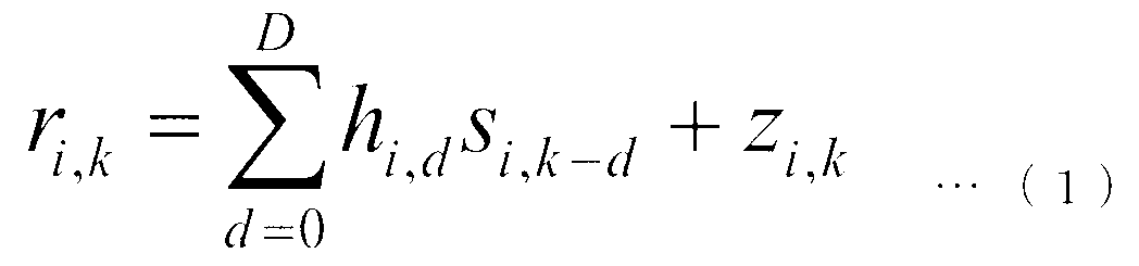

以下、受信装置401の動作原理について、図3を参照しながら説明する。受信部405が受信した第k離散時刻の第iシンボルの受信信号ri,kは、次式(1)、(2)で表わされる。
ここで、Dは最大遅延時間、hi,dは第iシンボルの伝搬路番号dのパス(第dパスという)における複素振幅、si,kは第iシンボル第k離散時刻の時間領域の送信信号であり、zi,kは第iシンボルの時間領域の雑音である。また、NはFFT区間のポイント数、Si,nは第nサブキャリアの第iシンボルの変調信号、NgはGI区間のポイント数(後述する図6参照)、jは虚数単位である。なお、d=0~Dの複素振幅をまとめて、チャネルインパルス応答という。
なお、受信部405が受信した時点では、同期が確立されていないため、そのポイントがどのシンボルのどの離散時刻のポイントなのかは分からない。そこで、この時点での受信信号をruとする。探索範囲決定部407では、ruを用いてガードインターバル相関や参照信号の時間波形との相関を用い、先行パスの位置を特定する。ガードインターバル相関を用いる場合、相関ρτは次式(3)のようになる。

また、参照信号を用いる場合、相関ρτは次式(4)のようになる。
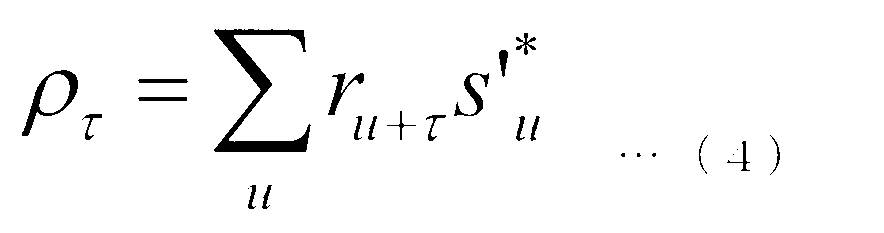
式(3)、(4)において、和の幅は、相関が充分取れる範囲で行なえばよい。例えば、1OFDMシンボル分の和でもよいし、受信装置401を設計した段階で固定にしてもよいし、受信装置401のファームウェア、ソフトウェア等をアップデートするときに更新する等してもよい。
図5は、本発明の第1の実施形態に係る探索範囲決定部407で、先行パスの位置を特定するのに用いられる相関ρτを示す図である。パス601~619は相関の強く出ている部分であり、パスの候補となる。実際には雑音も存在するため、これ以外の位置にも微小な値が存在する。図5ではパス601が先行パスと考えられ、この位置、あるいはさらに前の時間にも観測できなかったパスが存在する可能性を考慮してさらに前にオフセットした位置を先行パス位置とする。このオフセット量は受信装置401を設計した段階で固定にしてもよいし、受信装置401のファームウェア、ソフトウェア等をアップデートするときに更新する等してもよい。またオフセット量は0でも良い。なお、非特許文献1のように、ピーク値から閾値を算出し、それを上回る遅延時間最小のパスを先行パス位置としてもよいし、このようにして求めた位置のさらに前にオフセットした位置を先行パス位置としてもよい。なお、このようにして決めた先行パス位置を仮先行パス位置と呼ぶ。
探索範囲決定部407は、この後同期を行なうための探索範囲も決定する。具体的には、ここで決めた先行パス位置からTだけ遅延時間の小さい位置から、Lだけ遅延時間の大きい位置、すなわち、遅延時間-T~Lを探索範囲とする。具体的なTやLの値は、受信装置を設計する段階で決めておいてもよいし、設計段階では可変にしておき、受信装置のファームウェア、ソフトウェア等をアップデートするときに更新する等してもよい。すなわち、Tは0でもよい。Lは、最大遅延時間をカバーできる程度に大きいことが望ましいが、Tと同程度の値でもよい。
次に図4を参照しながら同期部409の動作を説明する。まず、GI除去部501において、探索範囲決定部407が決定した先行パス位置に基づいて受信信号からGIを除去し、受信信号のFFT区間を抽出する。その後、FFT部503において、受信信号のFFT区間に時間周波数変換を行ない、周波数領域の受信信号に変換する。このとき、探索範囲決定部407で決めた先行パス位置が真の位置よりNeポイント前であったとすると、第iシンボル第nサブキャリアの信号Ri,nは次式(5)で表わされる。
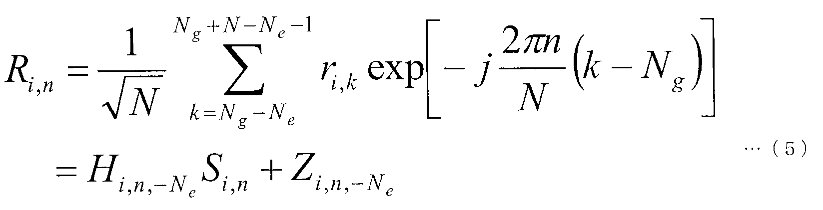
ただし、Zi,n,-Neは周波数領域の雑音である。また、Hi,n,-Neは第iシンボル第nサブキャリアの周波数応答であり、次式(6)、(7)のようになる。

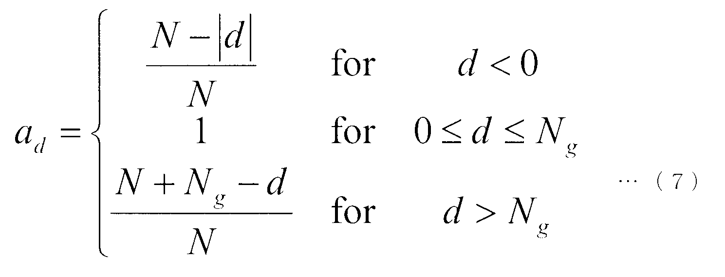
なお、Neポイント前にずれたことにより、D+Ne>Ngとなった場合、ISIおよびICIが発生し、式(5)のZi,n,-Neが雑音だけでなく、ISIおよびICIも加算されたものとなる。図6にこの様子を示す。
図6は、本発明の第1の実施形態に係る探索範囲決定部407で決めた先行パス位置が真の位置よりNeポイント前であったとした場合に、第iシンボル第nサブキャリアの信号Ri,nを表す式(5)、(6)において、Ng=3、D=3、Ne=-1としたときの例を示す図である。Neだけずれた結果、第3パスの部分701がガードインターバルを超える遅延波として観測され、ISIおよびICIが発生する。このため、伝送特性が劣化する。
次に、Neポイント後ろにずれた場合について説明する。第iシンボル第nサブキャリアの信号Ri,nは次式(8)、(9)で表わされる。


図7にこの様子を示す。図7は、本発明の第1の実施形態に係る探索範囲決定部407で決めた先行パス位置が真の位置よりNeポイント後ろにずれた場合に、第iシンボル第nサブキャリアの信号Ri,nを表す式(8)、(9)において、Ng=3、D=3、Ne=1としたときの例を示す図である。Neだけ後ろにずれた結果、先行パスの部分801が異なるOFDMシンボルであるため、ISIおよびICIが発生する。このため、伝送特性が劣化する。実際には真の先行パス位置からのずれは未知であるため、第iシンボル第nサブキャリアの周波数応答をHi,nとして説明する。Hi,nからのチャネルインパルス応答の推定を利用して同期を行なう。ここで、周波数応答推定値からチャネルインパルス応答を推定する方法について説明する。n1、n2、・・・、nPをパイロットサブキャリアとし、周波数応答推定ベクトルHi,Pを次式(10)のように定義する。

ただし、太字はベクトルまたは行列を表わし、YTはYの転置を表わす。なお、例えば図2における最初のOFDMシンボルを考えると、n1は一番低いサブキャリア、n2はそれより2つ先のサブキャリア、n3はさらに2つ先のサブキャリア、・・・、ということになる。このとき、MMSEによるチャネルインパルス応答推定ベクトルhi,MMSEは、次式(11)~(14)のようになる。

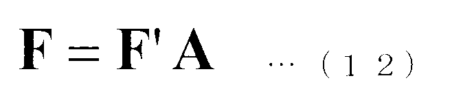

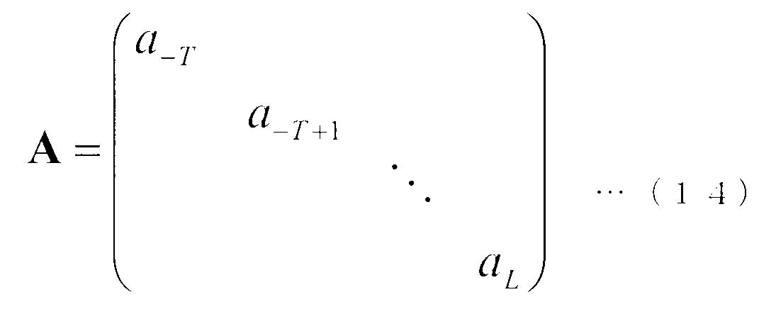
ただし、NPはパイロットサブキャリア数であり、Ixはサイズxの単位行列である。また、遅延時間-T~Lは探索範囲を表わし、探索範囲決定部407が先行パス位置を決めることで定まる。先行パス位置より負の遅延時間も考慮しており、-Tまで考慮する。また、Lは想定する最大遅延時間である。なお、Ci,hは主対角要素に、-T~Lまでのパスの平均電力の値を持つサイズL+T+1の対角行列である。平均電力は未知のため、一定値αとする。ただし、伝搬路適合度を向上するパスだけをαとし、それ以外は0とする。ここで、伝搬路適合度とは、計算した推定値と観測したデータ(ここでは受信信号)の適合度合いを定量的に表わす量である。
図8は、本発明の第1の実施形態に係る各パスの平均電力を示す図である。例えば、図8のようにT=2、L=5のもとで遅延時間0、1、3のパスだけを推定する場合、Ci,hは次式(15)のようになる。

同期部409では、詳細は後述するが、例えば、伝搬路適合度を向上するパスが負の遅延時間に相当する部分(-T~-1に対応する部分)にあった場合、先行パス位置を探索範囲決定部407が決めたものより検出した分だけシフトする。また、伝搬路適合度を向上する最も遅延時間の小さいパスが正の遅延時間にあった場合もシフトを行なう。伝搬路適合度算出部509では、周波数応答推定部507から入力される周波数応答推定値を用い、それまでに抽出されているパスに加えて、候補パスのうち1パスを増やしてチャネルインパルス応答を推定する。これを全候補パスについて行ない、それぞれ伝搬路適合度を算出する。ただし、初回の処理では抽出されているパスが存在しないため、全候補パスによる1パス推定を行なって伝搬路適合度を算出する。
図9は、本発明の第1の実施形態に係る全候補パスによる1パス推定を説明するための図である。例えば、T=2、L=5で初回の処理の場合、図9のように8通りの伝搬路適合度を算出することになる。この結果を不要候補パス除去部511に出力する。不要候補パス除去部511では、伝搬路適合度算出部509からの入力のうち、パスを増やす前の伝搬路適合度を下回ったパスを候補パスから削除する。ただし、初回の処理の場合はパスを増やす前の伝搬路適合度が存在しないため、この削除処理は行なわない。同期補正判定部513では、抽出した最も遅延時間の小さいパスより遅延時間の小さい候補パスがなくなったことを検出した場合、同期部409の処理を終了させる。
図10A~10Cは、本発明の第1の実施形態に係る同期部409の処理が終了した後の各パスの平均電力を示す図である。後述するが、図10においては、同期部409の処理が終了した後に3パス選ぶ場合を示している。図10A~10Cにおいて、パスの立っている位置はそれまでの処理で抽出されたパスを表わし、×のついた位置は削除された候補パスを表わす。図10Aは、探索範囲決定部407が決めた同期位置と同じパスが先行パスとなる場合の例であり、この場合は同期位置は変わらない。図10Bは、負の遅延時間にパスを検出した場合の例であり、図7のような問題が起こっていると考えられ、同期位置をシフトする。そのシフト量(ここでは-1)を加えてGI除去部411に出力する。図10Cは、正の方向に同期がずれていたことを検出した場合の例である。上述してきた通り、図6のような問題の発生が起こりうるため、この場合もシフトを行なう。そのシフト量(ここでは1)をGI除去部411に出力する。なお、抽出した最も遅延時間の小さいパスより遅延時間の小さい候補パスが残っている場合、同期補正判定部513は特に動作をせず、パス抽出部515に移行する。
パス抽出部515では、不要候補パス除去部511で除去されなかった候補パスのうち、伝搬路適合度を最も大きくするパスを抽出する。抽出したパス位置は候補パスから除去し、抽出したパス情報を伝搬路適合度算出部509に出力する。同期部409は、これらの処理を同期補正判定部513がシフト量を決定するまで繰り返す。なお、伝搬路適合度には、赤池情報量基準(AIC:Akaike Information Criterion)やベイズ情報量基準(BIC:Bayesian Infromation Criterion)、最小記述長(MDL:Minimum Description Length)を用いてもよいし、図2のパイロット構造から導かれるモデルエビデンスを用いる等でもよい。例えば、BICを用いた場合の伝搬路適合度は次式(16)のようになる。

ただし、Nsはその時点までに抽出されたパス数である。
次に、図3の説明に戻る。GI除去部411は、同期部409が決定した同期位置に基づいて受信部405から入力される受信信号からGIを除去する。その結果得られる受信信号のFFT区間に、FFT部413が時間周波数変換を行ない、周波数領域の受信信号に変換する。伝搬路推定部417において周波数応答が推定され、復調用周波数応答として用いる。次に、復調部419は、例えばMMSE基準のフィルタリングを用いた場合、復調シンボルS’i,nを次式(17)のように算出する。

ここで、Y*はYの複素共役であることを示す。また、式(17)においてσz
2はZi,nの電力であり、次式(18)のように表わされる。

ここで、E[X]は、Xのアンサンブル平均を示す。なお、この電力は次式(19)のように計算することができ、その結果を式(17)に用いて復調シンボルS’i,nを算出する。

ここで、σz’2はσz
2の推定値であり、Piは第iシンボルにおいて、パイロットサブキャリアを表わす集合である。なお、これは充分な数の算術平均がアンサンブル平均に等しいと仮定した場合、式(19)が次式(20)のようにできることを利用した算出法である。

この式は、パイロットシンボルの電力が1に正規化され、周波数応答の電力平均が1に正規化される場合のものである。すなわち、この式は次式(21)が満たされる場合のものである。

なお、パイロットシンボルの電力が1でない場合は、その分の調整係数を導入すればよい。また、周波数応答の正規化は、受信部405にてアナログ-ディジタル変換されるときの振幅調整に起因する。復調部419は、式(17)の復調シンボルS’i,nからビット対数尤度比を算出する。この算出処理には等価振幅利得が用いられる。具体的には、QPSKの場合、次式(22)で表わされる第nサブキャリアの等価振幅利得μi,nに対して、ビット対数尤度比λは、次式(23)、(24)で表わされる。ここで、式(23)、(24)は、それぞれ、1ビット目のビットbi,n,0、2ビット目のビットbi,n,1のビット対数尤度比λ(bi,n,0)、λ(bi,n,1)である。


<受信装置401の動作について>
図11は、本発明の第1の実施形態に係る受信装置の動作を示すフローチャートである。なお、この図が示す動作は、図3の受信部405が受信信号を探索範囲決定部407に出力した後の処理である。探索範囲決定部407は、受信信号から先行パス位置および同期するための探索範囲を決定する(ステップS101)。その後、ステップS102へ進む。周波数応答推定部507は、ステップS101で決定した先行パス位置に基づいて時間周波数変換された受信信号を用いてパイロットサブキャリアの周波数応答を推定して周波数応答推定値とする(ステップS102)。その後、ステップS103へ進む。伝搬路適合度算出部509は、ステップS102で得られる周波数応答推定値を用い、パス抽出部515がそれまでに決定したパスに加え、候補パスのうちの1パスを追加した場合のチャネルインパルス応答を推定する(ステップS103)。この処理を候補パスの数だけ行ない、それぞれ伝搬路適合度を算出する。その後ステップS104へ進む。
図11は、本発明の第1の実施形態に係る受信装置の動作を示すフローチャートである。なお、この図が示す動作は、図3の受信部405が受信信号を探索範囲決定部407に出力した後の処理である。探索範囲決定部407は、受信信号から先行パス位置および同期するための探索範囲を決定する(ステップS101)。その後、ステップS102へ進む。周波数応答推定部507は、ステップS101で決定した先行パス位置に基づいて時間周波数変換された受信信号を用いてパイロットサブキャリアの周波数応答を推定して周波数応答推定値とする(ステップS102)。その後、ステップS103へ進む。伝搬路適合度算出部509は、ステップS102で得られる周波数応答推定値を用い、パス抽出部515がそれまでに決定したパスに加え、候補パスのうちの1パスを追加した場合のチャネルインパルス応答を推定する(ステップS103)。この処理を候補パスの数だけ行ない、それぞれ伝搬路適合度を算出する。その後ステップS104へ進む。
不要候補パス除去部511は、ステップS103で得られる伝搬路適合度のうち、1パス追加を行なう前の伝搬路適合度を下回ったものに対応するパスを候補パスから除去する(ステップS104)。その後、ステップS105へ進み、同期補正判定を行なう。同期補正判定部513は、ステップS104の結果、抽出されているパスのうち遅延時間の最も小さいパスより遅延時間の小さい候補パスが存在しない場合(ステップS105:Yes)、同期位置に施すシフト量を決定し、ステップS107へ進む。そうではない場合(ステップS105:No)、ステップS106へ進む。パス抽出部515は、ステップS104の結果残った候補パスの伝搬路適合度のうち、最も大きいものに対応するパスを抽出パスとして決定する(ステップS106)。その後、ステップS103へ戻る。
GI除去部411は、ステップS105で決定した同期位置に基づいて受信信号からガードインターバルを除去する(ステップS107)。その後、ステップS108へ進む。FFT部413は、ステップS107で得られる信号に対して時間周波数変換を行なう(ステップS108)。デマッピング部415は、得られた周波数領域の信号から、データとパイロットシンボルを分離する。パイロットサブキャリアの受信信号を伝搬路推定部417に出力する。その後、ステップS109へ進む。伝搬路推定部417は、ステップS108で得られるパイロットサブキャリアの受信信号を用いて伝搬路推定を行ない、復調用周波数応答推定値を復調部419に出力する(ステップS109)。その後、ステップS110へ進む。復調部419は、ステップS108で得られるデータサブキャリアの受信信号と、ステップS109で得られる復調用周波数応答推定値とを用いて復調を行なう(ステップS110)。その後、ステップS111へ進む。復号部421は、ステップS110で得られる復調結果を用いて復号を行なう(ステップS111)。その後、受信装置401は動作を終了する。
このように、本実施形態によれば、同期部409は、パイロットサブキャリアの周波数応答を推定し、候補パスのうちから伝搬路適合度を向上できないパスを削除し、伝搬路適合度を向上させるパスを抽出する処理を繰り返し、抽出されたパスのうちで最も遅延時間の小さいものよりさらに遅延時間の小さい候補パスがなくなった時点で処理を終了する。その際、抽出されたパスのうちで最も遅延時間の小さいものが遅延時間0のパスでなかった場合、同期補正を行なう。このようにすることで、パスを選んで推定しているため、雑音や干渉の低減効果が増加し、雑音強調を抑えることができる。
なお、上記第1の実施形態において、OFDMシンボル毎にパイロットシンボルを用いて周波数応答を推定し、探索範囲決定部407が決定した同期位置に対するシフト量を決定する場合について説明したが、近傍のOFDMシンボルのパイロットシンボルを用いて補間してもよい。例えば、図2の最初のOFDMシンボルにおいては、パイロットサブキャリアの位置は一番低いサブキャリア、2つ先のサブキャリア、さらに2つ先のサブキャリア、・・・、となっているが、パイロットサブキャリアでない場所についても時刻の異なるOFDMシンボルのパイロットシンボルを用いて推定してもよい。また、パイロットシンボルのあるサブキャリアに関しても、異なる時刻のパイロットシンボルを用いることで、雑音・干渉を低減することができる。このようにすることで、同期補正精度をさらに改善できる。具体的には、伝搬路変動が大きくない場合には算術平均を行なってもよいし、伝搬路変動に合わせて重み付け平均を行なってもよい。
なお、上記第1の実施形態において、周波数応答の推定に用いる参照信号として、パイロットシンボルを用いて行なう場合について説明したが、判定したデータを用いて推定してもよい。具体的には、復調部419または復号部421の出力を周波数応答推定部507にフィードバックすること等で実現できる。なお、上記第1の実施形態において、候補パスを加えてチャネルインパルス応答の推定を行ない、伝搬路適合度を最も向上させるパスを抽出していく場合について説明したが、最も向上させるパスでなくともよい。例えば、向上の大きい順に3パス選ぶ等でもよいし、それら3パスは、遅延時間の近いものは選ばないという条件を加えてもよい。これは例えば、図8のように遅延時間-2~5を処理する場合において、パス抽出部515が遅延時間0のパスを選んだらその近傍2パス(-2、-1、1、2)は同時には選ばないようにする等で実現できる。
なお、上記第1の実施形態において、遅延時間Lまでのパスを検出して同期補正を行なう方法について説明したが、事前に他の方法で候補パス数を制限してから行なってもよい。例えば図4において、周波数応答推定部507で得られる周波数応答推定値に周波数時間変換を施し、得られるチャネルインパルス応答の仮推定値のうち電力の高い位置だけを候補パスとして残し、伝搬路適合度算出部509以降の処理を行なう。なお、上記第1の実施形態において、式(1)のように、パスの位置が受信信号のサンプリング位置に存在するものとして説明したが、サンプリング点の間を考慮してもよい。その場合は、式(13)のフーリエ変換行列が小数点位置を含むようになる。
図12は、本発明の第1の実施形態において、パスの位置が受信信号のサンプリング位置とサンプリング点の間に存在するものとした場合のパス構造を示す図である。例えば、図12のようなパス構造を考える場合、フーリエ変換行列は次式(25)のようになる。

なお、上記第1の実施形態において、通信システムはマルチキャリア信号の通信を行なう場合について説明したが、本発明はこれに限らず、FFTを用いてシングルキャリア信号の通信を行なう場合にも、適用することができる。
(第2の実施形態)
以下、図面を参照しながら本発明の第2の実施形態について詳しく説明する。第1の実施形態では、送信装置301がパイロットシンボルを周波数領域にマッピングするマルチキャリア信号等を送信し、受信装置401が、パイロットサブキャリアにおいて周波数応答推定値を算出し、チャネルインパルス応答の推定を利用して伝搬路適合度を向上させるパスを1つずつ選択していき、同期補正の必要性の有無が確定した時点で同期補正量を決定する。本実施形態では、同期補正を行ないつつ同時に伝搬路推定を行なう場合について説明する。なお、本実施形態に係る送信装置は、第1の実施形態に係る送信装置301と同じ構成のため、説明を省略する。
以下、図面を参照しながら本発明の第2の実施形態について詳しく説明する。第1の実施形態では、送信装置301がパイロットシンボルを周波数領域にマッピングするマルチキャリア信号等を送信し、受信装置401が、パイロットサブキャリアにおいて周波数応答推定値を算出し、チャネルインパルス応答の推定を利用して伝搬路適合度を向上させるパスを1つずつ選択していき、同期補正の必要性の有無が確定した時点で同期補正量を決定する。本実施形態では、同期補正を行ないつつ同時に伝搬路推定を行なう場合について説明する。なお、本実施形態に係る送信装置は、第1の実施形態に係る送信装置301と同じ構成のため、説明を省略する。
図13は、本発明の第2の実施形態に係る受信装置901の構成を示す概略ブロック図である。本実施形態に係る受信装置901(図13)と第1の実施形態に係る受信装置401(図3)とを比較すると、伝搬路推定部417を持たず、同期部903の動作が同期部409と異なる。しかし、その他の構成要素(受信アンテナ403、受信部405、探索範囲決定部407、GI除去部411、FFT部413、デマッピング部415、復調部419、復号部421)が持つ機能は第1の実施形態と同じである。第1の実施形態と同じ機能の説明は省略する。なお、第1の実施形態と異なり、Lに設定する値は最大遅延時間をカバーできる程度の値であることが望ましい。
図14は、本発明の第2の実施形態に係る同期部903の構成を示す概略ブロック図である。本実施形態に係る同期部903(図14)と第1の実施形態に係る同期部409(図4)とを比較すると、同期補正判定部1001の動作が異なり、FFT部1003(伝搬路用時間周波数変換部とも呼ぶ)が追加されている。しかし、その他の構成要素(GI除去部501、FFT部503、デマッピング部505、周波数応答推定部507、伝搬路適合度算出部509、不要候補パス除去部511、パス抽出部515)が持つ機能は第1の実施形態と同じである。第1の実施形態と同じ機能の説明は省略する。第1の実施形態における同期補正判定部513では、抽出した最も遅延時間の小さいパスより遅延時間の小さい候補パスがなくなったことを検出した場合、シフト量を決定して同期部409の動作を終了させていた。本実施形態における同期補正判定部1001では、候補パスが全てなくなったことを検出した場合、シフト量を決定すると共に、同時に推定されている式(11)のチャネルインパルス応答の推定値をFFT部1003へ出力する。
FFT部1003では、同期補正判定部1001から入力されるチャネルインパルス応答推定値に時間周波数変換を施し、周波数応答推定値に変換する。なお、この際、同期補正判定部1001が決定したシフト量をチャネルインパルス応答に反映してから時間周波数変換を行なう。結果を復調部419へ出力する。
<受信装置901の動作について>
図15は、本発明の第2の実施形態に係る受信装置の動作を示すフローチャートである。なお、この図が示す動作は、図13の受信部405が受信信号を探索範囲決定部407に出力した後の処理である。探索範囲決定部407は、受信信号から先行パス位置および同期するための探索範囲を決定する(ステップS201)。その後、ステップS202へ進む。周波数応答推定部507は、ステップS201で決定した先行パス位置に基づいて時間周波数変換された受信信号を用いてパイロットサブキャリアの周波数応答を推定して周波数応答推定値とする(ステップS202)。その後、ステップS203へ進む。伝搬路適合度算出部509は、ステップS202で得られる周波数応答推定値を用い、パス抽出部515がそれまでに決定したパスに加え、候補パスのうちの1パスを追加した場合のチャネルインパルス応答を推定する。この処理を候補パスの数だけ行ない、それぞれ伝搬路適合度を算出する(ステップS203)。その後ステップS204へ進む。
図15は、本発明の第2の実施形態に係る受信装置の動作を示すフローチャートである。なお、この図が示す動作は、図13の受信部405が受信信号を探索範囲決定部407に出力した後の処理である。探索範囲決定部407は、受信信号から先行パス位置および同期するための探索範囲を決定する(ステップS201)。その後、ステップS202へ進む。周波数応答推定部507は、ステップS201で決定した先行パス位置に基づいて時間周波数変換された受信信号を用いてパイロットサブキャリアの周波数応答を推定して周波数応答推定値とする(ステップS202)。その後、ステップS203へ進む。伝搬路適合度算出部509は、ステップS202で得られる周波数応答推定値を用い、パス抽出部515がそれまでに決定したパスに加え、候補パスのうちの1パスを追加した場合のチャネルインパルス応答を推定する。この処理を候補パスの数だけ行ない、それぞれ伝搬路適合度を算出する(ステップS203)。その後ステップS204へ進む。
不要候補パス除去部511は、ステップS203で得られる伝搬路適合度のうち、1パス追加を行なう前の伝搬路適合度を下回ったものに対応するパスを候補パスから除去する(ステップS204)。その後、ステップS205へ進み、同期補正判定を行なう。同期補正判定部1001は、ステップS204の結果、候補パスの残りが0になった場合(ステップS205:Yes)、同期位置に施すシフト量を決定すると共に推定されているチャネルインパルス応答推定値を周波数応答推定値に変換してから復調部419に出力し、ステップS207へ進む。そうではない場合(ステップS205:No)、ステップS206へ進む。パス抽出部515は、ステップS204の結果残った候補パスの伝搬路適合度のうち、最も大きいものに対応するパスを抽出パスとして決定する(ステップS206)。その後、ステップS203へ戻る。
GI除去部411は、ステップS205で決定した同期位置に基づいて受信信号からガードインターバルを除去する(ステップS207)。その後、ステップS208へ進む。FFT部413は、ステップS207で得られる信号に対して時間周波数変換を行なう(ステップS208)。デマッピング部415は、得られた周波数領域の信号から、データとパイロットシンボルを分離する。その後、ステップS209へ進む。復調部419は、ステップS208で得られるデータサブキャリアの受信信号と、ステップS205で得られる復調用周波数応答推定値とを用いて復調を行なう(ステップS209)。その後、ステップS210へ進む。復号部421は、ステップS209で得られる復調結果を用いて復号を行なう(ステップS210)。その後、受信装置901は動作を終了する。
このように、本実施形態によれば、同期部903の処理の中で同時に伝搬路推定も行なうことで、伝搬路推定部を持たずにすむため、回路規模を削減することができる。
(第3の実施形態)
以下、図面を参照しながら本発明の第3の実施形態について詳しく説明する。第1、第2の実施形態では、送信装置301がパイロットシンボルを周波数領域にマッピングするマルチキャリア信号等を送信し、受信装置401または受信装置901が、パイロットサブキャリアにおいて周波数応答推定値を算出し、MMSEによるチャネルインパルス応答の推定を利用して伝搬路適合度を向上させるパスを1つずつ選択していくことで、同期補正量を決定する。本実施形態では、送信装置1101が、時間領域で連続した信号を送信するシングルキャリア送信を行ない、その中で時間的に連続したパイロットシンボルを挿入し、そのパイロットシンボルを参照信号として同期補正を行なう場合について説明する。
以下、図面を参照しながら本発明の第3の実施形態について詳しく説明する。第1、第2の実施形態では、送信装置301がパイロットシンボルを周波数領域にマッピングするマルチキャリア信号等を送信し、受信装置401または受信装置901が、パイロットサブキャリアにおいて周波数応答推定値を算出し、MMSEによるチャネルインパルス応答の推定を利用して伝搬路適合度を向上させるパスを1つずつ選択していくことで、同期補正量を決定する。本実施形態では、送信装置1101が、時間領域で連続した信号を送信するシングルキャリア送信を行ない、その中で時間的に連続したパイロットシンボルを挿入し、そのパイロットシンボルを参照信号として同期補正を行なう場合について説明する。
図16は、本発明の第3の実施形態に係る送信装置1101の構成を示す概略ブロック図である。本実施形態に係る送信装置1101(図16)と第1または第2の実施形態に係る送信装置301(図1)とを比較すると、IFFT部311およびGI挿入部313を持たず、マッピング部1103が異なる。しかし、その他の構成要素(パイロット生成部303、符号部305、変調部307、送信部315、送信アンテナ317)が持つ機能は第1または第2の実施形態と同じである。第1または第2の実施形態と同じ機能の説明は省略する。マッピング部1103は、パイロット生成部303から入力されたパイロットシンボル、および変調部307から入力された変調シンボルを、予め定められたマッピング情報に基づいて時間領域にマッピングして時間領域の信号を生成し、生成した時間領域の信号を送信部315に出力する。また、マッピング情報は、送信装置1101が決定し、送信装置1101から受信装置1201(本発明の第3の実施形態に係る受信装置を受信装置1201とする)へ予め通知される。
図17は、本発明の第3の実施形態に係るマッピング部1103が情報データシンボルとパイロットシンボルをマッピングする一例を示す図である。この図において、白の四角形は情報データシンボル、網掛けの四角形はパイロットシンボルを表わす。パイロットシンボルはKシンボル連続で送信される。
図18は、本発明の第3の実施形態に係る受信装置1201の構成を示す概略ブロック図である。本実施形態に係る受信装置1201(図18)と第1の実施形態に係る受信装置401(図3)とを比較すると、GI除去部411およびFFT部413を持たず、同期部1203、伝搬路推定部1205、復調部1207、デマッピング部1209が異なる。しかし、その他の構成要素(受信アンテナ403、受信部405、探索範囲決定部407、復号部421)が持つ機能は第1の実施形態と同じである。第1の実施形態と同じ機能の説明は省略する。
図19は、本発明の第3の実施形態に係る同期部1203の構成を示す概略ブロック図である。同期部1203と第1の実施形態における同期部409とを比較すると、GI除去部501、FFT部503、周波数応答推定部507を持たず、デマッピング部1301および伝搬路適合度算出部1303の処理が異なる。しかし、その他の構成要素(不要候補パス除去部511、同期補正判定部513、パス抽出部515)が持つ機能は第1の実施形態と同じである。第1の実施形態と同じ機能の説明は省略する。伝搬路適合度算出部1303では、デマッピング部1301から入力されるパイロットシンボルが送信された時刻に対応する受信信号を用い、それまでに抽出されているパスに加えて、候補パスのうち1パスを増やしてチャネルインパルス応答を推定する。ここで、パイロットシンボルが送信された時刻に対応する受信信号を用いること以外は、第1の実施形態における伝搬路適合度算出部509と同様である。
デマッピング部1209は、送信装置1101から予め通知されたマッピング情報に基づいてデマッピングし、分離されたパイロットシンボルが送信された時刻に対応する受信信号を伝搬路推定部1205に出力し、データが送信された時刻に対応する受信信号を復調部1207に出力する。伝搬路推定部1205は、パイロットシンボルが送信された時刻に対応する受信信号とパイロットシンボルを用いてチャネルインパルス応答推定値を算出し、復調部1207に出力する。手法には、第1の実施形態と同様に最小二乗法やMMSEを用いてもよいし、RLS(Recursive Least Squares:逐次最小二乗)アルゴリズムやLMS(Least Mean Square)アルゴリズム等を用いてチャネルインパルス応答の推定値を時間経過と共に更新していく推定方法のような既知技術を用いればよい。復調部1207は、デマッピング部1209から入力される受信信号と伝搬路推定部1205から入力されるチャネルインパルス応答推定値を用いて復調処理を行なう。この際、マルチパスによるISIを補償する。これには、MMSEやMLSE(最尤系列推定:Maximum Likelihood Sequence Estimation)等の既知技術を用いればよい。
<受信装置1201の動作について>
図20は、本発明の第3の実施形態に係る受信装置の動作を示すフローチャートである。なお、この図が示す動作は、図18の受信部405が受信信号を探索範囲決定部407に出力した後の処理である。探索範囲決定部407は、受信信号から先行パス位置および同期するための探索範囲を決定する(ステップS301)。その後、ステップS302へ進む。伝搬路適合度算出部1303は、ステップS301で決定した先行パス位置に基づき、パス抽出部515がそれまでに決定したパスに加え、候補パスのうちの1パスを追加した場合のチャネルインパルス応答を推定する。この処理を候補パスの数だけ行ない、それぞれ伝搬路適合度を算出する(ステップS302)。その後ステップS303へ進む。不要候補パス除去部511は、ステップS302で得られる伝搬路適合度のうち、1パス追加を行なう前の伝搬路適合度を下回ったものに対応するパスを候補パスから除去する(ステップS303)。その後、ステップS304へ進み、同期補正判定を行なう。
図20は、本発明の第3の実施形態に係る受信装置の動作を示すフローチャートである。なお、この図が示す動作は、図18の受信部405が受信信号を探索範囲決定部407に出力した後の処理である。探索範囲決定部407は、受信信号から先行パス位置および同期するための探索範囲を決定する(ステップS301)。その後、ステップS302へ進む。伝搬路適合度算出部1303は、ステップS301で決定した先行パス位置に基づき、パス抽出部515がそれまでに決定したパスに加え、候補パスのうちの1パスを追加した場合のチャネルインパルス応答を推定する。この処理を候補パスの数だけ行ない、それぞれ伝搬路適合度を算出する(ステップS302)。その後ステップS303へ進む。不要候補パス除去部511は、ステップS302で得られる伝搬路適合度のうち、1パス追加を行なう前の伝搬路適合度を下回ったものに対応するパスを候補パスから除去する(ステップS303)。その後、ステップS304へ進み、同期補正判定を行なう。
同期補正判定部513は、ステップS303の結果、抽出されているパスのうち遅延時間の最も小さいパスより遅延時間の小さい候補パスが存在しない場合(ステップS304:Yes)、同期位置に施すシフト量を決定し、ステップS306へ進む。そうではない場合(ステップS304:No)、ステップS305へ進む。パス抽出部515は、ステップS303の結果残った候補パスの伝搬路適合度のうち、最も大きいものに対応するパスを抽出パスとして決定する(ステップS305)。その後、ステップS302へ戻る。
デマッピング部1209は、ステップS304で決定した同期位置に基づいて受信信号からデータとパイロットシンボルを分離する。分離されたパイロットシンボルが送られた時刻に対応する受信信号を伝搬路推定部1205へ出力し、データが送られた時刻に対応する受信信号を復調部1207へ出力する。また、伝搬路推定部1205は、チャネルインパルス応答を推定して復調部1207へ出力する(ステップS306)。その後、ステップS307へ進む。復調部1207は、ステップS306で得られるデータが送信された時刻に対応する受信信号と、チャネルインパルス応答推定値とを用いて復調を行なう(ステップS307)。その後、ステップS308へ進む。復号部421は、ステップS307で得られる復調結果を用いて復号を行なう(ステップS308)。その後、受信装置1201は動作を終了する。
このように、本実施形態によれば、同期部1203は、パイロットシンボルが送信された時刻に対応する受信信号を用い、候補パスのうちから伝搬路適合度を向上できないパスを削除し、伝搬路適合度を向上させるパスを抽出する処理を繰り返し、抽出されたパスのうちで最も遅延時間の小さいものよりさらに遅延時間の小さい候補パスがなくなった時点で処理を終了する。その際、抽出されたパスのうちで最も遅延時間の小さいものが遅延時間0のパスでなかった場合、同期補正を行なう。このようにすることで、パスを選んで推定しているため、雑音や干渉の低減効果が増加し、雑音強調を抑えて高精度な同期を行なうことができる。なお、第1の実施形態で述べたように、本実施形態に係る送信装置301が送信した信号に対する受信処理として、第1の実施形態に係る受信装置401を用いてもよい。この場合、GI区間が0の信号として処理すればよい。
(第4の実施形態)
以下、図面を参照しながら本発明の第4の実施形態について詳しく説明する。第3の実施形態では、送信装置1101がパイロットシンボルを時間領域にマッピングするシングルキャリア信号等を送信し、受信装置1201が、パイロットシンボルが送信された時刻に対応する受信信号を用い、チャネルインパルス応答の推定を利用して伝搬路適合度を向上させるパスを1つずつ選択していき、同期補正の必要性の有無が確定した時点で同期補正量を決定する。本実施形態では、同期補正を行ないつつ同時に伝搬路推定を行なう場合について説明する。なお、本実施形態に係る送信装置は、第3の実施形態に係る送信装置1101と同じ構成のため、説明を省略する。
以下、図面を参照しながら本発明の第4の実施形態について詳しく説明する。第3の実施形態では、送信装置1101がパイロットシンボルを時間領域にマッピングするシングルキャリア信号等を送信し、受信装置1201が、パイロットシンボルが送信された時刻に対応する受信信号を用い、チャネルインパルス応答の推定を利用して伝搬路適合度を向上させるパスを1つずつ選択していき、同期補正の必要性の有無が確定した時点で同期補正量を決定する。本実施形態では、同期補正を行ないつつ同時に伝搬路推定を行なう場合について説明する。なお、本実施形態に係る送信装置は、第3の実施形態に係る送信装置1101と同じ構成のため、説明を省略する。
図21は、本発明の第4の実施形態に係る受信装置1401の構成を示す概略ブロック図である。本実施形態に係る受信装置1401(図21)と第3の実施形態に係る受信装置1201(図18)とを比較すると、伝搬路推定部1205を持たず、同期部1403の動作が同期部1203と異なる。しかし、その他の構成要素(受信アンテナ403、受信部405、探索範囲決定部407、デマッピング部1209、復調部1207、復号部421)が持つ機能は第3の実施形態と同じである。第3の実施形態と同じ機能の説明は省略する。
図22は、本発明の第4の実施形態に係る同期部1403の構成を示す概略ブロック図である。本実施形態に係る同期部1403(図22)と第3の実施形態に係る同期部1203(図19)とを比較すると、第1の実施形態における同期補正判定部513の代わりに第2の実施形態における同期補正判定部1001を持つ。しかし、その他の構成要素(デマッピング部1301、伝搬路適合度算出部1303、不要候補パス除去部511、パス抽出部515)が持つ機能は第3の実施形態と同じである。第3の実施形態と同じ機能の説明は省略する。
<受信装置1401の動作について>
図23は、本発明の第4の実施形態に係る受信装置の動作を示すフローチャートである。なお、この図が示す動作は、図21の受信部405が受信信号を探索範囲決定部407に出力した後の処理である。探索範囲決定部407は、受信信号から先行パス位置および同期するための探索範囲を決定する(ステップS401)。その後、ステップS402へ進む。伝搬路適合度算出部1303は、ステップS401で決定した先行パス位置に基づき、パス抽出部515がそれまでに決定したパスに加え、候補パスのうちの1パスを追加した場合のチャネルインパルス応答を推定する。この処理を候補パスの数だけ行ない、それぞれ伝搬路適合度を算出する(ステップS402)。その後ステップS403へ進む。不要候補パス除去部511は、ステップS402で得られる伝搬路適合度のうち、1パス追加を行なう前の伝搬路適合度を下回ったものに対応するパスを候補パスから除去する(ステップS403)。その後、ステップS404へ進み、同期補正判定を行なう。
図23は、本発明の第4の実施形態に係る受信装置の動作を示すフローチャートである。なお、この図が示す動作は、図21の受信部405が受信信号を探索範囲決定部407に出力した後の処理である。探索範囲決定部407は、受信信号から先行パス位置および同期するための探索範囲を決定する(ステップS401)。その後、ステップS402へ進む。伝搬路適合度算出部1303は、ステップS401で決定した先行パス位置に基づき、パス抽出部515がそれまでに決定したパスに加え、候補パスのうちの1パスを追加した場合のチャネルインパルス応答を推定する。この処理を候補パスの数だけ行ない、それぞれ伝搬路適合度を算出する(ステップS402)。その後ステップS403へ進む。不要候補パス除去部511は、ステップS402で得られる伝搬路適合度のうち、1パス追加を行なう前の伝搬路適合度を下回ったものに対応するパスを候補パスから除去する(ステップS403)。その後、ステップS404へ進み、同期補正判定を行なう。
同期補正判定部1001は、ステップS403の結果、候補パスの残りが0になった場合(ステップS404:Yes)、同期位置に施すシフト量を決定すると共に推定されているチャネルインパルス応答推定値を復調部1207に出力し、ステップS406へ進む。そうではない場合(ステップS404:No)、ステップS405へ進む。パス抽出部515は、ステップS403の結果残った候補パスの伝搬路適合度のうち、最も大きいものに対応するパスを抽出パスとして決定する(ステップS405)。その後、ステップS402へ戻る。
デマッピング部1209は、ステップS404で決定した同期位置に基づいて受信信号からデータとパイロットシンボルを分離する。分離されたデータが送られた時刻に対応する受信信号を復調部1207へ出力する。復調部1207は、この受信信号とステップS404で得られるチャネルインパルス応答推定値とを用いて復調を行なう(ステップS406)。その後、ステップS407へ進む。復号部421は、ステップS406で得られる復調結果を用いて復号を行なう(ステップS407)。その後、受信装置1401は動作を終了する。
このように、本実施形態によれば、同期部1403の処理の中で同時に伝搬路推定も行なうことで、伝搬路推定部を持たずにすむため、回路規模を削減することができる。
(第5の実施形態)
以下、図面を参照しながら本発明の第5の実施形態について詳しく説明する。第2の実施形態では、送信装置301がパイロットシンボルを周波数領域にマッピングするマルチキャリア信号等を送信し、受信装置401が、まず決定した探索範囲と先行パス位置に基づいて、パイロットサブキャリアにおいて周波数応答推定値を算出し、チャネルインパルス応答の推定を利用して伝搬路適合度を向上させるパスを1つずつ選択していき、候補パスの残りが0になったら同期量を決定する。本実施形態では、先行パス位置を複数用意し、それぞれにおいて同期位置とチャネルインパルス応答推定値と伝搬路適合度を算出し、伝搬路適合度を最も大きくする同期位置とチャネルインパルス応答推定値を採用する。なお、本実施形態に係る送信装置は、第1の実施形態に係る送信装置301と同じ構成のため、説明を省略する。
以下、図面を参照しながら本発明の第5の実施形態について詳しく説明する。第2の実施形態では、送信装置301がパイロットシンボルを周波数領域にマッピングするマルチキャリア信号等を送信し、受信装置401が、まず決定した探索範囲と先行パス位置に基づいて、パイロットサブキャリアにおいて周波数応答推定値を算出し、チャネルインパルス応答の推定を利用して伝搬路適合度を向上させるパスを1つずつ選択していき、候補パスの残りが0になったら同期量を決定する。本実施形態では、先行パス位置を複数用意し、それぞれにおいて同期位置とチャネルインパルス応答推定値と伝搬路適合度を算出し、伝搬路適合度を最も大きくする同期位置とチャネルインパルス応答推定値を採用する。なお、本実施形態に係る送信装置は、第1の実施形態に係る送信装置301と同じ構成のため、説明を省略する。
図24は、本発明の第5の実施形態に係る受信装置1501の構成を示す概略ブロック図である。本実施形態に係る受信装置1501(図24)と第2の実施形態に係る受信装置901(図13)とを比較すると、探索範囲決定部1503の構成が異なり、同期部903を複数備え、伝搬路適合判定部1505が追加されている。しかし、その他の構成要素(受信アンテナ403、受信部405、GI除去部411、FFT部413、デマッピング部415、復調部419、復号部421)が持つ機能は第2の実施形態と同じである。第2の実施形態と同じ機能の説明は省略する。探索範囲決定部1503は、先行パス位置を複数設定し、それぞれに第1~4の実施形態と同様に探索範囲を決定する。この設定方法は、例えば図25のようにする。
図25は、本発明の第5の実施形態に係る先行パス位置を複数設定する設定方法を説明するための図である。図25において、2種類の探索範囲を設定しており、位置1601は1つ目の探索範囲の先頭、位置1603は1つ目の先行パス位置、位置1605は1つ目の探索範囲の終端を表わす。また、位置1611は1つ目の探索範囲の先頭、位置1613は1つ目の先行パス位置、位置1615は1つ目の探索範囲の終端を表わす。複数存在する同期部903は、探索範囲決定部1503が出力した複数の探索範囲に対して、第2の実施形態と同様の処理を行なう。ただし、同期位置とチャネルインパルス応答推定値だけでなく、最終的な伝搬路適合度も出力し、伝搬路適合判定部1505に出力する。伝搬路適合判定部1505は、複数の同期部903から入力された伝搬路適合度の最も大きいものを選び、対応する同期位置をGI除去部411に出力し、チャネルインパルス応答推定値を復調部419に出力する。
<受信装置1501の動作について>
図26は、本発明の第5の実施形態に係る受信装置の動作を示すフローチャートである。なお、この図が示す動作は、図24の受信部405が受信信号を探索範囲決定部1503に出力した後の処理である。探索範囲決定部1503は、受信信号から複数の先行パス位置および同期するための探索範囲を決定する(ステップS501)。その後、ステップS502へ進む。複数の周波数応答推定部507は、ステップS501で決定した複数の先行パス位置に基づいて時間周波数変換された受信信号を用いてパイロットサブキャリアの周波数応答を推定して周波数応答推定値とする(ステップS502)。その後、ステップS503へ進む。複数の伝搬路適合度算出部509は、ステップS502で得られる複数の周波数応答推定値を用い、対応するパス抽出部515がそれまでに決定したパスに加え、候補パスのうちの1パスを追加した場合のチャネルインパルス応答を推定する。この処理を候補パスの数だけ行ない、それぞれ伝搬路適合度を算出する(ステップS503)。その後ステップS504へ進む。
図26は、本発明の第5の実施形態に係る受信装置の動作を示すフローチャートである。なお、この図が示す動作は、図24の受信部405が受信信号を探索範囲決定部1503に出力した後の処理である。探索範囲決定部1503は、受信信号から複数の先行パス位置および同期するための探索範囲を決定する(ステップS501)。その後、ステップS502へ進む。複数の周波数応答推定部507は、ステップS501で決定した複数の先行パス位置に基づいて時間周波数変換された受信信号を用いてパイロットサブキャリアの周波数応答を推定して周波数応答推定値とする(ステップS502)。その後、ステップS503へ進む。複数の伝搬路適合度算出部509は、ステップS502で得られる複数の周波数応答推定値を用い、対応するパス抽出部515がそれまでに決定したパスに加え、候補パスのうちの1パスを追加した場合のチャネルインパルス応答を推定する。この処理を候補パスの数だけ行ない、それぞれ伝搬路適合度を算出する(ステップS503)。その後ステップS504へ進む。
複数の不要候補パス除去部511は、ステップS503で得られる複数の伝搬路適合度のうち、1パス追加を行なう前の対応する伝搬路適合度を下回ったものに対応するパスを候補パスから除去する(ステップS504)。その後、ステップS505へ進む。複数の同期補正判定部1001は、ステップS504の結果、候補パスの残りが0になった場合、同期位置に施すシフト量を決定し、伝搬路適合判定部1505に出力する。それと同時に、推定されているチャネルインパルス応答推定値を伝搬路適合判定部1505に出力し、動作を終了する。全ての同期補正判定部1001が動作を終了している場合(ステップS505:Yes)、ステップS507へ進む。そうではない場合(ステップS505:No)、ステップS506へ進む。複数のパス抽出部515は、ステップS504の結果残った候補パスの伝搬路適合度のうち、最も大きいものに対応するパスを抽出パスとして決定する(ステップS506)。その後、ステップS503へ戻る。
伝搬路適合判定部1505は、ステップS505の結果得られる複数の伝搬路適合度のうち、最も大きいものに対応する同期位置をGI除去部411に出力し、チャネルインパルス応答推定値を周波数応答推定値に変換してから復調部419に出力する(ステップS507)。その後、ステップS508へ進む。GI除去部411は、ステップS507で決定した同期位置に基づいて受信信号からガードインターバルを除去する(ステップS508)。その後、ステップS509へ進む。FFT部413は、ステップS508で得られる信号に対して時間周波数変換を行なう(ステップS509)。デマッピング部415は、得られた周波数領域の信号から、データとパイロットシンボルを分離する。その後、ステップS510へ進む。復調部419は、ステップS509で得られるデータサブキャリアの受信信号と、ステップS507で得られる復調用周波数応答推定値とを用いて復調を行なう(ステップS510)。その後、ステップS511へ進む。復号部421は、ステップS510で得られる復調結果を用いて復号を行なう(ステップS511)。その後、受信装置1501は動作を終了する。
このように、本実施形態によれば、複数の同期部が同期位置を決定し、それぞれの伝搬路適合度のうちで最も大きいものを選ぶことで、伝送特性を改善できる位置を同期位置に選ぶことができる。
なお、上述した実施形態における送信装置301、1101および受信装置401、901、1201、1301の一部、例えば、同期部409、復調部419をコンピュータで実現するようにしても良い。その場合、この制御機能を実現するためのプログラムをコンピュータ読み取り可能な記録媒体に記録して、この記録媒体に記録されたプログラムをコンピュータシステムに読み込ませ、実行することによって実現しても良い。
なお、ここでいう「コンピュータシステム」とは、送信装置301、1101または受信装置401、901、1201、1301に内蔵されたコンピュータシステムであって、OSや周辺機器等のハードウェアを含むものとする。さらに、「コンピュータ読み取り可能な記録媒体」とは、フレキシブルディスク、光磁気ディスク、ROM、CD-ROM等の可搬媒体、コンピュータシステムに内蔵されるハードディスク等の記憶装置のことをいう。さらに「コンピュータ読み取り可能な記録媒体」とは、インターネット等のネットワークや電話回線等の通信回線を介してプログラムを送信する場合の通信線のように、短時間、動的にプログラムを保持するもの、その場合のサーバやクライアントとなるコンピュータシステム内部の揮発性メモリのように、一定時間プログラムを保持しているものも含んでも良い。また上記プログラムは、前述した機能の一部を実現するためのものであっても良く、さらに前述した機能をコンピュータシステムにすでに記録されているプログラムとの組み合わせで実現できるものであっても良い。
また、上述した実施形態における送信装置301、1101および受信装置401、901、1201、1301の一部、または全部を、LSI(Large Scale Integration)等の集積回路として実現しても良い。送信装置301および受信装置401、901、1201の各機能ブロックは個別にプロセッサ化してもよいし、一部、または全部を集積してプロセッサ化しても良い。また、集積回路化の手法はLSIに限らず専用回路、または汎用プロセッサで実現しても良い。また、半導体技術の進歩によりLSIに代替する集積回路化の技術が出現した場合、当該技術による集積回路を用いても良い。
以上、図面を参照してこの発明の一実施形態について詳しく説明してきたが、具体的な構成は上述のものに限られることはなく、この発明の要旨を逸脱しない範囲内において様々な設計変更等をすることが可能である。
101、105、107、109、111、113 パス
103 閾値
201~215 パス
217 閾値
301 送信装置
303 パイロット生成部
305 符号部
307 変調部
309 マッピング部
311 IFFT部
313 GI挿入部
315 送信部
317 送信アンテナ
401 受信装置
403 受信アンテナ
405 受信部
407 探索範囲決定部
409 同期部
411 GI除去部
413 FFT部
415 デマッピング部
417 伝搬路推定部
419 復調部
421 復号部
501 GI除去部
503 FFT部
505 デマッピング部
507 周波数応答推定部
509 伝搬路適合度算出部
511 不要候補パス除去部
513 同期補正判定部
515 パス抽出部
601~619 パス
701 部分
801 部分
901 受信装置
903 同期部
1001 同期補正判定部
1003 FFT部
1101 送信装置
1103 マッピング部
1201 受信装置
1203 同期部
1205 伝搬路推定部
1207 復調部
1209 デマッピング部
1301 デマッピング部
1303 伝搬路適合度算出部
1401 受信装置
1403 同期部
1501 受信装置
1503 探索範囲決定部
1505 伝搬路適合判定部
1601 位置
1603 位置
1605 位置
1611 位置
1613 位置
1615 位置
103 閾値
201~215 パス
217 閾値
301 送信装置
303 パイロット生成部
305 符号部
307 変調部
309 マッピング部
311 IFFT部
313 GI挿入部
315 送信部
317 送信アンテナ
401 受信装置
403 受信アンテナ
405 受信部
407 探索範囲決定部
409 同期部
411 GI除去部
413 FFT部
415 デマッピング部
417 伝搬路推定部
419 復調部
421 復号部
501 GI除去部
503 FFT部
505 デマッピング部
507 周波数応答推定部
509 伝搬路適合度算出部
511 不要候補パス除去部
513 同期補正判定部
515 パス抽出部
601~619 パス
701 部分
801 部分
901 受信装置
903 同期部
1001 同期補正判定部
1003 FFT部
1101 送信装置
1103 マッピング部
1201 受信装置
1203 同期部
1205 伝搬路推定部
1207 復調部
1209 デマッピング部
1301 デマッピング部
1303 伝搬路適合度算出部
1401 受信装置
1403 同期部
1501 受信装置
1503 探索範囲決定部
1505 伝搬路適合判定部
1601 位置
1603 位置
1605 位置
1611 位置
1613 位置
1615 位置
Claims (16)
- 受信したマルチパスから先行パス位置を決定する受信装置であって、
周波数応答推定値を用いてチャネルインパルス応答を推定し、その推定値とパスとの適合度を示す伝搬路適合度をパス毎に算出する伝搬路適合度算出部と、
前記伝搬路適合度を向上できない候補パスを除去する不要候補パス除去部と、
前記伝搬路適合度を向上させる候補パスを少なくとも一つ抽出して抽出パスとするパス抽出部と、
前記抽出パスのうち、最も遅延時間が小さい候補パスの時間的位置を先行パス位置に決定する同期補正判定部と、を備えることを特徴とする受信装置。 - 前記受信したマルチパスから仮先行パス位置を決定し、前記決定した仮先行パス位置を基準として先行パスの探索範囲を決定する探索範囲決定部を備えることを特徴とする請求項1記載の受信装置。
- 前記探索範囲決定部は、前記仮先行パス位置よりも遅延時間が小さい位置を前記探索範囲の先頭とすることを特徴とする請求項2記載の受信装置。
- 前記探索範囲決定部は、前記仮先行パス位置よりも遅延時間が大きい位置を前記探索範囲の終端とすることを特徴とする請求項2または請求項3記載の受信装置。
- 前記探索範囲決定部は、前記仮先行パス位置よりも遅延時間が最大遅延時間だけ大きい位置を前記探索範囲の終端とすることを特徴とする請求項2または請求項3記載の受信装置。
- 情報量基準を前記伝搬路適合度として用いることを特徴とする請求項1から請求項5のいずれかに記載の受信装置。
- 前記情報量基準は、ベイズ情報量基準であることを特徴とする請求項6記載の受信装置。
- 受信信号を時間領域の信号から周波数領域の信号に変換する時間周波数変換部と、
前記周波数領域の受信信号と参照信号とを用いて周波数領域の伝搬路である周波数応答を推定し、周波数応答推定値を出力する周波数応答推定部と、を備え、
前記伝搬路適合度算出部は、前記周波数応答推定値を用いて前記伝搬路適合度を算出することを特徴とする請求項1から請求項7のいずれかに記載の受信装置。 - 前記伝搬路適合度算出部は、参照信号がマッピングされた時刻に対応する受信信号を用いて前記チャネルインパルス応答を推定することを特徴とする請求項1から請求項8のいずれかに記載の受信装置。
- 前記同期補正判定部は、前記抽出パスのうち、遅延時間が最小であるパスよりも遅延時間が小さい候補パスが存在しないことを検出した場合、前記先行パス位置の決定を行なうことを特徴とする請求項1から請求項9のいずれかに記載の受信装置。
- 前記同期補正判定部は、前記伝搬路適合度を向上できない候補パスを除去した結果、候補パスが無くなった場合、前記先行パス位置の決定を行なうことを特徴とする請求項1から請求項9のいずれかに記載の受信装置。
- 前記抽出パスから構成されるチャネルインパルス応答推定値を時間領域の信号から周波数領域の信号に変換し、周波数応答推定値を出力する伝搬路用時間周波数変換部を備えることを特徴とする請求項1から請求項11のいずれかに記載の受信装置。
- 前記伝搬路適合度算出部、前記不要候補パス除去部、前記パス抽出部および前記同期補正判定部を有する複数の同期部と、
前記各同期部から得られる伝搬路適合度のうち、最も大きい伝搬路適合度に対応するパス位置を先行パス位置に決定する伝搬路適合判定部と、を備えることを特徴とする請求項1記載の受信装置。 - 受信したマルチパスから先行パス位置を決定する受信方法であって、
周波数応答推定値を用いてチャネルインパルス応答を推定し、その推定値とパスとの適合度を示す伝搬路適合度をパス毎に算出するステップと、
前記伝搬路適合度を向上できない候補パスを除去するステップと、
前記伝搬路適合度を向上させる候補パスを少なくとも一つ抽出して抽出パスとするステップと、
前記抽出パスのうち、最も遅延時間が小さい候補パスの時間的位置を先行パス位置に決定するステップと、を少なくとも含むことを特徴とする受信方法。 - 受信したマルチパスから先行パス位置を決定する受信装置の制御プログラムであって、
周波数応答推定値を用いてチャネルインパルス応答を推定し、その推定値とパスとの適合度を示す伝搬路適合度をパス毎に算出する処理と、
前記伝搬路適合度を向上できない候補パスを除去する処理と、
前記伝搬路適合度を向上させる候補パスを少なくとも一つ抽出して抽出パスとする処理と、
前記抽出パスのうち、最も遅延時間が小さい候補パスの時間的位置を先行パス位置に決定する処理と、の一連の処理を、コンピュータに実行させることを特徴とする制御プログラム。 - 受信装置に実装されることにより、前記受信装置に複数の機能を発揮させる集積回路であって、
マルチパスを受信する機能と、
周波数応答推定値を用いてチャネルインパルス応答を推定し、その推定値とパスとの適合度を示す伝搬路適合度をパス毎に算出する機能と、
前記伝搬路適合度を向上できない候補パスを除去する機能と、
前記伝搬路適合度を向上させる候補パスを少なくとも一つ抽出して抽出パスとする機能と、
前記抽出パスのうち、最も遅延時間が小さい候補パスの時間的位置を先行パス位置に決定する機能と、の一連の機能を、前記受信装置に発揮させることを特徴とする集積回路。
Applications Claiming Priority (2)
| Application Number | Priority Date | Filing Date | Title |
|---|---|---|---|
| JP2011126672A JP2012253688A (ja) | 2011-06-06 | 2011-06-06 | 受信装置、受信方法、制御プログラムおよび集積回路 |
| JP2011-126672 | 2011-06-06 |
Publications (1)
| Publication Number | Publication Date |
|---|---|
| WO2012169303A1 true WO2012169303A1 (ja) | 2012-12-13 |
Family
ID=47295874
Family Applications (1)
| Application Number | Title | Priority Date | Filing Date |
|---|---|---|---|
| PCT/JP2012/061736 Ceased WO2012169303A1 (ja) | 2011-06-06 | 2012-05-08 | 受信装置、受信方法、制御プログラムおよび集積回路 |
Country Status (2)
| Country | Link |
|---|---|
| JP (1) | JP2012253688A (ja) |
| WO (1) | WO2012169303A1 (ja) |
Families Citing this family (1)
| Publication number | Priority date | Publication date | Assignee | Title |
|---|---|---|---|---|
| RU2721157C1 (ru) * | 2017-03-24 | 2020-05-18 | Телефонактиеболагет Лм Эрикссон (Пабл) | Широкополосное обнаружение сигнала синхронизации в системе nr |
Citations (2)
| Publication number | Priority date | Publication date | Assignee | Title |
|---|---|---|---|---|
| JP2003319005A (ja) * | 2002-02-20 | 2003-11-07 | Mitsubishi Electric Corp | シンボルタイミング補正回路、受信機、シンボルタイミング補正方法、及び復調処理方法 |
| JP2005065197A (ja) * | 2003-08-20 | 2005-03-10 | Rikogaku Shinkokai | 高精度タイミング再生を備えたmimo−ofdm受信方式および受信機 |
-
2011
- 2011-06-06 JP JP2011126672A patent/JP2012253688A/ja not_active Withdrawn
-
2012
- 2012-05-08 WO PCT/JP2012/061736 patent/WO2012169303A1/ja not_active Ceased
Patent Citations (2)
| Publication number | Priority date | Publication date | Assignee | Title |
|---|---|---|---|---|
| JP2003319005A (ja) * | 2002-02-20 | 2003-11-07 | Mitsubishi Electric Corp | シンボルタイミング補正回路、受信機、シンボルタイミング補正方法、及び復調処理方法 |
| JP2005065197A (ja) * | 2003-08-20 | 2005-03-10 | Rikogaku Shinkokai | 高精度タイミング再生を備えたmimo−ofdm受信方式および受信機 |
Non-Patent Citations (2)
| Title |
|---|
| KATSUYA KATO ET AL.: "Channel Estimation Employing Highly Efficient Tap Selection based on Information Criterion for OFDM Turbo Equalization", IEICE TECHNICAL REPORT, THE INSTITUTE OF ELECTRONICS, INFORMATION AND COMMUNICATION ENGINEERS, 23 February 2011 (2011-02-23), pages 55 - 60 * |
| TAKAYUKI SHIZUNO ET AL.: "An Accurate Timing Recovery Method Employing Channel Estimation for OFDM Packet Transmission", IEICE TECHNICAL REPORT, THE INSTITUTE OF ELECTRONICS, INFORMATION AND COMMUNICATION ENGINEERS, 15 August 2003 (2003-08-15), pages 41 - 46 * |
Also Published As
| Publication number | Publication date |
|---|---|
| JP2012253688A (ja) | 2012-12-20 |
Similar Documents
| Publication | Publication Date | Title |
|---|---|---|
| US7933366B2 (en) | Channel estimation method and system using linear correlation based interference cancellation (LCIC) combined with decision-feedback-equalization (DFE) | |
| JP2012142932A (ja) | 狭帯域干渉を受けるofdm信号を復号する方法 | |
| WO2008006246A1 (fr) | Procédé et système de multiplexage temporel | |
| WO2011111583A1 (ja) | 受信装置、受信方法、受信プログラム、及びプロセッサ | |
| JP2012165040A (ja) | 受信装置、受信方法、通信システムおよび通信方法 | |
| WO2010143532A1 (ja) | 受信装置及び受信方法 | |
| WO2013121958A1 (ja) | 受信装置、受信方法および受信プログラム | |
| JP5539832B2 (ja) | 受信装置、受信方法、受信プログラム | |
| JP5428788B2 (ja) | 受信装置、受信方法、及び受信プログラム | |
| WO2007112681A1 (en) | An ofdm integer multiple frequency offset estimation method | |
| JP4352035B2 (ja) | Ofdm復調装置、方法およびプログラム | |
| JPWO2018163257A1 (ja) | 通信装置および受信信号処理方法 | |
| WO2012169303A1 (ja) | 受信装置、受信方法、制御プログラムおよび集積回路 | |
| JP5837797B2 (ja) | 受信装置、受信方法、通信システムおよび通信方法 | |
| JP5371722B2 (ja) | 受信装置、受信方法、及び受信プログラム | |
| JP2013223177A (ja) | 受信装置、受信方法および受信プログラム | |
| JP2012004918A (ja) | 無線通信装置、受信方法およびそのプログラム | |
| KR102005616B1 (ko) | Ofdm 기반의 dab 시스템 및 그것을 이용한 모드 및 프레임 동기 방법 | |
| CN107294889B (zh) | 载波同步方法和装置 | |
| JP5182699B2 (ja) | 受信装置、無線信号の受信方法および無線通信システムならびにプログラム | |
| JP2007067878A (ja) | 受信機、通信端末装置および復調方法 | |
| WO2012011399A1 (ja) | 受信装置および受信方法 | |
| JP6571605B2 (ja) | 無線受信方法および無線受信装置 | |
| JP2008092519A (ja) | 受信装置 | |
| JP5767899B2 (ja) | 受信装置 |
Legal Events
| Date | Code | Title | Description |
|---|---|---|---|
| 121 | Ep: the epo has been informed by wipo that ep was designated in this application |
Ref document number: 12796162 Country of ref document: EP Kind code of ref document: A1 |
|
| NENP | Non-entry into the national phase |
Ref country code: DE |
|
| 122 | Ep: pct application non-entry in european phase |
Ref document number: 12796162 Country of ref document: EP Kind code of ref document: A1 |