WO2012169265A1 - 画像処理装置および画像処理プログラムを記憶したコンピュータ読取り可能な媒体 - Google Patents
画像処理装置および画像処理プログラムを記憶したコンピュータ読取り可能な媒体 Download PDFInfo
- Publication number
- WO2012169265A1 WO2012169265A1 PCT/JP2012/058133 JP2012058133W WO2012169265A1 WO 2012169265 A1 WO2012169265 A1 WO 2012169265A1 JP 2012058133 W JP2012058133 W JP 2012058133W WO 2012169265 A1 WO2012169265 A1 WO 2012169265A1
- Authority
- WO
- WIPO (PCT)
- Prior art keywords
- screen
- displayed
- touch panel
- image
- switching
- Prior art date
- Legal status (The legal status is an assumption and is not a legal conclusion. Google has not performed a legal analysis and makes no representation as to the accuracy of the status listed.)
- Ceased
Links
Images




Classifications
-
- G—PHYSICS
- G06—COMPUTING OR CALCULATING; COUNTING
- G06F—ELECTRIC DIGITAL DATA PROCESSING
- G06F3/00—Input arrangements for transferring data to be processed into a form capable of being handled by the computer; Output arrangements for transferring data from processing unit to output unit, e.g. interface arrangements
- G06F3/01—Input arrangements or combined input and output arrangements for interaction between user and computer
- G06F3/048—Interaction techniques based on graphical user interfaces [GUI]
- G06F3/0484—Interaction techniques based on graphical user interfaces [GUI] for the control of specific functions or operations, e.g. selecting or manipulating an object, an image or a displayed text element, setting a parameter value or selecting a range
-
- G—PHYSICS
- G06—COMPUTING OR CALCULATING; COUNTING
- G06F—ELECTRIC DIGITAL DATA PROCESSING
- G06F3/00—Input arrangements for transferring data to be processed into a form capable of being handled by the computer; Output arrangements for transferring data from processing unit to output unit, e.g. interface arrangements
- G06F3/12—Digital output to print unit, e.g. line printer, chain printer
- G06F3/1201—Dedicated interfaces to print systems
- G06F3/1202—Dedicated interfaces to print systems specifically adapted to achieve a particular effect
- G06F3/1203—Improving or facilitating administration, e.g. print management
- G06F3/1208—Improving or facilitating administration, e.g. print management resulting in improved quality of the output result, e.g. print layout, colours, workflows, print preview
-
- G—PHYSICS
- G06—COMPUTING OR CALCULATING; COUNTING
- G06F—ELECTRIC DIGITAL DATA PROCESSING
- G06F3/00—Input arrangements for transferring data to be processed into a form capable of being handled by the computer; Output arrangements for transferring data from processing unit to output unit, e.g. interface arrangements
- G06F3/01—Input arrangements or combined input and output arrangements for interaction between user and computer
- G06F3/048—Interaction techniques based on graphical user interfaces [GUI]
- G06F3/0487—Interaction techniques based on graphical user interfaces [GUI] using specific features provided by the input device, e.g. functions controlled by the rotation of a mouse with dual sensing arrangements, or of the nature of the input device, e.g. tap gestures based on pressure sensed by a digitiser
- G06F3/0488—Interaction techniques based on graphical user interfaces [GUI] using specific features provided by the input device, e.g. functions controlled by the rotation of a mouse with dual sensing arrangements, or of the nature of the input device, e.g. tap gestures based on pressure sensed by a digitiser using a touch-screen or digitiser, e.g. input of commands through traced gestures
-
- G—PHYSICS
- G06—COMPUTING OR CALCULATING; COUNTING
- G06F—ELECTRIC DIGITAL DATA PROCESSING
- G06F3/00—Input arrangements for transferring data to be processed into a form capable of being handled by the computer; Output arrangements for transferring data from processing unit to output unit, e.g. interface arrangements
- G06F3/12—Digital output to print unit, e.g. line printer, chain printer
- G06F3/1201—Dedicated interfaces to print systems
- G06F3/1223—Dedicated interfaces to print systems specifically adapted to use a particular technique
- G06F3/1237—Print job management
- G06F3/1253—Configuration of print job parameters, e.g. using UI at the client
- G06F3/1256—User feedback, e.g. print preview, test print, proofing, pre-flight checks
-
- G—PHYSICS
- G06—COMPUTING OR CALCULATING; COUNTING
- G06F—ELECTRIC DIGITAL DATA PROCESSING
- G06F3/00—Input arrangements for transferring data to be processed into a form capable of being handled by the computer; Output arrangements for transferring data from processing unit to output unit, e.g. interface arrangements
- G06F3/12—Digital output to print unit, e.g. line printer, chain printer
- G06F3/1201—Dedicated interfaces to print systems
- G06F3/1278—Dedicated interfaces to print systems specifically adapted to adopt a particular infrastructure
- G06F3/1292—Mobile client, e.g. wireless printing
Definitions
- the present invention relates to an image processing apparatus having a user interface function that allows a user to perform an input operation in an interactive manner, and a computer-readable medium storing an image processing program used therefor.
- an image processing apparatus having a user interface function that allows a user to perform an input operation in an interactive manner.
- a printing apparatus that executes image editing in accordance with a user input operation is known.
- Such a printing apparatus may be provided with a so-called preview display function for displaying an image edited by a user before executing printing (see, for example, Patent Document 1).
- the original image and the print setting information are displayed on the display device. After the display of the original image, when a predetermined number of operations are detected by the operation unit, the original image (print image for display) subjected to the image adjustment processing based on the print setting information is displayed on the display device.
- Patent Document 1 when it is desired to display a preview of an image after editing or to display an image before editing again, the user has to perform a predetermined screen switching operation each time. Thereafter, when the user performs further image editing, it is necessary to display a screen corresponding to the editing purpose by performing a predetermined screen switching operation.
- An object of the present invention is to suppress an operation burden from the start of image editing to print execution, and to appropriately check an image being edited, and a computer storing an image processing program used therefor To provide a readable medium.
- the image processing apparatus can switch and display a plurality of screens including an interactive screen on which a user performs an input operation interactively, and detects at least an operation on the interactive screen being displayed.
- a touch panel, screen group storage means for storing screen group information defining the plurality of screens sequentially displayed on the touch panel and the display order thereof, and switching timing of the screen when a predetermined condition is satisfied. And each time the switching determination unit determines that the switching timing is reached, the touch panel displays the plurality of screens based on the screen group information stored in the screen group storage unit.
- Display control means for switching to and displaying the plurality of screens defined by the screen group information.
- a setting screen that is an interactive screen for setting any of the decoration modes, and a preview that is the interactive screen showing the character set on the setting screen and a print image based on the decoration mode
- the display control means when displaying the setting screen on the touch panel, also displays a key image for inputting to the setting screen, and the switching during the display of the setting screen When it is determined by the determination means that the switching timing is reached, the preview screen is switched and displayed on the touch panel.
- a plurality of screens including a setting screen and a preview screen are sequentially switched and displayed on the touch panel based on the screen group information.
- the setting screen is displayed, an input key image is also displayed on the touch panel.
- the preview screen is switched and displayed on the touch panel. Therefore, when the user inputs necessary information on the setting screen, the print image based on the input information can be confirmed on the preview screen displayed next, so that at least one of the character to be printed and its decoration mode is displayed. It can be set accurately and easily.
- the plurality of screens defined by the screen group information include a plurality of setting screens, and the display control unit is configured to set the plurality of settings based on the screen group information stored in the screen group storage unit.
- the preview screen may be displayed at least once during the period until the display screens are sequentially switched and all the plurality of setting screens are displayed. In this case, since the user can confirm the current print image by the preview screen displayed at least once before displaying all of the plurality of setting screens, the setting screen and the preview screen are displayed. There is no need to perform switching operations over and over.
- the screen group information stored in the screen group storage means may be changed according to the plurality of screens designated by the user and the display order thereof. In this case, the freedom degree and efficiency at the time of a user setting a character and its decoration aspect can be improved.
- the preview screen is displayed next to the designated setting screen. It may be changed as follows. In this case, the freedom degree and efficiency at the time of a user setting a character and its decoration aspect can be improved.
- the switching determination unit is configured to change the screen switching timing when the elapsed time from the time when the latest operation is detected by the touch panel exceeds a predetermined time after the screen is switched and displayed by the display control unit. You may judge that there is. In this case, the setting operation of the character and its decoration mode can be performed more quickly.
- An angle detection unit configured to detect a rotation angle of the image processing apparatus from a steady state; and the switching determination unit is configured to display the screen when a change in the rotation angle detected by the angle detection unit exceeds a predetermined angle.
- the display control unit determines that the switching timing is the switching timing, the next screen is displayed in accordance with the current rotation angle detected by the angle detection unit.
- the screen may be switched to either the setting screen or the preview screen. In this case, the user can switch the screen only by rotating the image processing apparatus.
- the touch panel has a rectangular display area
- the preview screen exemplifies the image for printing printed on a long medium
- the display control unit is configured so that a length direction of the rectangular display area is
- the preview screen may be displayed on the touch panel in such a manner that the short direction and the short direction coincide with the long direction and the short direction of the printing image, respectively.
- the operability of the image processing apparatus and the visibility of the display screen can be improved by displaying an optimal screen according to the orientation of the touch panel.
- the image processing apparatus is a portable terminal connected to a printing apparatus, and a print instruction screen that is an interactive screen for instructing a user to execute printing on the printing apparatus is displayed on the touch panel, and Commanding means for sending a command for printing the printing image to the printing apparatus when printing execution is instructed from a printing instruction screen may be provided.
- the printing image edited by the image processing apparatus can be printed on the printing apparatus.
- the image processing program is capable of switching and displaying a plurality of screens including an interactive screen on which a user performs an input operation interactively, and detects at least an operation on the interactive screen being displayed.
- a computer-readable medium storing an image processing program, wherein a predetermined condition is satisfied, a switching determination step for determining that it is the switching timing of the screen, and the switching timing based on the switching determination step. Each time it is determined that it is based on the screen group information stored in the screen group storage means.
- a display control step of switching and displaying the plurality of screens on the touch panel, and the plurality of screens defined by the screen group information is for allowing a user to set a character or a decoration mode.
- Including a setting screen that is the interactive screen, and a preview screen that is the interactive screen showing the print image based on the character and the decoration mode set on the setting screen, and the display control step includes: When the setting screen is displayed on the touch panel, a key image for inputting to the setting screen is also displayed, and the switching timing is determined to be the switching timing during the display of the setting screen.
- the preview screen is switched and displayed on the touch panel.
- a plurality of screens including a setting screen and a preview screen are sequentially switched and displayed on the touch panel based on the screen group information.
- an input key image is also displayed on the touch panel.
- the preview screen is switched and displayed on the touch panel. Therefore, when the user inputs necessary information on the setting screen, the print image based on the input information can be confirmed on the preview screen displayed next, so that at least one of the character to be printed and its decoration mode is displayed. It can be set accurately and easily.
- FIG. 1 is a schematic configuration diagram of a printing system 1.
- FIG. 1 is a block diagram showing an electrical configuration of a printing system 1.
- FIG. It is an example of the screen group which the application for printing provides. It is a continuation of the screen group shown in FIG. It is a continuation of the screen group shown in FIG. It is a flowchart of a printing target setting process. It is a flowchart of a file selection screen process. It is a flowchart of a screen switching process. It is a flowchart of a character input screen process. It is a flowchart of a frame selection screen process. It is a flowchart of an image selection screen process. It is a flowchart of a label length setting screen process. It is a flowchart of a preview screen process. It is an example of the screen group which the application for printing concerning a modification provides.
- the printing system 1 includes a printing apparatus 10 and a mobile terminal 20 that are connected by wire or wireless.
- the printing apparatus 10 and the mobile terminal 20 are connected by the cable 2.
- the printing apparatus 10 is a label printer for printing characters (characters, symbols, figures, etc.) on a tape that is a long print medium.
- the portable terminal 20 is a small computer terminal (for example, a smartphone) used by the user to set a character to be printed and its decoration mode.
- print target data indicating the setting content is generated.
- Print target data generated by the portable terminal 20 is transmitted to the printing apparatus 10 via the cable 2.
- the printing process on the tape is performed based on the print target data received from the mobile terminal 20. Therefore, the user can print on the tape by the printing apparatus 10 by operating the mobile terminal 20.
- the printing apparatus 10 includes a CPU 11 that controls the entire control of the printing apparatus 10.
- the CPU 11 is electrically connected to the SRAM 12, FLASH ROM 13, EEPROM 14, roller 15, head 16, operation key 17, display 18, and external device interface (external device I / F) 19.
- the SRAM 12 stores a timer, a counter, and temporary data.
- the FLASH ROM 13 stores a control program for the CPU 11, BIOS, OS, and the like.
- the EEPROM 14 stores parameters and initial setting information.
- the roller 15 conveys a tape stored in a tape cassette (not shown) mounted on the printing apparatus 10.
- the head 16 performs printing on the tape conveyed by the roller 15.
- the external device I / F 19 is a controller for communicating with the mobile terminal 20 via the cable 2.
- the portable terminal 20 is electrically connected to the CPU 21, ROM 22, RAM 23, HDD 24, external device I / F 25, communication unit 26, acceleration sensor 27, and touch panel 30.
- the ROM 22 stores a boot program, BIOS, and the like.
- the RAM 23 stores a timer, a counter, and temporary data.
- the HDD 24 stores various application programs and OS.
- An application program (hereinafter referred to as a printing application) for executing a printing target setting process (see FIG. 6) described later and screen group information described later used by the printing application are also stored in the HDD 24.
- the portable terminal 20 may install a printing application stored in a computer-readable medium such as a CD-ROM in the HDD 24.
- the external device I / F 25 is a controller for communicating with the printing apparatus 10 via the cable 2.
- the communication unit 26 is a controller for communicating with other electronic devices via a public line network (not shown).
- the acceleration sensor 27 detects the acceleration of the mobile terminal 20 to identify the rotation angle of the mobile terminal 20 from the steady state (that is, the inclination of the mobile terminal 20).
- the portable terminal 20 includes a rectangular main body 29 (see FIG. 1) when viewed from the front.
- a touch panel 30 which is a display body capable of detecting contact with an external object is provided.
- the touch panel 30 has a rectangular display area corresponding to the shape of the main body 29.
- a substantially transparent pressure sensitive sheet 32 that detects contact of an external object is laminated on a display panel 31 that displays an image.
- the CPU 21 can determine the user's input operation based on the contact position of the external object specified by the pressure sensitive sheet 32.
- the portable terminal 20 has a user interface function that allows the user to perform an input operation in an interactive manner.
- an initial screen G1 is displayed on the touch panel 30.
- the initial screen G1 is a screen that allows the user to select whether to newly create or update print target data.
- a file selection screen G2 is displayed on the touch panel 30.
- the file selection screen G2 is a screen that allows the user to select existing print target data.
- new creation of print target data icon “New File” described later
- print target data is selected on the file selection screen G2
- an interactive screen on which the user performs an input operation interactively is displayed.
- a plurality of screens to be included are switched and displayed on the touch panel 30 based on the screen group information stored in the HDD 24.
- the screen group information defines a specific interactive screen (hereinafter referred to as a display target screen) to be displayed on the touch panel 30 and the display order thereof when the printing application is executed.
- the display target screen includes a setting screen for allowing the user to set a character and its decoration mode, and a preview screen showing a print image based on the contents set on the setting screen.
- the screen group information of the present embodiment indicates the display order of which preview screen is displayed next to which setting screen.
- the setting screen of this embodiment includes a character input screen G3, a frame selection screen G4, an image selection screen G5, and a label length setting screen G6.
- the character input screen G3 is a screen for allowing the user to set a character to be printed.
- the frame selection screen G4, the image selection screen G5, and the label length setting screen G6 are screens for allowing the user to set the character decoration mode. Specifically, on the frame selection screen G4, a “decoration frame” that decorates the surroundings of the character can be set. On the image selection screen G5, a “decorative image” to be inserted into the character can be set. On the label length setting screen G6, the “label length” of the tape on which the character is printed can be set.
- Preview screens PV1 to PV4 exemplifying the state in which the print image is printed on a long medium (tape) corresponding to the character input screen G3, the frame selection screen G4, the image selection screen G5, and the label length setting screen G6, respectively.
- the preview screen PV1 displays a print image based on the character set on the character input screen G3.
- the preview screen PV2 displays an image for printing based on the decorative frame set on the frame selection screen G4.
- the preview screen PV3 displays a print image based on the decoration image set on the image selection screen G5.
- the preview screen PV4 displays an image for printing based on the label length set on the label length setting screen G6.
- the preview screens PV1 to PV4 of the present embodiment show print images reflecting all the contents set before displaying each preview screen.
- the preview screen PV4 illustrated in FIG. 5 includes a character set on the character input screen G3, a decorative frame set on the frame selection screen G4, a decorative image set on the image selection screen G5, and a label.
- a print image represented by the label length set on the length setting screen G6 is displayed.
- the final screen G7 is displayed on the touch panel 30.
- the final screen G7 is a screen that allows the user to select whether to print or save the print target data.
- the screen group information stored in the HDD 24 is changed according to the display target screen specified by the user and the display order thereof. That is, the user can freely set the display target screen displayed when the printing application is activated and the display order thereof.
- the default screen group information is stored in the HDD 24.
- “G3 ⁇ PV1 ⁇ G4 ⁇ PV2 ⁇ G5 ⁇ PV3 ⁇ G6 ⁇ PV4” is defined as a display target screen and its display order. Therefore, when the printing application is started in a state where the default screen group information is stored in the HDD 24, a plurality of screens are sequentially switched and displayed as illustrated in FIGS.
- the print target setting process (FIG. 6) is executed by the CPU 21 when a printing application is activated on the mobile terminal 20.
- an initial screen G1 is first displayed on the touch panel 30 (S1).
- the initial screen G1 includes a key image (instruction “New File” shown in FIG. 3) for instructing new creation of print target data and a key image (in FIG. 3) for instructing update of existing print target data.
- Icon "Open File”
- the display screen of the touch panel 30 is switched from the initial screen G1 to the file selection screen G2 (S51).
- the file selection screen G2 includes an input area for designating existing print target data, and the user can freely designate any of the print target data displayed in a list in the input area.
- the print target data displayed in a list in the input area can be switched by pressing a key image (icon “Next Page...” Shown in FIG. 3) included in the file selection screen G2.
- the designated print target data is read to the RAM 23 (S55).
- the process returns to the print target setting process (FIG. 6). If print target data is not designated (S53: NO), the process returns to step S53, and a user input operation is awaited.
- step S7 the processing from step S7 onward is executed for the new print target data set in the RAM 23.
- step S5 the processes after step S7 are executed on the existing print target data read to the RAM 23.
- step S ⁇ b> 7 the screen group information stored in the HDD 24 is read out to the RAM 23.
- the first page indicated by the screen group information is set in the RAM 23 as a switching destination screen (a screen displayed by switching to the currently displayed screen).
- step S7 the switching destination screen is read from the RAM 23 (S9), and it is determined whether there is a switching destination screen (S11).
- S11 YES
- the switching destination screen S11: YES
- the switching destination screen read in step S9 is the character input screen G3 (S71).
- the switching destination screen is the character input screen G3 (S71: YES)
- a character input screen process described later is executed (S73).
- the switching destination screen is not the character input screen G3 (S71: NO)
- it is determined whether or not the switching destination screen is the frame selection screen G4 (S75).
- the switching destination screen is the frame selection screen G4 (S75: YES)
- a frame selection screen process described later is executed (S77).
- the switching destination screen is not the frame selection screen G4 (S75: NO)
- it is determined whether or not the switching destination screen is the image selection screen G5 (S79).
- an image selection screen process described later is executed (S81).
- the switching destination screen is not the image selection screen G5 (S79: NO)
- the switching destination screen is the label length setting screen G6 (S83: YES)
- a label length setting screen process described later is executed (S85).
- the switching destination screen is not the label length setting screen G6 (S83: NO)
- the switching destination screen is one of the preview screens PV1 to PV4
- the below-described preview screen processing is executed (S87). After execution of any of steps S73, S77, S81, S85, and S87, the process returns to the print target setting process (FIG. 6).
- the display screen of the touch panel 30 is switched to the character input screen G3 and displayed (S101).
- the character input screen G3 includes a key image (an image imitating the keyboard shown in FIG. 3) showing operation keys for inputting a character, a display area of the input character, and the like.
- an operation for instructing to proceed to the next is performed on the character input screen G3 (for example, pressing of the enter key displayed on the screen or page turning operation for sliding the finger leftward on the screen) (S103: YES)
- the character input on the character input screen G3 is stored in the RAM 23 (S105).
- the screen whose display order is one after the character input screen G3 (that is, the next page) is set as a switching destination screen in the RAM 23 (S107).
- the switching destination screen is updated to not set.
- an operation for instructing to return to the previous screen is performed on the character input screen G3 (for example, pressing of the icon “Cancel” displayed on the screen or a page returning operation of sliding the finger to the right on the screen).
- S103: NO, S109: YES the screen whose display order is one before the character input screen G3 (that is, the previous page) is set in the RAM 23 as the switching destination screen (S111).
- the switching destination screen is updated to the character input screen G3.
- step S103 If there is no operation that causes page switching (S103: NO, S109: NO), the process returns to step S103, and a user input operation is awaited. After execution of step S107 or step S111, the process returns to the print target setting process (FIG. 6).
- step S107 or step S111 the display screen of the touch panel 30 is switched from the character input screen G3 to the switching destination screen set in step S107 or step S111.
- the switching destination screen is updated to unset in step S107
- the display screen of the touch panel 30 is switched to the final screen G7 described later (S11: NO, S15).
- the display screen of the touch panel 30 is switched to the frame selection screen G4 and displayed (S121).
- the frame selection screen G4 includes a plurality of decorative frames displayed in a list and includes an operation area in which the user can freely select one of the decorative frames (see FIG. 4).
- an operation for instructing to proceed to the next is performed on the frame selection screen G4 (for example, a selection operation of a frame displayed on the screen or a page feed operation of sliding a finger leftward on the screen) (S123: YES)
- the decorative frame (selected frame) selected on the frame selection screen G4 is stored in the RAM 23 (S125).
- the next page of the frame selection screen G4 is set as a switching destination screen in the RAM 23 (S127).
- the switching destination screen is updated to not set.
- an operation for instructing to return to the front on the frame selection screen G4 for example, pressing of the icon “Cancel” displayed on the screen or a page returning operation for sliding the finger to the right on the screen
- S123: NO, S129: YES the previous page of the frame selection screen G4 is set as a switching destination screen in the RAM 23 (S131).
- the switching destination screen is updated to the frame selection screen G4.
- step S123 If there is no operation that causes page switching (S123: NO, S129: NO), the process returns to step S123, and a user input operation is awaited. After execution of step S127 or step S131, the process returns to the print target setting process (FIG. 6).
- step S127 or step S131 the display screen of the touch panel 30 is switched from the frame selection screen G4 to the switching destination screen set in step S127 or step S131.
- the switching destination screen is updated to unset in step S127, the display screen of the touch panel 30 is switched to and displayed on the final screen G7 described later (S11: NO, S15).
- the display screen of the touch panel 30 is switched to the image selection screen G5 and displayed (S141).
- the image selection screen G5 includes an operation area in which a plurality of decorative images are displayed in a list and the user can freely select any decorative image (see FIG. 4).
- an operation for instructing to proceed to the next on the image selection screen G5 for example, an operation for selecting an image displayed on the screen or a page turning operation for sliding a finger leftward on the screen
- the decoration image (selected image) selected on the image selection screen G5 is stored in the RAM 23 (S145).
- the next page of the image selection screen G5 is set in the RAM 23 as a switching destination screen (S147).
- the switching destination screen is updated to not set.
- an operation for instructing to return to the previous screen is performed on the image selection screen G5 (for example, pressing of the icon “Cancel” displayed on the screen or a page returning operation of sliding the finger to the right on the screen).
- S143: NO, S149: YES the previous page of the image selection screen G5 is set as a switching destination screen in the RAM 23 (S151).
- the switching destination screen is updated to the image selection screen G5.
- step S143 If there is no operation that causes page switching (S143: NO, S149: NO), the process returns to step S143, and the user's input operation is awaited. After execution of step S147 or step S151, the process returns to the print target setting process (FIG. 6).
- step S147 or step S151 the display screen of the touch panel 30 is switched from the image selection screen G5 to the switching destination screen set in step S147 or step S151. However, when the switching destination screen is updated to unset in step S147, the display screen of the touch panel 30 is switched to a final screen G7 described later (S11: NO, S15).
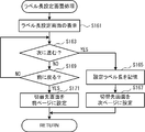
- the display screen of the touch panel 30 is switched to the label length setting screen G6 and displayed (S161).
- the label length setting screen G6 includes an operation area in which the user can freely set the label length (see FIG. 5).
- an operation for instructing to proceed to the next is performed on the label length setting screen G6 (for example, pressing of the enter key displayed on the screen or page turning operation for sliding the finger leftward on the screen) (S163). : YES)
- the label length (set label length) set on the label length setting screen G6 is stored in the RAM 23 (S165).
- the next page of the label length setting screen G6 is set in the RAM 23 as a switching destination screen (S167).
- the switching destination screen is updated to not set.
- an operation for instructing to return to the previous screen on the label length setting screen G6 for example, pressing of the icon “Cancel” displayed on the screen or a page returning operation of sliding the finger to the right on the screen.
- S163: NO, S169: YES the previous page of the label length setting screen G6 is set in the RAM 23 as a switching destination screen (S171).
- the switching destination screen is updated to the label length setting screen G6.
- step S163 If there is no operation that causes page switching (S163: NO, S169: NO), the process returns to step S163, and the user's input operation is awaited. After execution of step S167 or step S171, the process returns to the print target setting process (FIG. 6).
- step S167 or step S171 the display screen of the touch panel 30 is switched from the label length setting screen G6 to the switching destination screen set in step S167 or step S171.
- the switching destination screen is updated to unset in step S167, the display screen of the touch panel 30 is switched to the final screen G7 described later (S11: NO, S15).
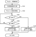
- the print image is displayed. It is generated (S181).
- the display screen of the touch panel 30 is switched to the preview screen including the print image generated in step S181 and displayed (S183).
- a print image representing the set character in the set decoration mode is generated and displayed (see FIGS. 3 to 5).
- an operation for instructing to return to the previous screen on the currently displayed preview screen for example, pressing of the icon “Cancel” displayed on the screen or a page returning operation for sliding the finger to the right on the screen
- the previous page of the currently displayed preview screen is set in the RAM 23 as a switching destination screen (S191).
- the display order of each preview screen indicated by the screen group information is other than the top.
- step S185 If there is no operation that causes page switching (S185: NO, S189: NO), the process returns to step S185, and the user's input operation is awaited. After execution of step S187 or step S191, the process returns to the print target setting process (FIG. 6).
- step S187 or step S191 the display screen of the touch panel 30 is switched from the currently displayed preview screen to the switching destination screen set in step S187 or step S191.
- the display screen of the touch panel 30 is switched to and displayed on the final screen G7 described later (S11: NO, S15).
- step S13 the process returns to step S9 to read out the latest switching destination image.
- the above-described screen switching process is executed (S13), and the display is switched to the next page or the previous page set as the switching destination screen.
- the final screen G7 is displayed on the touch panel 30 (S15).
- the final screen G7 is a key image (icon “Print” shown in FIG. 5) for instructing the printing execution of the print target data (that is, the character stored in the RAM 23 and its decoration mode), and the storage of the print target data.
- a key image indicating the icon “Save File” shown in FIG. 5).
- the print target data is to be printed (S17: YES), and the print command generated based on the print target data is printed via the cable 2. It is transmitted to the device 10 (S19).
- the printing application has a known printer driver function, and the print command is generated by the printing application.
- the icon “Save File” is selected on the final screen G7, it is determined that the print target data is stored (S17: NO, S21: YES), and the print target data is stored in the HDD 24 (new registration or overwrite update). (S23).
- a plurality of screens including a setting screen and a preview screen are displayed on the touch panel 30 based on the screen group information. It is displayed by switching sequentially.
- an input key image is also displayed on the touch panel 30.
- the preview screen is switched and displayed on the touch panel 30. That is, when the user inputs necessary information on the setting screen, a print image based on the input information can be confirmed on the preview screen displayed next.
- a plurality of screens G1 to G7 are sequentially switched and displayed as illustrated in FIGS.
- the user inputs the various information necessary for each of the screens G1 to G7 in sequence, and by referring to the preview screens PV1 to PV4 that are appropriately displayed in the process, the character to be printed and its decoration mode can be accurately and easily determined. Can be set.
- the user can freely set the character and its decoration mode (decoration frame, decoration image, label length, etc.) on the setting screen (character input screen G3, frame selection screen G4, image selection screen G5, label length setting screen G6, etc.). Can be set. Moreover, on these setting screens, a key image for the user to set various information is provided on the touch panel 30. Therefore, even on a portable terminal that does not have physical operation keys, the user can set the character to be printed and its decoration mode accurately and easily.
- the setting screen character input screen G3, frame selection screen G4, image selection screen G5, label length setting screen G6, etc.
- the displayable area of the touch panel 30 is small.
- a key image for information input is displayed on the touch panel 30, an area for displaying various information on the touch panel 30 is further narrowed.
- a computer terminal for example, a smartphone
- a character set by the user and its decoration mode and a preview screen based on the set content are simultaneously displayed in a size that can be recognized by the user. It is difficult to do.
- the screen display is performed according to the procedure determined by the screen group information, and the user can sequentially input necessary information in an interactive manner, and next to the setting screen.
- a preview screen is automatically displayed as appropriate. More specifically, based on the screen group information stored in the HDD 24, a plurality of setting screens are sequentially switched and displayed, and at least one preview is performed before all of the plurality of setting screens are displayed. A screen is displayed.
- the CPU 21 changes the screen group information stored in the HDD 24 according to the designated content.
- the display target screen and its display order are specified so that the user does not set the decorative frame and the decorative image (in other words, sets only the label length) and sets the label length before the character.
- the screen group information stored in the HDD 24 is changed to “G6 ⁇ PV4 ⁇ G3 ⁇ PV1”.
- the CPU 21 changes the screen group information stored in the HDD 24 so that the preview screen is displayed next to the designated setting screen. For example, assume that the user designates only the label length setting screen G6 as the display target of the preview screen. In this case, the screen group information stored in the HDD 24 is changed to “G3 ⁇ G4 ⁇ G5 ⁇ G6 ⁇ PV4”. Thereby, the freedom degree and efficiency at the time of a user setting a character and its decoration aspect can be improved.
- the mobile terminal 20 corresponds to the “image processing apparatus” of the present invention.
- the medium storing the printing application corresponds to the “computer-readable medium storing the image processing program” of the present invention.
- the HDD 24 corresponds to the “screen group storage unit” of the present invention.
- the CPU 21 that executes steps S103, S109, S123, S129, S143, S149, S163, S169, S185, and S189 corresponds to the “switching determination unit” of the present invention.
- the CPU 21 that executes steps S9 to S13 corresponds to the “display control means” of the present invention.
- the CPU 21 that executes step S19 corresponds to the “command transmission unit” of the present invention.
- Steps S103, S109, S123, S129, S143, S149, S163, S169, S185, and S189 correspond to the “switch determination step” of the present invention.
- Steps S9 to S13 correspond to the “display control step” of the present invention.
- the present invention is not limited to the above embodiment, and various modifications are possible.
- the display screen is switched according to a user operation on the touch panel 30, but the display screen of the touch panel 30 may be switched when other conditions are satisfied.
- step S13 For example, in the screen switching process in step S13 (see FIG. 8), after the display screen is switched on the touch panel 30, the latest operation (that is, the last user operation on the display screen) is detected by the touch panel 30. When the elapsed time exceeds a predetermined time (for example, 10 seconds), the display screen may be switched.
- a predetermined time for example, 10 seconds
- steps S103, S123, S143, S163, and S185 it may be determined that the process proceeds to the next when a predetermined time has elapsed from the last user operation on the display screen on the touch panel 30.
- a predetermined time has elapsed since the last user operation on the display screen
- the display screen may be switched when the change in the rotation angle detected by the acceleration sensor 27 exceeds a predetermined angle (for example, 90 degrees). More specifically, in steps S103, S123, S143, S163, and S185, if 90 degree clockwise rotation is detected by the acceleration sensor 27, it may be determined to proceed next.
- a predetermined angle for example, 90 degrees
- the screen can be advanced only by rotating the mobile terminal 20 to the right. It can be done quickly.
- steps S109, S129, S149, S169, and S189 it may be determined to return to the previous position when a 90-degree left rotation is detected by the acceleration sensor 27. Thereby, the user can return the screen only by rotating the mobile terminal 20 counterclockwise.
- the preview screen is displayed on the touch panel 30 in such a manner that the longitudinal direction and the short direction of the rectangular display area of the touch panel 30 match the longitudinal direction and the short direction of the printing image, respectively.
- a portrait setting screen (a character input screen G3 and a frame selection screen G4 in FIG. 14) is displayed.
- the touch panel 30 is in a horizontally rotated state, it is preferable to display a horizontally long preview screen (preview screens PV1 and PV2 in FIG. 14).
- the acceleration sensor 27 corresponds to the “angle detection means” of the present invention.
- the printing apparatus 10 and the mobile terminal 20 are connected by wire with the cable 2, but the printing apparatus 10 and the mobile terminal 20 may be connected wirelessly. It goes without saying that the print target setting process (FIG. 6) can be executed independently even when the portable terminal 20 is not connected to the printing apparatus 10 (except for step S19).
Landscapes
- Engineering & Computer Science (AREA)
- Theoretical Computer Science (AREA)
- General Engineering & Computer Science (AREA)
- Human Computer Interaction (AREA)
- Physics & Mathematics (AREA)
- General Physics & Mathematics (AREA)
- Quality & Reliability (AREA)
- Computer Networks & Wireless Communication (AREA)
- User Interface Of Digital Computer (AREA)
- Facsimiles In General (AREA)
- Accessory Devices And Overall Control Thereof (AREA)
Abstract
携帯端末(20)では、画面の切替タイミングであると判断されると、設定用画面およびプレビュー画面を含む複数の画面が、HDDに記憶されている画面群情報に基づいて、タッチパネル(30)に順次切り替えて表示される。設定用画面が表示される際には、タッチパネル(30)に入力用のキー画像が併せて表示される。設定用画面の表示中に切替タイミングであると判断された場合、タッチパネル(30)にプレビュー画面が切り替えて表示される。
Description
本発明は、ユーザに対話形式で入力操作を行わせるユーザインターフェース機能を備えた画像処理装置、およびこれに用いられる画像処理プログラムを記憶したコンピュータ読取り可能な媒体に関する。
従来、ユーザに対話形式で入力操作を行わせるユーザインターフェース機能を備えた画像処理装置が知られている。このような画像処理装置として、ユーザの入力操作に応じて画像編集を実行する印刷装置が知られている。このような印刷装置は、ユーザによって編集された画像を印刷実行前に表示する、いわゆるプレビュー表示機能を備えることがある(例えば、特許文献1参照)。特許文献1に開示の印刷装置では、オリジナル画像および印刷設定情報が、表示装置に表示される。オリジナル画像の表示後、操作部で所定回数の操作が検出されると、印刷設定情報に基づいて画像調整処理が施されたオリジナル画像(表示用印刷画像)が、表示装置に表示される。
特許文献1に開示の印刷装置では、編集後の画像をプレビュー表示したい場合や、編集前の画像を再び表示したい場合には、ユーザはその都度、所定の画面切替操作を行う必要があった。その後、ユーザがさらなる画像編集を行う場合には、所定の画面切替操作を行うことで、編集目的に応じた画面を表示させる必要があった。
本発明の目的は、画像の編集開始から印刷実行までの操作負担を抑制し、且つ、編集中の画像を適宜確認することができる画像処理装置、およびこれに用いられる画像処理プログラムを記憶したコンピュータ読取り可能な媒体を提供することである。
本発明の第一態様に係る画像処理装置は、ユーザが対話形式で入力操作する対話形式画面を含む複数の画面を切替え表示可能であって、少なくとも表示中の前記対話形式画面に対する操作を検出するタッチパネルと、前記タッチパネルに順次表示される前記複数の画面およびその表示順序を定義する画面群情報を記憶する画面群記憶手段と、所定の条件が満たされた場合に、前記画面の切替タイミングであると判断する切替判断手段と、前記切替判断手段によって前記切替タイミングであると判断されるごとに、前記画面群記憶手段に記憶されている前記画面群情報に基づいて、前記複数の画面を前記タッチパネルに切り替えて表示する表示制御手段とを備え、前記画面群情報によって定義される前記複数の画面は、ユーザにキャラクタおよび装飾態様の何れかを設定させるための前記対話形式画面である設定用画面と、前記設定用画面で設定された前記キャラクタおよび前記装飾態様に基づく印刷用画像を示す前記対話形式画面であるプレビュー画面とを含み、前記表示制御手段は、前記タッチパネルに前記設定用画面を表示する場合、前記設定用画面へ入力するためのキー画像を併せて表示し、前記設定用画面の表示中に前記切替判断手段によって前記切替タイミングであると判断された場合、前記タッチパネルに前記プレビュー画面を切り替えて表示する。
上記第一態様によれば、画面の切替タイミングであると判断されると、設定用画面およびプレビュー画面を含む複数の画面が、画面群情報に基づいてタッチパネルに順次切り替えて表示される。設定用画面が表示される際には、タッチパネルに入力用のキー画像が併せて表示される。設定用画面の表示中に切替タイミングであると判断された場合、タッチパネルにプレビュー画面が切り替えて表示される。したがって、ユーザが設定用画面に必要な情報を入力すると、その入力した情報に基づく印刷用画像を、次に表示されるプレビュー画面で確認できるため、印刷対象のキャラクタおよびその装飾態様の少なくとも一方を正確且つ容易に設定することができる。
前記画面群情報によって定義される前記複数の画面は、複数の前記設定用画面を含み、前記表示制御手段は、前記画面群記憶手段に記憶された前記画面群情報に基づいて、前記複数の設定用画面を順次切り替えて表示し、且つ、前記複数の設定用画面を全て表示するまでの間に少なくとも1回は前記プレビュー画面を表示してもよい。この場合、複数の設定用画面を全て表示するまでの間に少なくとも1回は表示されるプレビュー画面によって、ユーザは現在の印刷用画像を確認することができるため、設定用画面とプレビュー画面とを何度も切り替える操作を行う必要がない。
前記画面群記憶手段に記憶されている前記画面群情報は、ユーザによって指定された前記複数の画面およびその表示順序に応じて変更されてもよい。この場合、ユーザがキャラクタおよびその装飾態様を設定する際の自由度および効率性を高めることができる。
前記画面群記憶手段に記憶されている前記画面群情報は、ユーザが前記プレビュー画面の表示対象とする前記設定用画面を指定した場合、指定された前記設定用画面に次いで前記プレビュー画面が表示されるように変更されてもよい。この場合、ユーザがキャラクタおよびその装飾態様を設定する際の自由度および効率性を高めることができる。
前記切替判断手段は、前記表示制御手段によって前記画面が切替表示された後、前記タッチパネルによって最新の操作が検出された時点からの経過時間が所定時間を超えた場合に、前記画面の切替タイミングであると判断してもよい。この場合、キャラクタおよびその装飾態様の設定作業をより迅速にできる。
前記画像処理装置の定常状態からの回転角度を検出する角度検出手段を備え、前記切替判断手段は、前記角度検出手段によって検出される回転角度の変化が所定角度を超えた場合に、前記画面の切替タイミングであると判断し、前記表示制御手段は、前記切替判断手段によって前記切替タイミングであると判断された場合、前記角度検出手段によって検出される現在の回転角度に応じて、次の前記画面として前記設定用画面および前記プレビュー画面のいずれかに切り替えて表示してもよい。この場合、ユーザは画像処理装置を回転させるだけで画面を切り替えることができる。
前記タッチパネルは、矩形状の表示領域を有し、前記プレビュー画面は、長尺状の媒体に印刷された前記印刷用画像を例示し、前記表示制御手段は、前記矩形状の表示領域の長手方向および短手方向がそれぞれ前記印刷用画像の長手方向および短手方向と一致する態様で、前記タッチパネルに前記プレビュー画面を表示してもよい。この場合、タッチパネルの向きに応じて最適な画面を表示することで、画像処理装置の操作性および表示画面の視認性を向上することができる。
前記画像処理装置は、印刷装置に接続される携帯端末であって、ユーザに前記印刷装置への印刷実行を指示させるための前記対話形式画面である印刷指示画面が前記タッチパネルに表示され、且つ前記印刷指示画面から印刷実行が指示された場合、前記印刷用画像を印刷させるコマンドを前記印刷装置に送信するコマンド送信手段を備えてもよい。この場合、画像処理装置で編集された印刷用画像を、印刷装置に印刷させることができる。
本発明の第二態様に係る画像処理プログラムは、ユーザが対話形式で入力操作する対話形式画面を含む複数の画面を切替え表示可能であって、少なくとも表示中の前記対話形式画面に対する操作を検出するタッチパネルと、前記タッチパネルに順次表示される前記複数の画面およびその表示順序を定義する画面群情報を記憶する画面群記憶手段とを備えた画像処理装置のコンピュータに以下のステップを実行させる指示を含む画像処理プログラムを記憶したコンピュータ読取り可能な媒体であって、所定の条件が満たされた場合に、前記画面の切替タイミングであると判断する切替判断ステップと、前記切替判断ステップによって前記切替タイミングであると判断されるごとに、前記画面群記憶手段に記憶されている前記画面群情報に基づいて、前記複数の画面を前記タッチパネルに切り替えて表示する表示制御ステップとを実行させ、前記画面群情報によって定義される前記複数の画面は、ユーザにキャラクタおよび装飾態様の何れかを設定させるための前記対話形式画面である設定用画面と、前記設定用画面で設定された前記キャラクタおよび前記装飾態様に基づく印刷用画像を示す前記対話形式画面であるプレビュー画面とを含み、前記表示制御ステップは、前記タッチパネルに前記設定用画面を表示する場合、前記設定用画面へ入力するためのキー画像を併せて表示し、前記設定用画面の表示中に前記切替判断ステップによって前記切替タイミングであると判断された場合、前記タッチパネルに前記プレビュー画面を切り替えて表示する。
上記第二態様によれば、画面の切替タイミングであると判断されると、設定用画面およびプレビュー画面を含む複数の画面が、画面群情報に基づいてタッチパネルに順次切り替えて表示される。設定用画面が表示される際には、タッチパネルに入力用のキー画像が併せて表示される。設定用画面の表示中に切替タイミングであると判断された場合、タッチパネルにプレビュー画面が切り替えて表示される。したがって、ユーザが設定用画面に必要な情報を入力すると、その入力した情報に基づく印刷用画像を、次に表示されるプレビュー画面で確認できるため、印刷対象のキャラクタおよびその装飾態様の少なくとも一方を正確且つ容易に設定することができる。
以下、本発明の一実施形態について、図面を参照して説明する。これらの図面は、本発明が採用しうる技術的特徴を説明するために用いられるものである。記載されている装置の構成、各種処理のフローチャート等は、それのみに限定する趣旨ではなく、単なる説明例である。
図1を参照して、印刷システム1の概要について説明する。印刷システム1は、有線または無線によって接続された印刷装置10および携帯端末20を備えている。本実施形態では、印刷装置10および携帯端末20がケーブル2によって接続されている。印刷装置10は、長尺状の印刷媒体であるテープにキャラクタ(文字、記号、図形など)を印刷するためのラベルプリンタである。携帯端末20は、ユーザが印刷対象のキャラクタおよびその装飾態様を設定するために用いる小型のコンピュータ端末(一例として、スマートフォン)である。
携帯端末20では、ユーザがキャラクタおよび装飾態様を設定すると、その設定内容を示す印刷対象データが生成される。携帯端末20で生成された印刷対象データは、ケーブル2を介して印刷装置10に対して送信される。印刷装置10では、携帯端末20から受信した印刷対象データに基づいて、テープへの印刷処理が行われる。従ってユーザは、携帯端末20を操作することで、印刷装置10でテープに印刷することができる。
図2を参照して、印刷システム1の電気的構成を説明する。印刷装置10は、印刷装置10の制御全体を司るCPU11を備えている。CPU11は、SRAM12、FLASH ROM13、EEPROM14、ローラ15、ヘッド16、操作キー17、ディスプレイ18、および外部機器インタフェース(外部機器I/F)19と電気的に接続している。
SRAM12には、タイマやカウンタ、一時的なデータが記憶される。FLASH ROM13には、CPU11の制御プログラムやBIOS、OS等が記憶される。EEPROM14には、パラメータや初期設定情報が記憶される。ローラ15は、印刷装置10に装着されているテープカセット(図示外)に収納されているテープを搬送する。ヘッド16は、ローラ15によって搬送されるテープに印刷を行う。外部機器I/F19は、ケーブル2を介して携帯端末20と通信を行うためのコントローラである。
携帯端末20は、CPU21、ROM22、RAM23、HDD24、外部機器I/F25、通信部26、加速度センサ27、およびタッチパネル30と電気的に接続している。ROM22には、ブートプログラムやBIOS等が記憶される。RAM23には、タイマやカウンタ、一時的なデータが記憶される。HDD24には、各種のアプリケーションプログラムやOSが記憶される。後述する印刷対象設定処理(図6参照)を実行するためのアプリケーションプログラム(以下、印刷用アプリケーション)や、印刷用アプリケーションによって使用される後述の画面群情報も、HDD24に記憶されている。なお、携帯端末20は、CD-ROM等のコンピュータ読取り可能な媒体に記憶された印刷用アプリケーションを、HDD24にインストールすればよい。
外部機器I/F25は、ケーブル2を介して印刷装置10と通信を行うためのコントローラである。通信部26は、図示外の公衆回線網を介して他の電子機器と通信を行うためのコントローラである。加速度センサ27は、携帯端末20の加速度を検出することで、携帯端末20の定常状態からの回転角度(つまり、携帯端末20の傾き)を特定する。
携帯端末20は、正面視で矩形状の本体部29(図1参照)を備える。本体部29の正面側には、外部物体の接触を検知可能な表示体であるタッチパネル30が設けられている。タッチパネル30は、本体部29の形状に対応して矩形状の表示領域を有する。タッチパネル30は、画像を表示する表示パネル31上に、外部物体の接触を検知する略透明な感圧シート32が積層されている。CPU21は、感圧シート32で特定された外部物体の接触位置に基づいて、ユーザの入力操作を判別可能である。
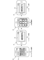
図3~図5を参照して、携帯端末20の操作態様および画面遷移の一例を説明する。携帯端末20は、ユーザに対話形式で入力操作を行わせるユーザインターフェース機能を備えている。ユーザによって印刷用アプリケーションが起動されると、初期画面G1がタッチパネル30に表示される。初期画面G1は、ユーザに印刷対象データの新規作成または更新のいずれを実行するかを選択させる画面である。
初期画面G1で印刷対象データの更新(後述するアイコン「Open File」)が選択されると、ファイル選択画面G2がタッチパネル30に表示される。ファイル選択画面G2は、ユーザに既存の印刷対象データを選択させる画面である。初期画面G1で印刷対象データの新規作成(後述するアイコン「New File」)が選択され、またはファイル選択画面G2で印刷対象データが選択されると、ユーザが対話形式で入力操作する対話形式画面を含む複数の画面が、HDD24に記憶されている画面群情報に基づいて、タッチパネル30に切替え表示される。
画面群情報は、印刷用アプリケーションの実行時に、タッチパネル30に表示する特定の対話形式画面(以下、表示対象画面という。)、およびその表示順序を定義する。表示対象画面は、ユーザにキャラクタおよびその装飾態様を設定させるための設定用画面と、設定用画面で設定された内容に基づく印刷用画像を示すプレビュー画面とを含む。本実施形態の画面群情報は、各プレビュー画面がいずれの設定用画面に次いで表示されるかの表示順序を示す。
本実施形態の設定用画面は、キャラクタ入力画面G3、枠選択画面G4、画像選択画面G5、ラベル長設定画面G6を含む。キャラクタ入力画面G3は、ユーザに印刷対象のキャラクタを設定させるための画面である。枠選択画面G4、画像選択画面G5、ラベル長設定画面G6は、ユーザにキャラクタの装飾態様を設定させるための画面である。具体的には、枠選択画面G4では、キャラクタの周囲を装飾する「装飾枠」を設定できる。画像選択画面G5では、キャラクタに挿入される「装飾画像」を設定できる。ラベル長設定画面G6では、キャラクタが印刷されるテープの「ラベル長」を設定できる。
キャラクタ入力画面G3、枠選択画面G4、画像選択画面G5、ラベル長設定画面G6にそれぞれ対応して、印刷用画像を長尺状の媒体(テープ)に印刷した状態を例示するプレビュー画面PV1~PV4が設けられている。詳細には、プレビュー画面PV1は、キャラクタ入力画面G3で設定されたキャラクタに基づく印刷用画像を表示する。プレビュー画面PV2は、枠選択画面G4で設定された装飾枠に基づく印刷用画像を表示する。プレビュー画面PV3は、画像選択画面G5で設定された装飾画像に基づく印刷用画像を表示する。プレビュー画面PV4は、ラベル長設定画面G6で設定されたラベル長に基づく印刷用画像を表示する。
本実施形態のプレビュー画面PV1~PV4は、それぞれ、各プレビュー画面の表示前に設定された全ての内容を反映した印刷用画像を示す。具体的に、図5に例示するプレビュー画面PV4は、キャラクタ入力画面G3で設定されたキャラクタを、枠選択画面G4で設定された装飾枠と、画像選択画面G5で設定された装飾画像と、ラベル長設定画面G6で設定されたラベル長とで表した印刷用画像を表示している。
画面群情報が示す全ての表示対象画面が表示されたのち、最終画面G7がタッチパネル30に表示される。最終画面G7は、ユーザに印刷対象データの印刷および保存のいずれを実行するかを選択させる画面である。
なお、HDD24に記憶されている画面群情報は、ユーザが指定した表示対象画面およびその表示順序に応じて変更される。つまり、印刷用アプリケーションの起動時に表示される表示対象画面およびその表示順序を、ユーザは自由に設定することができる。画面群情報が変更されていない初期状態では、HDD24にはデフォルトの画面群情報が記憶される。デフォルトの画面群情報では、表示対象画面およびその表示順序として、「G3→PV1→G4→PV2→G5→PV3→G6→PV4」が定義されている。したがって、HDD24にデフォルトの画面群情報が記憶された状態で印刷用アプリケーションが起動されると、図3~図5に例示するように複数の画面が順次切り替え表示される。
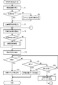
図6~図13を参照して、携帯端末20で実行される印刷対象設定処理について説明する。印刷対象設定処理(図6)は、携帯端末20で印刷用アプリケーションが起動されると、CPU21によって実行される。
図6に示すように、印刷対象設定処理では、まず初期画面G1がタッチパネル30に表示される(S1)。初期画面G1は、印刷対象データの新規作成を指示するためのキー画像(図3に示すアイコン「New File」)と、既存の印刷対象データの更新を指示するためのキー画像(図3に示すアイコン「Open File」)とを含む。初期画面G1でアイコン「Open File」が選択された場合、既存の印刷対象データの更新であると判断され(S3:NO)、以下のファイル選択画面処理が実行される(S5)。
図7に示すように、ファイル選択画面処理では、タッチパネル30の表示画面が、初期画面G1からファイル選択画面G2に切り替えて表示される(S51)。ファイル選択画面G2は、既存の印刷対象データを指定するための入力領域を含み、ユーザはその入力領域に一覧表示される印刷対象データのいずれかを自由に指定できる。なお、入力領域に一覧表示される印刷対象データは、ファイル選択画面G2に含まれるキー画像(図3に示すアイコン「Next Page・・」)を押下すると切り替えることができる。ファイル選択画面G2で印刷対象データが指定された場合(S53:YES)、その指定された印刷対象データがRAM23に読み出される(S55)。ステップS55の実行後、処理は印刷対象設定処理(図6)に戻る。なお、印刷対象データが指定されない場合(S53:NO)、処理はステップS53に戻り、ユーザの入力操作が待ち受けられる。
図6に戻る。初期画面G1でアイコン「New File」が選択された場合、印刷対象データの新規作成であると判断される(S3:YES)。この場合、RAM23に設定された新規の印刷対象データを対象として、ステップS7以降の処理が実行される。一方、ステップS5の実行後は、RAM23に読み出された既存の印刷対象データを対象として、ステップS7以降の処理が実行される。ステップS7では、HDD24に記憶されている画面群情報がRAM23に読み出される。このとき、画面群情報が示す先頭ページが、RAM23に切替先画面(現在表示中の画面に切り替えて表示する画面)として設定される。
ステップS7の実行後、RAM23に対して切替先画面の読み出しが実行され(S9)、切替先画面ありか否かが判断される(S11)。RAM23から切替先画面が読み出された場合、切替先画面ありと判断されて(S11:YES)、以下の画面切替処理が実行される(S13)。
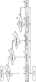
図8に示すように、画面切替処理では、まずステップS9で読み出された切替先画面が、キャラクタ入力画面G3であるか否かが判断される(S71)。切替先画面がキャラクタ入力画面G3である場合(S71:YES)、後述のキャラクタ入力画面処理が実行される(S73)。切替先画面がキャラクタ入力画面G3でない場合(S71:NO)、切替先画面が枠選択画面G4であるか否かが判断される(S75)。切替先画面が枠選択画面G4である場合(S75:YES)、後述の枠選択画面処理が実行される(S77)。切替先画面が枠選択画面G4でない場合(S75:NO)、切替先画面が画像選択画面G5であるか否かが判断される(S79)。切替先画面が画像選択画面G5である場合(S79:YES)、後述の画像選択画面処理が実行される(S81)。
切替先画面が画像選択画面G5でない場合(S79:NO)、切替先画面がラベル長設定画面G6であるか否かが判断される(S83)。切替先画面がラベル長設定画面G6である場合(S83:YES)、後述のラベル長設定画面処理が実行される(S85)。切替先画面がラベル長設定画面G6でない場合(S83:NO)、切替先画面はプレビュー画面PV1~PV4のいずれかであるため、後述のプレビュー画面処理が実行される(S87)。ステップS73、S77、S81、S85、S87のいずれかの実行後、処理は印刷対象設定処理(図6)に戻る。
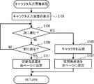
図9に示すように、キャラクタ入力画面処理では、タッチパネル30の表示画面が、キャラクタ入力画面G3に切り替えて表示される(S101)。キャラクタ入力画面G3は、キャラクタを入力するための操作キーを示すキー画像(図3に示すキーボードを模した画像)や、入力されたキャラクタの表示領域などを含む。キャラクタ入力画面G3で次に進むことを指示する操作(例えば、画面上に表示された決定キーの押下や、画面上で指を左方向へスライドさせるページ送り操作など)が行われると(S103:YES)、キャラクタ入力画面G3に入力されたキャラクタがRAM23に記憶される(S105)。
その後、HDD24に記憶されている画面群情報に基づいて、キャラクタ入力画面G3よりも表示順序が一つ後の画面(すなわち、次ページ)が、RAM23に切替先画面として設定される(S107)。ただし、画面群情報が示すキャラクタ入力画面G3の表示順序が末尾であれば、切替先画面は未設定に更新される。
一方、キャラクタ入力画面G3で前に戻ることを指示する操作(例えば、画面上に表示されたアイコン「Cancel」の押下や、画面上で指を右方向へスライドさせるページ戻し操作など)が行われると(S103:NO、S109:YES)、キャラクタ入力画面G3よりも表示順序が一つ前の画面(すなわち、前ページ)が、RAM23に切替先画面として設定される(S111)。ただし、画面群情報が示すキャラクタ入力画面G3の表示順序が先頭であれば、切替先画面はキャラクタ入力画面G3に更新される。
ページの切り替えを発生させる操作がない場合(S103:NO、S109:NO)、処理はステップS103に戻り、ユーザの入力操作が待ち受けられる。ステップS107またはステップS111の実行後、処理は印刷対象設定処理(図6)に戻る。なお、次回の画面切替処理(図8)では、タッチパネル30の表示画面が、キャラクタ入力画面G3からステップS107またはステップS111で設定された切替先画面に切り替えて表示される。ただし、ステップS107で切替先画面が未設定に更新された場合は、タッチパネル30の表示画面が後述の最終画面G7に切り替えて表示される(S11:NO、S15)。
図10に示すように、枠選択画面処理では、タッチパネル30の表示画面が、枠選択画面G4に切り替えて表示される(S121)。枠選択画面G4は、複数の装飾枠がリスト状に表示されるとともに、ユーザがいずれかの装飾枠を自由に選択可能な操作領域を含む(図4参照)。枠選択画面G4で次に進むことを指示する操作(例えば、画面上に表示された枠の選択操作や、画面上で指を左方向へスライドさせるページ送り操作など)が行われると(S123:YES)、枠選択画面G4で選択された装飾枠(選択枠)がRAM23に記憶される(S125)。
その後、HDD24に記憶されている画面群情報に基づいて、枠選択画面G4の次ページが、RAM23に切替先画面として設定される(S127)。ただし、画面群情報が示す枠選択画面G4の表示順序が末尾であれば、切替先画面は未設定に更新される。一方、枠選択画面G4で前に戻ることを指示する操作(例えば、画面上に表示されたアイコン「Cancel」の押下や、画面上で指を右方向へスライドさせるページ戻し操作など)が行われると(S123:NO、S129:YES)、枠選択画面G4の前ページが、RAM23に切替先画面として設定される(S131)。ただし、画面群情報が示す枠選択画面G4の表示順序が先頭であれば、切替先画面は枠選択画面G4に更新される。
ページの切り替えを発生させる操作がない場合(S123:NO、S129:NO)、処理はステップS123に戻り、ユーザの入力操作が待ち受けられる。ステップS127またはステップS131の実行後、処理は印刷対象設定処理(図6)に戻る。なお、次回の画面切替処理(図8)では、タッチパネル30の表示画面が、枠選択画面G4からステップS127またはステップS131で設定された切替先画面に切り替えて表示される。ただし、ステップS127で切替先画面が未設定に更新された場合は、タッチパネル30の表示画面が後述の最終画面G7に切り替えて表示される(S11:NO、S15)。
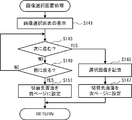
図11に示すように、画像選択画面処理では、タッチパネル30の表示画面が、画像選択画面G5に切り替えて表示される(S141)。画像選択画面G5は、複数の装飾画像がリスト状に表示されるとともに、ユーザがいずれかの装飾画像を自由に選択可能な操作領域を含む(図4参照)。画像選択画面G5で次に進むことを指示する操作(例えば、画面上に表示された画像の選択操作や、画面上で指を左方向へスライドさせるページ送り操作など)が行われると(S143:YES)、画像選択画面G5で選択された装飾画像(選択画像)がRAM23に記憶される(S145)。
その後、HDD24に記憶されている画面群情報に基づいて、画像選択画面G5の次ページが、RAM23に切替先画面として設定される(S147)。ただし、画面群情報が示す画像選択画面G5の表示順序が末尾であれば、切替先画面は未設定に更新される。一方、画像選択画面G5で前に戻ることを指示する操作(例えば、画面上に表示されたアイコン「Cancel」の押下や、画面上で指を右方向へスライドさせるページ戻し操作など)が行われると(S143:NO、S149:YES)、画像選択画面G5の前ページが、RAM23に切替先画面として設定される(S151)。ただし、画面群情報が示す画像選択画面G5の表示順序が先頭であれば、切替先画面は画像選択画面G5に更新される。
ページの切り替えを発生させる操作がない場合(S143:NO、S149:NO)、処理はステップS143に戻り、ユーザの入力操作が待ち受けられる。ステップS147またはステップS151の実行後、処理は印刷対象設定処理(図6)に戻る。なお、次回の画面切替処理(図8)では、タッチパネル30の表示画面が、画像選択画面G5からステップS147またはステップS151で設定された切替先画面に切り替えて表示される。ただし、ステップS147で切替先画面が未設定に更新された場合は、タッチパネル30の表示画面が後述の最終画面G7に切り替えて表示される(S11:NO、S15)。
図12に示すように、ラベル長設定画面処理では、タッチパネル30の表示画面が、ラベル長設定画面G6に切り替えて表示される(S161)。ラベル長設定画面G6は、ユーザがラベル長を自由に設定可能な操作領域を含む(図5参照)。ラベル長設定画面G6で次に進むことを指示する操作(例えば、画面上に表示された決定キーの押下や、画面上で指を左方向へスライドさせるページ送り操作など)が行われると(S163:YES)、ラベル長設定画面G6で設定されたラベル長(設定ラベル長)がRAM23に記憶される(S165)。
その後、HDD24に記憶されている画面群情報に基づいて、ラベル長設定画面G6の次ページが、RAM23に切替先画面として設定される(S167)。ただし、画面群情報が示すラベル長設定画面G6の表示順序が末尾であれば、切替先画面は未設定に更新される。一方、ラベル長設定画面G6で前に戻ることを指示する操作(例えば、画面上に表示されたアイコン「Cancel」の押下や、画面上で指を右方向へスライドさせるページ戻し操作など)が行われると(S163:NO、S169:YES)、ラベル長設定画面G6の前ページが、RAM23に切替先画面として設定される(S171)。ただし、画面群情報が示すラベル長設定画面G6の表示順序が先頭であれば、切替先画面はラベル長設定画面G6に更新される。
ページの切り替えを発生させる操作がない場合(S163:NO、S169:NO)、処理はステップS163に戻り、ユーザの入力操作が待ち受けられる。ステップS167またはステップS171の実行後、処理は印刷対象設定処理(図6)に戻る。なお、次回の画面切替処理(図8)では、タッチパネル30の表示画面が、ラベル長設定画面G6からステップS167またはステップS171で設定された切替先画面に切り替えて表示される。ただし、ステップS167で切替先画面が未設定に更新された場合は、タッチパネル30の表示画面が後述の最終画面G7に切り替えて表示される(S11:NO、S15)。
図13に示すように、プレビュー画面処理では、まず、現時点までに表示された設定用画面で設定済みの内容(つまり、RAM23に記憶されているキャラクタおよび装飾態様)に基づいて、印刷用画像が生成される(S181)。タッチパネル30の表示画面が、ステップS181で生成された印刷用画像を含むプレビュー画面に切り替えて表示される(S183)。これにより、例えば表示対象のプレビュー画面PV1~PV4に応じて、設定済みのキャラクタを設定済みの装飾態様で表した印刷用画像が生成および表示される(図3~図5参照)。
表示中のプレビュー画面で次に進むことを指示する操作(例えば、画面上に表示された決定キーの押下や、画面上で指を左方向へスライドさせるページ送り操作など)が行われると(S185:YES)、HDD24に記憶されている画面群情報に基づいて、表示中のプレビュー画面の次ページが、RAM23に切替先画面として設定される(S187)。ただし、画面群情報が示す表示中のプレビュー画面の表示順序が末尾であれば、切替先画面は未設定に更新される。
一方、表示中のプレビュー画面で前に戻ることを指示する操作(例えば、画面上に表示されたアイコン「Cancel」の押下や、画面上で指を右方向へスライドさせるページ戻し操作など)が行われると(S185:NO、S189:YES)、表示中のプレビュー画面の前ページが、RAM23に切替先画面として設定される(S191)。なお、本実施形態では、画面群情報が示す各プレビュー画面の表示順序は先頭以外である。
ページの切り替えを発生させる操作がない場合(S185:NO、S189:NO)、処理はステップS185に戻り、ユーザの入力操作が待ち受けられる。ステップS187またはステップS191の実行後、処理は印刷対象設定処理(図6)に戻る。なお、次回の画面切替処理(図8)では、タッチパネル30の表示画面が、表示中のプレビュー画面からステップS187またはステップS191で設定された切替先画面に切り替えて表示される。ただし、ステップS187で切替先画面が未設定に更新された場合は、タッチパネル30の表示画面が後述の最終画面G7に切り替えて表示される(S11:NO、S15)。
図6に戻る。ステップS13の実行後、ステップS9に戻って最新の切替先画像の読み出しが実行される。RAM23に最新の切替先画面がある場合(S11:YES)、先述の画面切替処理が実行されて(S13)、切替先画面として設定されている次ページまたは前ページに切替え表示される。一方、RAM23に最新の切替先画面がない場合(S11:NO)、最終画面G7がタッチパネル30に表示される(S15)。最終画面G7は、印刷対象データ(つまり、RAM23に記憶されているキャラクタおよびその装飾態様)の印刷実行を指示するためのキー画像(図5に示すアイコン「Print」)と、印刷対象データの保存を指示するためのキー画像(図5に示すアイコン「Save File」)とを含む。
最終画面G7でアイコン「Print」が選択された場合、印刷対象データの印刷実行であると判断され(S17:YES)、印刷対象データに基づいて生成された印刷コマンドが、ケーブル2を介して印刷装置10に送信される(S19)。本実施形態では、印刷用アプリケーションが公知のプリンタドライバ機能を有しており、上記の印刷コマンドは印刷用アプリケーションによって生成される。最終画面G7でアイコン「Save File」が選択された場合、印刷対象データの保存であると判断され(S17:NO、S21:YES)、印刷対象データがHDD24に保存(新規登録または上書き更新)される(S23)。
一方、最終画面G7で前に戻ることを指示する操作(例えば、画面上に表示されたアイコン「Cancel」の押下や、画面上で指を右方向へスライドさせるページ戻し操作など)が行われると(S21:NO、S25:YES)、最終画面G7の前ページがRAM23に切替先画面として設定され(S27)、処理はステップS9に戻る。これにより、次回の画面切替処理(図8)では、タッチパネル30の表示画面が、最終画面G7からステップS27で設定された切替先画面に切り替えて表示される。なお、ページの切り替えを発生させる操作がない場合(S25:NO)、処理はステップS17に戻り、ユーザの入力操作が待ち受けられる。ステップS19またはステップS23の実行後、印刷対象設定処理(図6)は終了する。
以上の構成及び処理によって、本実施形態の携帯端末20では、画面の切替タイミングであると判断されると、設定用画面およびプレビュー画面を含む複数の画面が、画面群情報に基づいてタッチパネル30に順次切り替えて表示される。設定用画面が表示される際には、タッチパネル30に入力用のキー画像が併せて表示される。設定用画面の表示中に切替タイミングであると判断された場合、タッチパネル30にプレビュー画面が切り替えて表示される。つまり、ユーザが設定用画面に必要な情報を入力すると、その入力した情報に基づく印刷用画像を、次に表示されるプレビュー画面で確認できる。
例えば、HDD24にデフォルトの画面群情報が記憶された状態で印刷用アプリケーションが起動されると、図3~図5に例示するように複数の画面G1~G7が順次切り替え表示される。ユーザは、各画面G1~G7に必要な各種情報を順次入力しつつ、その過程で適宜表示されるプレビュー画面PV1~PV4を参照することで、印刷対象のキャラクタおよびその装飾態様を正確且つ容易に設定することができる。
ユーザは、設定用画面(キャラクタ入力画面G3、枠選択画面G4、画像選択画面G5、ラベル長設定画面G6など)で、キャラクタおよびその装飾態様(装飾枠、装飾画像、ラベル長など)を自由に設定できる。しかも、これらの設定用画面では、ユーザが各種情報を設定するためのキー画像が、タッチパネル30上に提供される。よって、物理的な操作キーを有しない携帯端末でも、ユーザは印刷対象のキャラクタおよびその装飾態様を正確且つ容易に設定することができる。
ところで、携帯端末20のような小型のコンピュータ端末では、タッチパネル30の表示可能領域が小さい。タッチパネル30に情報入力用のキー画像を表示すると、タッチパネル30で各種情報を表示するための領域がさらに狭くなる。その結果、従来のキー画像を表示可能なコンピュータ端末(例えば、スマートフォン)では、ユーザが設定したキャラクタおよびその装飾態様と、その設定内容に基づくプレビュー画面とを、ユーザが認識可能なサイズで同時に表示するのは困難である。
したがって、例えば従来のスマートフォンにおいて、複数の画面に対話形式でキャラクタおよびその装飾態様を順次入力する場合は、ユーザが一の設定用画面で情報入力したのち、プレビュー画面に切り替えて所望の印刷結果を得られるか否かを確認する。プレビュー画面で表示された印刷結果に問題がなければ、プレビュー画面から元の設定用画面に戻り、さらに他の設定用画面に切り替えて情報入力を再開する必要があった。
その点、本実施形態の携帯端末20では、画面群情報によって定められた手順で画面表示が行われて、ユーザが対話形式で必要な情報を順次入力することができ、しかも設定用画面に次いでプレビュー画面が自動的に適宜表示される。より詳細には、HDD24に記憶されている画面群情報に基づいて、複数の設定用画面が順次切り替えて表示され、且つ、複数の設定用画面を全て表示するまでの間に少なくとも1回はプレビュー画面が表示される。
そのため、ユーザがキャラクタおよびその装飾態様を設定する際に、一の設定用画面に次いで表示されるプレビュー画面に問題がなければ、一の設定用画面に戻ることなく他の設定用画面に進むため、設定用画面とプレビュー画面とを何度も切り替える操作を行う必要がない。したがって、小型のコンピュータ端末であっても、ユーザは印刷対象のキャラクタおよびその装飾態様を正確且つ容易に設定することができる。
なお、本実施形態では、ユーザが表示対象画面およびその表示順序を指定すると、CPU21はHDD24に記憶されている画面群情報を指定内容に応じて変更する。例えば、ユーザが装飾枠および装飾画像を設定せず(言い換えると、ラベル長だけを設定し)、且つ、ラベル長をキャラクタよりも先に設定するように、表示対象画面およびその表示順序を指定したとする。この場合、HDD24に記憶されている画面群情報は、「G6→PV4→G3→PV1」に変更される。これにより、ユーザがキャラクタおよびその装飾態様を設定する際の自由度および効率性を高めることができる。
ユーザがプレビュー画面の表示対象とする設定用画面を指定すると、CPU21はHDD24に記憶されている画面群情報を、指定された設定用画面に次いでプレビュー画面が表示されるように変更する。例えば、ユーザがラベル長設定画面G6のみをプレビュー画面の表示対象として指定したとする。この場合、HDD24に記憶されている画面群情報は、「G3→G4→G5→G6→PV4」に変更される。これにより、ユーザがキャラクタおよびその装飾態様を設定する際の自由度および効率性を高めることができる。
上記実施形態において、携帯端末20が、本発明の「画像処理装置」に相当する。印刷用アプリケーションを記憶した媒体が、本発明の「画像処理プログラムを記憶したコンピュータ読取り可能な媒体」に相当する。HDD24が本発明の「画面群記憶手段」に相当する。ステップS103、S109、S123、S129、S143、S149、S163、S169、S185、S189を実行するCPU21が、本発明の「切替判断手段」に相当する。ステップS9~S13を実行するCPU21が、本発明の「表示制御手段」に相当する。ステップS19を実行するCPU21が、本発明の「コマンド送信手段」に相当する。ステップS103、S109、S123、S129、S143、S149、S163、S169、S185、S189が、本発明の「切替判断ステップ」に相当する。ステップS9~S13が、本発明の「表示制御ステップ」に相当する。
本発明は上記実施形態に限定されるものではなく、種々の変更が可能である。上記実施形態では、タッチパネル30に対するユーザ操作に応じて表示画面が切替えられるが、タッチパネル30の表示画面は他の条件が満たされた場合に切替えられてもよい。
例えば、ステップS13の画面切替処理(図8参照)において、タッチパネル30で表示画面が切替えられた後で、タッチパネル30によって最新の操作(つまり、表示画面に対する最後のユーザ操作)が検出された時点からの経過時間が所定時間(例えば、10秒)を超えた場合に、表示画面が切り換えられてもよい。
より具体的には、ステップS103、S123、S143、S163、S185では、タッチパネル30で表示画面に対する最後のユーザ操作からの所定時間が経過した場合に、次に進むと判断されればよい。これにより、表示画面に対する最後のユーザ操作から所定時間が経過した場合には、表示画面に対する情報設定が完了しているものとみなして画面を進めることで、キャラクタおよびその装飾態様の設定作業をより迅速にできる。
ステップS13の画面切替処理(図8参照)において、加速度センサ27によって検出される回転角度の変化が所定角度(例えば、90度)を超えた場合に、表示画面が切り換えられてもよい。より具体的には、ステップS103、S123、S143、S163、S185では、加速度センサ27によって90度の右回転が検出された場合に、次に進むと判断されればよい。
これにより、図14に例示するように、ユーザが表示画面に対する情報設定を完了したのちに携帯端末20を右回転させるだけで画面を進めることができ、ひいてはキャラクタおよびその装飾態様の設定作業をより迅速にできる。逆に、ステップS109、S129、S149、S169、S189では、加速度センサ27によって90度の左回転が検出された場合に、前に戻ると判断されてもよい。これにより、ユーザは携帯端末20を左回転させるだけで画面を戻すことができる。
この変形例では、図14に示すように、タッチパネル30の矩形状の表示領域の長手方向および短手方向がそれぞれ印刷用画像の長手方向および短手方向と一致する態様で、タッチパネル30にプレビュー画面が表示されることが好適である。具体的には、タッチパネル30が縦長となる回転状態にあるときは、縦長の設定用画面(図14では、キャラクタ入力画面G3および枠選択画面G4)が表示されることが好適である。一方、タッチパネル30が横長となる回転状態にあるときは、横長のプレビュー画面(図14では、プレビュー画面PV1、PV2)が表示されることが好適である。これにより、タッチパネル30の向きに応じて最適な画面を表示することで、携帯端末20の操作性および表示画面の視認性を向上することができる。本変形例では、加速度センサ27が本発明の「角度検出手段」に相当する。
なお、上記実施形態に例示した印刷システム1では、印刷装置10および携帯端末20がケーブル2で有線接続されているが、印刷装置10および携帯端末20が無線で接続されてもよい。印刷対象設定処理(図6)は、携帯端末20が印刷装置10に接続されていない状態でも、携帯端末20が単独で実行可能であることは言うまでもない(ただし、ステップS19を除く。)。
Claims (9)
- ユーザが対話形式で入力操作する対話形式画面を含む複数の画面を切替え表示可能であって、少なくとも表示中の前記対話形式画面に対する操作を検出するタッチパネル(30)と、
前記タッチパネルに順次表示される前記複数の画面およびその表示順序を定義する画面群情報を記憶する画面群記憶手段(24)と、
所定の条件が満たされた場合に、前記画面の切替タイミングであると判断する切替判断手段(21)と、
前記切替判断手段によって前記切替タイミングであると判断されるごとに、前記画面群記憶手段に記憶されている前記画面群情報に基づいて、前記複数の画面を前記タッチパネルに切り替えて表示する表示制御手段(21)とを備え、
前記画面群情報によって定義される前記複数の画面は、ユーザにキャラクタおよび装飾態様の何れかを設定させるための前記対話形式画面である設定用画面と、前記設定用画面で設定された前記キャラクタおよび前記装飾態様に基づく印刷用画像を示す前記対話形式画面であるプレビュー画面とを含み、
前記表示制御手段は、前記タッチパネルに前記設定用画面を表示する場合、前記設定用画面へ入力するためのキー画像を併せて表示し、前記設定用画面の表示中に前記切替判断手段によって前記切替タイミングであると判断された場合、前記タッチパネルに前記プレビュー画面を切り替えて表示する画像処理装置(20)。 - 前記画面群情報によって定義される前記複数の画面は、複数の前記設定用画面を含み、
前記表示制御手段は、前記画面群記憶手段に記憶された前記画面群情報に基づいて、前記複数の設定用画面を順次切り替えて表示し、且つ、前記複数の設定用画面を全て表示するまでの間に少なくとも1回は前記プレビュー画面を表示する請求項1に記載の画像処理装置。 - 前記画面群記憶手段に記憶されている前記画面群情報は、ユーザによって指定された前記複数の画面およびその表示順序に応じて変更される請求項2に記載の画像処理装置。
- 前記画面群記憶手段に記憶されている前記画面群情報は、ユーザが前記プレビュー画面の表示対象とする前記設定用画面を指定した場合、指定された前記設定用画面に次いで前記プレビュー画面が表示されるように変更される請求項2または3に記載の画像処理装置。
- 前記切替判断手段は、前記表示制御手段によって前記画面が切替表示された後、前記タッチパネルによって最新の操作が検出された時点からの経過時間が所定時間を超えた場合に、前記画面の切替タイミングであると判断する請求項1から4のいずれかに記載の画像処理装置。
- 前記画像処理装置の定常状態からの回転角度を検出する角度検出手段(27)を備え、
前記切替判断手段は、前記角度検出手段によって検出される回転角度の変化が所定角度を超えた場合に、前記画面の切替タイミングであると判断し、
前記表示制御手段は、前記切替判断手段によって前記切替タイミングであると判断された場合、前記角度検出手段によって検出される現在の回転角度に応じて、次の前記画面として前記設定用画面および前記プレビュー画面のいずれかに切り替えて表示する請求項1から4のいずれかに記載の画像処理装置。 - 前記タッチパネルは、矩形状の表示領域を有し、
前記プレビュー画面は、長尺状の媒体に印刷された前記印刷用画像を例示し、
前記表示制御手段は、前記矩形状の表示領域の長手方向および短手方向がそれぞれ前記印刷用画像の長手方向および短手方向と一致する態様で、前記タッチパネルに前記プレビュー画面を表示する請求項6に記載の画像処理装置。 - 前記画像処理装置は、印刷装置に接続される携帯端末であって、
ユーザに前記印刷装置への印刷実行を指示させるための前記対話形式画面である印刷指示画面が前記タッチパネルに表示され、且つ前記印刷指示画面から印刷実行が指示された場合、前記印刷用画像を印刷させるコマンドを前記印刷装置に送信するコマンド送信手段を備えた請求項1から7のいずれかに記載の画像処理装置。 - ユーザが対話形式で入力操作する対話形式画面を含む複数の画面を切替え表示可能であって、少なくとも表示中の前記対話形式画面に対する操作を検出するタッチパネル(30)と、前記タッチパネルに順次表示される前記複数の画面およびその表示順序を定義する画面群情報を記憶する画面群記憶手段(24)とを備えた画像処理装置(20)のコンピュータ(21)に以下のステップを実行させる指示を含む画像処理プログラムを記憶したコンピュータ読取り可能な媒体であって、
所定の条件が満たされた場合に、前記画面の切替タイミングであると判断する切替判断ステップと、
前記切替判断ステップによって前記切替タイミングであると判断されるごとに、前記画面群記憶手段に記憶されている前記画面群情報に基づいて、前記複数の画面を前記タッチパネルに切り替えて表示する表示制御ステップとを実行させ、
前記画面群情報によって定義される前記複数の画面は、ユーザにキャラクタおよび装飾態様の何れかを設定させるための前記対話形式画面である設定用画面と、前記設定用画面で設定された前記キャラクタおよび前記装飾態様に基づく印刷用画像を示す前記対話形式画面であるプレビュー画面とを含み、
前記表示制御ステップは、前記タッチパネルに前記設定用画面を表示する場合、前記設定用画面へ入力するためのキー画像を併せて表示し、前記設定用画面の表示中に前記切替判断ステップによって前記切替タイミングであると判断された場合、前記タッチパネルに前記プレビュー画面を切り替えて表示する画像処理プログラムを記憶したコンピュータ読取り可能な媒体。
Priority Applications (1)
| Application Number | Priority Date | Filing Date | Title |
|---|---|---|---|
| US14/097,297 US9323430B2 (en) | 2011-06-08 | 2013-12-05 | Image processing device and non-transitory computer-readable medium storing image processing program |
Applications Claiming Priority (2)
| Application Number | Priority Date | Filing Date | Title |
|---|---|---|---|
| JP2011-128498 | 2011-06-08 | ||
| JP2011128498A JP5790176B2 (ja) | 2011-06-08 | 2011-06-08 | 画像処理装置および画像処理プログラム |
Related Child Applications (1)
| Application Number | Title | Priority Date | Filing Date |
|---|---|---|---|
| US14/097,297 Continuation-In-Part US9323430B2 (en) | 2011-06-08 | 2013-12-05 | Image processing device and non-transitory computer-readable medium storing image processing program |
Publications (1)
| Publication Number | Publication Date |
|---|---|
| WO2012169265A1 true WO2012169265A1 (ja) | 2012-12-13 |
Family
ID=47295839
Family Applications (1)
| Application Number | Title | Priority Date | Filing Date |
|---|---|---|---|
| PCT/JP2012/058133 Ceased WO2012169265A1 (ja) | 2011-06-08 | 2012-03-28 | 画像処理装置および画像処理プログラムを記憶したコンピュータ読取り可能な媒体 |
Country Status (3)
| Country | Link |
|---|---|
| US (1) | US9323430B2 (ja) |
| JP (1) | JP5790176B2 (ja) |
| WO (1) | WO2012169265A1 (ja) |
Families Citing this family (15)
| Publication number | Priority date | Publication date | Assignee | Title |
|---|---|---|---|---|
| JP5720661B2 (ja) * | 2012-11-30 | 2015-05-20 | コニカミノルタ株式会社 | 携帯端末装置、画像処理連携システム、画面データの表示方法及び表示プログラム |
| US9741150B2 (en) | 2013-07-25 | 2017-08-22 | Duelight Llc | Systems and methods for displaying representative images |
| US9575628B2 (en) * | 2013-03-29 | 2017-02-21 | Deere & Company | Icon featured touch screen display system including status shortcuts for a work vehicle and method of managing the same |
| CN104135587B (zh) | 2013-04-30 | 2017-06-09 | 京瓷办公信息系统株式会社 | 电子设备和印刷预览方法 |
| JP6245067B2 (ja) * | 2014-05-16 | 2017-12-13 | ブラザー工業株式会社 | 編集装置、及び、印刷装置 |
| CN104076984A (zh) | 2014-06-26 | 2014-10-01 | 合肥鑫晟光电科技有限公司 | 一种内嵌触摸显示屏及其驱动显示方法、显示装置 |
| US12401911B2 (en) | 2014-11-07 | 2025-08-26 | Duelight Llc | Systems and methods for generating a high-dynamic range (HDR) pixel stream |
| US12401912B2 (en) | 2014-11-17 | 2025-08-26 | Duelight Llc | System and method for generating a digital image |
| US12445736B2 (en) | 2015-05-01 | 2025-10-14 | Duelight Llc | Systems and methods for generating a digital image |
| JP6332139B2 (ja) * | 2015-05-25 | 2018-05-30 | 京セラドキュメントソリューションズ株式会社 | 画像形成装置 |
| CN111194435B (zh) * | 2017-09-29 | 2023-08-29 | 深圳传音通讯有限公司 | 一种界面切换的方法、装置、终端及计算机可读介质 |
| JP6634057B2 (ja) * | 2017-10-04 | 2020-01-22 | キヤノン株式会社 | 通信装置、その制御方法、及びプログラム |
| US11157448B2 (en) | 2018-12-14 | 2021-10-26 | Blackberry Limited | Notifications and graphical user interface for applications in folders |
| US11704282B2 (en) * | 2018-12-14 | 2023-07-18 | Blackberry Limited | Notifications and graphical user interface for applications in folders |
| JP7318457B2 (ja) * | 2019-09-27 | 2023-08-01 | ブラザー工業株式会社 | 制御プログラム、制御方法、及び制御システム |
Citations (1)
| Publication number | Priority date | Publication date | Assignee | Title |
|---|---|---|---|---|
| JP2008033769A (ja) * | 2006-07-31 | 2008-02-14 | Seiko Epson Corp | 印刷クライアントおよび印刷方法 |
Family Cites Families (8)
| Publication number | Priority date | Publication date | Assignee | Title |
|---|---|---|---|---|
| JPH01194062A (ja) | 1988-01-29 | 1989-08-04 | Canon Inc | 文書処理装置 |
| JP3603539B2 (ja) | 1997-04-30 | 2004-12-22 | セイコーエプソン株式会社 | 画像表示装置 |
| JP4298362B2 (ja) * | 2003-04-17 | 2009-07-15 | キヤノン株式会社 | 情報処理装置及び印刷プレビュー表示方法 |
| JP4506230B2 (ja) | 2004-03-26 | 2010-07-21 | ブラザー工業株式会社 | テープ印刷装置 |
| JP2007228010A (ja) | 2006-02-21 | 2007-09-06 | Seiko Epson Corp | 画像処理装置、コンピュータプログラム、画像出力装置および印刷画像プレビュー方法 |
| JP5314887B2 (ja) * | 2007-12-20 | 2013-10-16 | インターナショナル・ビジネス・マシーンズ・コーポレーション | 画像処理情報を含む出力イメージの設定方法および該設定制御プログラム |
| JP5679624B2 (ja) * | 2008-07-01 | 2015-03-04 | キヤノン株式会社 | 印刷装置及びその制御方法とプログラム |
| JP5180241B2 (ja) * | 2010-02-08 | 2013-04-10 | シャープ株式会社 | 表示機器、その表示機器を備えた電子機器および画像処理装置 |
-
2011
- 2011-06-08 JP JP2011128498A patent/JP5790176B2/ja active Active
-
2012
- 2012-03-28 WO PCT/JP2012/058133 patent/WO2012169265A1/ja not_active Ceased
-
2013
- 2013-12-05 US US14/097,297 patent/US9323430B2/en not_active Expired - Fee Related
Patent Citations (1)
| Publication number | Priority date | Publication date | Assignee | Title |
|---|---|---|---|---|
| JP2008033769A (ja) * | 2006-07-31 | 2008-02-14 | Seiko Epson Corp | 印刷クライアントおよび印刷方法 |
Also Published As
| Publication number | Publication date |
|---|---|
| JP5790176B2 (ja) | 2015-10-07 |
| JP2012256180A (ja) | 2012-12-27 |
| US9323430B2 (en) | 2016-04-26 |
| US20140096064A1 (en) | 2014-04-03 |
Similar Documents
| Publication | Publication Date | Title |
|---|---|---|
| JP5790176B2 (ja) | 画像処理装置および画像処理プログラム | |
| JP5431321B2 (ja) | ユーザインタフェース生成装置 | |
| JP5962465B2 (ja) | 画像処理プログラム、画像処理装置、および画像処理方法 | |
| JP5977768B2 (ja) | 画像表示装置及びその操作方法 | |
| JP5351165B2 (ja) | ユーザインタフェース生成装置 | |
| JP6345757B2 (ja) | 表示処理方法、表示処理プログラム及び表示処理システム | |
| WO2012043255A1 (ja) | 画像編集方法及び装置並びに画像編集プログラム | |
| CN103685908A (zh) | 控制摄像装置相关功能的执行的方法 | |
| WO2010024358A1 (ja) | ユーザインタフェース生成装置 | |
| KR20130017241A (ko) | 터치 스크린 단말기에서 입출력 방법 및 장치 | |
| CN109561334A (zh) | 一种应用程序的启动方法及智能电视 | |
| KR20210032876A (ko) | 버튼 설정 방법, 장치 및 기록 매체 | |
| CN105630390A (zh) | 移动终端虚拟按键的处理方法和装置 | |
| JP5664484B2 (ja) | レイアウト編集装置およびレイアウト編集プログラム | |
| CN103186316B (zh) | 一种更换应用图标的方法、装置和移动终端 | |
| US20180335738A1 (en) | Image forming apparatus and control method thereof | |
| JP5899694B2 (ja) | レイアウト編集装置およびレイアウト編集プログラム | |
| JP2018056894A (ja) | 画像編集プログラム及び画像編集装置 | |
| JP2009033592A (ja) | 画像形成装置 | |
| US10691297B2 (en) | Display control device | |
| CN102441210A (zh) | 通气模式显示方法及装置、生命支持设备 | |
| JP6222434B2 (ja) | 表示装置 | |
| JP6178688B2 (ja) | 通信装置、通信システム、通信方法、サーバ装置、及び、プログラム | |
| JP2014067239A (ja) | 操作入力処理プログラム及び操作入力処理方法 | |
| JP2014029594A (ja) | 情報端末及びその制御方法、並びにプログラム |
Legal Events
| Date | Code | Title | Description |
|---|---|---|---|
| 121 | Ep: the epo has been informed by wipo that ep was designated in this application |
Ref document number: 12796146 Country of ref document: EP Kind code of ref document: A1 |
|
| NENP | Non-entry into the national phase |
Ref country code: DE |
|
| 122 | Ep: pct application non-entry in european phase |
Ref document number: 12796146 Country of ref document: EP Kind code of ref document: A1 |