WO2012169120A1 - 複合体の製造方法および複合体 - Google Patents
複合体の製造方法および複合体 Download PDFInfo
- Publication number
- WO2012169120A1 WO2012169120A1 PCT/JP2012/003155 JP2012003155W WO2012169120A1 WO 2012169120 A1 WO2012169120 A1 WO 2012169120A1 JP 2012003155 W JP2012003155 W JP 2012003155W WO 2012169120 A1 WO2012169120 A1 WO 2012169120A1
- Authority
- WO
- WIPO (PCT)
- Prior art keywords
- composite
- substrate
- mold
- resin material
- molding
- Prior art date
- Legal status (The legal status is an assumption and is not a legal conclusion. Google has not performed a legal analysis and makes no representation as to the accuracy of the status listed.)
- Ceased
Links
Images




Classifications
-
- B—PERFORMING OPERATIONS; TRANSPORTING
- B29—WORKING OF PLASTICS; WORKING OF SUBSTANCES IN A PLASTIC STATE IN GENERAL
- B29C—SHAPING OR JOINING OF PLASTICS; SHAPING OF MATERIAL IN A PLASTIC STATE, NOT OTHERWISE PROVIDED FOR; AFTER-TREATMENT OF THE SHAPED PRODUCTS, e.g. REPAIRING
- B29C37/00—Component parts, details, accessories or auxiliary operations, not covered by group B29C33/00 or B29C35/00
- B29C37/0053—Moulding articles characterised by the shape of the surface, e.g. ribs, high polish
-
- B—PERFORMING OPERATIONS; TRANSPORTING
- B29—WORKING OF PLASTICS; WORKING OF SUBSTANCES IN A PLASTIC STATE IN GENERAL
- B29C—SHAPING OR JOINING OF PLASTICS; SHAPING OF MATERIAL IN A PLASTIC STATE, NOT OTHERWISE PROVIDED FOR; AFTER-TREATMENT OF THE SHAPED PRODUCTS, e.g. REPAIRING
- B29C33/00—Moulds or cores; Details thereof or accessories therefor
- B29C33/42—Moulds or cores; Details thereof or accessories therefor characterised by the shape of the moulding surface, e.g. ribs or grooves
-
- B—PERFORMING OPERATIONS; TRANSPORTING
- B29—WORKING OF PLASTICS; WORKING OF SUBSTANCES IN A PLASTIC STATE IN GENERAL
- B29C—SHAPING OR JOINING OF PLASTICS; SHAPING OF MATERIAL IN A PLASTIC STATE, NOT OTHERWISE PROVIDED FOR; AFTER-TREATMENT OF THE SHAPED PRODUCTS, e.g. REPAIRING
- B29C43/00—Compression moulding, i.e. applying external pressure to flow the moulding material; Apparatus therefor
- B29C43/02—Compression moulding, i.e. applying external pressure to flow the moulding material; Apparatus therefor of articles of definite length, i.e. discrete articles
- B29C43/021—Compression moulding, i.e. applying external pressure to flow the moulding material; Apparatus therefor of articles of definite length, i.e. discrete articles characterised by the shape of the surface
-
- C—CHEMISTRY; METALLURGY
- C08—ORGANIC MACROMOLECULAR COMPOUNDS; THEIR PREPARATION OR CHEMICAL WORKING-UP; COMPOSITIONS BASED THEREON
- C08L—COMPOSITIONS OF MACROMOLECULAR COMPOUNDS
- C08L63/00—Compositions of epoxy resins; Compositions of derivatives of epoxy resins
-
- G—PHYSICS
- G02—OPTICS
- G02B—OPTICAL ELEMENTS, SYSTEMS OR APPARATUS
- G02B3/00—Simple or compound lenses
- G02B3/0006—Arrays
- G02B3/0012—Arrays characterised by the manufacturing method
- G02B3/0031—Replication or moulding, e.g. hot embossing, UV-casting, injection moulding
-
- G—PHYSICS
- G02—OPTICS
- G02B—OPTICAL ELEMENTS, SYSTEMS OR APPARATUS
- G02B3/00—Simple or compound lenses
- G02B3/0006—Arrays
- G02B3/0037—Arrays characterized by the distribution or form of lenses
- G02B3/0056—Arrays characterized by the distribution or form of lenses arranged along two different directions in a plane, e.g. honeycomb arrangement of lenses
-
- B—PERFORMING OPERATIONS; TRANSPORTING
- B29—WORKING OF PLASTICS; WORKING OF SUBSTANCES IN A PLASTIC STATE IN GENERAL
- B29C—SHAPING OR JOINING OF PLASTICS; SHAPING OF MATERIAL IN A PLASTIC STATE, NOT OTHERWISE PROVIDED FOR; AFTER-TREATMENT OF THE SHAPED PRODUCTS, e.g. REPAIRING
- B29C35/00—Heating, cooling or curing, e.g. crosslinking or vulcanising; Apparatus therefor
- B29C35/02—Heating or curing, e.g. crosslinking or vulcanizing during moulding, e.g. in a mould
- B29C35/08—Heating or curing, e.g. crosslinking or vulcanizing during moulding, e.g. in a mould by wave energy or particle radiation
- B29C35/0805—Heating or curing, e.g. crosslinking or vulcanizing during moulding, e.g. in a mould by wave energy or particle radiation using electromagnetic radiation
-
- B—PERFORMING OPERATIONS; TRANSPORTING
- B29—WORKING OF PLASTICS; WORKING OF SUBSTANCES IN A PLASTIC STATE IN GENERAL
- B29C—SHAPING OR JOINING OF PLASTICS; SHAPING OF MATERIAL IN A PLASTIC STATE, NOT OTHERWISE PROVIDED FOR; AFTER-TREATMENT OF THE SHAPED PRODUCTS, e.g. REPAIRING
- B29C35/00—Heating, cooling or curing, e.g. crosslinking or vulcanising; Apparatus therefor
- B29C35/02—Heating or curing, e.g. crosslinking or vulcanizing during moulding, e.g. in a mould
- B29C35/08—Heating or curing, e.g. crosslinking or vulcanizing during moulding, e.g. in a mould by wave energy or particle radiation
- B29C35/0888—Heating or curing, e.g. crosslinking or vulcanizing during moulding, e.g. in a mould by wave energy or particle radiation using transparant moulds
Definitions
- the present invention relates to a composite manufacturing method and a composite in which a plurality of resin moldings are formed on at least one surface of a substrate by a step-and-repeat method.
- a technique for manufacturing an optical lens having high heat resistance by forming a lens portion made of a curable resin on the surface of a glass substrate is known.
- a substrate such as a glass disc of a wafer size such as a 6-inch diameter, an 8-inch diameter, or a 12-inch diameter is used, and a lens portion made of a curable resin is provided on the surface of the substrate.
- a method of manufacturing a plurality of so-called “wafer lenses” has been proposed (for example, see Patent Document 1). After manufacturing the wafer lens, the glass substrate of the wafer lens is cut and divided for each lens portion, whereby a large number of optical lenses can be obtained at one time.
- Patent Document 1 describes a method of manufacturing a wafer lens using two types of intermediate molds (a sub master mold and a sub sub master mold) in addition to a master mold (mold).
- a positive molding part made of a photocurable resin is molded on a substrate using a master molding die having a negative molding part corresponding to the lens part of the wafer lens.
- a sub master mold is manufactured.
- the sub master molding die is manufactured by molding a negative molding portion made of a photocurable resin on the substrate using the sub master molding die.
- a wafer lens is manufactured by molding a lens portion made of a photocurable resin on a glass substrate using a sub-submaster mold.
- the number of times the master mold is used can be reduced by molding the lens section using the intermediate mold instead of molding the lens section using the master mold.
- the expensive master mold can be prevented from being deteriorated, and the manufacturing cost can be reduced.
- Molding of a resin molding by a step-and-repeat method when using a photo-curing resin material includes a) a dispensing process, b) an imprinting process, c) an exposure process (curing process), and d) a mold releasing process.
- the process is performed by changing the facing position of the mold on the substrate a plurality of times.
- a photocurable resin material is dropped on a master mold having a negative molded part corresponding to the lens part of the wafer lens (dispensing process).
- the master mold is pressed against the substrate, and the shape of the molding part of the master mold is transferred to the photocurable resin material (imprint process).
- the resin material is irradiated with light to cure the resin material (exposure process).
- the master mold and the substrate are separated, and the molded part made of the photocurable resin is released from the master mold (mold release step).
- the resin molded product is bonded to the substrate even after release.
- the position of the master mold is shifted, and the dispensing process, the imprint process, the exposure process, and the mold releasing process are performed again. Thereafter, the molding process is repeated while changing the position of the master mold.
- an intermediate mold (submaster mold) in which a large number of molded parts are formed on a large substrate can be manufactured.
- the allowable range of shape error is on the order of tens to hundreds of nm.
- the allowable range of shape error is on the order of tens to hundreds of nanometers.
- This requirement becomes even stronger when lens portions are formed on both sides of the substrate or when a plurality of wafer lenses are stacked for high performance. Accordingly, even when an intermediate mold for manufacturing a wafer lens is manufactured, it is required to control the shape of each resin molded product with high accuracy.
- Epoxy resin has a low ultimate curing degree by light irradiation, and a dark reaction proceeds for a long time after molding. For this reason, the degree of curing is different and the shape is different between the resin molded product molded first and the resin molded product molded last. When trying to make the curing degree uniform by advancing the dark reaction, it takes a very long time, so the variation in the curing degree cannot be resolved within the practical manufacturing time range, and the wafer lens or its mold is low-cost. You will not be able to get it. 2) In the second and subsequent molding steps, the shape of the resin molded product is changed by irradiating the resin molded product molded before that with light.
- the shape of each resin molded product formed on the same substrate may vary.
- the manufacture of wafer lenses it is required to manufacture lenses at low cost, and in order to increase the number of lens portions formed on a single substrate, the number of repetitions of step and repeat increases. . Accordingly, it is inevitable that molding of all the resin moldings takes a very long time, and such a problem is remarkably generated.
- Such variation in the shape of the resin molding is a problem in producing a high-quality wafer lens.
- An object of the present invention is to provide a manufacturing method in which a composite body in which a plurality of resin moldings are formed on a substrate by a step-and-repeat method and a composite with a small variation in the shape of the resin moldings can be obtained. That is.
- the method for producing a composite of the present invention is a method for producing a composite in which a plurality of resin moldings are formed on at least one surface of a substrate, at least one of which is between a light-transmitting substrate and a mold.
- a photocurable resin material comprising a polymerizable composition comprising an epoxy compound as a main component and an oxetane compound as a subcomponent and a photocationic polymerization initiator, via at least one of the substrate and the mold
- a first step of forming a plurality of resin moldings made of a cured product of the photo-curing resin material by changing the facing position, and forming the plurality of resin moldings after the first step was A second step of leaving the plate at a temperature of 15 to 30 ° C. in a low-humidity
- the composite of the present invention is a composite obtained by the method for producing a composite of the present invention, wherein each of the plurality of resin moldings is a lens part, or a molding for molding each lens part. It has an optical transfer surface of the mold.
- the present invention it is possible to provide a composite that is a plurality of resin moldings formed on a substrate by using a step-and-repeat method and that has a small variation in the shape of the resin moldings.
- a mold for manufacturing a wafer lens with a small variation in the shape of the molded portion, a wafer lens with a small variation in the shape of the lens portion, and the like it is possible to provide a mold for manufacturing a wafer lens with a small variation in the shape of the molded portion, a wafer lens with a small variation in the shape of the lens portion, and the like.
- 1A to 1C are schematic cross-sectional views showing examples of a composite according to an embodiment of the present invention.
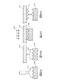
- 2A to 2D are schematic views for explaining a procedure for molding a resin molded product by the step-and-repeat method.
- 3A and 3B are schematic views for explaining a procedure for molding a resin molded product by the step-and-repeat method.
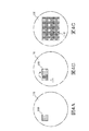
- 4A to 4C are schematic views for explaining a procedure for molding a resin molded product by the step-and-repeat method.
- 5A to 5D are schematic views for explaining a procedure for manufacturing a wafer lens in the embodiment.
- 6A to 6D are graphs showing the difference between the surface shape of the lens part molded in the first molding process and the surface shape of the lens part molded in the 180th molding process.
- the composite according to the embodiment of the present invention includes a substrate and a plurality of resin moldings formed on the substrate.
- the composite of this embodiment is a mold for manufacturing a wafer lens, a wafer lens, or the like.
- the substrate is a substantially flat member to which a plurality of resin moldings are joined.
- the shape, size, and material of the substrate are not particularly limited and can be appropriately selected according to the purpose.
- the substrate include a glass substrate, a resin substrate, a resin film, a metal substrate, a silicon substrate, and a quartz substrate.
- the substrate has optical transparency, for example, a circular glass substrate.
- the composite is a mold for manufacturing a wafer lens
- the substrate does not necessarily have to be light transmissive. However, when the resin material is irradiated with light through the mold, a light transmissive substrate is used. .
- the resin molding is formed on at least one surface of the substrate by a step-and-repeat method, and is bonded to the substrate.
- the resin molding may be formed only on one surface of the substrate, or may be formed on both surfaces.
- the shape and size of the resin molded product are not particularly limited, and can be appropriately selected according to the purpose.
- FIG. 1 is a schematic cross-sectional view showing an example of a composite according to an embodiment of the present invention (see FIG. 4C for a plan view).
- 1A and 1B are schematic cross-sectional views of a mold for producing a wafer lens.
- FIG. 1C is a schematic cross-sectional view of a wafer lens.
- the composite according to the present embodiment includes a substrate 100 and a plurality of resin moldings 110 formed on the substrate 100.
- the resin molded product 110 has molded portions 120a, b (convex portions or concave portions) having a shape corresponding to the lens portion. Have.
- the resin molded product 110 functions as a lens portion.
- the plurality of resin molded products on the substrate are arranged in an island shape, but as a result of molding by the step-and-repeat method, the plurality of resin molded products on the substrate are connected to each other. May be.
- the plurality of lens portions on the substrate are arranged in an island shape.
- a flange portion may be formed around the lens portion, and the flange portions may be adjacent to each other between adjacent lens portions. It may be connected.
- the resin molded product formed on the substrate contains A) an epoxy compound and B) an oxetane compound as a polymerizable composition, and C) a photocurable resin material containing a photopolymerization initiator.
- A) an epoxy compound and B) an oxetane compound as a polymerizable composition contains A) an epoxy compound and B) an oxetane compound as a polymerizable composition, and C) a photocurable resin material containing a photopolymerization initiator.
- One of the characteristics is that it is a cured product.
- the photocurable resin material may further contain D) a fluorosurfactant as an optional component.
- each component of the photocurable resin material will be described.
- Epoxy compound The photocurable resin material contains an epoxy compound as a main component of the polymerizable composition.
- the kind of epoxy compound is not particularly limited as long as it is cured by cationic polymerization.
- Examples of the epoxy compound that can be used as the monomer include aliphatic epoxy compounds and alicyclic epoxy compounds.
- aliphatic epoxy compounds include polyglycidyl ethers of aliphatic polyhydric alcohols or alkylene oxide adducts thereof.
- examples of such aliphatic epoxy compounds include bisphenol F diglycidyl ether, bisphenol A diglycidyl ether, 2,2′-bis (4-glycidyloxycyclohexyl) propane, 3,4-epoxycyclohexylmethyl-3,4.
- Examples of commercially available aliphatic epoxy compounds include Epolite 100MF (Kyoeisha Chemical Co., Ltd.) and EX-321L (Nagase ChemteX Corporation).
- alicyclic epoxy compounds examples include vinylcyclohexene monoxide, 1,2-epoxy-4-vinylcyclohexane, 1,2: 8,9 diepoxy limonene, 3,4-epoxycyclohexenylmethyl-3 ′, 4. '-Epoxycyclohexene carboxylate is included.
- Examples of commercially available alicyclic epoxy compounds include CEL2000, CEL3000, and CEL2021P (all of which are Daicel Chemical Industries, Ltd.).
- the content of the epoxy compound is 45 to 95% by mass, more preferably 50 to 95% by mass, and still more preferably 55 to 95% by mass with respect to the photocurable resin material.
- the epoxy compound has a higher content than the oxetane compound described later and is the main component of the resin. By doing so, it is possible to take advantage of the characteristics of the resin that the initiation reaction occurs rapidly and the hardness is high.
- the photocurable resin material contains an oxetane compound having an oxetane ring (4-membered ether) as an auxiliary component.
- an oxetane compound having an oxetane ring (4-membered ether) as an auxiliary component.
- Epoxy compounds cause an initiating reaction quickly, but since the growth reaction is slow, only oligomers having a molecular weight of about several thousand can be obtained. For this reason, the epoxy resin has hard and brittle physical properties.
- an oxetane compound hardly causes an initiation reaction, but has a fast growth reaction, so that a polymer having a molecular weight of about tens of thousands can be obtained. Therefore, when an epoxy compound in which an initiation reaction occurs quickly and an oxetane compound in which a growth reaction is fast are used in combination, a polymer having a large molecular weight can be obtained in a short time.
- the resin thus obtained has excellent toughness, it is difficult for a resin molded product to have a defective shape.
- the toughness of the resin is high, when a mold is manufactured as a composite, the mold becomes difficult to break and the life of the mold is extended.
- the type of the oxetane compound is not particularly limited, and may be appropriately selected from known oxetane compounds.
- oxetane compounds include 3-ethyl-3-hydroxymethyloxetane, 1,4-bis [ ⁇ (3-ethyl-3-oxetanyl) methoxy ⁇ methyl] benzene, 3-ethyl-3- (phenoxymethyl) oxetane Bis (3-ethyl-3-oxetanylmethyl) ether, 3-ethyl-3- (2-ethylhexyloxymethyl) oxetane, 3-ethyl- ⁇ (3-triethoxysilylpropoxy) methyl ⁇ oxetane, di [1 -Ethyl (3-oxetanyl)] methyl ether, oxetanylsilsesquioxane, phenol novolac oxetane, 1,4 bis ⁇ [(3-
- oxetanyl silsesquioxane means a silane compound having an oxetanyl group.
- oxetanylsilsesquioxane is a network-like polysiloxane having a plurality of oxetanyl groups obtained by hydrolytic condensation of the aforementioned 3-ethyl-3-[ ⁇ (3-triethoxysilyl) propoxy ⁇ methyl] oxetane. A compound.
- 3-ethyl-3-hydroxymethyl oxetane bis (3-ethyl-3-oxetanylmethyl) ether, 3-ethyl-3- ( 2-Ethylhexyloxymethyl) oxetane is preferred.
- Examples of commercially available oxetane compounds include OXT-101, OXT-211, OXT-221, OXT-212, and OXT-121 (all of which are Toagosei Co., Ltd.).
- oxetane compounds may be used alone or in combination of two or more.
- the amount of the oxetane compound is less than that of the epoxy compound as described above. Furthermore, it is preferably within the range of 1 to 45% by mass, more preferably 5 to 45% by mass, and still more preferably 10 to 30% by mass with respect to the photocurable resin material.
- the blending amount of the oxetane compound is less than 1% by mass, it becomes difficult to sufficiently exert the effect of blending the oxetane compound.
- the blending amount of the oxetane compound is more than 45% by mass, the hardness becomes low and cracking is likely to occur, which causes the resin to remain cracked in the mold when released.
- the photocurable resin material preferably contains both a monofunctional oxetane compound and a polyfunctional oxetane compound as the oxetane compound.
- a monofunctional oxetane compound By blending an appropriate amount of the monofunctional oxetane compound, it is possible to suppress the shape change due to the progress of the dark reaction.
- a polyfunctional oxetane compound By blending an appropriate amount of the polyfunctional oxetane compound, it is possible to improve the crosslink density and suppress the occurrence of shape defects.
- monofunctional oxetane compounds that can be used in combination with polyfunctional oxetane compounds include 3-ethyl-3-hydroxymethyloxetane, 3-ethyl-3- (phenoxymethyl) oxetane, 3-ethyl-3- (2- Ethylhexyloxymethyl) oxetane. These monofunctional oxetane compounds may be used alone or in combination of two or more.
- polyfunctional oxetane compounds that can be used in combination with monofunctional oxetane compounds include di [1-ethyl (3-oxetanyl)] methyl ether, 1,4 bis ⁇ [(3-ethyloxetane-3-yl ) Methoxy] methyl ⁇ oxetane.
- the blending amount of the monofunctional oxetane compound is preferably in the range of 5 to 40% by mass with respect to the photocurable resin material, and 5 to 30% by mass. % Is more preferable. Further, the blending amount of the polyfunctional oxetane compound is preferably within a range of 5 to 40% by mass, and more preferably within a range of 5 to 30% by mass with respect to the photocurable resin material.
- the total blending amount of the monofunctional oxetane compound and the polyfunctional oxetane compound is less than the blending amount of the epoxy compound and is preferably in the range of 1 to 45% by mass with respect to the photocurable resin material.
- the photocurable resin material contains a photopolymerization initiator that cationically copolymerizes an epoxy compound and an oxetane compound.
- the type of the photopolymerization initiator is not particularly limited as long as it is a photocationic polymerization initiator, and can be appropriately selected from known photocationic polymerization initiators. Examples of the photocationic polymerization initiator include sulfonium salts and iodonium salts.
- sulfonium salt-based photocationic polymerization initiators include triphenylsulfonium hexafluorophosphate, triphenylsulfonium hexafluoroantimonate, triphenylsulfonium tetrakis (pentafluorophenyl) borate, 4,4′-bis [diphenylsulfonio Diphenyl sulfide bishexafluorophosphate, 4,4′-bis [di ( ⁇ -hydroxyethoxy) phenyl sulfonio] diphenyl sulfide bishexafluoroantimonate, 4,4′-bis [di ( ⁇ -hydroxyethoxy) phenyl sulfone Nio] diphenyl sulfide bishexafluorophosphate, 7- [di (p-toluyl) sulfonio] -2-isopropylthioxanthone
- iodonium salt-based photocationic polymerization initiators include diphenyliodonium tetrakis (pentafluorophenyl) borate, diphenyliodonium hexafluorophosphate, diphenyliodonium hexafluoroantimonate, di (4-nonylphenyl) iodonium hexafluorophosphate It is.
- photocationic polymerization initiators examples include PI-2074 (Rhodia), UVI-6992 (Dow Chemical), and IRGACURE 250 (CGI-552; Ciba Specialty Chemicals).
- photopolymerization initiators may be used alone or in combination of two or more.
- the blending amount of the photopolymerization initiator is preferably in the range of 0.01 to 10% by mass, more preferably in the range of 0.05 to 10% by mass, and 0.05 to 5% with respect to the photocurable resin material. It is more preferably in the range of mass%, more preferably 0.1 to 5 mass%, and further preferably 0.1 to 1 mass%.
- the photocurable resin material may contain a fluorosurfactant.
- blending a fluorine-type surfactant the mold release property of a resin molding can be improved.
- the type of the fluorosurfactant is not particularly limited, and various conventionally known types are used. Examples of commercially available fluorosurfactants include F-444 (DIC Corporation).
- the fluorosurfactants may be used alone or in combination of two or more.
- the blending amount of the fluorosurfactant is preferably within a range of 0.01 to 5% by mass, more preferably within a range of 0.03 to 5% by mass, with respect to the photocurable resin material. More preferably within the range of 1% by mass.
- the composite of this embodiment is manufactured by the following procedure.
- the manufacturing method of the composite body of this embodiment includes: 1) a first step of forming a plurality of resin moldings on a substrate by a step-and-repeat method; and 2) a substrate on which a resin molding is formed. A second step of aging the substrate at room temperature, and 3) a third step of heating and aging the substrate on which the resin molded product is formed.
- each step will be described.
- First Step In the first step, at least one of a polymerizable composition and a photocation containing an epoxy compound as a main component and an oxetane compound as a subcomponent between a light-transmitting substrate and a mold.
- a photocurable resin material made of a polymerization initiator is interposed, light is irradiated through at least one of the substrate and the mold to cure the photocurable resin material, and the mold is released to release the photocurable resin.
- a process of obtaining a resin molded product made of a cured material of the material is made of a cured product of a photocurable resin material on at least one surface of the substrate by a step-and-repeat method that repeats while changing the facing position of the mold on the substrate.
- a plurality of resin moldings are formed (step and repeat process). This process is performed, for example, by repeating a molding process including a) a dispensing process, b) an imprint process, c) an exposure process, and d) a mold release process a plurality of times.
- FIGS. 2 to 4 show how a wafer lens mold having a convex molding part is manufactured, but a wafer lens mold having a concave molding part and a wafer lens are manufactured in the same procedure. can do.
- the photocurable resin material 210 is supplied onto a molding die 200 having a molding portion having a shape corresponding to the resin molding 110 or onto the substrate 100.
- the epoxy compound is 45 to 95% by mass
- the oxetane compound is 1 to 45% by mass
- the photocationic polymerization initiator is 0.01 to 10% by mass.
- a composition containing more epoxy compound than the oxetane compound is used.
- it is preferable that a release layer is provided in advance on the optical transfer surface of the mold 200 or a release process is performed.
- the molding die 200 is pressed against the substrate 100 to transfer the shape of the molding part of the molding die 200 to the resin material 210.
- the mold 200 may be moved, or the substrate 100 may be moved.
- the resin material 210 interposed between the mold 200 and the substrate 100 is irradiated with light 220 (for example, ultraviolet rays) to cure the resin material 210.
- light 220 for example, ultraviolet rays
- light may be irradiated from the substrate 100 side, or light may be irradiated from the mold 200 side.
- a substrate formed of a light-transmitting material is used as the substrate 100 or the mold 200 on the light irradiation side.
- FIGS. 3A and 3B After the above steps a) to d) are completed, as shown in FIGS. 3A and 3B, the position of the molding die 200 is shifted, the opposing position of the molding die on the substrate is changed, and the dispensing step, A printing process, an exposure process, and a release process are performed.
- FIG. 3A shows a state where the second molding step is being performed
- FIG. 3B shows a state where the third molding step is being performed.
- the time required for one molding process is, for example, about 1 to 5 minutes.
- the above molding process is repeated while changing the position of the mold 200.
- the number of times the molding process is repeated is not particularly limited, but is, for example, 10 times or more, and preferably 50 to 200 times.
- a large number of resin molded products 110 can be formed on one substrate 100 (see FIG. 4C).
- the composite (substrate on which the resin molded product is formed) obtained in the first step is left at room temperature (room temperature aging step). Specifically, the composite is left at a temperature of 15 to 30 ° C. for a predetermined time.
- room temperature aging step Specifically, the composite is left at a temperature of 15 to 30 ° C. for a predetermined time.
- a dark reaction proceeds in each resin molded product, and the degree of cure of each resin molded product becomes substantially the same. For example, if you try to form a large number of optical transfer surfaces corresponding to thousands of lens parts using a mold that has about 10 to 300 molded parts, all the optical transfer surfaces have been molded. It takes a long time to do.
- the plurality of resin molded products on one substrate are in a state where there is a difference in the degree of curing. For this reason, the dispersion
- the room temperature aging time should be at least 0.5 times the time required for the first step. For example, when the first step takes 2 hours, room temperature aging is performed for at least 1 hour. When the first step takes 10 hours, room temperature aging is performed for at least 5 hours. It should be noted that, by taking a long room temperature aging time, it is possible to reduce the variation in shape between the resin moldings. However, if the room temperature aging time reaches several tens of hours and becomes too long, it is not suitable for practical use. On the other hand, if the room temperature aging time is too short, the variation in shape between the resin moldings remains, and the process proceeds to the next step. Homogeneous characteristics cannot be obtained.
- the dark reaction time is short. Therefore, the room temperature aging time does not become so long that it is practically used, and by performing room temperature aging for at least the above time, the degree of curing of the resin molding is sufficiently increased, and the degree of curing between the resin moldings varies. Can be reduced.
- the upper limit of the room temperature aging treatment time is not limited to this, but from the practical point of view, it is preferably about 6 times the first step and about 20 hours at the longest.
- Room temperature aging is preferably performed in a low-humidity environment in order to avoid the influence of shape change accompanying changes in humidity.
- it may be performed in an atmospheric pressure environment with a humidity of 10% or less, or in a reduced pressure environment of 5 KPa or less, more preferably 1 KPa or less.
- the composite that has been aged at room temperature in the second step is heated (heating aging step). Specifically, the composite is heated at 50 to 200 ° C. for a predetermined time in a low oxygen environment. By this step, the reaction of the uncured functional group can be promoted, the stress in each resin molded product can be relaxed, and each resin molded product can be stabilized.
- the heat aging time is preferably 1 to 3 hours from the viewpoint of exhibiting the effect of aging and avoiding a decrease in productivity and quality change of the resin. Heat aging is performed in a low oxygen environment.
- heat aging may be performed under a reduced pressure environment of 5 KPa or less, more preferably 1 KPa or less, or an environment substituted with an inert gas such as nitrogen.
- the replacement with the inert gas can be realized, for example, by injecting the inert gas up to normal pressure after the reduced pressure environment described above.
- heat treatment is performed when forming a mold release layer provided on the mold or an underlayer for forming the mold release layer. You may make it also serve as an aging process.
- the composite of this embodiment can be manufactured by the above procedure.
- a resin molded product is formed using a resin (epoxy resin and oxetane resin) that is cured by cationic polymerization. Therefore, in the composite of the present embodiment, the resin caused by 1) insufficient curing inside the resin material due to insufficient exposure, 2) inhibition of curing of the resin material surface due to oxygen in the atmosphere, and 3) resin shrinkage after curing, etc. Form defects (sinks, wrinkles, cracks, etc.) are difficult to occur.
- a resin molded product is formed using a combination of an epoxy resin and an oxetane resin.
- the resin molded product thus formed has a high degree of curing immediately after molding and a short time required for the dark reaction. Therefore, even if a plurality of resin molded products are formed on the substrate by the step-and-repeat method, the variation in the shape of the resin molded products is small.
- the method for manufacturing a composite according to the present embodiment room temperature aging is performed as the second step and heat aging is performed as the third step after molding the resin molded product by the step-and-repeat method. Therefore, the method for producing a composite according to the present embodiment can sufficiently increase the degree of cure of the resin molded product, and can relieve stress in each resin molded product and stabilize each resin molded product. Moreover, the processing time does not become too long.
- a mold for a wafer lens with a variation in the shape of the molded portion is on the order of tens of nanometers, Wafer lenses and the like can be manufactured.
- the wafer lens may have a lens portion formed on both sides of the substrate, or may be a laminate of a plurality of wafer lenses. Then, the wafer lens and the laminated body of the plurality of wafer lenses manufactured in this way can be cut for each lens unit or in units of a plurality of lens units to obtain a lens unit used for an imaging camera or the like.
- a surface having a molding part on which a molding part (spherical concave surface having a diameter of 3 mm and a depth of 0.3 mm) corresponding to the lens part is formed is set in a molding apparatus.
- a photo-curable resin material (any one of the resin materials described in Table 1) was dropped onto the substrate (see FIG. 5A).
- the mold was pressed against the glass substrate, and the molding part (concave part) of the mold was filled with the photocurable resin material (see FIG. 5B).
- the photocurable resin material is cured by irradiating the photocurable resin material in the molded part with ultraviolet rays (illuminance: 200 mW / cm 2 ) using an ultra-high pressure mercury lamp (peak wavelength 365 nm).
- the ultraviolet irradiation time was set for each resin material by conducting a preliminary experiment and setting the minimum time required for curing the resin. Specifically, Examples 1 and 3 were 90 seconds, Example 2 was 120 seconds, and Comparative Example 1 was 300 seconds.
- the resin molded product (lens portion) bonded to the glass substrate was released from the resin mold (see FIG. 5D). The above molding steps 1) to 4) were repeated 180 times while changing the position of the molding die to form a plurality of lens portions made of a photocurable resin on the glass substrate (see FIG. 1C).
- Table 2 shows the time (molding time) required to perform the molding steps 1) to 4) once for each resin material.
- the molding process was repeated 180 times, so the net time required for molding was 270 minutes (2.5 hours).
- the net time required for molding was 360 minutes (6 hours).
- the resin material of Comparative Example 1 was used, when the molding process was repeated 180 times, the net time required for molding was 900 minutes (15 hours).
- a room temperature (24 ° C.), a glass substrate on which a plurality of lens portions were formed was left for 12 hours under a reduced pressure environment of 1 KPa (room temperature aging). Subsequently, the glass substrate in which the several lens part was formed was left still for 1 hour in the pressure-reduced environment of 100 degreeC and 1 KPa (heating aging).
- FIG. 6 shows the surface shape of the lens part molded in the molding process of the first molding process (curve indicated by “1”) and the surface shape of the lens part molded in the 180th molding process (curve indicated by “180”). It is a graph which shows the difference of).
- the horizontal axis represents the distance (unit: mm) from the center of the lens unit, and the vertical axis represents the difference (unit: ⁇ m) between the surface height and the design value.
- 6A shows the measurement result of the wafer lens of Example 1
- FIG. 6B shows the measurement result of the wafer lens of Example 2
- FIG. 6C shows the measurement result of the wafer lens of Example 3
- FIG. show the measurement results of the wafer lens of Comparative Example 1.
- the shape of the lens part molded in the first molding process is significantly different from that of the lens part molded in the 180th molding process.
- the shape difference of the site with the largest change was about 400 nm.
- the shape difference of the portion with the largest change was about 100 nm.
- Table 2 shows the molding time per time and the maximum shape difference between the lens part molded in the first molding process and the lens part molded in the 180th molding process.
- the molding time per time was evaluated as ⁇ for less than 100 seconds, ⁇ for 100 seconds to less than 250 seconds, and ⁇ for 250 seconds or more.
- ⁇ when the shape difference is less than 100 nm and no white turbidity is observed ⁇ , when the shape difference is less than 100 nm but slightly cloudy or the like is observed, the shape difference is less than 100 nm It was evaluated as ⁇ when the white turbidity was present and at a practically acceptable level, ⁇ when the shape difference was 100 nm or more and less than 200 nm, and ⁇ when the shape difference was 200 nm or more.
- the wafer lenses of Examples 1 to 3 using a photocurable resin material containing an oxetane compound have a short molding time of less than 2 minutes and a difference in shape of the lens part.
- the wafer lens of Comparative Example 1 using a photocurable resin material that does not contain an oxetane compound has a long molding time of 5 minutes, and the shape difference of the lens part is as large as about 400 nm. It was.
- Comparative Example 1 when the shape difference was measured under the same conditions except that the room temperature aging was set to 100 hours, it was confirmed that the shape difference was relaxed to about 200 nm but was not suitable for actual use. .
- the method for producing a composite and the composite of the present invention are useful, for example, in the production of a wafer lens or a mold for producing a wafer lens.
Landscapes
- Physics & Mathematics (AREA)
- Engineering & Computer Science (AREA)
- General Physics & Mathematics (AREA)
- Chemical & Material Sciences (AREA)
- Mechanical Engineering (AREA)
- Optics & Photonics (AREA)
- Chemical Kinetics & Catalysis (AREA)
- Medicinal Chemistry (AREA)
- Polymers & Plastics (AREA)
- Organic Chemistry (AREA)
- Health & Medical Sciences (AREA)
- Manufacturing & Machinery (AREA)
- Casting Or Compression Moulding Of Plastics Or The Like (AREA)
Abstract
重合性組成物と重合開始剤とからなる光硬化性樹脂材料を介して基板に対して相対的に成形型を押圧し、光を照射して光硬化性樹脂材料を硬化させる工程を繰り返すステップアンドリピート方式により、基板の少なくとも一方の面上に光硬化性樹脂材料の硬化物からなる複数の樹脂成形物を形成する。重合性組成物は、主成分としてのエポキシ化合物と、副成分としてのオキセタン化合物とを含む。重合開始剤は、光カチオン重合開始剤からなる。
Description
本発明は、基板の少なくとも一方の面上に複数の樹脂成形物がステップアンドリピート方式で形成された複合体の製造方法および複合体に関する。
光学レンズの製造分野においては、ガラス基板の表面に硬化性樹脂からなるレンズ部を形成することで、耐熱性の高い光学レンズを製造する技術が知られている。この技術を適用した光学レンズの製造方法として、6インチ径、8インチ径、12インチ径などのウエハサイズのガラス円板などの基板を使用し、基板の表面に硬化性樹脂からなるレンズ部を複数形成した、いわゆる「ウエハレンズ」を製造する方法が提案されている(例えば、特許文献1参照)。ウエハレンズを製造した後、ウエハレンズのガラス基板を切断してレンズ部ごとに分割することで、多数の光学レンズを一度に得ることができる。
特許文献1には、マスター成形型(金型)に加えて、さらに2種類の中間成形型(サブマスター成形型およびサブサブマスター成形型)を用いてウエハレンズを製造する方法が記載されている。特許文献1に記載の製造方法では、まず、ウエハレンズのレンズ部に対応するネガ形状の成形部を有するマスター成形型を用いて、光硬化性樹脂からなるポジ形状の成形部を基板上に成形することで、サブマスター成形型を製造する。次いで、サブマスター成形型を用いて、光硬化性樹脂からなるネガ形状の成形部を基板上に成形することで、サブサブマスター成形型を製造する。最後に、サブサブマスター成形型を用いて、光硬化性樹脂からなるレンズ部をガラス基板上に成形することで、ウエハレンズを製造する。
このようにマスター成形型を用いてレンズ部を成形するのではなく、中間成形型を用いてレンズ部を成形することで、マスター成形型の使用回数を低減することができる。その結果、高価なマスター成形型の劣化を防ぐことができ、製造コストを低減することができる。
特許文献1に記載の製造方法では、小さなマスター成形型を用いて大きな中間成形型(サブマスター成形型)を製造するために、小さな成形型を用いて基板上の成形型の対向位置を変えながら成形を繰り返す、いわゆるステップアンドリピート方式で複数の樹脂成形物を大きな基板上に成形している。
光硬化性樹脂材料を用いた場合のステップアンドリピート方式による樹脂成形物の成形は、a)ディスペンス工程、b)インプリント工程、c)露光工程(硬化工程)およびd)離型工程を含む成形工程を、基板上の成形型の対向位置を変えて複数回繰り返すことで行われる。まず、ウエハレンズのレンズ部に対応するネガ形状の成形部を有するマスター成形型の上に光硬化性樹脂材料を滴下する(ディスペンス工程)。次いで、マスター成形型を基板に押し付けて、マスター成形型の成形部の形状を光硬化性樹脂材料に転写する(インプリント工程)。次いで、樹脂材料に光を照射して、樹脂材料を硬化させる(露光工程)。次いで、マスター成形型と基板とを離して、光硬化性樹脂からなる成形部をマスター成形型から離型する(離型工程)。樹脂成形物は、離型後も基板に接合されている。
以上の成形工程を終えた後、マスター成形型の位置をずらし、再度ディスペンス工程、インプリント工程、露光工程および離型工程を行う。以後、マスター成形型の位置を変えながら上記成形工程を繰り返す。以上の手順により、大きな基板の上に多数の成形部が形成された中間成形型(サブマスター成形型)を製造することができる。
一般に、何千個ものレンズ部に対応する多数の光学転写面を一度に成形しようとすると、それに対応した大型のマスター金型の加工が難しくなったり、マスター金型が非常に高価になったりする。しかし、数十個程度のレンズ部形成用の光学転写面を持つ小型のマスター金型であれば加工が容易であり、小型のマスター金型を用いてステップアンドリピート方式で成形型を作製すると、何千個ものレンズ部に対応した多数の光学転写面を持つ成形型を比較的容易に得ることができる。
ウエハレンズの製造では、レンズ部の形状を高精度に制御することが求められる(形状誤差の許容範囲が数十nm~数百nmレベル)。特に、近年は、撮像レンズの高性能化の観点から、レンズ形状の正確性が強く要求されている(形状誤差の許容範囲が数十nm~百数十nmレベル)。高性能化のために、基板の両面にレンズ部を形成したり、ウエハレンズを複数積層したりする場合は、この要求がさらに強くなる。したがって、ウエハレンズを製造するための中間成形型を製造する場合も、各樹脂成形物の形状を高精度に制御することが求められる。
本発明者の予備実験によれば、ラジカル重合で硬化する樹脂(例えば、アクリル樹脂やポリジメチルシロキサンなど)を使用して基板上に複数の成形部を形成した場合、成形部の形状不良(ヒケ、シワ、割れなど)が起きやすいことがわかった。この形状不良は、1)露光不足による樹脂材料内部の硬化不足、2)大気中の酸素による樹脂材料表面の硬化阻害、および3)硬化後の樹脂収縮に起因するものと推察される。
本発明者がさらに検討したところ、カチオン重合で硬化するエポキシ樹脂材料を使用することで、上記1)~3)の問題を解消できることがわかった。しかしながら、エポキシ樹脂材料を使用し、かつステップアンドリピート方式で複数の樹脂成形物を形成した場合、各樹脂成形物の形状がばらついてしまうことが判明した。
この形状のばらつきは、以下の1)および2)の理由によるものと推察される。1)エポキシ樹脂は光照射による到達硬化度が低く、成形後も長時間暗反応が進行する。このため、最初に成形した樹脂成形物と、最後に成形した樹脂成形物との間では、硬化度が異なり、形状も異なる。暗反応を進行させて硬化度を揃えようとすると、極めて長い時間を必要とするため、実用的な製造時間の範囲内では硬化度のばらつきを解消できず、ウエハレンズまたはその成形型を低コストで得ることができなくなる。2)2回目以降の成形工程において、それ以前に成形された樹脂成形物に光が照射されることによって、樹脂成形物の形状が変わってしまう。なお、成形済みの部位に光が照射されるのを防止しようとしても、金型によって反射または散乱された光が成形済みの部位に侵入してしまうことや、基板が光透過性を有する場合は、基板を通じて成形済みの部位に光が漏れ出すこと、1枚のウエハレンズからのレンズの取り数を多くした場合は、隣り合う樹脂成形物間の間隔が小さくなるため、光漏れが防ぎにくくなること、などの理由で、成形済みの部位に光が照射されるのを十分に防ぐことは難しい。
以上のように、ウエハレンズ製造用の成形型を製造する際に、エポキシ樹脂を使用することで、樹脂成形物の形状不良を抑制することができるものの、エポキシ樹脂を使用して、かつステップアンドリピート方式でウエハレンズ製造用の成形型を製造すると、同一の基板上に形成された各樹脂成形物の形状がばらついてしまうことがある。特に、ウエハレンズの製造においては、低コストでレンズを製造することが求められており、1枚の基板上に形成されるレンズ部の個数を多くするため、ステップアンドリピートの繰り返し回数が多くなる。したがって、すべての樹脂成形物の成形には非常に時間が掛かることが避けられず、このような問題が顕著に発生する。このような樹脂成形物の形状のばらつきは、高品質のウエハレンズを製造する上で問題である。
本発明の目的は、基板上に複数の樹脂成形物がステップアンドリピート方式で形成された複合体であって、樹脂成形物の形状のばらつきが小さい複合体を得ることのできる製造方法を提供することである。
本発明の複合体の製造方法は、基板の少なくとも一方の面上に複数の樹脂成形物が形成された複合体の製造方法であって、少なくとも一方が光透過性の基板および成形型の間に、主成分としてのエポキシ化合物と副成分としてのオキセタン化合物とを含む重合性組成物および光カチオン重合開始剤からなる光硬化性樹脂材料を介在させ、前記基板および成形型のうち少なくとも一方を介して光を照射して前記光硬化性樹脂材料を硬化させ、前記成形型を離型して前記光硬化性樹脂材料の硬化物からなる樹脂成形物を得る工程を、前記基板上の前記成形型の対向位置を変えて繰り返すことにより、前記光硬化性樹脂材料の硬化物からなる複数の樹脂成形物を形成する第1の工程と、前記第1の工程の後に、前記複数の樹脂成形物を形成された基板を、15~30℃の温度で、低湿環境下において前記第1の工程に掛かった時間の0.5倍以上の時間放置する第2の工程と、前記第2の工程の後に、前記複数の樹脂成形物を形成された基板を、低酸素環境下において50~200℃で加熱する第3の工程と、を有する。
本発明の複合体は、本発明の複合体の製造方法によって得られた複合体であって、前記複数の樹脂成形物が、それぞれレンズ部であること、またはそれぞれレンズ部を成形するための成形型の光学転写面を有することを特徴とする。
本発明によれば、ステップアンドリピート方式を用いて基板上に形成された複数の樹脂成形物であって、それら樹脂成形物の相互の形状のばらつきが小さい複合体を提供することができる。たとえば、本発明によれば、成形部の形状のばらつきが小さいウエハレンズ製造用の成形型や、レンズ部の形状のばらつきが小さいウエハレンズなどを提供することができる。
1.複合体
本発明の実施形態に係る複合体は、基板と、基板の上に形成された複数の樹脂成形物とを有する。たとえば、本実施形態の複合体は、ウエハレンズ製造用の成形型やウエハレンズなどである。
本発明の実施形態に係る複合体は、基板と、基板の上に形成された複数の樹脂成形物とを有する。たとえば、本実施形態の複合体は、ウエハレンズ製造用の成形型やウエハレンズなどである。
基板は、複数の樹脂成形物が接合される略平板状の部材である。基板の形状、大きさおよび材料は、特に限定されず、目的に応じて適宜選択されうる。基板の例には、ガラス基板、樹脂基板、樹脂フィルム、金属基板、シリコン基板、石英基板が含まれる。複合体がウエハレンズである場合、基板は光透過性を有するものであり、例えば円形状のガラス基板である。複合体がウエハレンズ製造用の成形型である場合、基板は必ずしも光透過性を有していなくてもよいが、成形型を通して樹脂材料に光照射する場合は、光透過性の基板を使用する。
樹脂成形物は、基板の少なくとも一方の面上にステップアンドリピート方式で形成されており、基板に接合されている。樹脂成形物は、基板の一方の面にのみ形成されていてもよいし、両方の面に形成されていてもよい。樹脂成形物の形状および大きさは、特に限定されず、目的に応じて適宜選択されうる。
図1は、本発明の実施形態に係る複合体の例を示す断面模式図である(平面図については図4Cを参照)。図1Aおよび図1Bは、ウエハレンズ製造用の成形型の断面模式図である。図1Cは、ウエハレンズの断面模式図である。これらの図に示されるように、本実施形態の複合体は、基板100と、基板100の上に形成された複数の樹脂成形物110を有する。図1Aおよび図1Bに示されるように、複合体がウエハレンズ製造用の成形型である場合、樹脂成形物110は、レンズ部に対応する形状の成形部120a,b(凸部または凹部)を有する。一方、図1Cに示されるように、複合体がウエハレンズである場合、樹脂成形物110は、レンズ部として機能する。なお、図1Aおよび図1Bにおいては、基板上の複数の樹脂成形物が島状に配置されているが、ステップアンドリピート方式によって成形を行った結果、基板上の複数の樹脂成形物が互いに接続されていてもよい。また、図1Cにおいては、基板上の複数のレンズ部が島状に配置されているが、レンズ部の周囲にフランジ部を形成してもよいし、隣り合うレンズ部間でフランジ部同士が互いに接続されていてもよい。
本実施形態の複合体は、基板上に形成された樹脂成形物が、重合性組成物としてA)エポキシ化合物およびB)オキセタン化合物を含み、さらにC)光重合開始剤を含む光硬化性樹脂材料の硬化物であることを一つの特徴とする。光硬化性樹脂材料は、任意成分として、さらにD)フッ素系界面活性剤を含んでいてもよい。以下、光硬化性樹脂材料の各成分について説明する。
A)エポキシ化合物
光硬化性樹脂材料は、重合性組成物の主たる成分としてエポキシ化合物を含む。エポキシ化合物の種類は、カチオン重合により硬化するものであれば特に限定されない。モノマーとして使用しうるエポキシ化合物の例としては、脂肪族エポキシ化合物や脂環式エポキシ化合物などが挙げられる。
光硬化性樹脂材料は、重合性組成物の主たる成分としてエポキシ化合物を含む。エポキシ化合物の種類は、カチオン重合により硬化するものであれば特に限定されない。モノマーとして使用しうるエポキシ化合物の例としては、脂肪族エポキシ化合物や脂環式エポキシ化合物などが挙げられる。
脂肪族エポキシ化合物の例としては、脂肪族多価アルコールまたはそのアルキレンオキサイド付加物のポリグリシジルエーテルが挙げられる。そのような脂肪族エポキシ化合物の例には、ビスフェノールFジグリシジルエーテル、ビスフェノールAジグリシジルエーテル、2,2’-ビス(4-グリシジルオキシシクロヘキシル)プロパン、3,4-エポキシシクロヘキシルメチル-3,4-エポキシシクロヘキサンカーボキシレート、ビニルシクロヘキセンジオキシド、2-(3,4-エポキシシクロヘキシル)-5,5-スピロ-(3,4-エポキシシクロヘキサン)-1,3-ジオキサン、ビス(3,4-エポキシシクロヘキシル)アジペート、1,2-シクロプロパンジカルボン酸ビスグリシジルエステル、エチレングリコールジグリシジルエーテル、ジエチレングリコールジグリシジルエーテル、プロピレングリコールジグリシジルエーテル、トリプロピレングリコールジグリシジルエーテル、ネオペンチルグリコールジグリシジルエーテル、1,4-ブタンジオールジグリシジルエーテル、1,6-ヘキサンジオールジグリシジルエーテル、トリメチロールプロパントリグリシジルエーテル、トリメチロールプロパンジグリシジルエーテル、ポリエチレングリコールジグリシジルエーテルが含まれる。
脂肪族エポキシ化合物の市販品としては、例えば、エポライト100MF(共栄社化学株式会社)、EX-321L(ナガセケムテックス株式会社)が挙げられる。
脂環式エポキシ化合物の例には、ビニルシクロヘキセンモノオキサイド、1,2-エポキシ-4-ビニルシクロヘキサン、1,2:8,9ジエポキシリモネン、3,4-エポキシシクロヘキセニルメチル-3’,4’-エポキシシクロヘキセンカルボキシレートが含まれる。
脂環式エポキシ化合物の市販品としては、例えば、CEL2000、CEL3000、CEL2021P(いずれもダイセル化学工業株式会社)が挙げられる。
エポキシ化合物の含有量は、光硬化性樹脂材料に対して、45~95質量%、より好ましくは50~95質量%、さらに好ましくは55~95質量%とするのがよい。エポキシ化合物は、後述するオキセタン化合物よりも含有量を多くして樹脂の主成分とする。このようにすることで、開始反応が速やかに生じ、かつ、硬度が高いという樹脂の特性を活かすことができる。
B)オキセタン化合物
光硬化性樹脂材料は、エポキシ化合物に加えて、オキセタン環(4員環エーテル)を有するオキセタン化合物を副成分として含む。次に説明するように、エポキシ化合物とオキセタン化合物とを組み合わせて使用することで、エポキシ化合物の欠点を補うことができる。
光硬化性樹脂材料は、エポキシ化合物に加えて、オキセタン環(4員環エーテル)を有するオキセタン化合物を副成分として含む。次に説明するように、エポキシ化合物とオキセタン化合物とを組み合わせて使用することで、エポキシ化合物の欠点を補うことができる。
エポキシ化合物は、開始反応が速やかに生じるが、成長反応が遅いため、分子量が数千程度のオリゴマーしか得ることができない。このため、エポキシ樹脂は、堅くて脆い物性となる。一方、オキセタン化合物は、開始反応は生じにくいが、成長反応が速いため、分子量が数万程度のポリマーを得ることができる。そこで、開始反応が速やかに生じるエポキシ化合物と、成長反応が速いオキセタン化合物とを組み合わせて使用すると、短時間で、分子量が大きいポリマーを得ることができる。このようにして得られた樹脂は優れた靭性を有するため、樹脂成形物の形状不良が生じにくい。また、樹脂の靭性が高いので、複合体として成形型を製造する場合は、成形型が割れにくくなり、成形型の寿命も長くなる。
また、エポキシ化合物とオキセタン化合物とを組み合わせて使用すると、短時間で高い硬化度に到達する。このため、暗反応に要する時間が短くなる。したがって、ステップアンドリピート方式で複数の樹脂成形物を成形しても、各樹脂成形物の形状のばらつきが小さくなる。
オキセタン化合物の種類は、特に限定されず、公知のオキセタン化合物から適宜選択されうる。オキセタン化合物の例には、3-エチル-3-ヒドロキシメチルオキセタン、1,4-ビス[{(3-エチル-3-オキセタニル)メトキシ}メチル]ベンゼン、3-エチル-3-(フェノキシメチル)オキセタン、ビス(3-エチル-3-オキセタニルメチル)エーテル、3-エチル-3-(2-エチルヘキシロキシメチル)オキセタン、3-エチル-{(3-トリエトキシシリルプロポキシ)メチル}オキセタン、ジ[1-エチル(3-オキセタニル)]メチルエーテル、オキセタニルシルセスキオキサン、フェノールノボラックオキセタン、1,4ビス{[(3-エチルオキセタン-3-イル)メトキシ]メチル}オキセタンが含まれる。ここで「オキセタニルシルセスキオキサン」とは、オキセタニル基を有するシラン化合物を意味する。たとえば、オキセタニルシルセスキオキサンは、前述の3-エチル-3-[{(3-トリエトキシシリル)プロポキシ}メチル]オキセタンを加水分解縮合させることにより得られる、オキセタニル基を複数有するネットワーク状ポリシロキサン化合物である。これらのオキセタン化合物の中でも、良好な靭性を付与でき、かつ入手が容易な、3-エチル-3-ヒドロキシメチルオキセタン、ビス(3-エチル-3-オキセタニルメチル)エーテル、3-エチル-3-(2-エチルヘキシロキシメチル)オキセタンが好ましい。
オキセタン化合物の市販品としては、例えば、OXT-101、OXT-211、OXT-221、OXT-212、OXT-121(いずれも東亞合成株式会社)が挙げられる。
これらのオキセタン化合物は、単独で使用してもよいし、2種以上を組み合わせて使用してもよい。オキセタン化合物の配合量は、上述したようにエポキシ化合物よりも少なくする。さらに、光硬化性樹脂材料に対して、1~45質量%の範囲内が好ましく、5~45質量%がより好ましく、10~30質量%がさらに好ましい。オキセタン化合物の配合量が1質量%未満の場合、オキセタン化合物を配合することによる効果を十分に発揮させにくくなる。一方、オキセタン化合物の配合量が45質量%超の場合、硬度が低くなって割れを生じやすくなり、離型する際に型に樹脂が割れ残る原因になる。また、成形型として使用する場合に、十分な耐久性が得られなくなり何度も繰り返し使用することが難しくなるおそれがある。オキセタン化合物の配合量を上記のようにすることで、ほぼビッカース硬度10以上の硬度を確保することができ、割れや耐久性の問題を低減することができる。
光硬化性樹脂材料は、オキセタン化合物として、単官能オキセタン化合物および多官能オキセタン化合物の両方を含むことが好ましい。適量の単官能オキセタン化合物を配合することで、暗反応の進行による形状変化を抑制することができる。一方、適量の多官能オキセタン化合物を配合することで、架橋密度を向上させて、形状不良の発生を抑制することができる。
多官能オキセタン化合物と組み合わせて使用しうる単官能オキセタン化合物の例には、3-エチル-3-ヒドロキシメチルオキセタン、3-エチル-3-(フェノキシメチル)オキセタン、3-エチル-3-(2-エチルヘキシロキシメチル)オキセタンが含まれる。これらの単官能オキセタン化合物は、単独で使用してもよいし、2種以上を組み合わせて使用してもよい。また、単官能オキセタン化合物と組み合わせて使用しうる多官能オキセタン化合物の例には、ジ[1-エチル(3-オキセタニル)]メチルエーテル、1,4ビス{[(3-エチルオキセタン-3-イル)メトキシ]メチル}オキセタンが含まれる。
単官能オキセタン化合物と多官能オキセタン化合物とを組み合わせて使用する場合、単官能オキセタン化合物の配合量は、光硬化性樹脂材料に対して、5~40質量%の範囲内が好ましく、5~30質量%の範囲内がより好ましい。また、多官能オキセタン化合物の配合量は、光硬化性樹脂材料に対して、5~40質量%の範囲内が好ましく、5~30質量%の範囲内がより好ましい。前述の通り、単官能オキセタン化合物および多官能オキセタン化合物の合計配合量は、エポキシ化合物の配合量よりも少なく、かつ、光硬化性樹脂材料に対して、1~45質量%の範囲内が好ましい。
C)光重合開始剤
光硬化性樹脂材料は、エポキシ化合物およびオキセタン化合物をカチオン共重合させる光重合開始剤を含む。光重合開始剤の種類は、光カチオン重合開始剤であれば特に限定されず、公知の光カチオン重合開始剤から適宜選択されうる。光カチオン重合開始剤の例には、スルホニウム塩、ヨードニウム塩が含まれる。
光硬化性樹脂材料は、エポキシ化合物およびオキセタン化合物をカチオン共重合させる光重合開始剤を含む。光重合開始剤の種類は、光カチオン重合開始剤であれば特に限定されず、公知の光カチオン重合開始剤から適宜選択されうる。光カチオン重合開始剤の例には、スルホニウム塩、ヨードニウム塩が含まれる。
スルホニウム塩系の光カチオン重合開始剤の例には、トリフェニルスルホニウムヘキサフルオロホスフェート、トリフェニルスルホニウムヘキサフルオロアンチモネート、トリフェニルスルホニウムテトラキス(ペンタフルオロフェニル)ボレート、4,4’-ビス〔ジフェニルスルホニオ〕ジフェニルスルフィドビスヘキサフルオロホスフェート、4,4’-ビス[ジ(β-ヒドロキシエトキシ)フェニルスルホニオ]ジフェニルスルフィドビスヘキサフルオロアンチモネート、4,4’-ビス[ジ(β-ヒドロキシエトキシ)フェニルスルホニオ]ジフェニルスルフィドビスヘキサフルオロホスフェート、7-[ジ(p-トルイル)スルホニオ]-2-イソプロピルチオキサントンヘキサフルオロアンチモネート、7-[ジ(p-トルイル)スルホニオ]-2-イソプロピルチオキサントンテトラキス(ペンタフルオロフェニル)ボレート、4-フェニルカルボニル-4’-ジフェニルスルホニオ-ジフェニルスルフィドヘキサフルオロホスフェート、4-(p-tert-ブチルフェニルカルボニル)-4’-ジフェニルスルホニオ-ジフェニルスルフィドヘキサフルオロアンチモネート、4-(p-tert-ブチルフェニルカルボニル)-4’-ジ(p-トルイル)スルホニオ-ジフェニルスルフィド テトラキス(ペンタフルオロフェニル)ボレートが含まれる。ヨードニウム塩系の光カチオン重合開始剤の例には、ジフェニルヨードニウムテトラキス(ペンタフルオロフェニル)ボレート、ジフェニルヨードニウムヘキサフルオロホスフェート、ジフェニルヨードニウムヘキサフルオロアンチモネート、ジ(4-ノニルフェニル)ヨードニウムヘキサフルオロホスフェートが含まれる。
光カチオン重合開始剤の市販品としては、例えば、PI-2074(Rhodia社)、UVI-6992(Dow Chemical社)、IRGACURE 250(CGI-552;Ciba Specialty Chemicals社)が挙げられる。
これらの光重合開始剤は、単独で使用してもよいし、2種以上を組み合わせて使用してもよい。光重合開始剤の配合量は、光硬化性樹脂材料に対して、0.01~10質量%の範囲内が好ましく、0.05~10質量%の範囲内がより好ましく、0.05~5質量%の範囲内がさらに好ましく、0.1~5質量%がさらに好ましく、0.1~1質量%がさらに好ましい。
D)フッ素系界面活性剤
前述の通り、光硬化性樹脂材料は、フッ素系界面活性剤を含んでいてもよい。フッ素系界面活性剤を配合することで、樹脂成形物の離型性を向上させることができる。
前述の通り、光硬化性樹脂材料は、フッ素系界面活性剤を含んでいてもよい。フッ素系界面活性剤を配合することで、樹脂成形物の離型性を向上させることができる。
フッ素系界面活性剤の種類は、特に限定されず、従来公知の各種のものが用いられる。フッ素系界面活性剤の市販品としては、例えば、F-444(DIC株式会社)が挙げられる。
これらのフッ素系界面活性剤は、単独で使用してもよいし、2種以上を組み合わせて使用してもよい。フッ素系界面活性剤の配合量は、光硬化性樹脂材料に対して、0.01~5質量%の範囲内が好ましく、0.03~5質量%の範囲内がより好ましく、0.03~1質量%の範囲内がさらに好ましい。
本実施形態の複合体は、以下の手順により製造される。
2.複合体の製造方法
本実施形態の複合体の製造方法は、1)基板上に複数の樹脂成形物をステップアンドリピート方式で形成する第1の工程と、2)樹脂成形物を形成された基板を室温でエージングする第2の工程と、3)樹脂成形物を形成された基板を加熱してエージングする第3の工程とを有する。以下、各工程について説明する。
本実施形態の複合体の製造方法は、1)基板上に複数の樹脂成形物をステップアンドリピート方式で形成する第1の工程と、2)樹脂成形物を形成された基板を室温でエージングする第2の工程と、3)樹脂成形物を形成された基板を加熱してエージングする第3の工程とを有する。以下、各工程について説明する。
1)第1の工程
第1の工程では、少なくとも一方が光透過性の基板および成形型の間に、主成分としてのエポキシ化合物と副成分としてのオキセタン化合物とを含む重合性組成物および光カチオン重合開始剤からなる光硬化性樹脂材料を介在させ、基板および成形型のうち少なくとも一方を介して光を照射して光硬化性樹脂材料を硬化させ、成形型を離型して光硬化性樹脂材料の硬化物からなる樹脂成形物を得る工程を、基板上の成形型の対向位置を変えながら繰り返すステップアンドリピート方式により、基板の少なくとも一方の面上に光硬化性樹脂材料の硬化物からなる複数の樹脂成形物を形成する(ステップアンドリピート工程)。この工程は、例えば、a)ディスペンス工程、b)インプリント工程、c)露光工程およびd)離型工程を含む成形工程を、複数回繰り返すことで行われる。
第1の工程では、少なくとも一方が光透過性の基板および成形型の間に、主成分としてのエポキシ化合物と副成分としてのオキセタン化合物とを含む重合性組成物および光カチオン重合開始剤からなる光硬化性樹脂材料を介在させ、基板および成形型のうち少なくとも一方を介して光を照射して光硬化性樹脂材料を硬化させ、成形型を離型して光硬化性樹脂材料の硬化物からなる樹脂成形物を得る工程を、基板上の成形型の対向位置を変えながら繰り返すステップアンドリピート方式により、基板の少なくとも一方の面上に光硬化性樹脂材料の硬化物からなる複数の樹脂成形物を形成する(ステップアンドリピート工程)。この工程は、例えば、a)ディスペンス工程、b)インプリント工程、c)露光工程およびd)離型工程を含む成形工程を、複数回繰り返すことで行われる。
以下、図2~図4を参照して、第1の工程について具体的に説明する。図2~図4では、凸状の成形部を有するウエハレンズの成形型を製造する様子を図示しているが、凹状の成形部を有するウエハレンズの成形型およびウエハレンズも同様の手順で製造することができる。
a)ディスペンス工程
まず、図2Aに示されるように、光硬化性樹脂材料210を、樹脂成形物110に対応する形状の成形部を有する成形型200の上、または基板100の上に供給する。前述の通り、本実施形態の複合体では、光硬化性樹脂材料として、エポキシ化合物を45~95質量%、オキセタン化合物を1~45質量%および光カチオン重合開始剤を0.01~10質量%含み、エポキシ化合物の含有量がオキセタン化合物の含有量よりも多い組成物を使用する。なお、成形型200の光学転写面には、予め離型層を設けたり、離型処理を行ったりしておくことが好ましい。
まず、図2Aに示されるように、光硬化性樹脂材料210を、樹脂成形物110に対応する形状の成形部を有する成形型200の上、または基板100の上に供給する。前述の通り、本実施形態の複合体では、光硬化性樹脂材料として、エポキシ化合物を45~95質量%、オキセタン化合物を1~45質量%および光カチオン重合開始剤を0.01~10質量%含み、エポキシ化合物の含有量がオキセタン化合物の含有量よりも多い組成物を使用する。なお、成形型200の光学転写面には、予め離型層を設けたり、離型処理を行ったりしておくことが好ましい。
b)インプリント工程
次いで、図2Bに示されるように、成形型200を基板100に押し付けて、成形型200の成形部の形状を樹脂材料210に転写する。このとき、成形型200を移動させてもよいし、基板100を移動させてもよい。
次いで、図2Bに示されるように、成形型200を基板100に押し付けて、成形型200の成形部の形状を樹脂材料210に転写する。このとき、成形型200を移動させてもよいし、基板100を移動させてもよい。
c)露光工程(硬化工程)
次いで、図2Cに示されるように、成形型200および基板100の間に介在させた樹脂材料210に光220(例えば、紫外線)を照射して、樹脂材料210を硬化させる。このとき、基板100側から光を照射してもよいし、成形型200側から光を照射してもよい。光照射する側の基板100または成形型200としては、光透過性を有する材料で形成されたものを用いる。
次いで、図2Cに示されるように、成形型200および基板100の間に介在させた樹脂材料210に光220(例えば、紫外線)を照射して、樹脂材料210を硬化させる。このとき、基板100側から光を照射してもよいし、成形型200側から光を照射してもよい。光照射する側の基板100または成形型200としては、光透過性を有する材料で形成されたものを用いる。
d)離型工程
次いで、図2Dに示されるように、成形型200と基板100とを離間させることにより、基板100に接合された樹脂成形物110を成形型200から離型する。
次いで、図2Dに示されるように、成形型200と基板100とを離間させることにより、基板100に接合された樹脂成形物110を成形型200から離型する。
以上のa)~d)の工程を終えた後、図3Aおよび図3Bに示されるように、成形型200の位置をずらし、基板上の成形型の対向位置を変えて、再度ディスペンス工程、インプリント工程、露光工程および離型工程を行う。図3Aは、2回目の成形工程を行っている様子を示しており、図3Bは、3回目の成形工程を行っている様子を示している。1回の成形工程に掛かる時間は、例えば1~5分程度である。
以後、図4A~Cに示されるように、成形型200の位置を変えながら上記成形工程を繰り返す。成形工程を繰り返す回数は、特に限定されないが、例えば10回以上であり、好適には50~200回である。以上の手順により、一つの基板100の上に多数の樹脂成形物110を形成することができる(図4C参照)。
2)第2の工程
第2の工程では、第1の工程で得られた複合体(樹脂成形物を形成された基板)を室温で放置する(室温エージング工程)。具体的には、複合体を15~30℃の温度で所定の時間放置する。この工程により、各樹脂成形物において暗反応が進行し、各樹脂成形物の硬化度がほぼ同一となる。たとえば、10~300個程度の成形部が形成されている成形型を用いて、数千個のレンズ部に対応する多数の光学転写面を形成しようとすると、すべての光学転写面の成形が完了するまでには長時間を要する。したがって、成形完了の時点では、1つの基板上の複数の樹脂成形物は、それぞれ硬化度に差がある状態となっている。このため、室温エージング工程によって、各樹脂成形物間の硬化度のばらつきを低減させる。
第2の工程では、第1の工程で得られた複合体(樹脂成形物を形成された基板)を室温で放置する(室温エージング工程)。具体的には、複合体を15~30℃の温度で所定の時間放置する。この工程により、各樹脂成形物において暗反応が進行し、各樹脂成形物の硬化度がほぼ同一となる。たとえば、10~300個程度の成形部が形成されている成形型を用いて、数千個のレンズ部に対応する多数の光学転写面を形成しようとすると、すべての光学転写面の成形が完了するまでには長時間を要する。したがって、成形完了の時点では、1つの基板上の複数の樹脂成形物は、それぞれ硬化度に差がある状態となっている。このため、室温エージング工程によって、各樹脂成形物間の硬化度のばらつきを低減させる。
室温エージングの時間は、第1の工程に掛かった時間の少なくとも0.5倍とする。たとえば、第1の工程に2時間掛かった場合、室温エージングは、少なくとも1時間行うようにする。また、第1の工程に10時間掛かった場合、室温エージングは、少なくとも5時間行うようにする。なお、室温エージングの時間を長く取ることにより各樹脂成形物間の形状のばらつきを低減することができるが、室温エージングの時間が何十時間にも達して長くなりすぎると実用に適さなくなる。逆に、室温エージングの時間が短すぎると、各樹脂成形物間の形状のばらつきが残ったままで次の工程に移るため、結果的に硬化度に差が生じたままとなり、1つの基板内で均質な特性を得られなくなる。本実施形態の製造方法では、オキセタン化合物を含む光硬化性樹脂材料を使用しているため、暗反応の時間が短い。したがって、実用に差し支えるほど室温エージングの時間が長くなりすぎず、少なくとも上記の時間室温エージングを行うことで、樹脂成形物の硬化度を十分に高め、各樹脂成形物間の硬化度のばらつきを低減することができる。室温エージングの処理時間の上限は、これに限定されるものではないが、実用的観点から長くても第1の工程の6倍程度で、20時間程度とすることが好ましい。
室温エージングは、湿度が変化することに伴う形状変化の影響を回避するため、低湿環境下において行うことが好ましい。たとえば、湿度10%以下の大気圧環境下において行うか、5KPa以下、より好ましくは1KPa以下の減圧環境下において行えばよい。
3)第3の工程
第3の工程では、第2の工程において室温エージングをした複合体を加熱する(加熱エージング工程)。具体的には、複合体を低酸素環境下において50~200℃で所定の時間加熱する。この工程により、未硬化の官能基の反応を促進させるとともに、各樹脂成形物内の応力を緩和して、各樹脂成形物を安定化させることができる。加熱エージングの時間は、エージングの効果が発揮され、かつ、生産性の低下や樹脂の変質を避ける観点から、1時間~3時間とすることが好ましい。加熱エージングは、低酸素環境下において行われる。たとえば、5KPa以下、より好ましくは1KPa以下の減圧環境下や、窒素などの不活性ガスに置換した環境下において加熱エージングを行えばよい。不活性ガスに置換するには、例えば、上述の減圧環境にした後、常圧まで不活性ガスを注入することで実現できる。なお、最終的に得ようとする複合体がウエハレンズ成形用の成形型である場合、成形型に設ける離型層や、離型層を形成するための下地層を形成する際の熱処理を熱エージング工程と兼ねるようにしてもよい。
第3の工程では、第2の工程において室温エージングをした複合体を加熱する(加熱エージング工程)。具体的には、複合体を低酸素環境下において50~200℃で所定の時間加熱する。この工程により、未硬化の官能基の反応を促進させるとともに、各樹脂成形物内の応力を緩和して、各樹脂成形物を安定化させることができる。加熱エージングの時間は、エージングの効果が発揮され、かつ、生産性の低下や樹脂の変質を避ける観点から、1時間~3時間とすることが好ましい。加熱エージングは、低酸素環境下において行われる。たとえば、5KPa以下、より好ましくは1KPa以下の減圧環境下や、窒素などの不活性ガスに置換した環境下において加熱エージングを行えばよい。不活性ガスに置換するには、例えば、上述の減圧環境にした後、常圧まで不活性ガスを注入することで実現できる。なお、最終的に得ようとする複合体がウエハレンズ成形用の成形型である場合、成形型に設ける離型層や、離型層を形成するための下地層を形成する際の熱処理を熱エージング工程と兼ねるようにしてもよい。
以上の手順により、本実施形態の複合体を製造することができる。
本実施形態に係る複合体の製造方法では、カチオン重合で硬化する樹脂(エポキシ樹脂およびオキセタン樹脂)を使用して樹脂成形物を形成している。したがって、本実施形態の複合体では、1)露光不足による樹脂材料内部の硬化不足、2)大気中の酸素による樹脂材料表面の硬化阻害、および3)硬化後の樹脂収縮、などに起因する樹脂成形物の形状不良(ヒケ、シワ、割れなど)が生じにくい。
また、本実施形態に係る複合体の製造方法では、エポキシ樹脂とオキセタン樹脂とを組み合わせて使用して樹脂成形物を形成している。このようにして形成された樹脂成形物は、成形直後の硬化度が高く、暗反応に要する時間が短い。したがって、基板上に複数の樹脂成形物をステップアンドリピート方式で形成していても、樹脂成形物の形状のばらつきが小さい。
さらに、本実施形態に係る複合体の製造方法では、ステップアンドリピート方式による樹脂成形物の成形後に、第2の工程として室温エージングと、第3の工程として加熱エージングを行っている。したがって、本実施形態に係る複合体の製造方法は、樹脂成形物の硬化度を十分に高めるとともに、各樹脂成形物内の応力を緩和して各樹脂成形物を安定化させることができる。しかも、処理時間が長くなりすぎない。
以上のように、本実施形態に係る複合体の製造方法では、樹脂成形物の形状不良および形状のばらつきが小さい複合体を製造することができる。たとえば、本実施形態に係る複合体の製造方法を適用することで、成形部の形状のばらつきが数十nmレベルのウエハレンズ用の成形型や、レンズ部の形状のばらつきが数十nmレベルのウエハレンズなどを製造することができる。
なお、ウエハレンズは基板の両面にレンズ部が形成されたものであってもよいし、複数のウエハレンズを積層したものであってもよい。そして、こうして製造されたウエハレンズや複数ウエハレンズの積層体は、レンズ部ごとにまたは複数のレンズ部単位で切断することで、撮像カメラなどに用いるレンズユニットを得ることができる。
以下、本発明の具体的な実施例を説明するが、本発明はこれらの実施例により限定されない。
1.光硬化性樹脂材料の調製
エポキシ化合物(YD-127;新日鐵化学株式会社)、単官能オキセタン化合物(OXT-212;東亞合成株式会社)、多官能オキセタン化合物(OXT-221;東亞合成株式会社)、光カチオン重合開始剤(UVI-6992;Dow Chemical社)およびフッ素系界面活性剤(F-444;DIC株式会社)を混合して、4種類の光硬化性樹脂材料を調製した。各光硬化性樹脂材料の組成を表1に示す。
エポキシ化合物(YD-127;新日鐵化学株式会社)、単官能オキセタン化合物(OXT-212;東亞合成株式会社)、多官能オキセタン化合物(OXT-221;東亞合成株式会社)、光カチオン重合開始剤(UVI-6992;Dow Chemical社)およびフッ素系界面活性剤(F-444;DIC株式会社)を混合して、4種類の光硬化性樹脂材料を調製した。各光硬化性樹脂材料の組成を表1に示す。

2.ウエハレンズの製造
1)レンズ部に対応する複数の成形部(直径3mm、深さ0.3mmの球状の凹面)が形成された成形型を成形装置にセットし、成形型の成形部を有する面に光硬化性樹脂材料(表1に記載されている樹脂材料のいずれか一種)を滴下した(図5A参照)。次いで、2)ガラス基板に成形型を押し当てて、成形型の成形部(凹部)に光硬化性樹脂材料を充填した(図5B参照)。次いで、3)超高圧水銀ランプ(ピーク波長365nm)を使用して、成形部内の光硬化性樹脂材料に紫外線を照射することで(照度:200mW/cm2)、光硬化性樹脂材料を硬化させた(図5C参照)。紫外線の照射時間は、予備実験を行って、樹脂を硬化させるのに最低限必要とされる時間を樹脂材料ごとに設定した。具体的には、実施例1,3は90秒、実施例2は120秒、比較例1は300秒とした。次いで、4)ガラス基板に接合された樹脂成形物(レンズ部)を樹脂成形型から離型した(図5D参照)。以上の1)~4)の成形工程を成形型の位置を変えながら180回繰り返し、光硬化性樹脂からなる複数のレンズ部をガラス基板の上に形成した(図1C参照)。
1)レンズ部に対応する複数の成形部(直径3mm、深さ0.3mmの球状の凹面)が形成された成形型を成形装置にセットし、成形型の成形部を有する面に光硬化性樹脂材料(表1に記載されている樹脂材料のいずれか一種)を滴下した(図5A参照)。次いで、2)ガラス基板に成形型を押し当てて、成形型の成形部(凹部)に光硬化性樹脂材料を充填した(図5B参照)。次いで、3)超高圧水銀ランプ(ピーク波長365nm)を使用して、成形部内の光硬化性樹脂材料に紫外線を照射することで(照度:200mW/cm2)、光硬化性樹脂材料を硬化させた(図5C参照)。紫外線の照射時間は、予備実験を行って、樹脂を硬化させるのに最低限必要とされる時間を樹脂材料ごとに設定した。具体的には、実施例1,3は90秒、実施例2は120秒、比較例1は300秒とした。次いで、4)ガラス基板に接合された樹脂成形物(レンズ部)を樹脂成形型から離型した(図5D参照)。以上の1)~4)の成形工程を成形型の位置を変えながら180回繰り返し、光硬化性樹脂からなる複数のレンズ部をガラス基板の上に形成した(図1C参照)。
各樹脂材料について、1)~4)の成形工程を1回行うのに掛かった時間(成形時間)を表2に示す。実施例1,3の樹脂材料を使用した場合、成形工程を180回繰り返すので、成形に要する正味の時間は270分(2.5時間)であった。実施例2の樹脂材料を使用した場合、成形工程を180回繰り返すと、成形に要する正味の時間は360分(6時間)であった。比較例1の樹脂材料を使用した場合、成形工程を180回繰り返すと成形に要する正味の時間は900分(15時間)であった。
室温(24℃)、1KPaの減圧環境下において、複数のレンズ部を形成されたガラス基板を12時間放置した(室温エージング)。次いで、100℃、1KPaの減圧環境下において、複数のレンズ部を形成されたガラス基板を1時間静置した(加熱エージング)。
以上の手順により、使用した光硬化性樹脂材料の組成が互いに異なる4種類のウエハレンズを製造した。
3.評価
各ウエハレンズについて、1回目の成形工程において成形したレンズ部の表面形状と、180回目の成形工程において成形したレンズ部の表面形状を接触式の3次元測定器で測定し、これらのレンズ部の形状差を調べた。図6は、1回目の成形工程の成形工程において成形したレンズ部の表面形状(「1」で示す曲線)と、180回目の成形工程において成形したレンズ部の表面形状(「180」で示す曲線)の差を示すグラフである。横軸は、レンズ部の中心からの距離(単位:mm)を示し、縦軸は、表面高さと設計値との差(単位:μm)を示している。図6Aは、実施例1のウエハレンズの測定結果を示し、図6Bは、実施例2のウエハレンズの測定結果を示し、図6Cは、実施例3のウエハレンズの測定結果を示し、図6Dは、比較例1のウエハレンズの測定結果を示している。
各ウエハレンズについて、1回目の成形工程において成形したレンズ部の表面形状と、180回目の成形工程において成形したレンズ部の表面形状を接触式の3次元測定器で測定し、これらのレンズ部の形状差を調べた。図6は、1回目の成形工程の成形工程において成形したレンズ部の表面形状(「1」で示す曲線)と、180回目の成形工程において成形したレンズ部の表面形状(「180」で示す曲線)の差を示すグラフである。横軸は、レンズ部の中心からの距離(単位:mm)を示し、縦軸は、表面高さと設計値との差(単位:μm)を示している。図6Aは、実施例1のウエハレンズの測定結果を示し、図6Bは、実施例2のウエハレンズの測定結果を示し、図6Cは、実施例3のウエハレンズの測定結果を示し、図6Dは、比較例1のウエハレンズの測定結果を示している。
基板上のすべてのレンズ部が同じように設計値からずれている場合は、比較的容易に補正できるため特に問題とはならない。一方、レンズ部ごとに形状が異なる場合は、補正が難しくなるため大きな問題となる。
図6Dを参照すると、比較例1のウエハレンズでは、1回目の成形工程で成形したレンズ部と180回目の成形工程で成形したレンズ部とで、形状が大きく異なっていることがわかる。最も変化が大きい部位の形状差は、約400nmであった。これに対し、図6A,Cを参照すると、実施例1,3のウエハレンズでは、1回目の成形工程で成形したレンズ部と180回目の成形工程で成形したレンズ部とで、形状がほとんど変わっていないことがわかる。また、実施例2のウエハレンズでも、最も変化が大きい部位の形状差は、約100nmであった。
各ウエハレンズについて、1回あたりの成形時間と、1回目の成形工程で成形したレンズ部と180回目の成形工程で成形したレンズ部との間の最大形状差を表2に示す。なお、1回あたりの成形時間については、100秒未満の場合を◎、100秒以上250秒未満を○、250秒以上を×と評価した。また、形状差については、形状差が100nm未満で白濁などが見られない場合を◎、形状差が100nm未満であるがわずかに白濁などが見受けられる場合は○、形状差が100nm未満であるが白濁などが存在し実用上差し支えないレベルである場合は△、形状差が100nm以上200nm未満である場合は△、形状差が200nm以上の場合は×と評価した。
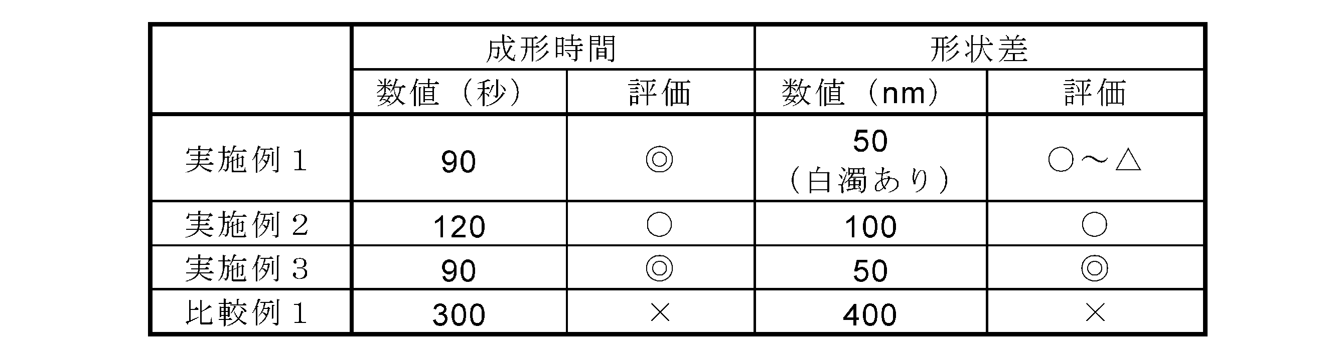
表2に示されるように、オキセタン化合物を配合した光硬化性樹脂材料を使用した実施例1~3のウエハレンズは、1回あたりの成形時間が2分以内と短く、かつレンズ部の形状差も約100nm以下と小さかった。これに対し、オキセタン化合物を配合していない光硬化性樹脂材料を使用した比較例1のウエハレンズは、1回あたりの成形時間が5分と長く、かつレンズ部の形状差も約400nmと大きかった。なお、比較例1において、室温エージングを100時間とした以外は同じ条件で形状差を測定したところ、形状差はおよそ200nmまで緩和されたものの、実使用に適さないレベルであることが確認された。
本出願は、2011年6月7日出願の特願2011-127212に基づく優先権を主張する。当該出願明細書および図面に記載された内容は、すべて本願明細書に援用される。
本発明の複合体の製造方法および複合体は、例えばウエハレンズの製造やウエハレンズ製造用の成形型の製造などにおいて有用である。
100 基板
110 樹脂成形物
120 成形部
200 成形型
210 光硬化性樹脂材料
220 光
110 樹脂成形物
120 成形部
200 成形型
210 光硬化性樹脂材料
220 光
Claims (10)
- 基板の少なくとも一方の面上に複数の樹脂成形物が形成された複合体の製造方法であって、
少なくとも一方が光透過性の基板および成形型の間に、主成分としてのエポキシ化合物と副成分としてのオキセタン化合物とを含む重合性組成物および光カチオン重合開始剤からなる光硬化性樹脂材料を介在させ、前記基板および成形型のうち少なくとも一方を介して光を照射して前記光硬化性樹脂材料を硬化させ、前記成形型を離型して前記光硬化性樹脂材料の硬化物からなる樹脂成形物を得る工程を、前記基板上の前記成形型の対向位置を変えて繰り返すことにより、前記光硬化性樹脂材料の硬化物からなる複数の樹脂成形物を形成する第1の工程と、
前記第1の工程の後に、前記複数の樹脂成形物を形成された基板を、15~30℃の温度で、低湿環境下において前記第1の工程に掛かった時間の0.5倍以上の時間放置する第2の工程と、
前記第2の工程の後に、前記複数の樹脂成形物を形成された基板を、低酸素環境下において50~200℃で加熱する第3の工程と、
を有する、複合体の製造方法。 - 前記光硬化性樹脂材料は、前記エポキシ化合物を45~95質量%、前記オキセタン化合物を1~45質量%、前記光カチオン重合開始剤を0.01~10質量%含み、
前記エポキシ化合物の含有量は、前記オキセタン化合物の含有量よりも多い、
請求項1に記載の複合体の製造方法。 - 前記光硬化性樹脂材料は、前記オキセタン化合物として、単官能オキセタン化合物および多官能オキセタン化合物を含む、請求項1または請求項2に記載の複合体の製造方法。
- 前記単官能オキセタン化合物は、3-エチル-3-ヒドロキシメチルオキセタン、3-エチル-3-(フェノキシメチル)オキセタン、3-エチル-3-(2-エチルヘキシロキシメチル)オキセタンまたはこれらの組み合わせであり、
前記多官能オキセタン化合物は、ジ[1-エチル(3-オキセタニル)]メチルエーテル、1,4ビス{[(3-エチルオキセタン-3-イル)メトキシ]メチル}オキセタンまたはこれらの組み合わせである、
請求項3に記載の複合体の製造方法。 - 前記光硬化性樹脂材料は、前記単官能オキセタン化合物を5~40質量%、前記多官能オキセタン化合物を5~40質量%含む、請求項3または4に記載の複合体の製造方法。
- 前記光硬化性樹脂材料は、さらにフッ素系界面活性剤を含む、請求項1~5のいずれか一項に記載の複合体の製造方法。
- 前記複合体は、ウエハレンズである、請求項1~6のいずれか一項に記載の複合体の製造方法。
- 前記複合体は、ウエハレンズ製造用の成形型である、請求項1~6のいずれか一項に記載の複合体の製造方法。
- 請求項1~6のいずれか一項に記載の複合体の製造方法によって得られた複合体であって、前記複数の樹脂成形物が、それぞれレンズ部であることを特徴とする、複合体。
- 請求項1~6のいずれか一項に記載の複合体の製造方法によって得られた複合体であって、前記複数の樹脂成形物が、それぞれレンズ部を成形するための成形型の光学転写面を有することを特徴とする、複合体。
Applications Claiming Priority (2)
| Application Number | Priority Date | Filing Date | Title |
|---|---|---|---|
| JP2011127212 | 2011-06-07 | ||
| JP2011-127212 | 2011-06-07 |
Publications (1)
| Publication Number | Publication Date |
|---|---|
| WO2012169120A1 true WO2012169120A1 (ja) | 2012-12-13 |
Family
ID=47295713
Family Applications (1)
| Application Number | Title | Priority Date | Filing Date |
|---|---|---|---|
| PCT/JP2012/003155 Ceased WO2012169120A1 (ja) | 2011-06-07 | 2012-05-15 | 複合体の製造方法および複合体 |
Country Status (1)
| Country | Link |
|---|---|
| WO (1) | WO2012169120A1 (ja) |
Cited By (2)
| Publication number | Priority date | Publication date | Assignee | Title |
|---|---|---|---|---|
| KR20160091333A (ko) * | 2013-11-29 | 2016-08-02 | 에베 그룹 에. 탈너 게엠베하 | 구조물을 엠보싱하기 위한 방법 및 장치 |
| KR20210010279A (ko) * | 2019-07-19 | 2021-01-27 | 주식회사 제이마이크로 | 미세 금속 마스크를 제작하는 방법 |
Citations (4)
| Publication number | Priority date | Publication date | Assignee | Title |
|---|---|---|---|---|
| JPH10119061A (ja) * | 1996-10-21 | 1998-05-12 | Ricoh Co Ltd | 精密成形方法および装置 |
| JP2003094445A (ja) * | 2001-09-20 | 2003-04-03 | Seiko Epson Corp | 微細構造体の製造方法、該微細構造体を備えた装置の製造方法、該製造方法による微細構造体、該微細構造体製造用装置並びに該微細構造体を備えた装置製造用装置 |
| WO2009125677A1 (ja) * | 2008-04-08 | 2009-10-15 | コニカミノルタオプト株式会社 | ウエハレンズの製造方法及びウエハレンズ |
| JP2010105357A (ja) * | 2008-10-31 | 2010-05-13 | Konica Minolta Opto Inc | 成形装置、成形型部材、ウエハレンズ及びウエハレンズ用成形型の製造方法 |
-
2012
- 2012-05-15 WO PCT/JP2012/003155 patent/WO2012169120A1/ja not_active Ceased
Patent Citations (4)
| Publication number | Priority date | Publication date | Assignee | Title |
|---|---|---|---|---|
| JPH10119061A (ja) * | 1996-10-21 | 1998-05-12 | Ricoh Co Ltd | 精密成形方法および装置 |
| JP2003094445A (ja) * | 2001-09-20 | 2003-04-03 | Seiko Epson Corp | 微細構造体の製造方法、該微細構造体を備えた装置の製造方法、該製造方法による微細構造体、該微細構造体製造用装置並びに該微細構造体を備えた装置製造用装置 |
| WO2009125677A1 (ja) * | 2008-04-08 | 2009-10-15 | コニカミノルタオプト株式会社 | ウエハレンズの製造方法及びウエハレンズ |
| JP2010105357A (ja) * | 2008-10-31 | 2010-05-13 | Konica Minolta Opto Inc | 成形装置、成形型部材、ウエハレンズ及びウエハレンズ用成形型の製造方法 |
Cited By (7)
| Publication number | Priority date | Publication date | Assignee | Title |
|---|---|---|---|---|
| KR20160091333A (ko) * | 2013-11-29 | 2016-08-02 | 에베 그룹 에. 탈너 게엠베하 | 구조물을 엠보싱하기 위한 방법 및 장치 |
| JP2017500738A (ja) * | 2013-11-29 | 2017-01-05 | エーファウ・グループ・エー・タルナー・ゲーエムベーハー | 構造体を型押しする方法および装置 |
| KR102250979B1 (ko) | 2013-11-29 | 2021-05-12 | 에베 그룹 에. 탈너 게엠베하 | 구조물을 엠보싱하기 위한 방법 및 장치 |
| KR20210054597A (ko) * | 2013-11-29 | 2021-05-13 | 에베 그룹 에. 탈너 게엠베하 | 구조물을 엠보싱하기 위한 방법 및 장치 |
| KR102361175B1 (ko) | 2013-11-29 | 2022-02-10 | 에베 그룹 에. 탈너 게엠베하 | 구조물을 엠보싱하기 위한 방법 및 장치 |
| KR20210010279A (ko) * | 2019-07-19 | 2021-01-27 | 주식회사 제이마이크로 | 미세 금속 마스크를 제작하는 방법 |
| KR102237716B1 (ko) | 2019-07-19 | 2021-04-08 | 한국과학기술원 | 미세 금속 마스크를 제작하는 방법 |
Similar Documents
| Publication | Publication Date | Title |
|---|---|---|
| JP5555025B2 (ja) | 微細パターン転写用スタンパ及びその製造方法 | |
| CN101776846B (zh) | 激光造型专用光固化组合物 | |
| US20150298365A1 (en) | Method for producing microstructure and photocurable composition for nanoimprinting | |
| JP5235155B2 (ja) | 微細樹脂構造体及び光電回路基板の製造方法、微細樹脂構造体及び光電回路基板 | |
| CN110945039B (zh) | 光固化性组合物及三维物体的制造方法 | |
| JP2010265360A (ja) | 光学部品用樹脂組成物およびそれを用いた光学部品 | |
| JP2014224205A (ja) | 光学部品用光硬化型樹脂組成物およびそれを用いた光学部品、並びに光学部品の製法 | |
| JPWO2009116448A1 (ja) | 成形体及びウエハレンズの製造方法 | |
| TW201529704A (zh) | 光學立體造形用光硬化性組成物、及立體造形物之製造方法 | |
| JP6348702B2 (ja) | 光学的立体造形用樹脂組成物 | |
| WO2012169120A1 (ja) | 複合体の製造方法および複合体 | |
| WO2017073370A1 (ja) | フィルムモールド及びインプリント方法 | |
| JP5415370B2 (ja) | 光硬化型樹脂組成物およびそれを用いた光学部品 | |
| JP5184336B2 (ja) | 紫外線硬化型樹脂組成物およびそれを用いて得られる光学レンズ | |
| WO2012160769A1 (ja) | 樹脂成形品の製造方法 | |
| JP7635714B2 (ja) | 紫外線硬化性樹脂組成物、硬化物及び光学レンズ | |
| JP6938189B2 (ja) | 樹脂成型品の製造方法及び光学部品の製造方法 | |
| JP2015194546A (ja) | 光学部品用樹脂組成物およびそれを用いた光学部品 | |
| JP4725280B2 (ja) | 微細形状の成形方法 | |
| KR102373393B1 (ko) | 서지컬 가이드용 광경화성 수지 조성물, 이로부터 제조된 서지컬 가이드 및 그의 제조방법 | |
| JP6957177B2 (ja) | 樹脂成型品の製造方法及び光学部品の製造方法 | |
| JP6867208B2 (ja) | 樹脂成型品の製造方法及び光学部品の製造方法 | |
| JP6938187B2 (ja) | シリコーンモールド | |
| JP6871036B2 (ja) | 樹脂成型品の製造方法及び光学部品の製造方法 | |
| JP6938191B2 (ja) | 樹脂成型品の製造方法及び光学部品の製造方法 |
Legal Events
| Date | Code | Title | Description |
|---|---|---|---|
| 121 | Ep: the epo has been informed by wipo that ep was designated in this application |
Ref document number: 12796976 Country of ref document: EP Kind code of ref document: A1 |
|
| NENP | Non-entry into the national phase |
Ref country code: DE |
|
| 122 | Ep: pct application non-entry in european phase |
Ref document number: 12796976 Country of ref document: EP Kind code of ref document: A1 |
|
| NENP | Non-entry into the national phase |
Ref country code: JP |