WO2012169086A1 - Système de charge - Google Patents
Système de charge Download PDFInfo
- Publication number
- WO2012169086A1 WO2012169086A1 PCT/JP2011/072868 JP2011072868W WO2012169086A1 WO 2012169086 A1 WO2012169086 A1 WO 2012169086A1 JP 2011072868 W JP2011072868 W JP 2011072868W WO 2012169086 A1 WO2012169086 A1 WO 2012169086A1
- Authority
- WO
- WIPO (PCT)
- Prior art keywords
- ebs
- load
- power
- vehicle
- storage
- Prior art date
Links
- 238000012360 testing method Methods 0.000 claims abstract description 58
- 238000005265 energy consumption Methods 0.000 abstract description 2
- 210000000352 storage cell Anatomy 0.000 abstract 3
- 230000005540 biological transmission Effects 0.000 description 7
- 238000010586 diagram Methods 0.000 description 5
- 239000000446 fuel Substances 0.000 description 5
- 230000018199 S phase Effects 0.000 description 4
- 238000001816 cooling Methods 0.000 description 4
- 229910001219 R-phase Inorganic materials 0.000 description 3
- 238000009434 installation Methods 0.000 description 3
- 238000010248 power generation Methods 0.000 description 3
- 230000000737 periodic effect Effects 0.000 description 2
- WHXSMMKQMYFTQS-UHFFFAOYSA-N Lithium Chemical compound [Li] WHXSMMKQMYFTQS-UHFFFAOYSA-N 0.000 description 1
- HBBGRARXTFLTSG-UHFFFAOYSA-N Lithium ion Chemical compound [Li+] HBBGRARXTFLTSG-UHFFFAOYSA-N 0.000 description 1
- OJIJEKBXJYRIBZ-UHFFFAOYSA-N cadmium nickel Chemical compound [Ni].[Cd] OJIJEKBXJYRIBZ-UHFFFAOYSA-N 0.000 description 1
- 230000003111 delayed effect Effects 0.000 description 1
- 229910052744 lithium Inorganic materials 0.000 description 1
- 229910001416 lithium ion Inorganic materials 0.000 description 1
- 238000000034 method Methods 0.000 description 1
- 229920000642 polymer Polymers 0.000 description 1
- 238000010998 test method Methods 0.000 description 1
Images


Classifications
-
- B—PERFORMING OPERATIONS; TRANSPORTING
- B60—VEHICLES IN GENERAL
- B60L—PROPULSION OF ELECTRICALLY-PROPELLED VEHICLES; SUPPLYING ELECTRIC POWER FOR AUXILIARY EQUIPMENT OF ELECTRICALLY-PROPELLED VEHICLES; ELECTRODYNAMIC BRAKE SYSTEMS FOR VEHICLES IN GENERAL; MAGNETIC SUSPENSION OR LEVITATION FOR VEHICLES; MONITORING OPERATING VARIABLES OF ELECTRICALLY-PROPELLED VEHICLES; ELECTRIC SAFETY DEVICES FOR ELECTRICALLY-PROPELLED VEHICLES
- B60L53/00—Methods of charging batteries, specially adapted for electric vehicles; Charging stations or on-board charging equipment therefor; Exchange of energy storage elements in electric vehicles
- B60L53/10—Methods of charging batteries, specially adapted for electric vehicles; Charging stations or on-board charging equipment therefor; Exchange of energy storage elements in electric vehicles characterised by the energy transfer between the charging station and the vehicle
- B60L53/14—Conductive energy transfer
-
- B—PERFORMING OPERATIONS; TRANSPORTING
- B60—VEHICLES IN GENERAL
- B60L—PROPULSION OF ELECTRICALLY-PROPELLED VEHICLES; SUPPLYING ELECTRIC POWER FOR AUXILIARY EQUIPMENT OF ELECTRICALLY-PROPELLED VEHICLES; ELECTRODYNAMIC BRAKE SYSTEMS FOR VEHICLES IN GENERAL; MAGNETIC SUSPENSION OR LEVITATION FOR VEHICLES; MONITORING OPERATING VARIABLES OF ELECTRICALLY-PROPELLED VEHICLES; ELECTRIC SAFETY DEVICES FOR ELECTRICALLY-PROPELLED VEHICLES
- B60L1/00—Supplying electric power to auxiliary equipment of vehicles
- B60L1/003—Supplying electric power to auxiliary equipment of vehicles to auxiliary motors, e.g. for pumps, compressors
-
- B—PERFORMING OPERATIONS; TRANSPORTING
- B60—VEHICLES IN GENERAL
- B60L—PROPULSION OF ELECTRICALLY-PROPELLED VEHICLES; SUPPLYING ELECTRIC POWER FOR AUXILIARY EQUIPMENT OF ELECTRICALLY-PROPELLED VEHICLES; ELECTRODYNAMIC BRAKE SYSTEMS FOR VEHICLES IN GENERAL; MAGNETIC SUSPENSION OR LEVITATION FOR VEHICLES; MONITORING OPERATING VARIABLES OF ELECTRICALLY-PROPELLED VEHICLES; ELECTRIC SAFETY DEVICES FOR ELECTRICALLY-PROPELLED VEHICLES
- B60L50/00—Electric propulsion with power supplied within the vehicle
- B60L50/10—Electric propulsion with power supplied within the vehicle using propulsion power supplied by engine-driven generators, e.g. generators driven by combustion engines
- B60L50/16—Electric propulsion with power supplied within the vehicle using propulsion power supplied by engine-driven generators, e.g. generators driven by combustion engines with provision for separate direct mechanical propulsion
-
- B—PERFORMING OPERATIONS; TRANSPORTING
- B60—VEHICLES IN GENERAL
- B60L—PROPULSION OF ELECTRICALLY-PROPELLED VEHICLES; SUPPLYING ELECTRIC POWER FOR AUXILIARY EQUIPMENT OF ELECTRICALLY-PROPELLED VEHICLES; ELECTRODYNAMIC BRAKE SYSTEMS FOR VEHICLES IN GENERAL; MAGNETIC SUSPENSION OR LEVITATION FOR VEHICLES; MONITORING OPERATING VARIABLES OF ELECTRICALLY-PROPELLED VEHICLES; ELECTRIC SAFETY DEVICES FOR ELECTRICALLY-PROPELLED VEHICLES
- B60L50/00—Electric propulsion with power supplied within the vehicle
- B60L50/50—Electric propulsion with power supplied within the vehicle using propulsion power supplied by batteries or fuel cells
- B60L50/60—Electric propulsion with power supplied within the vehicle using propulsion power supplied by batteries or fuel cells using power supplied by batteries
- B60L50/66—Arrangements of batteries
-
- B—PERFORMING OPERATIONS; TRANSPORTING
- B60—VEHICLES IN GENERAL
- B60L—PROPULSION OF ELECTRICALLY-PROPELLED VEHICLES; SUPPLYING ELECTRIC POWER FOR AUXILIARY EQUIPMENT OF ELECTRICALLY-PROPELLED VEHICLES; ELECTRODYNAMIC BRAKE SYSTEMS FOR VEHICLES IN GENERAL; MAGNETIC SUSPENSION OR LEVITATION FOR VEHICLES; MONITORING OPERATING VARIABLES OF ELECTRICALLY-PROPELLED VEHICLES; ELECTRIC SAFETY DEVICES FOR ELECTRICALLY-PROPELLED VEHICLES
- B60L53/00—Methods of charging batteries, specially adapted for electric vehicles; Charging stations or on-board charging equipment therefor; Exchange of energy storage elements in electric vehicles
- B60L53/10—Methods of charging batteries, specially adapted for electric vehicles; Charging stations or on-board charging equipment therefor; Exchange of energy storage elements in electric vehicles characterised by the energy transfer between the charging station and the vehicle
- B60L53/11—DC charging controlled by the charging station, e.g. mode 4
-
- B—PERFORMING OPERATIONS; TRANSPORTING
- B60—VEHICLES IN GENERAL
- B60L—PROPULSION OF ELECTRICALLY-PROPELLED VEHICLES; SUPPLYING ELECTRIC POWER FOR AUXILIARY EQUIPMENT OF ELECTRICALLY-PROPELLED VEHICLES; ELECTRODYNAMIC BRAKE SYSTEMS FOR VEHICLES IN GENERAL; MAGNETIC SUSPENSION OR LEVITATION FOR VEHICLES; MONITORING OPERATING VARIABLES OF ELECTRICALLY-PROPELLED VEHICLES; ELECTRIC SAFETY DEVICES FOR ELECTRICALLY-PROPELLED VEHICLES
- B60L53/00—Methods of charging batteries, specially adapted for electric vehicles; Charging stations or on-board charging equipment therefor; Exchange of energy storage elements in electric vehicles
- B60L53/50—Charging stations characterised by energy-storage or power-generation means
- B60L53/51—Photovoltaic means
-
- B—PERFORMING OPERATIONS; TRANSPORTING
- B60—VEHICLES IN GENERAL
- B60L—PROPULSION OF ELECTRICALLY-PROPELLED VEHICLES; SUPPLYING ELECTRIC POWER FOR AUXILIARY EQUIPMENT OF ELECTRICALLY-PROPELLED VEHICLES; ELECTRODYNAMIC BRAKE SYSTEMS FOR VEHICLES IN GENERAL; MAGNETIC SUSPENSION OR LEVITATION FOR VEHICLES; MONITORING OPERATING VARIABLES OF ELECTRICALLY-PROPELLED VEHICLES; ELECTRIC SAFETY DEVICES FOR ELECTRICALLY-PROPELLED VEHICLES
- B60L53/00—Methods of charging batteries, specially adapted for electric vehicles; Charging stations or on-board charging equipment therefor; Exchange of energy storage elements in electric vehicles
- B60L53/50—Charging stations characterised by energy-storage or power-generation means
- B60L53/52—Wind-driven generators
-
- B—PERFORMING OPERATIONS; TRANSPORTING
- B60—VEHICLES IN GENERAL
- B60L—PROPULSION OF ELECTRICALLY-PROPELLED VEHICLES; SUPPLYING ELECTRIC POWER FOR AUXILIARY EQUIPMENT OF ELECTRICALLY-PROPELLED VEHICLES; ELECTRODYNAMIC BRAKE SYSTEMS FOR VEHICLES IN GENERAL; MAGNETIC SUSPENSION OR LEVITATION FOR VEHICLES; MONITORING OPERATING VARIABLES OF ELECTRICALLY-PROPELLED VEHICLES; ELECTRIC SAFETY DEVICES FOR ELECTRICALLY-PROPELLED VEHICLES
- B60L53/00—Methods of charging batteries, specially adapted for electric vehicles; Charging stations or on-board charging equipment therefor; Exchange of energy storage elements in electric vehicles
- B60L53/60—Monitoring or controlling charging stations
- B60L53/65—Monitoring or controlling charging stations involving identification of vehicles or their battery types
-
- B—PERFORMING OPERATIONS; TRANSPORTING
- B60—VEHICLES IN GENERAL
- B60L—PROPULSION OF ELECTRICALLY-PROPELLED VEHICLES; SUPPLYING ELECTRIC POWER FOR AUXILIARY EQUIPMENT OF ELECTRICALLY-PROPELLED VEHICLES; ELECTRODYNAMIC BRAKE SYSTEMS FOR VEHICLES IN GENERAL; MAGNETIC SUSPENSION OR LEVITATION FOR VEHICLES; MONITORING OPERATING VARIABLES OF ELECTRICALLY-PROPELLED VEHICLES; ELECTRIC SAFETY DEVICES FOR ELECTRICALLY-PROPELLED VEHICLES
- B60L58/00—Methods or circuit arrangements for monitoring or controlling batteries or fuel cells, specially adapted for electric vehicles
- B60L58/10—Methods or circuit arrangements for monitoring or controlling batteries or fuel cells, specially adapted for electric vehicles for monitoring or controlling batteries
- B60L58/18—Methods or circuit arrangements for monitoring or controlling batteries or fuel cells, specially adapted for electric vehicles for monitoring or controlling batteries of two or more battery modules
- B60L58/21—Methods or circuit arrangements for monitoring or controlling batteries or fuel cells, specially adapted for electric vehicles for monitoring or controlling batteries of two or more battery modules having the same nominal voltage
-
- B—PERFORMING OPERATIONS; TRANSPORTING
- B60—VEHICLES IN GENERAL
- B60L—PROPULSION OF ELECTRICALLY-PROPELLED VEHICLES; SUPPLYING ELECTRIC POWER FOR AUXILIARY EQUIPMENT OF ELECTRICALLY-PROPELLED VEHICLES; ELECTRODYNAMIC BRAKE SYSTEMS FOR VEHICLES IN GENERAL; MAGNETIC SUSPENSION OR LEVITATION FOR VEHICLES; MONITORING OPERATING VARIABLES OF ELECTRICALLY-PROPELLED VEHICLES; ELECTRIC SAFETY DEVICES FOR ELECTRICALLY-PROPELLED VEHICLES
- B60L58/00—Methods or circuit arrangements for monitoring or controlling batteries or fuel cells, specially adapted for electric vehicles
- B60L58/10—Methods or circuit arrangements for monitoring or controlling batteries or fuel cells, specially adapted for electric vehicles for monitoring or controlling batteries
- B60L58/24—Methods or circuit arrangements for monitoring or controlling batteries or fuel cells, specially adapted for electric vehicles for monitoring or controlling batteries for controlling the temperature of batteries
- B60L58/26—Methods or circuit arrangements for monitoring or controlling batteries or fuel cells, specially adapted for electric vehicles for monitoring or controlling batteries for controlling the temperature of batteries by cooling
-
- G—PHYSICS
- G01—MEASURING; TESTING
- G01R—MEASURING ELECTRIC VARIABLES; MEASURING MAGNETIC VARIABLES
- G01R31/00—Arrangements for testing electric properties; Arrangements for locating electric faults; Arrangements for electrical testing characterised by what is being tested not provided for elsewhere
- G01R31/36—Arrangements for testing, measuring or monitoring the electrical condition of accumulators or electric batteries, e.g. capacity or state of charge [SoC]
- G01R31/385—Arrangements for measuring battery or accumulator variables
- G01R31/386—Arrangements for measuring battery or accumulator variables using test-loads
-
- H—ELECTRICITY
- H02—GENERATION; CONVERSION OR DISTRIBUTION OF ELECTRIC POWER
- H02J—CIRCUIT ARRANGEMENTS OR SYSTEMS FOR SUPPLYING OR DISTRIBUTING ELECTRIC POWER; SYSTEMS FOR STORING ELECTRIC ENERGY
- H02J7/00—Circuit arrangements for charging or depolarising batteries or for supplying loads from batteries
- H02J7/0013—Circuit arrangements for charging or depolarising batteries or for supplying loads from batteries acting upon several batteries simultaneously or sequentially
- H02J7/0024—Parallel/serial switching of connection of batteries to charge or load circuit
-
- H—ELECTRICITY
- H02—GENERATION; CONVERSION OR DISTRIBUTION OF ELECTRIC POWER
- H02S—GENERATION OF ELECTRIC POWER BY CONVERSION OF INFRARED RADIATION, VISIBLE LIGHT OR ULTRAVIOLET LIGHT, e.g. USING PHOTOVOLTAIC [PV] MODULES
- H02S50/00—Monitoring or testing of PV systems, e.g. load balancing or fault identification
- H02S50/10—Testing of PV devices, e.g. of PV modules or single PV cells
-
- B—PERFORMING OPERATIONS; TRANSPORTING
- B60—VEHICLES IN GENERAL
- B60L—PROPULSION OF ELECTRICALLY-PROPELLED VEHICLES; SUPPLYING ELECTRIC POWER FOR AUXILIARY EQUIPMENT OF ELECTRICALLY-PROPELLED VEHICLES; ELECTRODYNAMIC BRAKE SYSTEMS FOR VEHICLES IN GENERAL; MAGNETIC SUSPENSION OR LEVITATION FOR VEHICLES; MONITORING OPERATING VARIABLES OF ELECTRICALLY-PROPELLED VEHICLES; ELECTRIC SAFETY DEVICES FOR ELECTRICALLY-PROPELLED VEHICLES
- B60L2200/00—Type of vehicles
- B60L2200/26—Rail vehicles
-
- B—PERFORMING OPERATIONS; TRANSPORTING
- B60—VEHICLES IN GENERAL
- B60L—PROPULSION OF ELECTRICALLY-PROPELLED VEHICLES; SUPPLYING ELECTRIC POWER FOR AUXILIARY EQUIPMENT OF ELECTRICALLY-PROPELLED VEHICLES; ELECTRODYNAMIC BRAKE SYSTEMS FOR VEHICLES IN GENERAL; MAGNETIC SUSPENSION OR LEVITATION FOR VEHICLES; MONITORING OPERATING VARIABLES OF ELECTRICALLY-PROPELLED VEHICLES; ELECTRIC SAFETY DEVICES FOR ELECTRICALLY-PROPELLED VEHICLES
- B60L2200/00—Type of vehicles
- B60L2200/36—Vehicles designed to transport cargo, e.g. trucks
-
- B—PERFORMING OPERATIONS; TRANSPORTING
- B60—VEHICLES IN GENERAL
- B60L—PROPULSION OF ELECTRICALLY-PROPELLED VEHICLES; SUPPLYING ELECTRIC POWER FOR AUXILIARY EQUIPMENT OF ELECTRICALLY-PROPELLED VEHICLES; ELECTRODYNAMIC BRAKE SYSTEMS FOR VEHICLES IN GENERAL; MAGNETIC SUSPENSION OR LEVITATION FOR VEHICLES; MONITORING OPERATING VARIABLES OF ELECTRICALLY-PROPELLED VEHICLES; ELECTRIC SAFETY DEVICES FOR ELECTRICALLY-PROPELLED VEHICLES
- B60L2210/00—Converter types
- B60L2210/40—DC to AC converters
-
- B—PERFORMING OPERATIONS; TRANSPORTING
- B60—VEHICLES IN GENERAL
- B60L—PROPULSION OF ELECTRICALLY-PROPELLED VEHICLES; SUPPLYING ELECTRIC POWER FOR AUXILIARY EQUIPMENT OF ELECTRICALLY-PROPELLED VEHICLES; ELECTRODYNAMIC BRAKE SYSTEMS FOR VEHICLES IN GENERAL; MAGNETIC SUSPENSION OR LEVITATION FOR VEHICLES; MONITORING OPERATING VARIABLES OF ELECTRICALLY-PROPELLED VEHICLES; ELECTRIC SAFETY DEVICES FOR ELECTRICALLY-PROPELLED VEHICLES
- B60L2220/00—Electrical machine types; Structures or applications thereof
- B60L2220/40—Electrical machine applications
- B60L2220/44—Wheel Hub motors, i.e. integrated in the wheel hub
-
- B—PERFORMING OPERATIONS; TRANSPORTING
- B60—VEHICLES IN GENERAL
- B60L—PROPULSION OF ELECTRICALLY-PROPELLED VEHICLES; SUPPLYING ELECTRIC POWER FOR AUXILIARY EQUIPMENT OF ELECTRICALLY-PROPELLED VEHICLES; ELECTRODYNAMIC BRAKE SYSTEMS FOR VEHICLES IN GENERAL; MAGNETIC SUSPENSION OR LEVITATION FOR VEHICLES; MONITORING OPERATING VARIABLES OF ELECTRICALLY-PROPELLED VEHICLES; ELECTRIC SAFETY DEVICES FOR ELECTRICALLY-PROPELLED VEHICLES
- B60L2240/00—Control parameters of input or output; Target parameters
- B60L2240/70—Interactions with external data bases, e.g. traffic centres
-
- B—PERFORMING OPERATIONS; TRANSPORTING
- B60—VEHICLES IN GENERAL
- B60L—PROPULSION OF ELECTRICALLY-PROPELLED VEHICLES; SUPPLYING ELECTRIC POWER FOR AUXILIARY EQUIPMENT OF ELECTRICALLY-PROPELLED VEHICLES; ELECTRODYNAMIC BRAKE SYSTEMS FOR VEHICLES IN GENERAL; MAGNETIC SUSPENSION OR LEVITATION FOR VEHICLES; MONITORING OPERATING VARIABLES OF ELECTRICALLY-PROPELLED VEHICLES; ELECTRIC SAFETY DEVICES FOR ELECTRICALLY-PROPELLED VEHICLES
- B60L2260/00—Operating Modes
- B60L2260/20—Drive modes; Transition between modes
- B60L2260/28—Four wheel or all wheel drive
-
- G—PHYSICS
- G01—MEASURING; TESTING
- G01R—MEASURING ELECTRIC VARIABLES; MEASURING MAGNETIC VARIABLES
- G01R31/00—Arrangements for testing electric properties; Arrangements for locating electric faults; Arrangements for electrical testing characterised by what is being tested not provided for elsewhere
- G01R31/40—Testing power supplies
-
- Y—GENERAL TAGGING OF NEW TECHNOLOGICAL DEVELOPMENTS; GENERAL TAGGING OF CROSS-SECTIONAL TECHNOLOGIES SPANNING OVER SEVERAL SECTIONS OF THE IPC; TECHNICAL SUBJECTS COVERED BY FORMER USPC CROSS-REFERENCE ART COLLECTIONS [XRACs] AND DIGESTS
- Y02—TECHNOLOGIES OR APPLICATIONS FOR MITIGATION OR ADAPTATION AGAINST CLIMATE CHANGE
- Y02E—REDUCTION OF GREENHOUSE GAS [GHG] EMISSIONS, RELATED TO ENERGY GENERATION, TRANSMISSION OR DISTRIBUTION
- Y02E10/00—Energy generation through renewable energy sources
- Y02E10/50—Photovoltaic [PV] energy
-
- Y—GENERAL TAGGING OF NEW TECHNOLOGICAL DEVELOPMENTS; GENERAL TAGGING OF CROSS-SECTIONAL TECHNOLOGIES SPANNING OVER SEVERAL SECTIONS OF THE IPC; TECHNICAL SUBJECTS COVERED BY FORMER USPC CROSS-REFERENCE ART COLLECTIONS [XRACs] AND DIGESTS
- Y02—TECHNOLOGIES OR APPLICATIONS FOR MITIGATION OR ADAPTATION AGAINST CLIMATE CHANGE
- Y02T—CLIMATE CHANGE MITIGATION TECHNOLOGIES RELATED TO TRANSPORTATION
- Y02T10/00—Road transport of goods or passengers
- Y02T10/60—Other road transportation technologies with climate change mitigation effect
- Y02T10/70—Energy storage systems for electromobility, e.g. batteries
-
- Y—GENERAL TAGGING OF NEW TECHNOLOGICAL DEVELOPMENTS; GENERAL TAGGING OF CROSS-SECTIONAL TECHNOLOGIES SPANNING OVER SEVERAL SECTIONS OF THE IPC; TECHNICAL SUBJECTS COVERED BY FORMER USPC CROSS-REFERENCE ART COLLECTIONS [XRACs] AND DIGESTS
- Y02—TECHNOLOGIES OR APPLICATIONS FOR MITIGATION OR ADAPTATION AGAINST CLIMATE CHANGE
- Y02T—CLIMATE CHANGE MITIGATION TECHNOLOGIES RELATED TO TRANSPORTATION
- Y02T10/00—Road transport of goods or passengers
- Y02T10/60—Other road transportation technologies with climate change mitigation effect
- Y02T10/7072—Electromobility specific charging systems or methods for batteries, ultracapacitors, supercapacitors or double-layer capacitors
-
- Y—GENERAL TAGGING OF NEW TECHNOLOGICAL DEVELOPMENTS; GENERAL TAGGING OF CROSS-SECTIONAL TECHNOLOGIES SPANNING OVER SEVERAL SECTIONS OF THE IPC; TECHNICAL SUBJECTS COVERED BY FORMER USPC CROSS-REFERENCE ART COLLECTIONS [XRACs] AND DIGESTS
- Y02—TECHNOLOGIES OR APPLICATIONS FOR MITIGATION OR ADAPTATION AGAINST CLIMATE CHANGE
- Y02T—CLIMATE CHANGE MITIGATION TECHNOLOGIES RELATED TO TRANSPORTATION
- Y02T10/00—Road transport of goods or passengers
- Y02T10/60—Other road transportation technologies with climate change mitigation effect
- Y02T10/72—Electric energy management in electromobility
-
- Y—GENERAL TAGGING OF NEW TECHNOLOGICAL DEVELOPMENTS; GENERAL TAGGING OF CROSS-SECTIONAL TECHNOLOGIES SPANNING OVER SEVERAL SECTIONS OF THE IPC; TECHNICAL SUBJECTS COVERED BY FORMER USPC CROSS-REFERENCE ART COLLECTIONS [XRACs] AND DIGESTS
- Y02—TECHNOLOGIES OR APPLICATIONS FOR MITIGATION OR ADAPTATION AGAINST CLIMATE CHANGE
- Y02T—CLIMATE CHANGE MITIGATION TECHNOLOGIES RELATED TO TRANSPORTATION
- Y02T10/00—Road transport of goods or passengers
- Y02T10/80—Technologies aiming to reduce greenhouse gasses emissions common to all road transportation technologies
- Y02T10/92—Energy efficient charging or discharging systems for batteries, ultracapacitors, supercapacitors or double-layer capacitors specially adapted for vehicles
-
- Y—GENERAL TAGGING OF NEW TECHNOLOGICAL DEVELOPMENTS; GENERAL TAGGING OF CROSS-SECTIONAL TECHNOLOGIES SPANNING OVER SEVERAL SECTIONS OF THE IPC; TECHNICAL SUBJECTS COVERED BY FORMER USPC CROSS-REFERENCE ART COLLECTIONS [XRACs] AND DIGESTS
- Y02—TECHNOLOGIES OR APPLICATIONS FOR MITIGATION OR ADAPTATION AGAINST CLIMATE CHANGE
- Y02T—CLIMATE CHANGE MITIGATION TECHNOLOGIES RELATED TO TRANSPORTATION
- Y02T90/00—Enabling technologies or technologies with a potential or indirect contribution to GHG emissions mitigation
- Y02T90/10—Technologies relating to charging of electric vehicles
- Y02T90/12—Electric charging stations
-
- Y—GENERAL TAGGING OF NEW TECHNOLOGICAL DEVELOPMENTS; GENERAL TAGGING OF CROSS-SECTIONAL TECHNOLOGIES SPANNING OVER SEVERAL SECTIONS OF THE IPC; TECHNICAL SUBJECTS COVERED BY FORMER USPC CROSS-REFERENCE ART COLLECTIONS [XRACs] AND DIGESTS
- Y02—TECHNOLOGIES OR APPLICATIONS FOR MITIGATION OR ADAPTATION AGAINST CLIMATE CHANGE
- Y02T—CLIMATE CHANGE MITIGATION TECHNOLOGIES RELATED TO TRANSPORTATION
- Y02T90/00—Enabling technologies or technologies with a potential or indirect contribution to GHG emissions mitigation
- Y02T90/10—Technologies relating to charging of electric vehicles
- Y02T90/14—Plug-in electric vehicles
-
- Y—GENERAL TAGGING OF NEW TECHNOLOGICAL DEVELOPMENTS; GENERAL TAGGING OF CROSS-SECTIONAL TECHNOLOGIES SPANNING OVER SEVERAL SECTIONS OF THE IPC; TECHNICAL SUBJECTS COVERED BY FORMER USPC CROSS-REFERENCE ART COLLECTIONS [XRACs] AND DIGESTS
- Y02—TECHNOLOGIES OR APPLICATIONS FOR MITIGATION OR ADAPTATION AGAINST CLIMATE CHANGE
- Y02T—CLIMATE CHANGE MITIGATION TECHNOLOGIES RELATED TO TRANSPORTATION
- Y02T90/00—Enabling technologies or technologies with a potential or indirect contribution to GHG emissions mitigation
- Y02T90/10—Technologies relating to charging of electric vehicles
- Y02T90/16—Information or communication technologies improving the operation of electric vehicles
- Y02T90/167—Systems integrating technologies related to power network operation and communication or information technologies for supporting the interoperability of electric or hybrid vehicles, i.e. smartgrids as interface for battery charging of electric vehicles [EV] or hybrid vehicles [HEV]
-
- Y—GENERAL TAGGING OF NEW TECHNOLOGICAL DEVELOPMENTS; GENERAL TAGGING OF CROSS-SECTIONAL TECHNOLOGIES SPANNING OVER SEVERAL SECTIONS OF THE IPC; TECHNICAL SUBJECTS COVERED BY FORMER USPC CROSS-REFERENCE ART COLLECTIONS [XRACs] AND DIGESTS
- Y04—INFORMATION OR COMMUNICATION TECHNOLOGIES HAVING AN IMPACT ON OTHER TECHNOLOGY AREAS
- Y04S—SYSTEMS INTEGRATING TECHNOLOGIES RELATED TO POWER NETWORK OPERATION, COMMUNICATION OR INFORMATION TECHNOLOGIES FOR IMPROVING THE ELECTRICAL POWER GENERATION, TRANSMISSION, DISTRIBUTION, MANAGEMENT OR USAGE, i.e. SMART GRIDS
- Y04S30/00—Systems supporting specific end-user applications in the sector of transportation
- Y04S30/10—Systems supporting the interoperability of electric or hybrid vehicles
- Y04S30/14—Details associated with the interoperability, e.g. vehicle recognition, authentication, identification or billing
Definitions
- This invention relates to a load system having a load resistance for a load test.
- a conventional load test apparatus is known as a dry load test apparatus that performs a load test according to the output of a power source by selectively switching the connection conditions of a series connection or a parallel connection of a plurality of load resistors. (See, for example, Patent Document 1).
- an object of the present invention is to provide a load system that can reduce power energy that is wasted in a load test.
- a load system includes a power input unit for a load test of an external power source, a load having a plurality of storage batteries as a plurality of load resistors connected to the power input unit, And a control circuit for selectively switching and connecting the plurality of load resistors to the power input unit.
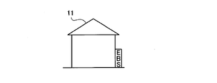
- FIG. 4 is a charging circuit diagram of the load system of FIGS. 1 to 3; It is explanatory drawing which applied the storage battery of FIG. 4 to the vehicle. It is explanatory drawing which applied the storage battery of FIG. 4 to the house.
- FIG. 2 is a side view of a vehicle in which the load system shown in FIG. 1 is mounted on the vehicle. It is a side view which shows the state which opened the door of the load system of the vehicle of FIG. It is explanatory drawing of the electric vehicle which provided the wheel driven with the storage battery of the load system of FIG. FIG.
- FIG. 10 is a charging circuit diagram of the electric vehicle in FIG. 9.
- 7 is an explanatory diagram of a hybrid vehicle provided with wheels driven by a storage battery of the load system. It is a charging circuit diagram of the hybrid vehicle of FIG. It is a top view of the vehicle which shows the other example of the load system of FIG. It is a side view of the vehicle of FIG.
- FIG. 15 is a charging circuit diagram of the vehicle in FIGS. 13 and 14. It is explanatory drawing which shows the other example of arrangement
- [Constitution] 1 to 4 show an installation type load system as an example of a load test apparatus (load system) A according to the present invention.
- F is a floor surface in a building (not shown), and B is a base disposed on the floor surface F. 1 to 4, 1 is a load storage case fixed on the base B, 2 is a load storage portion provided in the load storage case 1, and 3 is a control panel provided in the load storage case 1. .
- Doors DrR, DrS, DrT for opening and closing the load storage unit 2 are provided on the side of the load storage case 1 and the load storage unit 2 is opened as shown in FIG. 2 by opening the doors DrR, DrS, DrT. be able to.
- the doors DrR, DrS, and DrT are shown only on one side of the load storage case 1 but are also provided on the other side.
- a resistance unit 4 used as a load resistance for a load test is stored.
- This resistance unit 4 has a storage battery unit EBS (R) as the R-phase load resistance, a storage battery unit EBS (S) as the S-phase load resistance, T, so that a load test of the three-phase AC power supply can be performed.
- a storage battery unit EBS (T) as a phase load resistance is included. Since each storage battery unit EBS (R), EBS (S), EBS (T) as the load resistance has the same configuration, the storage battery units EBS (R), EBS (S), EBS (T) can be used as they are or simply.
- the storage battery unit EBS will be described.
- the storage battery unit EBS includes a plurality of storage batteries (secondary batteries) EBS (1) to EBS (i) to EBS (n), and a plurality of storage batteries (secondary batteries) EBS (1) to EBS (i) to The EBS (n) is detachably (replaceable) mounted in the load storage portion 2 of the load storage case 1.
- the storage battery unit EBS has an auxiliary storage battery (secondary battery) EBS (AX).
- a plurality of storage batteries EBS (1) to EBS (i) to EBS (n) can be detachably (replaceable) attached to the load storage unit 2, a well-known technique can be used, and detailed description thereof is omitted. To do.
- the storage batteries EBS (1) to EBS (i) to EBS (n), auxiliary storage batteries (secondary batteries) EBS (AX), etc. can be attached and detached by opening the doors DrR, DrS and DrT as shown in FIG. It carries out in the state which opened the load storage part 2.
- the storage batteries EBS (1) to EBS (i) to EBS (n) of the resistance units R, S, and T include, for example, a plurality of rod-shaped resistors described in Japanese Unexamined Patent Application Publication No. 2010-25575 (known document). Similarly, by changing the connection, the condition of the load (voltage) of the power supply is changed and used for the load test of the power supply. Since this load test method is not an essential part of the present invention, a detailed description thereof will be omitted.
- R-phase, S-phase, and T-phase storage batteries EBS (1) to EBS (i) to EBS (n) have resistances of R, S, and T phases as described in, for example, Japanese Patent Application Laid-Open No. 2010-255752.
- the power supply equipment PS such as the emergency generator, UPS (uninterruptible power supply) in FIG. 4 is switched and connected in the same manner as the plurality of resistors (resistors) of the unit (the resistance units of reference numerals 42, 43, and 44 in the publication). Used for load tests.
- a power supply facility for performing a load test there is a thermal power generator that is stopped for use in an emergency, or a nuclear power generator that is stopped.
- a wind power generator, a solar panel (solar power generation device), or the like may be used as another power supply facility for performing the load test.
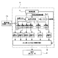
- the control panel 3 includes a power input unit 5, a quick charging circuit 6, a small-capacity charging circuit 7, and a connection switching circuit 8.
- a control circuit 9 that controls the small-capacity charging circuit 7 and the connection switching circuit 8 is provided.
- the control circuit 9 controls the operation of the connection switching circuit 8 and causes the connection switching circuit 8 to select the storage batteries EBS (1) to EBS (i) to EBS (n) to be charged by the quick charging circuit 6. Then, the connection switching circuit 8 controls to change the connection conditions of the storage batteries EBS (1) to EBS (i) to EBS (n), so that the charging voltage and the charging current by the quick charging circuit 6 are stored in the storage battery EBS (1 ) To EBS (i) to EBS (n) so as to correspond to the specifications of the charging voltage and charging current.
- the charging voltage and charging current are set to values optimum for charging the storage batteries EBS (1) to EBS (i) to EBS (n) or values close thereto.
- This setting differs depending on the type of battery used for storage batteries EBS (1) to EBS (i) to EBS (n).
- the storage batteries EBS (1) to EBS (i) to EBS (n) for example, other secondary batteries such as a lithium ion secondary battery, a nickel-cadmium storage battery, a lithium polymer secondary battery are used. Can do.
- the quick charging circuit 6 is used for quick charging of the storage batteries EBS (1) to EBS (i) to EBS (n), and the small capacity charging circuit 7 is used for charging the auxiliary storage battery EBS (AX).
- the small-capacity charging circuit 7 is used for fine adjustment of the charging voltage and charging current by the quick charging circuit 6. The fine adjustment is controlled by the control circuit 9.
- the storage batteries EBS (1) to EBS (i) to EBS (n) of the storage battery units EBS (R), EBS (S), and EBS (T) have gaps (not shown) serving as air paths in adjacent portions. ) Is provided and is air-cooled with air blown upward from the cooling fan Fa below each storage battery unit EBS (R), EBS (S), EBS (T). [Action] Next, the operation of the load test apparatus (load system) A having such a configuration will be described.
- This load test device A is used as a stationary type in a place or building where the power supply facility PS is located.
- the power supply equipment PS includes the emergency generator shown in FIG. 4, UPS (uninterruptible power supply), a thermal power generator that is stopped for emergency use, or a nuclear power generator that is stopped, and a wind power generator. And solar panels (solar power generation devices).
- UPS uninterruptible power supply
- the power supply equipment PS such as an emergency generator and UPS (uninterruptible power supply) is installed in buildings of other public facilities such as hospitals, railway facilities, airport facilities, and buildings with bank data banks.
- the load test of the power supply equipment PS is periodically performed by the load test apparatus A.
- the storage batteries EBS (1) to EBS (i) to EBS (n) of the load test apparatus A and the auxiliary storage battery EBS (AX) are connected via the quick charging circuit 6 and the small capacity charging circuit 7. It is charged with electric power supplied from a power source PS such as a power generator, a UPS (uninterruptible power supply) thermal generator, or a nuclear power generator.
- a power source PS such as a power generator, a UPS (uninterruptible power supply) thermal generator, or a nuclear power generator.
- the cooling fan Fa is activated, and the cooling air from the cooling fan Fa flows around the storage batteries EBS (1) to EBS (i) to EBS (n) and the auxiliary storage battery EBS (AX) for charging.
- the storage batteries EBS (1) to EBS (i) to EBS (n) and the auxiliary storage battery EBS (AX) that generate heat are cooled.
- the power supplied from the power supply equipment PS is simply consumed as thermal energy by the resistor, whereas the power supplied from the power supply equipment PS is used as the storage battery EBS as in this embodiment.
- EBS (i) to EBS (n) by charging and storing in the auxiliary storage battery EBS (AX), the power supplied from the power supply facility PS can be consumed without wasting it. It can be used effectively by using it as a power source for the battery EBS of the EV car (electric car) 5 or the building 11 such as the house of FIG.
- the charged storage batteries EBS (1) to EBS (i) to EBS (n) and the auxiliary storage battery EBS (AX) are set to the same standard as the battery EBS of the EV vehicle (electric vehicle) 10 shown in FIG.
- the storage batteries EBS (1) to EBS (i) to EBS (n) and the auxiliary storage battery EBS (AX) are taken out from the load storage part 2 after charging, and the taken out storage batteries EBS (1) to EBS (i)
- the EBS (n) and the auxiliary storage battery EBS (AX) can be used as the battery EBS of the EV vehicle (electric vehicle).
- the storage batteries EBS (1) to EBS (i) to EBS (n) and the auxiliary storage battery EBS (AX) are used as a power source for a building 11 such as a house as shown in FIG.
- this load test apparatus A is used as a charging apparatus when a load test is not performed.
- the emergency generator UPS (uninterruptible power supply) in FIG. 4, a thermal power generator that is stopped for use in an emergency, or a nuclear power generator that is stopped, a wind power generator or a solar panel (solar power generator) ), Etc.
- UPS uninterruptible power supply
- a thermal power generator that is stopped for use in an emergency
- a nuclear power generator that is stopped
- Etc. when supplying power to a load such as an electric device or an electronic device in a building, the surplus power remaining in the use state of the load such as the electric device or the electronic device is stored using the load test device A as a charging device.
- EBS (1) to EBS (i) to EBS (n) and the auxiliary storage battery EBS (AX) wasteful energy consumption can be prevented.
- test apparatus A may use one of R-phase, S-phase, and T-phase resistance units.
- the load test apparatus A can be always operated to charge the storage batteries EBS (1) to EBS (i) to EBS (n) and the auxiliary storage battery EBS (AX) instead of the periodic load test.
- the load test of the power supply facility PS can be constantly performed with the charging of the storage batteries EBS (1) to EBS (i) to EBS (n) and the auxiliary storage battery EBS (AX).
- the load test apparatus (load system) A is installed and used.
- the present invention is not necessarily limited thereto.
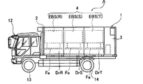
- the load test apparatus (load system) A shown in FIGS. 7 to 10 may be mounted on the vehicle 12 such as a truck and moved as shown in FIGS. .
- the vehicle 12 shown in FIG. 9 uses a truck having front wheels (wheels) 13 and rear wheels (wheels) 14 that can be driven by wheel drive motors M1 and M2.
- the vehicle 12 is an EV vehicle (electric vehicle). It has become.
- the load test apparatus A is configured such that power (electric power) supplied from the power supply facility PS is input to the load switch 15 via the power input unit 5.
- the load switch 15 is controlled by the control circuit 9 to switch the plurality of chargers (Bc1 to Bci to Bcn) and to the storage battery EBS (i) connected to the chargers (Bc1 to Bci to Bcn).
- a charging voltage and a charging current are supplied. Since the chargers (Bc1 to Bci to Bcn) can use known quick chargers, detailed description of the chargers (Bc1 to Bci to Bcn) will be omitted.
- the electric power from the storage battery EBS (i) is supplied to a load (for example, an air conditioner, a meter, a lamp, drive motors M1, M2, etc.) as an electric power supply unit via an output power control circuit (output unit) 16 of FIG. Including) 16a.
- the output power control circuit (output unit) 16 is a vehicle control circuit for the vehicle 12 that is an EV vehicle, and includes an inverter that supplies drive power to the drive motors M1 and M2. Since a well-known drive circuit for an EV vehicle can be used for the configuration of the control circuit for driving and controlling the wheel drive motors M1 and M2, detailed description thereof will be omitted.
- Example 2 although the example which used the storage battery EBS (i) as a battery of the vehicle 12 which is an EV vehicle (electric vehicle) was shown, it is not necessarily limited to this.
- the storage battery EBS (i) can be used as a battery of a hybrid vehicle that can be driven by the engine 17 as shown in FIG. 11, for example.
- FIG. 11 shows a vehicle 12 that is a parallel hybrid vehicle as an example of a hybrid vehicle.
- the rotational force is transmitted to the left and right rear wheels 14 and 14 by the differential device 18, and the rotation of the engine 17 is transmitted to the differential device 18 by the motor 19 and the transmission 20. To be transmitted through.
- the electric power from the storage battery EBS (i) is supplied to the load 21 that is the power supply part of each part of the vehicle via the output power control circuit (output part) 16 shown in FIG. ing.
- the load 21 includes an air conditioner, a meter, a lamp, a motor 19 and the like.
- the output power control circuit (output unit) 16 includes an inverter that supplies driving power to the motor 19.
- the structure and structure of the power transmission mechanism such as the motor 19 and the transmission 20 that transmit the rotation of the engine 17 to the differential device 18
- the well-known structure and structure of the power transmission mechanism of the hybrid vehicle can be used. Detailed description is omitted.
- the load resistance of the load test apparatus A may be configured by combining a resistance unit including a plurality of storage batteries and a rod-shaped load resistor.
- FIGS. 13 to 16 show an example of this.
- the plurality of storage batteries EBS (i) described above and a resistance unit may be combined.
- i 0, 1, 2, 3,... N.
- the resistance device Ru (i) is an R, S, T phase resistance unit Ru (R), Ru (S), Ru (T). 2010-255752 corresponds to R, S, and T-phase resistance units indicated by reference numerals 42, 43, and 44].
- storage battery units EBS (R), EBS (S), and EBS (T) each comprising a storage battery EBS (i) are disposed directly below the resistance units Ru (R), Ru (S), and Ru (T). It has a configuration.
- control circuit 9 shown in FIG. 15 controls the operation of the load switch 15 to control a plurality of rod-like resistors (not shown) of the resistance units Ru (R), Ru (S), Ru (T).
- the storage battery units EBS (R), EBS (S), EBS are controlled by changing the connection state and controlling the operation of the load switch 15 to turn on / off the plurality of chargers (Bc1 to Bci to Bcn).
- the load test can be executed in the same manner as in Japanese Patent Application Laid-Open No. 2010-257572.
- the storage batteries EBS (1) to EBS (i) to EBS (n) of each of the storage battery units EBS (R), EBS (S), and EBS (T) are connected via the chargers (Bc1 to Bci to Bcn). It will be charged.
- the electric power from the storage battery EBS (i) is supplied to the load 21 that is the power supply part of each part of the vehicle via the output power control circuit (output part) 16 shown in FIG. ing.
- the load 21 includes an air conditioner, a meter, a lamp, a motor 19 and the like.
- the output power control circuit (output unit) 16 includes an inverter that supplies driving power to the motor 19.
- the structure and structure of the power transmission mechanism such as the motor 19 and the transmission 20 that transmit the rotation of the engine 17 to the differential device 18
- the well-known structure and structure of the power transmission mechanism of the hybrid vehicle can be used. Detailed description is omitted.
- the storage battery units EBS (R), EBS (S), and EBS (T) of the fourth embodiment can be placed horizontally on the bottom of the load storage case 1 as shown in FIG. (Others 1) It is necessary to provide a power source for rapid charging of a high-performance battery of an electric vehicle on which a load device is mounted and moved to a place where the test of the power generator is carried out.
- the power capacity for quick charging of a light vehicle equipped with a load device for 100kW is about 3V 200V 50kW, and the load capacity is sufficient. It can save 50% and save energy, which can greatly contribute to CO 2 reduction.
- Small power generators (about 10kW'-100kW) play an active role during earthquake disasters.
- gas engine generators using LPG gas as fuel there are gas engine generators using city gas as fuel. Since this gas engine generator can reduce the installation cost to about half that of the high-voltage power receiving facility, it can be easily installed at a gas station as compared with the high-voltage power receiving facility.
- a gas engine generator 200 using LPG gas or city gas with low CO 2 emission as fuel is installed in a gas station 201, and the gas engine generator 200 is installed in an electric vehicle, hybrid vehicle, It may be used for charging the vehicle 10.
- the gas station 201 is provided with a fueling device 202 for the vehicle 10 having an engine such as a hybrid vehicle.
- the gas engine generator 200 for example, a generator having a power generation capacity of about 80 kW of output power is used.
- the gas engine generator 200 includes a gas engine E that uses LPG gas or city gas that emits less CO 2 as fuel, and a generator G that is driven by the gas engine E.
- the electric power from the generator G of the gas engine generator 200 is charged to the storage battery EBS of the vehicle 10 such as an electric vehicle or a hybrid vehicle with a quick charger (charger having a charging capacity of about 50 kW) 203.
- the quick charger 203 the chargers (Bc1 to Bci to Bcn) of the load system A described above are used as the quick charger.
- the load system A may be a stationary type or a movable type that is mounted on the vehicle 12 and is movable. By using this load system A, the load test of the gas engine generator 200 can be executed periodically, and thereby the performance of the gas engine generator 200 can be checked periodically.
- the storage batteries EBS (1) to EBS (i) to EBS (n) and the auxiliary storage battery EBS (AX) of the load system A can be charged. If the storage battery EBS of the vehicle 10 is replaceable, the storage batteries EBS (1) to EBS (i) to EBS (n) charged by the load system A and the auxiliary storage battery EBS (AX) are stored in the storage battery of the vehicle 10. Can be exchanged for EBS.
- the load system includes the power input unit 5 for a load test of an external power source (power facility PS) and a plurality of load resistors connected to the power source input unit 5. And a plurality of load resistors are selectively switched and connected to the power input unit 5 and a load having storage batteries [storage batteries EBS (1) to EBS (i) to EBS (n), auxiliary storage battery EBS (AX)] And a control circuit 9.
- the load in the load system according to the embodiment of the present invention further includes a plurality of resistors (resistance devices Ru (i)) as a plurality of load resistors.
- the resistor (resistor device Ru (i)) and the storage batteries EBS (1) to EBS (i) ) To EBS (n) and EBS (AX) can be used for load testing, and even when the storage batteries EBS (1) to EBS (i) to EBS (n) and EBS (AX) are fully charged
- By giving a margin to (resistor Ru (i)) it is possible to perform the load test using only the resistor (resistor Ru (i)).
- the load system includes an output power control circuit 16 connected to the control circuit 9 so as to be able to supply power.
- the output power control circuit 16 can use the storage batteries EBS (1) to EBS (i) to EBS (n) and EBS (AX) as power sources, so it is necessary to supply power to the load system from the outside. There is no.
- a load storage case 1 having a load storage portion 2 and a control panel 3 is provided, and the storage batteries [EBS (1) to EBS (i) to EBS (n ), EBS (AX)] is detachably provided in the load storage portion 2 of the load storage case 1, and the power input portion 5 is provided in the control panel 3.
- the charged storage batteries [EBS (1) to EBS (i) to EBS (n), EBS (AX)] can be taken out from the load system and used as a power source for other devices and apparatuses.
- the storage batteries [EBS (1) to EBS (i) to EBS (n), EBS (AX)], the control circuit 9, and the power input unit 5 are It is mounted on.
- the load test can be performed by moving to a place where the load test is desired, and at the time of the load test, the storage batteries [EBS (1) to EBS (i) to EBS (n), EBS (AX)] Can be charged.
- the load mounted on the vehicle further includes a plurality of resistors (resistance devices Ru (i)) as load resistances.
- a plurality of resistors (resistor devices Ru (i)) as a plurality of load resistors are mounted on the vehicle together with the storage batteries EBS (1) to EBS (i) to EBS (n) and EBS (AX). Then, move to the place where you want to perform the load test, and load test with the resistor (resistor device Ru (i)) and storage batteries EBS (1) to EBS (i) to EBS (n), EBS (AX) In addition, even when the storage batteries EBS (1) to EBS (i) to EBS (n) and EBS (AX) are fully charged, allow the resistor (resistor device Ru (i)) to have a margin. Thus, the load test can be performed only by the resistor (resistor device Ru (i)).
- the storage batteries [EBS (1) to EBS (i) to EBS (n), EBS (AX)] are supplied to the power supply unit (drive motor M1, M1) of the vehicle 12. Used as a battery to supply power to M2).
- the storage batteries [EBS (1) to EBS (i) to EBS (n), EBS (AX)] can be used as a power source for the power supply section (drive motors M1 and M2) of the vehicle. There is no need to provide a dedicated battery.
- the vehicle 12 includes motors (drive motors M1, M2) for driving wheels (13, 14) as the power supply unit, and the vehicle battery [storage battery EBS].
- EBS electric motors
- EBS (AX)] are used as drive power sources for the motors (drive motors M1 and M2).
- the storage batteries [EBS (1) to EBS (i) to EBS (n), EBS (AX)] can be used as power sources for the drive motors M1 and M2) for driving the wheels 13 and 14 of the vehicle.
- the vehicle travel distance can be increased.
- the storage batteries EBS (1) to EBS (i) to EBS (n) and EBS (AX) are detachably attached to the vehicle 12.
- the charged storage batteries [EBS (1) to EBS (i) to EBS (n), EBS (AX)] can be taken out of the load system of the vehicle and used as a power source for other devices and apparatuses. .
- a load storage case 1 having a load storage portion 2 and a control panel 3 is provided in the vehicle 12, and the storage batteries EBS (1) to EBS (i) to EBS (n) and EBS (AX) are detachably provided in the load storage portion 2 of the load storage case 1, and the power input portion 5 is provided in the control panel 3.
- the components necessary for the load test can be provided in the load storage case 1.
Abstract
Ce système de charge est apte à réduire la consommation énergétique de gaspillage dans un essai de charge. Le système comprend : une unité d'entrée d'alimentation électrique pour l'essai de charge d'une alimentation électrique externe (appareil d'alimentation électrique (PS)) ; une charge ayant une pluralité de cellules de stockage [cellules de stockage (EBS (1) à EBS (i) à EBS (n)), et une cellule de stockage auxiliaire (EBS (AX))] en tant que pluralité de charges résistives connectées à l'unité d'entrée d'alimentation électrique (5) ; et un circuit de commande (9) qui commute et connecte sélectivement les charges résistives à l'unité d'entrée d'alimentation électrique (5).
Priority Applications (3)
| Application Number | Priority Date | Filing Date | Title |
|---|---|---|---|
| CN201180071225.0A CN103582823B (zh) | 2011-06-09 | 2011-10-04 | 负载系统 |
| EP11867280.7A EP2720050B1 (fr) | 2011-06-09 | 2011-10-04 | Système de charge |
| US14/098,149 US8810200B2 (en) | 2011-06-09 | 2013-12-05 | Load system |
Applications Claiming Priority (2)
| Application Number | Priority Date | Filing Date | Title |
|---|---|---|---|
| JP2011-129084 | 2011-06-09 | ||
| JP2011129084A JP5211198B2 (ja) | 2011-06-09 | 2011-06-09 | 負荷システム |
Related Child Applications (1)
| Application Number | Title | Priority Date | Filing Date |
|---|---|---|---|
| US14/098,149 Continuation US8810200B2 (en) | 2011-06-09 | 2013-12-05 | Load system |
Publications (1)
| Publication Number | Publication Date |
|---|---|
| WO2012169086A1 true WO2012169086A1 (fr) | 2012-12-13 |
Family
ID=47295681
Family Applications (1)
| Application Number | Title | Priority Date | Filing Date |
|---|---|---|---|
| PCT/JP2011/072868 WO2012169086A1 (fr) | 2011-06-09 | 2011-10-04 | Système de charge |
Country Status (5)
| Country | Link |
|---|---|
| US (1) | US8810200B2 (fr) |
| EP (1) | EP2720050B1 (fr) |
| JP (1) | JP5211198B2 (fr) |
| CN (1) | CN103582823B (fr) |
| WO (1) | WO2012169086A1 (fr) |
Cited By (7)
| Publication number | Priority date | Publication date | Assignee | Title |
|---|---|---|---|---|
| CN104007385A (zh) * | 2013-12-21 | 2014-08-27 | 柳州科尔数字化制造技术有限公司 | 电机测试台 |
| WO2015125183A1 (fr) * | 2014-02-19 | 2015-08-27 | 株式会社辰巳菱機 | Appareil de test de charge et appareil de stockage d'énergie électrique |
| JP5813272B1 (ja) * | 2014-02-19 | 2015-11-17 | 株式会社辰巳菱機 | 負荷試験装置 |
| WO2018100761A1 (fr) * | 2016-11-30 | 2018-06-07 | 株式会社辰巳菱機 | Système d'essai de charge |
| WO2022091379A1 (fr) * | 2020-10-30 | 2022-05-05 | 株式会社辰巳菱機 | Station d'alimentation en hydrogène / énergie électrique, et système d'alimentation en hydrogène / énergie électrique |
| JP7141670B1 (ja) * | 2020-10-30 | 2022-09-26 | 株式会社辰巳菱機 | 電力・水素供給ステーション、電力・水素供給システム |
| US11735929B1 (en) | 2020-10-30 | 2023-08-22 | Tatsumi Ryoki Co., Ltd | Power supply station |
Families Citing this family (19)
| Publication number | Priority date | Publication date | Assignee | Title |
|---|---|---|---|---|
| US11740294B2 (en) | 2010-06-03 | 2023-08-29 | Midtronics, Inc. | High use battery pack maintenance |
| WO2011153419A2 (fr) | 2010-06-03 | 2011-12-08 | Midtronics, Inc. | Maintenance de bloc-batterie d'accumulateurs pour véhicule électrique |
| US10046649B2 (en) | 2012-06-28 | 2018-08-14 | Midtronics, Inc. | Hybrid and electric vehicle battery pack maintenance device |
| US11325479B2 (en) * | 2012-06-28 | 2022-05-10 | Midtronics, Inc. | Hybrid and electric vehicle battery maintenance device |
| JP6205122B2 (ja) | 2012-09-21 | 2017-09-27 | あおい精機株式会社 | 検体処理装置 |
| JP5805905B1 (ja) * | 2015-05-11 | 2015-11-10 | 株式会社辰巳菱機 | 負荷試験装置、負荷試験装置のキャップ |
| KR101685024B1 (ko) * | 2016-01-29 | 2016-12-09 | 주식회사 케이지에스 | 부하측정장치 |
| US20210325471A1 (en) * | 2016-10-25 | 2021-10-21 | Midtronics, Inc. | Electrical load for electronic battery tester and electronic battery tester including such electrical load |
| JP7377712B2 (ja) * | 2017-06-06 | 2023-11-10 | 株式会社辰巳菱機 | コンパクト型負荷試験システム |
| KR102013991B1 (ko) * | 2017-08-04 | 2019-10-21 | (주)에스지이엠 | 전기자동차용 보조배터리 전원 공급장치 |
| KR102013990B1 (ko) * | 2017-08-04 | 2019-08-23 | 윤희진 | 전기자동차용 보조배터리 이동식 충전 장치 |
| WO2019175953A1 (fr) * | 2018-03-13 | 2019-09-19 | 株式会社辰巳菱機 | Dispositif d'épreuve de tolérance |
| US11513160B2 (en) | 2018-11-29 | 2022-11-29 | Midtronics, Inc. | Vehicle battery maintenance device |
| US11566972B2 (en) | 2019-07-31 | 2023-01-31 | Midtronics, Inc. | Tire tread gauge using visual indicator |
| US11668779B2 (en) | 2019-11-11 | 2023-06-06 | Midtronics, Inc. | Hybrid and electric vehicle battery pack maintenance device |
| US11474153B2 (en) | 2019-11-12 | 2022-10-18 | Midtronics, Inc. | Battery pack maintenance system |
| CN113125970B (zh) * | 2020-01-12 | 2023-08-15 | 北京群菱能源科技有限公司 | 一种基于负荷模拟的蓄电池组检测装置 |
| US11486930B2 (en) | 2020-01-23 | 2022-11-01 | Midtronics, Inc. | Electronic battery tester with battery clamp storage holsters |
| JP7445511B2 (ja) | 2020-05-07 | 2024-03-07 | 河村電器産業株式会社 | 車両充電システム |
Citations (3)
| Publication number | Priority date | Publication date | Assignee | Title |
|---|---|---|---|---|
| JPS5714065U (fr) * | 1980-06-30 | 1982-01-25 | ||
| JPH0585150U (ja) * | 1992-04-20 | 1993-11-16 | 日本電信電話株式会社 | 電話通信用信号電源装置の試験用疑似負荷装置 |
| JP2010025752A (ja) | 2008-07-18 | 2010-02-04 | Tatsumi Ryoki:Kk | 乾式負荷試験装置 |
Family Cites Families (17)
| Publication number | Priority date | Publication date | Assignee | Title |
|---|---|---|---|---|
| JPS5337832A (en) * | 1976-09-20 | 1978-04-07 | Aichi Electric Mfg | Detecting device for residual capacity of storage battery |
| US4135101A (en) * | 1977-07-08 | 1979-01-16 | Power Monitors, Inc. | Method and apparatus for controlling loads in electric power systems by reduction of peak loads |
| JPS5714065A (en) | 1980-07-01 | 1982-01-25 | Canon Inc | Detector for character in small size printer |
| US4697134A (en) * | 1986-07-31 | 1987-09-29 | Commonwealth Edison Company | Apparatus and method for measuring battery condition |
| US5416416A (en) * | 1992-02-24 | 1995-05-16 | Bisher; Roger C. | Method and apparatus for testing an auxiliary power system |
| US5281920A (en) * | 1992-08-21 | 1994-01-25 | Btech, Inc. | On-line battery impedance measurement |
| US6167349A (en) * | 1998-04-02 | 2000-12-26 | Btech, Inc. | Battery parameter measurement |
| EP1032955A4 (fr) * | 1998-07-27 | 2002-08-07 | Gnb Technologies | Appareil et procede de realisation de tests de diagnostic sur des accumulateurs et de chargement rapide d'accumulateurs |
| JP3598873B2 (ja) * | 1998-08-10 | 2004-12-08 | トヨタ自動車株式会社 | 二次電池の状態判定方法及び状態判定装置、並びに二次電池の再生方法 |
| US6144185A (en) * | 1999-03-22 | 2000-11-07 | Johnson Controls Technology Company | Method and apparatus for determining the condition of a battery through the use of multiple battery tests |
| US6653928B1 (en) * | 1999-12-02 | 2003-11-25 | Tatsumi Corporation | Dry load test apparatus |
| US20070194791A1 (en) * | 2006-02-17 | 2007-08-23 | Bppower Inc. | Method and apparatus for monitoring the condition of a battery by measuring its internal resistance |
| US7580775B2 (en) * | 2006-07-11 | 2009-08-25 | Regen Energy Inc. | Method and apparatus for implementing enablement state decision for energy consuming load based on demand and duty cycle of load |
| US8030881B2 (en) * | 2008-01-22 | 2011-10-04 | Honda Motor Co., Ltd. | Battery control system and method |
| CN101587137A (zh) * | 2009-06-30 | 2009-11-25 | 朱晓明 | 一种集装箱式超大功率负载箱 |
| CN201556950U (zh) * | 2009-11-04 | 2010-08-18 | 秦永振 | 电池平衡充电及检测修复装置 |
| AU2009101268A4 (en) * | 2009-12-09 | 2010-02-11 | Simon, Okely Leigh Mr | Okely Tester |
-
2011
- 2011-06-09 JP JP2011129084A patent/JP5211198B2/ja active Active
- 2011-10-04 WO PCT/JP2011/072868 patent/WO2012169086A1/fr active Application Filing
- 2011-10-04 CN CN201180071225.0A patent/CN103582823B/zh active Active
- 2011-10-04 EP EP11867280.7A patent/EP2720050B1/fr active Active
-
2013
- 2013-12-05 US US14/098,149 patent/US8810200B2/en active Active
Patent Citations (3)
| Publication number | Priority date | Publication date | Assignee | Title |
|---|---|---|---|---|
| JPS5714065U (fr) * | 1980-06-30 | 1982-01-25 | ||
| JPH0585150U (ja) * | 1992-04-20 | 1993-11-16 | 日本電信電話株式会社 | 電話通信用信号電源装置の試験用疑似負荷装置 |
| JP2010025752A (ja) | 2008-07-18 | 2010-02-04 | Tatsumi Ryoki:Kk | 乾式負荷試験装置 |
Non-Patent Citations (1)
| Title |
|---|
| See also references of EP2720050A4 |
Cited By (13)
| Publication number | Priority date | Publication date | Assignee | Title |
|---|---|---|---|---|
| CN104007385A (zh) * | 2013-12-21 | 2014-08-27 | 柳州科尔数字化制造技术有限公司 | 电机测试台 |
| WO2015125183A1 (fr) * | 2014-02-19 | 2015-08-27 | 株式会社辰巳菱機 | Appareil de test de charge et appareil de stockage d'énergie électrique |
| JP5813272B1 (ja) * | 2014-02-19 | 2015-11-17 | 株式会社辰巳菱機 | 負荷試験装置 |
| JP2021152551A (ja) * | 2016-11-30 | 2021-09-30 | 株式会社辰巳菱機 | 負荷試験システム |
| JP2018091650A (ja) * | 2016-11-30 | 2018-06-14 | 株式会社辰巳菱機 | 負荷試験システム |
| US10976369B2 (en) | 2016-11-30 | 2021-04-13 | Tatsumi Ryoki Co., Ltd | Load test system |
| WO2018100761A1 (fr) * | 2016-11-30 | 2018-06-07 | 株式会社辰巳菱機 | Système d'essai de charge |
| JP7224741B2 (ja) | 2016-11-30 | 2023-02-20 | 株式会社辰巳菱機 | 負荷試験システム |
| JP7432292B2 (ja) | 2016-11-30 | 2024-02-16 | 株式会社辰巳菱機 | 負荷試験システム |
| WO2022091379A1 (fr) * | 2020-10-30 | 2022-05-05 | 株式会社辰巳菱機 | Station d'alimentation en hydrogène / énergie électrique, et système d'alimentation en hydrogène / énergie électrique |
| WO2022091459A1 (fr) * | 2020-10-30 | 2022-05-05 | 株式会社辰巳菱機 | Station d'alimentation en énergie et en hydrogène et système d'alimentation en énergie et en hydrogène |
| JP7141670B1 (ja) * | 2020-10-30 | 2022-09-26 | 株式会社辰巳菱機 | 電力・水素供給ステーション、電力・水素供給システム |
| US11735929B1 (en) | 2020-10-30 | 2023-08-22 | Tatsumi Ryoki Co., Ltd | Power supply station |
Also Published As
| Publication number | Publication date |
|---|---|
| US20140091762A1 (en) | 2014-04-03 |
| US8810200B2 (en) | 2014-08-19 |
| CN103582823A (zh) | 2014-02-12 |
| EP2720050A4 (fr) | 2015-05-20 |
| JP5211198B2 (ja) | 2013-06-12 |
| EP2720050B1 (fr) | 2016-12-07 |
| JP2012255721A (ja) | 2012-12-27 |
| CN103582823B (zh) | 2014-10-08 |
| EP2720050A1 (fr) | 2014-04-16 |
Similar Documents
| Publication | Publication Date | Title |
|---|---|---|
| JP5211198B2 (ja) | 負荷システム | |
| JP2012255721A5 (fr) | ||
| JP7432292B2 (ja) | 負荷試験システム | |
| JP6557445B2 (ja) | 複数のエネルギー貯蔵デバイスを充電する方法および装置 | |
| US9385543B2 (en) | Hybrid storage cell, vehicle and power storage unit employing same, smart grid vehicle system employing vehicle, and power supply network system employing power storage unit | |
| KR100906907B1 (ko) | 자동차 배터리 관리 시스템 | |
| JP2013099247A (ja) | 電気自動車を迅速に充電する装置および方法 | |
| JP2013116042A (ja) | 電気自動車の電源供給システム及びその制御方法 | |
| JPWO2011102458A1 (ja) | 電源システム、及び、電気自動車 | |
| KR20110137675A (ko) | 전기구동 차량의 급속충전 및 충전용량 조절이 가능한 충전 스테이션 | |
| JP5990786B2 (ja) | 充放電システム | |
| JP5880394B2 (ja) | 車両の電源装置 | |
| Shiraki et al. | A hybrid system for diesel railcar series Ki-Ha E200 | |
| JP2012056462A (ja) | 制御装置、制御方法、および、車両電源システム | |
| Bartłomiejczyk et al. | Trolleybus with traction batteries for autonomous running | |
| JP7059723B2 (ja) | 車両用電源システム | |
| WO2011099157A1 (fr) | Système d'alimentation électrique et véhicule équipé de ce système | |
| KR20110133127A (ko) | 온도유지장치를 포함하는 배터리 팩 모듈 | |
| CN116529118A (zh) | 冗余电源 | |
| JP2015070627A (ja) | 車両用電源装置 | |
| Bendjedia et al. | Real time implementation of frequency separation management strategy of hybrid source for fuel cell electric vehicle applications | |
| JP5755605B2 (ja) | 電力分配装置 | |
| CN110271530A (zh) | 可操作为发电机的车辆的自动截止 | |
| JP2012147617A (ja) | 車両用バッテリ充電装置 | |
| Al Takrouri et al. | Comparative Analysis of Passive and Semi-active Hybrid Energy Storage System Topologies for Electric Vehicle |
Legal Events
| Date | Code | Title | Description |
|---|---|---|---|
| 121 | Ep: the epo has been informed by wipo that ep was designated in this application |
Ref document number: 11867280 Country of ref document: EP Kind code of ref document: A1 |
|
| NENP | Non-entry into the national phase |
Ref country code: DE |
|
| REEP | Request for entry into the european phase |
Ref document number: 2011867280 Country of ref document: EP |
|
| WWE | Wipo information: entry into national phase |
Ref document number: 2011867280 Country of ref document: EP |