WO2012169002A1 - 板状ガラスの切断方法及びその切断装置 - Google Patents
板状ガラスの切断方法及びその切断装置 Download PDFInfo
- Publication number
- WO2012169002A1 WO2012169002A1 PCT/JP2011/062995 JP2011062995W WO2012169002A1 WO 2012169002 A1 WO2012169002 A1 WO 2012169002A1 JP 2011062995 W JP2011062995 W JP 2011062995W WO 2012169002 A1 WO2012169002 A1 WO 2012169002A1
- Authority
- WO
- WIPO (PCT)
- Prior art keywords
- glass
- plate
- cutting
- sheet
- cut
- Prior art date
- Legal status (The legal status is an assumption and is not a legal conclusion. Google has not performed a legal analysis and makes no representation as to the accuracy of the status listed.)
- Ceased
Links
Images










Classifications
-
- C—CHEMISTRY; METALLURGY
- C03—GLASS; MINERAL OR SLAG WOOL
- C03B—MANUFACTURE, SHAPING, OR SUPPLEMENTARY PROCESSES
- C03B33/00—Severing cooled glass
- C03B33/02—Cutting or splitting sheet glass or ribbons; Apparatus or machines therefor
-
- B—PERFORMING OPERATIONS; TRANSPORTING
- B32—LAYERED PRODUCTS
- B32B—LAYERED PRODUCTS, i.e. PRODUCTS BUILT-UP OF STRATA OF FLAT OR NON-FLAT, e.g. CELLULAR OR HONEYCOMB, FORM
- B32B17/00—Layered products essentially comprising sheet glass, or glass, slag, or like fibres
- B32B17/06—Layered products essentially comprising sheet glass, or glass, slag, or like fibres comprising glass as the main or only constituent of a layer, next to another layer of a specific material
- B32B17/10—Layered products essentially comprising sheet glass, or glass, slag, or like fibres comprising glass as the main or only constituent of a layer, next to another layer of a specific material of synthetic resin
-
- C—CHEMISTRY; METALLURGY
- C03—GLASS; MINERAL OR SLAG WOOL
- C03B—MANUFACTURE, SHAPING, OR SUPPLEMENTARY PROCESSES
- C03B33/00—Severing cooled glass
- C03B33/02—Cutting or splitting sheet glass or ribbons; Apparatus or machines therefor
- C03B33/0215—Cutting or splitting sheet glass or ribbons; Apparatus or machines therefor the ribbon being in a substantially vertical plane
-
- C—CHEMISTRY; METALLURGY
- C03—GLASS; MINERAL OR SLAG WOOL
- C03B—MANUFACTURE, SHAPING, OR SUPPLEMENTARY PROCESSES
- C03B33/00—Severing cooled glass
- C03B33/02—Cutting or splitting sheet glass or ribbons; Apparatus or machines therefor
- C03B33/023—Cutting or splitting sheet glass or ribbons; Apparatus or machines therefor the sheet or ribbon being in a horizontal position
- C03B33/0235—Ribbons
-
- C—CHEMISTRY; METALLURGY
- C03—GLASS; MINERAL OR SLAG WOOL
- C03B—MANUFACTURE, SHAPING, OR SUPPLEMENTARY PROCESSES
- C03B33/00—Severing cooled glass
- C03B33/02—Cutting or splitting sheet glass or ribbons; Apparatus or machines therefor
- C03B33/023—Cutting or splitting sheet glass or ribbons; Apparatus or machines therefor the sheet or ribbon being in a horizontal position
- C03B33/033—Apparatus for opening score lines in glass sheets
-
- C—CHEMISTRY; METALLURGY
- C03—GLASS; MINERAL OR SLAG WOOL
- C03B—MANUFACTURE, SHAPING, OR SUPPLEMENTARY PROCESSES
- C03B33/00—Severing cooled glass
- C03B33/09—Severing cooled glass by thermal shock
- C03B33/091—Severing cooled glass by thermal shock using at least one focussed radiation beam, e.g. laser beam
-
- B—PERFORMING OPERATIONS; TRANSPORTING
- B65—CONVEYING; PACKING; STORING; HANDLING THIN OR FILAMENTARY MATERIAL
- B65G—TRANSPORT OR STORAGE DEVICES, e.g. CONVEYORS FOR LOADING OR TIPPING, SHOP CONVEYOR SYSTEMS OR PNEUMATIC TUBE CONVEYORS
- B65G2249/00—Aspects relating to conveying systems for the manufacture of fragile sheets
- B65G2249/04—Arrangements of vacuum systems or suction cups
-
- C—CHEMISTRY; METALLURGY
- C03—GLASS; MINERAL OR SLAG WOOL
- C03B—MANUFACTURE, SHAPING, OR SUPPLEMENTARY PROCESSES
- C03B33/00—Severing cooled glass
- C03B33/07—Cutting armoured, multi-layered, coated or laminated, glass products
- C03B33/074—Glass products comprising an outer layer or surface coating of non-glass material
-
- Y—GENERAL TAGGING OF NEW TECHNOLOGICAL DEVELOPMENTS; GENERAL TAGGING OF CROSS-SECTIONAL TECHNOLOGIES SPANNING OVER SEVERAL SECTIONS OF THE IPC; TECHNICAL SUBJECTS COVERED BY FORMER USPC CROSS-REFERENCE ART COLLECTIONS [XRACs] AND DIGESTS
- Y02—TECHNOLOGIES OR APPLICATIONS FOR MITIGATION OR ADAPTATION AGAINST CLIMATE CHANGE
- Y02P—CLIMATE CHANGE MITIGATION TECHNOLOGIES IN THE PRODUCTION OR PROCESSING OF GOODS
- Y02P40/00—Technologies relating to the processing of minerals
- Y02P40/50—Glass production, e.g. reusing waste heat during processing or shaping
- Y02P40/57—Improving the yield, e-g- reduction of reject rates
-
- Y—GENERAL TAGGING OF NEW TECHNOLOGICAL DEVELOPMENTS; GENERAL TAGGING OF CROSS-SECTIONAL TECHNOLOGIES SPANNING OVER SEVERAL SECTIONS OF THE IPC; TECHNICAL SUBJECTS COVERED BY FORMER USPC CROSS-REFERENCE ART COLLECTIONS [XRACs] AND DIGESTS
- Y10—TECHNICAL SUBJECTS COVERED BY FORMER USPC
- Y10T—TECHNICAL SUBJECTS COVERED BY FORMER US CLASSIFICATION
- Y10T83/00—Cutting
- Y10T83/04—Processes
- Y10T83/0405—With preparatory or simultaneous ancillary treatment of work
- Y10T83/041—By heating or cooling
- Y10T83/0414—At localized area [e.g., line of separation]
-
- Y—GENERAL TAGGING OF NEW TECHNOLOGICAL DEVELOPMENTS; GENERAL TAGGING OF CROSS-SECTIONAL TECHNOLOGIES SPANNING OVER SEVERAL SECTIONS OF THE IPC; TECHNICAL SUBJECTS COVERED BY FORMER USPC CROSS-REFERENCE ART COLLECTIONS [XRACs] AND DIGESTS
- Y10—TECHNICAL SUBJECTS COVERED BY FORMER USPC
- Y10T—TECHNICAL SUBJECTS COVERED BY FORMER US CLASSIFICATION
- Y10T83/00—Cutting
- Y10T83/283—With means to control or modify temperature of apparatus or work
Definitions
- the present invention relates to a method and an apparatus for cutting a sheet glass by performing at least local heating along a planned cutting line of the sheet glass.
- FPD flat panel display
- LCD liquid crystal display
- PDP plasma display
- FED field emission display
- OLED organic EL display
- organic EL is being used as a flat light source such as a backlight of an LCD or a light source for indoor lighting by causing a single primary color (for example, white) to emit light without causing the TFT to flicker the three primary colors unlike a display.
- the organic EL lighting device can freely deform the light emitting surface if the glass substrate has flexibility, the glass substrate used in this lighting device is also sufficiently flexible. From the standpoint of securing, a significant reduction in thickness (glass film) is being promoted.
- the method of cutting the glass substrate used in these FPDs, lighting devices, and the like is such that a scribe process in which a scribe of a predetermined depth is engraved on the front surface or the back surface of the glass substrate, and the scribe line is straddled after this process is executed
- a scribe process in which a scribe of a predetermined depth is engraved on the front surface or the back surface of the glass substrate, and the scribe line is straddled after this process is executed
- it is composed of a breaking process in which a glass substrate is divided by applying a bending moment.
- an initial crack is formed at the end of the lower surface of the glass substrate, and a heating unit that locally heats the glass substrate,
- the cooling unit that cools the region forms a scribe line extending from the initial crack by scanning the lower surface of the glass substrate, and in the subsequent process, the glass is bounded by a roller that rolls across the glass substrate.
- a method for dividing a substrate is disclosed.
- thermal stress cleaving for a work made of a brittle material is performed by separating it into thermal stress distribution and crack expansion with the stress propagation speed as the upper limit.
- a full-body cleaving method is disclosed in which the formation of the temperature distribution is performed by a combination of heating by irradiation laser light and cooling by heat conduction.
- the glass substrate cleaving method disclosed in Patent Document 1 installs the first stage and the second stage whose upper surfaces are suction surfaces so as to be able to approach and separate from each other, and straddles the upper surfaces of both stages.
- a glass substrate is placed on the glass substrate, and initial crack formation, laser beam irradiation, and cooling water injection are performed on the planned cutting line of the glass substrate.
- the glass substrate cleaving method disclosed in Patent Document 1 is similar to a general method, in which a scribe is made on the lower surface of the glass substrate and the so-called cleaving is performed with this scribe as a boundary.
- this cleaving method requires three steps, that is, a step of forming an initial crack, a step of advancing a scribe line, and a step of cleaving, which complicates the cleaving operation and the apparatus. Invites fatal problems such as low productivity and high costs.
- this cleaving method also has a drawback that it is forced to perform extremely difficult work if it is intended to cleave the strip-shaped plate glass that is continuously fed.
- the support mode of the glass substrate is an extremely important factor.
- the initial crack is developed by placing g and performing local heating with a laser or the like and cooling of the heating region with cooling water or the like from above as indicated by an arrow z. .
- such a method is a method that the present inventors have performed for a long time than before, and does not perform an act of publishing in a publication.
- the glass substrate g is in surface contact or substantially surface contact with the surface plate 20, heat is absorbed by the surface plate 20 and sufficient local heating cannot be performed, and cooling is performed in such a state.
- the temperature gradient becomes insufficient and the thermal efficiency is deteriorated, there arises a problem that the accurate cleaving along the planned cutting line is further prevented. Such a situation becomes prominent when the thickness of the glass substrate g is reduced.
- the supporting member is separated into the first stage and the second stage, and compressive stress and tensile stress necessary for forming a scribe line on the planned cutting line of the glass substrate are obtained.
- the second stage is configured to approach the first stage at a relative movement distance of 10 ⁇ m or more and 100 ⁇ m or less and to be separated by a relative movement distance of 10 ⁇ m or more and 50 ⁇ m or less.
- the glass substrate support mode disclosed in the publication is not for appropriately increasing the thermal efficiency during local heating of the glass substrate, and for providing a sufficient temperature gradient for full-body cutting. Since it is not a thing, the full body thermal stress cutting
- the present invention when cutting a sheet glass such as a glass substrate by performing at least local heating on the planned cutting line, without complicating the support structure or reducing productivity. It is a technical problem to appropriately cut the glass sheet.
- the present invention which was created to solve the above technical problem, is a method of cutting the plate glass by performing at least local heating along a planned cutting line of the plate glass. Cutting the sheet glass in a state where support members that respectively support portions separated from both sides from the planned line from the back side are arranged so as to form a space on the back side of the planned cutting line.
- the sheet glass is characterized by full-body cutting by performing at least local heating along the planned line. Note that “full-body cutting of sheet glass” includes fusing of sheet glass.
- the plate-like glass is supported by the support member from the back surface side on the both sides from the planned cutting line, and when it is supported, a space is provided on the back surface side of the planned cutting line. Therefore, when full body cutting is performed by local heating along the planned cutting line of the sheet glass, it is difficult to be affected by heat from the support member. In detail, if a plate glass is to be cut in a full-body manner using local heating, a large amount of heat is required, so if much of this amount of heat is absorbed by the support member, waste is generated. Not only that, it will hinder smooth full body cutting.
- the contact portion between the support surface of the support member and the plate-like glass is separated on both sides from the planned cutting line, and a space is formed between both contact portions, so that full body cutting can be performed. Even when local heating is performed with a large amount of heat necessary, absorption of heat by the support member is reduced as much as possible. As a result, the glass sheet is cut with improved thermal efficiency, and with the synergistic effect of full body cutting, speeding up is promoted. This is extremely advantageous. Moreover, even if the vicinity of the planned cutting line of the glass sheet is deformed due to a large thermal gradient, the presence of the space on the back side does not hinder the support of the glass sheet.
- a high-precision full-body cutting can be achieved along the line, and the surface properties of the cut surface are extremely good.
- full body cutting eliminates the need for both support members to move toward and away from each other, thereby avoiding the complexity of the support structure or the support device.
- the support surface of the support member is preferably a flat surface, and the support surface is preferably an adsorption surface capable of adsorbing and holding a sheet glass by negative pressure suction or the like.
- the distance between the support members is preferably 2 mm to 50 mm, more preferably an upper limit of 20 mm and a lower limit. Is 5 mm.
- the initial crack is formed on the planned cutting line of the plate-like glass
- the initial crack is developed by the local heating along the planned cutting line and the stress generated by the cooling to the heating region, and the plate It is preferable to cut the glass in full body.
- the region where stress (thermal stress) is generated is also cut. It moves along the planned line, whereby the initial crack propagates along the planned cutting line, and the sheet glass is cut in full body.
- the cutting process it is possible to secure a sufficient temperature gradient due to heating and cooling due to the above-described support mode of the plate-like glass, while reducing waste of heat as much as possible. It becomes possible to cut the glass-like glass smoothly and properly.
- the back surface of the plate glass near the planned cutting line is in a non-contact state on the support surface of the support member. Since it is not restrained by adsorption or friction, the glass sheet can be expanded to the maximum by local heating, and can be contracted to the maximum by subsequent cooling. The difference between expansion and contraction is the main cause of tensile stress for full-body cutting by advancing the initial crack, so the maximum strain generated by extremely efficient heating and cooling is effectively utilized. It becomes possible to cut (cleave) the plate glass.
- the said supporting member is driven so that the said strip
- the planned cutting line can be present at a position where the strip-shaped plate-like glass is continuously divided at an arbitrary portion in the width direction.
- the strip-shaped glass sheet can be divided at any part in the width direction (direction orthogonal to the feed direction), the desired width is obtained from the strip-shaped sheet glass formed with a long width dimension. It becomes possible to obtain a plurality of strip-shaped plate-like glasses having the widthwise dimension. Accordingly, it is possible to quickly and efficiently manufacture a sheet glass having a width according to a demand while enhancing the forming ability of the band-shaped sheet glass in the forming apparatus.
- the planned cutting line may be present at a position where the ears formed at both ends in the width direction of the strip-shaped plate glass are continuously cut.
- the strip-shaped glass sheet that is continuously fed may be a strip-shaped glass sheet that has been cooled through the slow cooling zone of the molding apparatus. it can.
- the strip-shaped plate-like glass is continuously fed through a series of continuous forming processes in which the molten glass is formed by the forming apparatus and then cooled through the slow cooling zone.
- the sheet glass is continuously full-body cut with local heating.
- the molding apparatus is preferably an apparatus capable of performing a downdraw method, particularly an overflow downdraw method.
- a molding apparatus capable of performing the float process or the like is not excluded.
- the strip-like plate glass that is continuously fed is continuously cut into a full body along the planned cutting line while being rolled around the core. It can also be configured to be wound.
- the band-shaped plate-shaped glass after the ear portion has been excised, or the respective band-shaped plate-shaped glass after being divided so that the dimension in the width direction becomes a desired dimension. Since it is wound around the winding core in a roll shape, it becomes possible to store and package a belt-like thin plate glass, that is, a glass film in a compact and easy manner. In this winding, it is preferable from the viewpoint of preventing scratches due to contact between the plate-like glasses that the belt-like plate-like glass is wound up in a roll shape while overlapping a belt-like protective sheet (for example, an organic resin film). In addition, it is preferable that each strip-shaped plate-like glass after being divided in the width direction is wound in a roll shape around different winding cores with different feeding directions.
- a belt-like protective sheet for example, an organic resin film
- a pressing member that is disposed to face the support member and sandwich the plate glass with the support member may be disposed on the surface side of the plate glass.
- the pressing member can be substantially the same member and the same structure as the supporting member.
- the “organic layer” includes an organic film (for example, an organic resin film) and the like.
- the thickness of the plate glass is preferably 200 ⁇ m or less.
- a thin plate glass having a thickness of 200 ⁇ m or less that is, a glass film
- the plate glass is not crushed.
- the pressing force of the wheel cutter becomes stronger than necessary, not only vertical cracks necessary for splitting, but also horizontal microcracks that cause a reduction in strength of the cut end face easily occur.
- a glass film having a thickness of 200 ⁇ m or less is wound in a roll shape and is to be broken along a planned cutting line extending in the longitudinal direction, it becomes necessary to form a scribe over a long distance. Is complicating and difficult.
- the problem in the case where the scribing is engraved on the glass film having a thickness of 200 ⁇ m or less can be solved all at once by the above-described method according to the present invention. It is possible to obtain a thin glass film having high bending strength and high quality. In addition, the thickness of a glass film becomes like this. Preferably it is 100 micrometers or less, More preferably, it is 50 micrometers or less.
- the local heating is preferably performed by a carbon dioxide laser.
- the glass can efficiently absorb the laser energy, so that it can be easily and stably localized. Heating can be performed and the cost is low.
- This plate-like glass that is, a glass film, can withstand strong tensile stress due to bending with a small radius of curvature because of the high bending strength of the cut surface, and can be used over a wider range than before. At the same time, it is excellent in handleability.
- the above method it is possible to obtain a plate glass in which at least one side is cut and the bending strength of the cut surface is 200 MPa or more and the thickness is 200 ⁇ m or less.
- this plate-like glass that is, a glass film
- the handling of this sheet glass can be embodied in an appropriate manner.
- This plate-shaped glass roll facilitates storage and handling, and improves transportation efficiency.
- a method roll to roll
- drawing out a belt-like plate-like glass from one plate-like glass wound body and rolling it around another core a cutting planned line extending in the longitudinal direction The process in the case of full body cutting along can be performed smoothly and easily.
- an organic layer may be formed on at least one of the cut surface and the front and back surfaces of the sheet glass obtained by the above method.
- a plate glass having a thickness of 200 ⁇ m or less, that is, glass In the film sufficient strength against bending can be secured, and the flexibility of the thin plate glass can be effectively utilized.
- the apparatus according to the present invention which was created to solve the above technical problem, is a sheet glass cutting apparatus provided with heating means for performing local heating along a planned cutting line of the sheet glass.
- the supporting members for supporting the parts separated from the planned cutting line on both sides from the back surface side are arranged so as to be separated from each other so that a space is formed on the back surface side of the planned cutting line.
- the sheet glass is characterized in that the sheet glass is cut at full body by performing local heating at least by local heating means along the planned cutting line of the plate glass.
- the apparatus further comprises a crack forming means for forming an initial crack on the cutting line of the sheet glass, and a cooling means for cooling a heating region locally heated by the local heating means, the local heating means and You may comprise so that the said initial stage crack may be advanced and the said sheet glass may be cut
- the contact portion between the support surface of the support member and the sheet glass is separated from both sides from the planned cutting line, and a space is formed between both contact portions. Even if local heating is performed with a large amount of heat necessary for full-body cutting along the planned cutting line, the absorption of heat by the support member is reduced as much as possible, thereby cutting the sheet glass with improved thermal efficiency. Since the speeding up is promoted in conjunction with the synergistic effect with the full body cutting, it is extremely advantageous in improving the productivity. Moreover, even if the vicinity of the planned cutting line of the glass sheet is deformed due to a large thermal gradient, the presence of the space on the back side does not hinder the support of the glass sheet.
- a high-precision full-body cutting can be achieved along the line, and the surface properties of the cut surface are extremely good.
- full body cutting eliminates the need for both support members to move toward and away from each other, thereby avoiding the complexity of the support structure or the support device.
- FIG. 7 is a cross-sectional view showing a state in which an organic layer is formed on a cut surface of a sheet glass cut by the cutting device according to the first to seventh embodiments of the present invention.
- FIG. 7 is a cross-sectional view showing a state in which an organic layer is formed on the surface of a sheet glass cut by the cutting device in the first to seventh embodiments of the present invention. It is the schematic which shows the state which is evaluating plate glass. It is a schematic front view which shows the conventional problem. It is a schematic front view which shows the conventional problem. It is a schematic front view which shows the conventional problem. It is a schematic front view which shows the conventional problem.
- a plate-like glass having a thickness of 200 ⁇ m or less that is, a glass film, used for an FPD, an organic EL lighting device, or a solar battery is used.
- FIG. 1 is a schematic perspective view showing a state of implementation of a sheet glass cutting device and its cutting method according to a first embodiment having a basic structure of the present invention.
- the cutting device 1 is provided with a pair of support members 2 that are spaced apart from each other, and a sheet glass G placed on the support surface 2a of these support members 2.
- a local heating unit 3 that performs local heating by irradiating a laser beam L from the surface side, and a cooling unit 4 that jets cooling water W from the surface side to the heating region H heated by the local heating unit 3 are provided.
- each of the pair of support members 2 is composed of a rectangular parallelepiped surface plate or a similar member.
- a carbon dioxide laser is used as the local heating means 3, but it may be a means capable of performing other local heating such as heating wire or hot air injection.
- the cooling means 4 injects the cooling water W as a refrigerant by air pressure or the like.
- This refrigerant is a cooling liquid other than the cooling water, a gas such as air or inert gas, or a gas and a liquid. What mixed, Furthermore, what mixed solids, such as dry ice and ice, and the said gas and / or the said liquid, etc. may be sufficient.
- the pair of support members 2 respectively support portions separated from the planned cutting line 5 of the sheet glass G by the same dimension on both sides from the back surface side, and the back surface side of the planned cutting line 5 of the sheet glass G is a space S.
- the plate glass G is held by negative pressure suction or the like so as not to move relatively on the support surfaces 2a of the two support members 2.
- the pair of support members 2 are configured to move at the same speed in the direction of the arrow a (the direction along the planned cutting line 5), and the local heating means 3 and the cooling means 4 are held stationary.
- the pair of support members 2 may be held stationary and the local heating means 3 and the cooling means 4 may be moved.
- the heating area H is scheduled to be cut from one end side of the sheet glass G while preceding the cooling area C.
- the line 5 is scanned.
- the initial crack 6a is formed in advance on the planned cutting line 5 at one end of the sheet glass G by a crack forming means (crack imparting means) (not shown), the heating region H and the cooling region described above are formed.
- the initial crack 6a develops due to the stress (thermal stress) generated during scanning with C, whereby the cut surface 6 penetrating from the front surface to the back surface is formed on the planned cutting line 5 while progressing. In such a manner, the plate glass G is full-body cut (full body thermal stress cleaving) along the planned cutting line 5.
- the contact portion between the support surface 2a of the support member 2 and the sheet glass G is separated by 10 to 20 mm on the back side of the planned cutting line 5, and Since the space S is formed between them, the heat conduction to the support member 2 is reduced as much as possible even when local heating is performed with a large amount of heat necessary for full-body cutting along the planned cutting line 5. .
- the sheet glass G is cut in a state where the thermal efficiency is improved, and the speeding-up is promoted along with the synergistic effect with the full body cutting, so that the productivity can be improved. Is very advantageous.
- the glass sheet G is expanded to the maximum by local heating, and can be contracted to the maximum by subsequent cooling.
- the difference between expansion and contraction is the main cause of the tensile stress that causes the initial crack 6a to propagate and perform full body cutting, so the maximum tensile stress generated by extremely efficient heating and cooling is effective. It becomes possible to cleave the sheet glass G by using it.
- an organic layer for example, organic resin film
- this initial crack 6a is formed in the one end part on the cutting projected line 5 in the surface of the sheet glass G, this initial crack 6a is from the surface one end part of the sheet glass G. It may be formed over the end face,
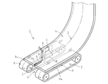
- FIG. 2 is a perspective view of a principal part showing an implementation status of the sheet glass cutting device and the cutting method according to the second embodiment of the present invention.
- the pair of support members are each constituted by a conveyor belt 8 of a conveyor 7 (may be a plurality of conveyor rollers of a roller conveyor), and these conveyors
- the belt 8 is driven at the same speed in the direction of the arrow a so as to send the strip-shaped glass sheet G in the direction along the planned cutting line 5.
- Each of the conveyor belts 8 has a support surface 8a that holds the plate-like glass sheet G by suction or the like on each outer peripheral surface, and the planned cutting line 5 that exists at the center in the width direction of the belt-like plate glass G.
- a space S is formed over the entire length in the longitudinal direction of the conveyor 7 on the back side of the planned cutting line 5 of the belt-like plate-like glass G.
- this cutting device 1 is provided with the local heating means 3 which performs local heating with the laser beam L on the planned cutting line 5 of the strip
- the transport belt 8 of the conveyor 7 sends the strip-shaped glass sheet G, so that the heating region H by the local heating means 3 is strip-shaped plate-shaped prior to the cooling region C by the cooling means 4.
- the glass G is scanned on the planned cutting line 5 from one end side.
- FIG. 3 is a perspective view of a main part showing the state of implementation of the sheet glass cutting device and the cutting method according to the third embodiment of the present invention.
- the cutting device 1 according to the third embodiment cuts relatively thick ears Gx existing at both ends in the width direction of the band-shaped plate glass G.
- the planned cutting lines 5 exist slightly at the center position in the width direction of the ear part Gx.
- a pair of conveyors 7 that support and send the belt-like plate-like glass G from the back surface side are arranged at portions separated from both sides of each of the planned cutting lines 5, and the back surface of the planned cutting line 5.
- a space S is provided on the side.
- a local heating means 3 that performs local heating and a cooling means 4 that jets the cooling water W are disposed on the planned cutting lines 5.
- One or a plurality (one in the illustrated example) of auxiliary conveyors 9 for preventing the sheet glass G from drooping are installed on the back surface side in the central region in the width direction of the belt-shaped sheet glass G.
- belt-shaped plate-shaped glass G is short, not only the auxiliary conveyor 9 is unnecessary but two conveyors each arrange
- the heating area H by the local heating means 3 and the cooling area C by the cooling means 4 are respectively By scanning the planned cutting line 5, the band-shaped plate glass G is cut in full body between the effective portion Ga and the ear portion Gx as the initial crack 6a progresses, and thereby the ear portion Gx.
- Other configurations, operational effects, and supplementary explanation items are the same as those in the first embodiment described above. Therefore, the description thereof is omitted here, and the same reference numerals are used for common components.
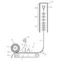
- FIG. 4 is a schematic side view showing a state of implementation of the sheet glass cutting device and the cutting method according to the fourth embodiment of the present invention.
- a molding apparatus 10 for molding a strip-shaped glass sheet G, and the strip-shaped glass sheet G after the molding are wound around a core 11a in a roll shape.
- the above-described cutting device 1 shown in FIG. 3 is interposed between the winding device 11. That is, the molding apparatus 10 performs an overflow downdraw method, and in order from the top, a molding zone 10A having a molded body 10x in a molding furnace, and a slow cooling zone 10B having an annealing means (annealer) And a cooling zone 10C having a cooling means.
- annealing means annealer
- the strip-shaped glass sheet G drawn downward from the cooling zone 10C of the molding apparatus 10 is smoothly curved and sent in the lateral direction by the conversion roller 12, and is conveyed to the conveyor belt 8 in the conveyor 7 of the cutting apparatus 1. It will be in the state supported by adsorption
- the local heating means 3 and the cooling means 4 perform local heating and cooling on the planned cutting line 5.
- the belt-like plate glass G is cut in full body between the effective portion Ga and the ear portion Gx.
- the effective portion Ga of the sheet glass G is wound around the core 11a of the winding device 11 in a roll shape, and when the roll outer diameter reaches a predetermined value, the sheet glass G is widened. Cut in the direction. This cutting is performed by, for example, putting a scribe in the width direction of the sheet glass G and breaking it with a cutter. As a result, a roll-shaped glass roll as a final product is obtained.
- the protective sheet winding body 13 is disposed above the core 11 a of the winding device 11, and the protective sheet 14 drawn out from the protective sheet winding body 13 is a plate-like glass G. Is wound around the core 11a in a roll shape in a state of being overlapped on the surface side of the effective portion Ga.
- belt-shaped plate-shaped glass G is sent below, and is discarded.
- the configuration of the cutting device 1 and the operation and effect thereof are substantially the same as those of the third embodiment described above, the description thereof is omitted here, and the same reference numerals are used for common components. .
- FIG. 5 is a schematic side view showing a state of implementation of the sheet glass cutting device and the cutting method according to the fifth embodiment of the present invention.
- the fifth embodiment is different from the above-described fourth embodiment in that the belt-like plate glass G drawn from the cooling zone 10C of the forming apparatus 10 is wound up in a roll shape without cutting off the ear portion Gx.
- the band-shaped plate glass G drawn out from the original glass wound body 15 is sent in the horizontal direction, while undergoing the cutting process of the ear portion Gx in the cutting device 1, By winding in a roll around the winding core 11a of the winding device 11, a glass roll as a final product is obtained.
- the protective sheet winding body 13 is disposed above the core 11a of the winding device 11, and the protective sheet 14 drawn out from the protective sheet winding body 13 is a plate. In a state of being overlaid on the surface side of the effective portion Ga of the glassy glass G, it is wound around the winding core 11a in a roll shape to obtain a glass wound body as a final product.
- FIG. 6 is a schematic side view which shows the implementation condition of the sheet glass cutting device which concerns on 6th Embodiment of this invention, and its cutting method.
- the sixth embodiment differs from the fourth or fifth embodiment described above in that the strip-shaped glass sheet G drawn from the cooling zone 10C of the molding apparatus 10 or the original glass roll 15 is laterally arranged. While cutting, the ear portion Gx of the sheet glass G is cut out, and then, after passing through a two-dividing step in the cutting device 1, by winding it around the two cores 11 a of the winding device 11 in a roll shape, respectively. In addition, two glass rolls as the final product are obtained.
- the protection sheet 14 pulled out from each protection sheet winding body 13 rolls around the core 11a in the state where it overlapped with the back surface side of the effective part Ga of the sheet glass G, respectively. Rolled up into a shape.
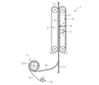
- FIG. 7 is a schematic side view showing a state of implementation of the sheet glass cutting device and the cutting method according to the seventh embodiment of the present invention.
- the cutting device 1 according to the seventh embodiment is basically different from the above-described second to sixth embodiments in that a conveyor belt 8 as a support member in one conveyor 7 and a conveyor 7z in another conveyor 7z.
- the belt-shaped glass sheet G is supported by the conveying belt 8z as a pressing member in a sandwiched state.
- the belt-shaped glass sheet G is directed downward in a vertical posture. It is in the point being sent.
- the structure of the conveying belt 8 as the support member and the conveying belt 8z as the pressing member are substantially the same, and both the conveying belts 8 and 8z are arranged to face each other, and each of them is in the a direction and b. Driven at the same speed in the direction.
- an organic film for example, organic resin film
- an organic film is interposed between both of them 8z and G. It is preferable to make it. Since the configuration for cutting the strip-shaped glass sheet G in full body by the cutting device 1 and the operation and effect thereof are substantially the same as those of the second to sixth embodiments, the description thereof is omitted here.
- belt-shaped plate-shaped glass G is not specifically limited, The centerline of the length direction of the plate-shaped glass G inclines with respect to the horizontal, even if it is a flat position (horizontal position). It is possible to apply this configuration.
- FIG. 8 shows an organic layer (preferably an organic resin layer) 16 formed on the cut surface 6 of the sheet glass G (Ga) cut by the cutting device 1 in the above embodiment.
- the organic layer 16 is formed at both ends, but the cut is only performed at one end in the width direction of the plate glass G (Ga).
- the organic layer 16 may be formed only at the one end. In this way, since the strength of the cut surface 6 of the sheet glass G is increased, in the sheet glass G having a thickness of 200 ⁇ m or less, sufficient strength against bending can be secured, and a thin plate The flexibility of the glass sheet G can be effectively utilized.
- FIG. 9 shows an example in which an organic layer (preferably an organic resin layer) 16 is formed on the surface of the sheet glass G (Ga) cut by the cutting device 1 in the above embodiment. Even in such a case, the strength of the surface of the sheet glass G (Ga) is increased, so that sufficient strength against bending can be secured, and the thin sheet glass G (Ga). Can effectively utilize the flexibility.
- an organic layer preferably an organic resin layer
- the sheet glass G is cut through a full body by so-called thermal stress cleaving, but the present invention can be similarly applied to a case where the sheet glass G is cut through a full body by fusing. It is.
- Example 1 a non-alkali glass plate having a long side of 460 mm, a short side of 360 mm, a thickness of 200 ⁇ m, and a thermal expansion coefficient of 38 ⁇ 10 ⁇ 7 / ° C. is used.
- a support surface of a pair of support members made of a stainless steel workbench arranged with a space having a width of 20 mm on the side it was placed via a foamed polyethylene sheet as an organic layer (basically shown in FIG. 1). Status).
- Example 2 of the present invention the long side is 460 mm, the short side is 50 [mu] m 360 mm, a thickness, and the non-alkali glass plate in thermal expansion coefficient 38 ⁇ 10 -7 / °C, as in Example 1 above
- laser cleaving was carried out with a carbon dioxide laser output of 100 w and a cutting speed of 700 mm / sec.
- 50 samples Sa made of plate glass having a width of 15 mm and a length of 360 mm could be produced by full body cutting.
- the fracture strength was 220 MPa at the lowest value and 600 MPa as the average value, which was compared with Comparative Example 1 described later. Then, the average value was 3 times or more.
- Example 3 a non-alkali glass plate having a long side of 460 mm, a short side of 360 mm, a thickness of 100 ⁇ m, and a thermal expansion coefficient of 38 ⁇ 10 ⁇ 7 / ° C.
- laser cleaving was carried out with a carbon dioxide laser output of 40 w and a cutting speed of 150 mm / sec.
- 50 samples Sa made of plate glass having a width of 15 mm and a length of 360 mm could be produced by full body cutting.
- the ultraviolet curable acrylic resin was apply
- the # 2000 sandpaper was used to scratch the top surface of the UV curable resin with a load of 1N, and then evaluated by the same method as in Example 1 above.
- the minimum value was 200 MPa, the average value was 530 MPa, and the strength of the cut surface did not decrease.
- a strip-shaped plate glass made of non-alkali glass having a length of 250 m, a width of 600 mm, a thickness of 100 ⁇ m, and a thermal expansion coefficient of 38 ⁇ 10 ⁇ 7 / ° C. is used as the core.
- the glass winding body is manufactured by winding around the area, and then the both ends in the width direction are shown in FIG. 3 as described above while being drawn out from the glass winding body as a band-shaped plate glass. 50 mm each was cut in substantially the same manner.
- Example 5 a non-alkali glass plate having a long side of 460 mm, a short side of 360 mm, a thickness of 300 ⁇ m, and a thermal expansion coefficient of 38 ⁇ 10 ⁇ 7 / ° C.
- laser cleaving was attempted at a carbon dioxide laser output of 10 to 200 w and a cutting speed of 50 mm / sec to 700 mm / sec.
- full-body cutting could be performed by adjusting the output of the carbon dioxide gas laser and the cutting speed.
Landscapes
- Chemical & Material Sciences (AREA)
- Engineering & Computer Science (AREA)
- Materials Engineering (AREA)
- Organic Chemistry (AREA)
- Physics & Mathematics (AREA)
- Health & Medical Sciences (AREA)
- Optics & Photonics (AREA)
- Toxicology (AREA)
- Thermal Sciences (AREA)
- Re-Forming, After-Treatment, Cutting And Transporting Of Glass Products (AREA)
Abstract
Description
巻き取られる。
2 支持部材
2a 支持面
3 局部加熱手段
4 冷却手段
5 切断予定線
6 切断面
6a 初期亀裂
8 搬送ベルト(支持部材)
8a 支持面
10 成形装置
11 巻取装置
11a 巻芯
14 保護シート
G 板状ガラス(ガラスフィルム)
Ga 有効部
Gx 耳部
H 加熱領域
C 冷却領域
Claims (19)
- 板状ガラスの切断予定線に沿って少なくとも局部加熱を行うことにより、該板状ガラスを切断する方法において、
前記板状ガラスの切断予定線から両側に離隔した部位を裏面側からそれぞれ支持する支持部材を、前記切断予定線の裏面側に空間が形成されるように相互に離隔して配置した状態で、前記板状ガラスの切断予定線に沿って少なくとも局部加熱を行うことにより、該板状ガラスをフルボディ切断することを特徴とする板状ガラスの切断方法。 - 前記板状ガラスの切断予定線上に初期亀裂を形成した後、該切断予定線に沿う局部加熱及びその加熱領域に対する冷却に伴って発生する応力により、前記初期亀裂を進展させて前記板状ガラスをフルボディ切断することを特徴とする請求項1に記載の板状ガラスの切断方法。
- 前記板状ガラスが、連続的に送られる帯状の板状ガラスであると共に、前記切断予定線が該帯状の板状ガラスの送り方向に沿って延びており、且つ、該帯状の板状ガラスを前記切断予定線に沿って連続的にフルボディ切断することを特徴とする請求項1または2に記載の板状ガラスの切断方法。
- 前記支持部材が、前記帯状の板状ガラスを連続して送るように駆動されることを特徴とする請求項3に記載の板状ガラスの切断方法。
- 前記切断予定線が、前記帯状の板状ガラスを幅方向の任意の部位で連続的に分断する位置に存在していることを特徴とする請求項3または4に記載の板状ガラスの切断方法。
- 前記切断予定線が、前記帯状の板状ガラスの幅方向両端に形成された耳部を連続的に切除する位置に存在していることを特徴とする請求項3~5の何れかに記載の板状ガラスの切断方法。
- 前記連続的に送られる帯状の板状ガラスが、成形装置の徐冷ゾーンを経て冷却された後に送られる帯状の板状ガラスであることを特徴とする請求項3~6の何れかに記載の板状ガラスの切断方法。
- 前記連続的に送られる帯状の板状ガラスが前記切断予定線に沿って連続的にフルボディ切断されながら、巻芯の廻りにロール状に巻き取られることを特徴とする請求項3~7の何れかに記載の板状ガラスの切断方法。
- 前記板状ガラスの表面側に、前記支持部材とそれぞれ対向して配置され且つ前記板状ガラスを前記支持部材との間で挟持する押え部材を配設したことを特徴とする請求項1~8の何れかに記載の板状ガラスの切断方法。
- 前記板状ガラスの裏面と前記支持部材の支持面との間に有機層を介在させたことを特徴とする請求項1~9の何れかに記載の板状ガラスの切断方法。
- 前記板状ガラスの表面と前記押え部材の押え面との間に有機層を介在させたことを特徴とする請求項10に記載の板状ガラスの切断方法。
- 前記板状ガラスの厚みが200μm以下であることを特徴とする請求項1~11の何れかに記載の板状ガラスの切断方法。
- 前記局部加熱が、炭酸ガスレーザーにより行われることを特徴とする請求項1~12の何れかに記載の板状ガラスの切断方法。
- 請求項1~13の何れかに記載の方法により少なくとも一辺が切断されてなり且つ厚みが200μm以下であることを特徴とする板状ガラス。
- 請求項1~13の何れかに記載の方法により少なくとも一辺が切断されてなり且つ切断面の曲げ強度が200MPa以上であると共に厚みが200μm以下であることを特徴とする板状ガラス。
- 請求項8に記載の方法により切断されてなり且つ巻芯の廻りにロール状に巻き取られていることを特徴とする板状ガラス巻回体。
- 請求項1~13の何れかに記載の方法により切断された切断面及び表裏面の少なくとも一面に有機層を形成したことを特徴とする板状ガラス。
- 板状ガラスの切断予定線に沿って局部加熱を行う局部加熱手段を備えた板状ガラスの切断装置において、
前記板状ガラスの切断予定線から両側に離隔した部位を裏面側からそれぞれ支持する支持部材を、前記切断予定線の裏面側に空間が形成されるように相互に離隔して配置すると共に、これらの支持部材により支持された前記板状ガラスの切断予定線に沿って少なくとも局部加熱手段により局部加熱を行うことにより、該板状ガラスをフルボディ切断するように構成したことを特徴とする板状ガラスの切断装置。 - 前記板状ガラスの切断予定線上に初期亀裂を形成する亀裂形成手段と、前記局部加熱手段により局部加熱された加熱領域を冷却する冷却手段とをさらに備え、前記局部加熱手段及び冷却手段によって応力を発生させることにより、前記初期亀裂を進展させて前記板状ガラスをフルボディ切断するように構成したことを特徴とする請求項1に記載の板状ガラスの切断装置。
Priority Applications (4)
| Application Number | Priority Date | Filing Date | Title |
|---|---|---|---|
| CN201180067094.9A CN103347827B (zh) | 2011-06-07 | 2011-06-07 | 板状玻璃的切断方法及其切断装置 |
| PCT/JP2011/062995 WO2012169002A1 (ja) | 2011-06-07 | 2011-06-07 | 板状ガラスの切断方法及びその切断装置 |
| KR1020137015945A KR101732445B1 (ko) | 2011-06-07 | 2011-06-07 | 판형상 유리의 절단방법 및 그 절단장치 |
| US14/007,018 US9458047B2 (en) | 2011-06-07 | 2011-06-07 | Method for cutting plate-like glass, and cutting device therefor |
Applications Claiming Priority (1)
| Application Number | Priority Date | Filing Date | Title |
|---|---|---|---|
| PCT/JP2011/062995 WO2012169002A1 (ja) | 2011-06-07 | 2011-06-07 | 板状ガラスの切断方法及びその切断装置 |
Publications (1)
| Publication Number | Publication Date |
|---|---|
| WO2012169002A1 true WO2012169002A1 (ja) | 2012-12-13 |
Family
ID=47295609
Family Applications (1)
| Application Number | Title | Priority Date | Filing Date |
|---|---|---|---|
| PCT/JP2011/062995 Ceased WO2012169002A1 (ja) | 2011-06-07 | 2011-06-07 | 板状ガラスの切断方法及びその切断装置 |
Country Status (4)
| Country | Link |
|---|---|
| US (1) | US9458047B2 (ja) |
| KR (1) | KR101732445B1 (ja) |
| CN (1) | CN103347827B (ja) |
| WO (1) | WO2012169002A1 (ja) |
Cited By (7)
| Publication number | Priority date | Publication date | Assignee | Title |
|---|---|---|---|---|
| WO2015029669A1 (ja) * | 2013-08-28 | 2015-03-05 | 日本電気硝子株式会社 | 薄板ガラスの搬送方法、搬送装置、および切断方法、並びにガラス物品の製造方法 |
| JP2015044713A (ja) * | 2013-08-28 | 2015-03-12 | 日本電気硝子株式会社 | 薄板ガラスの切断方法、およびガラス物品の製造方法 |
| JP2015044712A (ja) * | 2013-08-28 | 2015-03-12 | 日本電気硝子株式会社 | 薄板ガラスの搬送方法および搬送装置 |
| CN105307992A (zh) * | 2013-08-28 | 2016-02-03 | 日本电气硝子株式会社 | 玻璃膜带制造方法以及玻璃膜带制造装置 |
| JP2017154907A (ja) * | 2016-02-29 | 2017-09-07 | 日本電気硝子株式会社 | ガラス基板の熱処理方法 |
| KR20200102544A (ko) * | 2013-08-28 | 2020-08-31 | 니폰 덴키 가라스 가부시키가이샤 | 유리 필름 리본 제조 방법 및 유리 필름 리본 제조 장치 |
| CN114276005A (zh) * | 2021-12-22 | 2022-04-05 | 无锡市伟友汽摩配件有限公司 | 一种后视镜生产线 |
Families Citing this family (14)
| Publication number | Priority date | Publication date | Assignee | Title |
|---|---|---|---|---|
| WO2015084668A1 (en) | 2013-12-03 | 2015-06-11 | Corning Incorporated | Apparatus and method for severing a glass sheet |
| US20170174549A1 (en) * | 2014-04-04 | 2017-06-22 | Corning Incorporated | Method and system for scoring glass sheet |
| US10570047B2 (en) * | 2014-07-08 | 2020-02-25 | Corning Incorporated | Continuous processing of flexible glass ribbon |
| CN107635932B (zh) | 2015-05-18 | 2021-12-07 | 康宁股份有限公司 | 用于加工玻璃带的方法和系统 |
| LT3529214T (lt) * | 2016-10-24 | 2021-02-25 | Corning Incorporated | Substrato apdorojimo stotis lakšto formos stiklo substratų lazeriniam mašininiam apdorojimui |
| JP6748920B2 (ja) * | 2017-03-13 | 2020-09-02 | 日本電気硝子株式会社 | ガラスフィルムの製造方法 |
| WO2018210519A1 (de) | 2017-05-19 | 2018-11-22 | Schott Ag | Bauteil, umfassend glas oder glaskeramik, mit entlang einer vorgegebenen trennlinie angeordneten vorschädigungen, verfahren und vorrichtung zur herstellung des bauteils und dessen verwendung |
| TWI813592B (zh) * | 2017-10-30 | 2023-09-01 | 美商康寧公司 | 用於處理薄玻璃帶的系統及方法 |
| CN108656371B (zh) * | 2018-05-03 | 2020-10-27 | 广州国显科技有限公司 | 屏体制造方法及使用该方法制造的oled屏体 |
| JP7022389B2 (ja) * | 2018-05-31 | 2022-02-18 | 日本電気硝子株式会社 | ガラスフィルムの製造方法 |
| CN109553290B (zh) * | 2019-01-22 | 2024-04-26 | 安徽瑞龙玻璃机械股份有限公司 | 一种能够对切的玻璃切割机 |
| WO2020213377A1 (ja) * | 2019-04-18 | 2020-10-22 | 日本電気硝子株式会社 | 保護シート切断装置及びガラス基板梱包体の製造方法 |
| JP7336071B2 (ja) * | 2019-10-08 | 2023-08-31 | 日本電気硝子株式会社 | 板ガラスの製造方法及びその製造装置 |
| JP7640936B2 (ja) * | 2019-12-24 | 2025-03-06 | 日本電気硝子株式会社 | ガラスフィルムの製造方法、ガラスロールの製造方法、及びガラスフィルムの製造装置 |
Citations (4)
| Publication number | Priority date | Publication date | Assignee | Title |
|---|---|---|---|---|
| JPH0230390A (ja) * | 1988-07-21 | 1990-01-31 | Fuji Electric Co Ltd | レーザ加工方法 |
| JPH0768395A (ja) * | 1993-09-01 | 1995-03-14 | Hitachi Cable Ltd | ガラスの切断方法およびその装置 |
| JP2004505881A (ja) * | 2000-08-16 | 2004-02-26 | カール−ツァイス−スティフツング | 個々のガラス板を製作するための方法及び装置 |
| JP2010132531A (ja) * | 2008-10-01 | 2010-06-17 | Nippon Electric Glass Co Ltd | ガラスロール、ガラスロールの製造装置、及びガラスロールの製造方法 |
Family Cites Families (12)
| Publication number | Priority date | Publication date | Assignee | Title |
|---|---|---|---|---|
| GB338778A (en) * | 1929-12-24 | 1930-11-27 | Pittsburgh Plate Glass Co | Improvements in or relating to apparatus for severing the edges of glass sheets |
| GB1246481A (en) * | 1968-03-29 | 1971-09-15 | Pilkington Brothers Ltd | Improvements in or relating to the cutting of glass |
| US5776220A (en) * | 1994-09-19 | 1998-07-07 | Corning Incorporated | Method and apparatus for breaking brittle materials |
| JPH08174260A (ja) | 1994-12-21 | 1996-07-09 | Hitachi Cable Ltd | レーザ加工方法及びその装置 |
| EP0903327A3 (en) * | 1997-09-17 | 1999-07-28 | Nec Corporation | Method for separating non-metal material |
| JP2005263578A (ja) * | 2004-03-19 | 2005-09-29 | Shibaura Mechatronics Corp | 脆性材料の割断加工システム及びその方法 |
| JP3887394B2 (ja) * | 2004-10-08 | 2007-02-28 | 芝浦メカトロニクス株式会社 | 脆性材料の割断加工システム及びその方法 |
| JP2006199553A (ja) | 2005-01-24 | 2006-08-03 | Sharp Corp | 基板分断装置及び基板分断方法 |
| JP2009040665A (ja) | 2007-08-12 | 2009-02-26 | Lemi Ltd | 脆性材料のフルボディ割断方法 |
| JP5788134B2 (ja) | 2008-10-01 | 2015-09-30 | 日本電気硝子株式会社 | ガラスロール及びガラスロールの製造方法 |
| US8656738B2 (en) * | 2008-10-31 | 2014-02-25 | Corning Incorporated | Glass sheet separating device |
| US8245540B2 (en) * | 2009-02-24 | 2012-08-21 | Corning Incorporated | Method for scoring a sheet of brittle material |
-
2011
- 2011-06-07 US US14/007,018 patent/US9458047B2/en active Active
- 2011-06-07 WO PCT/JP2011/062995 patent/WO2012169002A1/ja not_active Ceased
- 2011-06-07 KR KR1020137015945A patent/KR101732445B1/ko active Active
- 2011-06-07 CN CN201180067094.9A patent/CN103347827B/zh active Active
Patent Citations (4)
| Publication number | Priority date | Publication date | Assignee | Title |
|---|---|---|---|---|
| JPH0230390A (ja) * | 1988-07-21 | 1990-01-31 | Fuji Electric Co Ltd | レーザ加工方法 |
| JPH0768395A (ja) * | 1993-09-01 | 1995-03-14 | Hitachi Cable Ltd | ガラスの切断方法およびその装置 |
| JP2004505881A (ja) * | 2000-08-16 | 2004-02-26 | カール−ツァイス−スティフツング | 個々のガラス板を製作するための方法及び装置 |
| JP2010132531A (ja) * | 2008-10-01 | 2010-06-17 | Nippon Electric Glass Co Ltd | ガラスロール、ガラスロールの製造装置、及びガラスロールの製造方法 |
Cited By (19)
| Publication number | Priority date | Publication date | Assignee | Title |
|---|---|---|---|---|
| CN105307992B (zh) * | 2013-08-28 | 2018-03-20 | 日本电气硝子株式会社 | 玻璃膜带制造方法以及玻璃膜带制造装置 |
| CN107382048B (zh) * | 2013-08-28 | 2020-03-27 | 日本电气硝子株式会社 | 玻璃膜带制造方法以及玻璃膜带制造装置 |
| JP2015044712A (ja) * | 2013-08-28 | 2015-03-12 | 日本電気硝子株式会社 | 薄板ガラスの搬送方法および搬送装置 |
| US9932259B2 (en) | 2013-08-28 | 2018-04-03 | Nippon Electric Glass Co., Ltd. | Glass film ribbon manufacturing method and glass film ribbon manufacturing device |
| KR20160048718A (ko) * | 2013-08-28 | 2016-05-04 | 니폰 덴키 가라스 가부시키가이샤 | 유리 필름 리본 제조 방법 및 유리 필름 리본 제조 장치 |
| KR102221540B1 (ko) * | 2013-08-28 | 2021-03-02 | 니폰 덴키 가라스 가부시키가이샤 | 유리 필름 리본 제조 방법 및 유리 필름 리본 제조 장치 |
| KR102184301B1 (ko) | 2013-08-28 | 2020-11-30 | 니폰 덴키 가라스 가부시키가이샤 | 유리 필름 리본 제조 방법 및 유리 필름 리본 제조 장치 |
| CN107382048A (zh) * | 2013-08-28 | 2017-11-24 | 日本电气硝子株式会社 | 玻璃膜带制造方法以及玻璃膜带制造装置 |
| JP2015044713A (ja) * | 2013-08-28 | 2015-03-12 | 日本電気硝子株式会社 | 薄板ガラスの切断方法、およびガラス物品の製造方法 |
| EP3326978A1 (en) * | 2013-08-28 | 2018-05-30 | Nippon Electric Glass Co., Ltd. | Glass film ribbon manufacturing method and glass film ribbon manufacturing device |
| CN105307992A (zh) * | 2013-08-28 | 2016-02-03 | 日本电气硝子株式会社 | 玻璃膜带制造方法以及玻璃膜带制造装置 |
| TWI644871B (zh) * | 2013-08-28 | 2018-12-21 | 日商日本電氣硝子股份有限公司 | 玻璃膜帶的製造方法以及玻璃膜帶的製造裝置 |
| US10202299B2 (en) | 2013-08-28 | 2019-02-12 | Nippon Electric Glass Co., Ltd. | Glass film ribbon manufacturing method and glass film ribbon manufacturing device |
| WO2015029669A1 (ja) * | 2013-08-28 | 2015-03-05 | 日本電気硝子株式会社 | 薄板ガラスの搬送方法、搬送装置、および切断方法、並びにガラス物品の製造方法 |
| KR20200102544A (ko) * | 2013-08-28 | 2020-08-31 | 니폰 덴키 가라스 가부시키가이샤 | 유리 필름 리본 제조 방법 및 유리 필름 리본 제조 장치 |
| WO2017150111A1 (ja) * | 2016-02-29 | 2017-09-08 | 日本電気硝子株式会社 | ガラス基板の熱処理方法 |
| JP2017154907A (ja) * | 2016-02-29 | 2017-09-07 | 日本電気硝子株式会社 | ガラス基板の熱処理方法 |
| CN114276005A (zh) * | 2021-12-22 | 2022-04-05 | 无锡市伟友汽摩配件有限公司 | 一种后视镜生产线 |
| CN114276005B (zh) * | 2021-12-22 | 2022-09-16 | 无锡市伟友汽摩配件有限公司 | 一种后视镜生产线 |
Also Published As
| Publication number | Publication date |
|---|---|
| KR101732445B1 (ko) | 2017-05-04 |
| KR20140012957A (ko) | 2014-02-04 |
| CN103347827B (zh) | 2016-10-26 |
| CN103347827A (zh) | 2013-10-09 |
| US9458047B2 (en) | 2016-10-04 |
| US20140017475A1 (en) | 2014-01-16 |
Similar Documents
| Publication | Publication Date | Title |
|---|---|---|
| JP5522516B2 (ja) | 板状ガラスの切断方法及びその切断装置 | |
| KR101732445B1 (ko) | 판형상 유리의 절단방법 및 그 절단장치 | |
| KR101800224B1 (ko) | 판형상 유리의 절단방법 및 그 절단장치 | |
| JP5532219B2 (ja) | 板状ガラスの切断方法及びその切断装置 | |
| US9840028B2 (en) | Cleaving method for a glass film | |
| CN105143123B (zh) | 脆性材料的板材的分断方法及分断装置 | |
| JP2011144093A (ja) | 板状ガラスの製造方法及びその装置 | |
| JP5510650B2 (ja) | ガラスフィルムの割断方法及び製造方法 | |
| JP2015057366A (ja) | 板状ガラスの切断方法及びその切断装置 | |
| WO2015029669A1 (ja) | 薄板ガラスの搬送方法、搬送装置、および切断方法、並びにガラス物品の製造方法 | |
| US20190161385A1 (en) | Glass film production method | |
| JP5708782B2 (ja) | 板状ガラスの切断方法及びその切断装置 | |
| US10889519B2 (en) | Method for manufacturing glass roll | |
| JP2014101269A (ja) | ガラスフィルムの切断方法 | |
| CN109311721B (zh) | 带状玻璃膜的制造方法以及制造装置 | |
| JP5521814B2 (ja) | 薄板ガラスロールならびにその製造方法および製造装置 | |
| TWI500586B (zh) | 板狀玻璃的切割方法以及其切割裝置 | |
| JP5500377B2 (ja) | ガラスフィルムの製造方法及び製造装置 | |
| US12421152B2 (en) | Method for producing glass film | |
| TWI492908B (zh) | 板狀玻璃的切割方法以及其切割裝置 | |
| JP6445863B2 (ja) | 脆性材料の板材の分断方法及び分断装置 |
Legal Events
| Date | Code | Title | Description |
|---|---|---|---|
| 121 | Ep: the epo has been informed by wipo that ep was designated in this application |
Ref document number: 11867559 Country of ref document: EP Kind code of ref document: A1 |
|
| ENP | Entry into the national phase |
Ref document number: 20137015945 Country of ref document: KR Kind code of ref document: A |
|
| WWE | Wipo information: entry into national phase |
Ref document number: 14007018 Country of ref document: US |
|
| NENP | Non-entry into the national phase |
Ref country code: DE |
|
| 122 | Ep: pct application non-entry in european phase |
Ref document number: 11867559 Country of ref document: EP Kind code of ref document: A1 |
|
| NENP | Non-entry into the national phase |
Ref country code: JP |