WO2012164671A1 - Dispositif de gestion de système informatique et procédé de gestion - Google Patents
Dispositif de gestion de système informatique et procédé de gestion Download PDFInfo
- Publication number
- WO2012164671A1 WO2012164671A1 PCT/JP2011/062412 JP2011062412W WO2012164671A1 WO 2012164671 A1 WO2012164671 A1 WO 2012164671A1 JP 2011062412 W JP2011062412 W JP 2011062412W WO 2012164671 A1 WO2012164671 A1 WO 2012164671A1
- Authority
- WO
- WIPO (PCT)
- Prior art keywords
- cache
- data
- page
- storage area
- access request
- Prior art date
Links
Images


Classifications
-
- G—PHYSICS
- G06—COMPUTING; CALCULATING OR COUNTING
- G06F—ELECTRIC DIGITAL DATA PROCESSING
- G06F3/00—Input arrangements for transferring data to be processed into a form capable of being handled by the computer; Output arrangements for transferring data from processing unit to output unit, e.g. interface arrangements
- G06F3/06—Digital input from, or digital output to, record carriers, e.g. RAID, emulated record carriers or networked record carriers
- G06F3/0601—Interfaces specially adapted for storage systems
- G06F3/0602—Interfaces specially adapted for storage systems specifically adapted to achieve a particular effect
- G06F3/061—Improving I/O performance
-
- G—PHYSICS
- G06—COMPUTING; CALCULATING OR COUNTING
- G06F—ELECTRIC DIGITAL DATA PROCESSING
- G06F11/00—Error detection; Error correction; Monitoring
- G06F11/30—Monitoring
- G06F11/34—Recording or statistical evaluation of computer activity, e.g. of down time, of input/output operation ; Recording or statistical evaluation of user activity, e.g. usability assessment
- G06F11/3409—Recording or statistical evaluation of computer activity, e.g. of down time, of input/output operation ; Recording or statistical evaluation of user activity, e.g. usability assessment for performance assessment
- G06F11/3433—Recording or statistical evaluation of computer activity, e.g. of down time, of input/output operation ; Recording or statistical evaluation of user activity, e.g. usability assessment for performance assessment for load management
-
- G—PHYSICS
- G06—COMPUTING; CALCULATING OR COUNTING
- G06F—ELECTRIC DIGITAL DATA PROCESSING
- G06F11/00—Error detection; Error correction; Monitoring
- G06F11/30—Monitoring
- G06F11/34—Recording or statistical evaluation of computer activity, e.g. of down time, of input/output operation ; Recording or statistical evaluation of user activity, e.g. usability assessment
- G06F11/3466—Performance evaluation by tracing or monitoring
- G06F11/3485—Performance evaluation by tracing or monitoring for I/O devices
-
- G—PHYSICS
- G06—COMPUTING; CALCULATING OR COUNTING
- G06F—ELECTRIC DIGITAL DATA PROCESSING
- G06F12/00—Accessing, addressing or allocating within memory systems or architectures
- G06F12/02—Addressing or allocation; Relocation
- G06F12/08—Addressing or allocation; Relocation in hierarchically structured memory systems, e.g. virtual memory systems
- G06F12/0802—Addressing of a memory level in which the access to the desired data or data block requires associative addressing means, e.g. caches
- G06F12/0866—Addressing of a memory level in which the access to the desired data or data block requires associative addressing means, e.g. caches for peripheral storage systems, e.g. disk cache
-
- G—PHYSICS
- G06—COMPUTING; CALCULATING OR COUNTING
- G06F—ELECTRIC DIGITAL DATA PROCESSING
- G06F3/00—Input arrangements for transferring data to be processed into a form capable of being handled by the computer; Output arrangements for transferring data from processing unit to output unit, e.g. interface arrangements
- G06F3/06—Digital input from, or digital output to, record carriers, e.g. RAID, emulated record carriers or networked record carriers
- G06F3/0601—Interfaces specially adapted for storage systems
- G06F3/0628—Interfaces specially adapted for storage systems making use of a particular technique
- G06F3/0646—Horizontal data movement in storage systems, i.e. moving data in between storage devices or systems
- G06F3/0647—Migration mechanisms
-
- G—PHYSICS
- G06—COMPUTING; CALCULATING OR COUNTING
- G06F—ELECTRIC DIGITAL DATA PROCESSING
- G06F3/00—Input arrangements for transferring data to be processed into a form capable of being handled by the computer; Output arrangements for transferring data from processing unit to output unit, e.g. interface arrangements
- G06F3/06—Digital input from, or digital output to, record carriers, e.g. RAID, emulated record carriers or networked record carriers
- G06F3/0601—Interfaces specially adapted for storage systems
- G06F3/0668—Interfaces specially adapted for storage systems adopting a particular infrastructure
- G06F3/0671—In-line storage system
- G06F3/0683—Plurality of storage devices
- G06F3/0685—Hybrid storage combining heterogeneous device types, e.g. hierarchical storage, hybrid arrays
-
- G—PHYSICS
- G06—COMPUTING; CALCULATING OR COUNTING
- G06F—ELECTRIC DIGITAL DATA PROCESSING
- G06F2201/00—Indexing scheme relating to error detection, to error correction, and to monitoring
- G06F2201/88—Monitoring involving counting
-
- G—PHYSICS
- G06—COMPUTING; CALCULATING OR COUNTING
- G06F—ELECTRIC DIGITAL DATA PROCESSING
- G06F2201/00—Indexing scheme relating to error detection, to error correction, and to monitoring
- G06F2201/885—Monitoring specific for caches
-
- G—PHYSICS
- G06—COMPUTING; CALCULATING OR COUNTING
- G06F—ELECTRIC DIGITAL DATA PROCESSING
- G06F2212/00—Indexing scheme relating to accessing, addressing or allocation within memory systems or architectures
- G06F2212/10—Providing a specific technical effect
- G06F2212/1016—Performance improvement
-
- G—PHYSICS
- G06—COMPUTING; CALCULATING OR COUNTING
- G06F—ELECTRIC DIGITAL DATA PROCESSING
- G06F2212/00—Indexing scheme relating to accessing, addressing or allocation within memory systems or architectures
- G06F2212/22—Employing cache memory using specific memory technology
- G06F2212/222—Non-volatile memory
-
- G—PHYSICS
- G06—COMPUTING; CALCULATING OR COUNTING
- G06F—ELECTRIC DIGITAL DATA PROCESSING
- G06F2212/00—Indexing scheme relating to accessing, addressing or allocation within memory systems or architectures
- G06F2212/22—Employing cache memory using specific memory technology
- G06F2212/224—Disk storage
-
- G—PHYSICS
- G06—COMPUTING; CALCULATING OR COUNTING
- G06F—ELECTRIC DIGITAL DATA PROCESSING
- G06F2212/00—Indexing scheme relating to accessing, addressing or allocation within memory systems or architectures
- G06F2212/28—Using a specific disk cache architecture
- G06F2212/281—Single cache
-
- G—PHYSICS
- G06—COMPUTING; CALCULATING OR COUNTING
- G06F—ELECTRIC DIGITAL DATA PROCESSING
- G06F2212/00—Indexing scheme relating to accessing, addressing or allocation within memory systems or architectures
- G06F2212/31—Providing disk cache in a specific location of a storage system
- G06F2212/314—In storage network, e.g. network attached cache
-
- G—PHYSICS
- G06—COMPUTING; CALCULATING OR COUNTING
- G06F—ELECTRIC DIGITAL DATA PROCESSING
- G06F3/00—Input arrangements for transferring data to be processed into a form capable of being handled by the computer; Output arrangements for transferring data from processing unit to output unit, e.g. interface arrangements
- G06F3/06—Digital input from, or digital output to, record carriers, e.g. RAID, emulated record carriers or networked record carriers
- G06F3/0601—Interfaces specially adapted for storage systems
- G06F3/0668—Interfaces specially adapted for storage systems adopting a particular infrastructure
- G06F3/067—Distributed or networked storage systems, e.g. storage area networks [SAN], network attached storage [NAS]
Definitions
- the present invention relates to a computer system management apparatus and management method.
- Hierarchical storage technology classifies multiple types of storage devices in a storage device into tiers according to performance.
- the storage destination of data in a logical volume is changed to an appropriate tier based on an I / O (Input / Output) load for the data.
- the hierarchy can be changed manually or automatically. If the tiered storage technology is used, it is possible to allocate a necessary number of storage devices having the performance required for the data to the data. Therefore, the utilization efficiency of the storage device can be improved.
- Patent Document 1 discloses a hierarchical storage technology that can measure an I / O load for each data included in one file and change a data storage destination in units of one file.
- Patent Document 2 discloses a hierarchical storage technology capable of measuring an I / O load for each data included in a virtual storage area called a page and changing a data storage destination in units of one page.
- a host computer that runs an application program may use a cache device that is prepared separately from the storage device.
- a cache device with high I / O performance may be provided.
- the host computer on which the application program runs saves frequently used data in both the storage device and the cache device. By reading the data from the cache device, the application program on the host computer can shorten the read time compared to reading the data from the storage device.
- the application program of the host computer reads the data from the cache device. Therefore, the I / O load on a page including cached data is likely to be measured lower than that of a page including data read from the storage apparatus. This is because the storage device does not know that data is being read from the cache device.
- the cache device deletes a part of stored data when the cache capacity is exhausted. This is called cashout processing. By executing the cache-out process, the free cache capacity can be increased.
- the present invention has been made in view of the above problems, and its object is to measure the data usage status as accurately as possible when the host computer uses both the storage device and the cache device. Another object of the present invention is to provide a computer system management apparatus and management method. Another object of the present invention is associating data stored in a storage area in a logical volume with data stored in a cache device as accurately as possible, and controlling the storage destination of the data based on the use status of the data It is an object of the present invention to provide a management system and management method for a computer system that can be used.
- a management device for managing a computer system is a management device for managing a computer system including a storage device that provides a logical volume to a host computer and a cache device used by the host computer. In the cache device, a part of data stored in a storage area of a predetermined size in the logical volume is stored as cache data.
- the management device includes a microprocessor and a predetermined computer program used by the microprocessor. And a communication interface circuit for communicating with the host computer and the storage device, and the microprocessor executes a predetermined computer program, thereby allowing the host computer to store the storage area in the logical volume.
- the first access request to the data in the cache device is detected, the second access request to the cache data in the cache device by the host computer is detected, and the correspondence between the storage area data in the logical volume and the cache data in the cache device And the total access request to the data in the storage area is calculated based on the first access request and the second access request.
- the microprocessor may send a predetermined instruction to the storage device based on the total access request.
- the predetermined instruction is an instruction for rearranging the data in the storage area based on the total access request, and the storage apparatus arranges the data in the storage area in the physical storage area of the predetermined hierarchy according to the predetermined instruction. Also good.
- the first access request includes both a read request and a write request for data in the storage area
- the second access request includes a read request for cache data
- the total access request includes A total read request obtained by summing a read request for data in the storage area and a read request for cache data corresponding to the storage area, and a write request for data stored in the storage area may be included.
- the predetermined size is different from the size of the cache data, and the microprocessor performs the first timing when the host computer updates the cache data in the cache device, and the first time when the host computer updates the data in the storage area in the logical volume.
- the correspondence relationship between the data in the storage area and the cache data may be detected based on the two timings.
- the microprocessor updates the storage area data updated at the second timing and the latest first timing when the second timing exists within a predetermined time from the previous first timing to the latest first timing. It may be determined that there is a correspondence relationship with the cache data to be processed.
- Cache update history management information for managing the cache data update history by the host computer and storage area update history management information for managing the storage area update history by the host computer are stored in the storage device. Based on the update history management information and the storage area update history management information, the host computer that updates the cache data at the latest first timing is the same as the host computer that updates the data in the storage area at the second timing. In the storage area updated at the second timing and the cache data updated at the latest first timing may be determined to be in a correspondence relationship.
- Correspondence management information for managing the correspondence between the storage area data in the logical volume and the cache data of the cache device is stored in the storage device.
- the correspondence management information includes the reliability of each correspondence relationship.
- the microprocessor may select any one of the correspondence relationships based on the information indicating the reliability when there are a plurality of correspondence relationships between the data in the storage area and the cache data. .
- the present invention can also be understood as a computer program for managing a computer system or a computer system.
- FIG. 1 is an explanatory diagram showing an outline of the embodiment.
- FIG. 2 shows the overall configuration of the computer system.
- FIG. 3 shows the configuration of the management server.
- FIG. 4 shows the configuration of the storage apparatus.
- FIG. 5 shows the configuration of the cache device.
- FIG. 6 shows the configuration of repositories and tables used by the management server.
- FIG. 7 shows a cache read log table.
- FIG. 8 shows a cache write log table.
- FIG. 9 shows a page read log table.
- FIG. 10 shows a page write log table.
- FIG. 11 shows the configuration of a host-logical volume mapping table showing the correspondence between host computers and logical volumes. This is a configuration of a cache-page mapping table showing the correspondence between cache data and pages.
- FIG. 13 shows a page effective load log table.
- FIG. 13 shows a page effective load log table.
- FIG. 14 is a flowchart illustrating processing for acquiring a device log.
- FIG. 15 is a flowchart showing a cache / page mapping process.
- FIG. 16 is a flowchart showing details of a cache-page map search process in the cache-page mapping process.
- FIG. 17 is a flowchart showing details of a process for creating or adding a cache-page map in the cache-page mapping process.
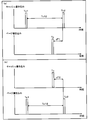
- FIG. 18 is a schematic diagram showing the relationship between cache data update timing and page update timing. (A) shows a case where cache data is updated after a page is updated, and (b) shows cache data is updated. It shows the case where the page is updated after the update.
- FIG. 19 is a flowchart showing details of a process for acquiring the previous cache write time in the cache-page mapping process.
- FIG. 20 is a flowchart showing details of a process for acquiring a logical volume ID in the cache-page mapping process.
- FIG. 21 is a flowchart of a process for calculating the page effective load.
- FIG. 22 is a flowchart showing details of a process of adding the number of page writes in the page effective load calculation process.
- FIG. 23 is a flowchart illustrating details of a process of adding the page read count in the page effective load calculation process.
- FIG. 24 is a flowchart showing details of the process of adding the number of cache reads in the page effective load calculation process.
- FIG. 25 is a flowchart of a process for issuing an instruction for rearranging pages.
- FIG. 26 shows a setting screen of the cache device.
- FIG. 26 shows a setting screen of the cache device.
- FIG. 27 shows a setting screen for mapping the host computer and the logical volume.
- FIG. 28 is an explanatory diagram showing the configuration of the mapping information repository according to the second embodiment.
- FIG. 29 shows a cache-page mapping statistics table.
- FIG. 30 is a flowchart of the cache-page mapping process.
- FIG. 31 is a flowchart of a process for creating or adding a cache-page map in the cache-page mapping process.
- FIG. 32 shows a flowchart of a page-cache mapping process based on statistics in the cache-page mapping process.
- 14 is a flowchart showing cache-page mapping processing according to the third embodiment.
- the information used in the embodiment is described by the expression “aaa table”. However, the information is not limited to this, and for example, “aaa list”, “aaa database”, “aaa queue”, etc. Other expressions may be used. In order to show that the information used in the present embodiment does not depend on the data structure, it may be referred to as “aaa information”.
- identification information In describing the contents of information used in the present embodiment, the expressions “identification information”, “identifier”, “name”, “name”, and “ID” may be used, but these may be replaced with each other. Is possible.
- “computer program” or “module” may be described as an operation subject (subject).
- the program or module is executed by a microprocessor.
- the program or module executes a predetermined process using a memory and a communication port (communication control device). Therefore, the processor may be read as the operation subject (subject). Furthermore, it may be read as processing performed by a computer such as a management server. A part or all of the computer program may be realized by dedicated hardware.
- the computer program may be installed in the computer by a program distribution server or a storage medium.
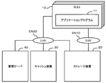
- FIG. 1 shows an overall outline of the embodiment.
- the computer system includes at least one host computer (hereinafter referred to as a host) 1, at least one storage device 2, at least one cache device 3, and at least one management device 4.
- a host a host computer
- storage device a storage device
- cache device a cache device
- management device a management device
- the host 1 and the storage device 2 are connected to be capable of bidirectional communication via a communication network CN1 such as FC_SAN (Fibre Channel_Storage Area Network) or IP_SAN (Internet Protocol_SAN).
- the host 1 and the cache device 3 are connected to be capable of bidirectional communication via a communication network CN2 such as a LAN (Local Area Network) or the Internet.
- the management device 4 is connected to at least the storage device 2 and the cache device 3 via a communication network such as a LAN. Further, the management device 4 and the host 1 may be connected by a LAN or the like.
- an application program 1A runs.
- Examples of the application program 1A include a mail order system, a moving image distribution system, a music distribution system, and a customer management system.
- the storage device 2 includes, for example, at least one logical volume 2A and a plurality of storage devices 2B.
- the storage device 2 also includes a controller (not shown), which is omitted in FIG.
- the plurality of storage devices 2B for example, various devices capable of reading and writing data such as a hard disk device, a semiconductor memory device, an optical disk device, a magneto-optical disk device, a magnetic tape device, and a flexible disk device can be used.
- a hard disk device for example, an FC (Fibre Channel) disk, a SCSI (Small Computer System Interface) disk, a SATA disk, an ATA (AT Attachment) disk, a SAS (Serial Attached SCSI) disk, or the like can be used.
- FC Fibre Channel
- SCSI Serial Computer System Interface
- SATA Serial Advanced Technology Attachment
- SAS Serial Attached SCSI
- flash memory FeRAM (Ferroelectric Random Access Memory), MRAM (Magnetoresistive Random Access)
- Various storage devices such as memory, phase change memory (Ovonic Unified Memory), and RRAM (Resistance RAM) can also be used.
- a configuration in which different types of storage devices such as a flash memory device and a hard disk drive are mixed may be used.
- the plurality of storage devices 2B are divided into a plurality of hierarchies according to their response performance.
- the upper hierarchy UT is a hierarchy composed of relatively high performance storage devices.
- the middle tier MT is a tier composed of relatively medium performance storage devices.
- the lower tier LT is a tier that includes relatively low performance storage devices.
- a RAID (Redundant Arrays of Inexpensive Disks) group is generated by a plurality of storage devices belonging to each hierarchy, and data is stored in units of pages in a physical storage area of the RAID group.
- the logical volume 2A manages data in units of pages as “predetermined size storage areas”.
- the size of the page 2C is, for example, the MB class, and is larger than the size (for example, several hundred to several KB) of cache data CD described later.
- the address space of the logical volume 2A is managed by being divided in units of pages.
- the data of each page 2C is stored in the storage device 2B of the hierarchy determined to be appropriate among the hierarchies UT, MT, LT according to the I / O load.
- the data of the page 2C1 with high access frequency is stored in the storage device of the upper layer UT. Since the response performance of the lower layer LT is low, the data of the page 2C3 with low access frequency is stored in the storage device of the lower layer LT.
- the data of the page 2C2 having an access frequency intermediate between the access frequency of data arranged in the upper layer UT and the access frequency of data arranged in the lower layer LT is arranged.
- the access frequency is an I / O load.
- the cache device 3 is configured, for example, by installing cache management software on a server computer.
- the cache device 3 holds the data CD passed from the host 1 on the cache memory 3A.
- the size of the cache data CD is smaller than the page size. Accordingly, a part of the data in the page 2C is stored in the cache memory 3A as the cache data CD.
- the cache device 3 When the free capacity of the cache memory 3A becomes a predetermined value or less, the cache device 3 deletes the cache data CD selected on the basis of a predetermined standard. Examples of the cache data selected on the basis of the predetermined criteria include cache data having the oldest access time and cache data having the lowest access frequency within a predetermined period.
- the management device 4 is configured, for example, by installing management software on a server computer.
- the management device 4 includes a storage I / O load detection unit 4A, a cache I / O load detection unit 4B, a correspondence relationship detection unit 4C, an I / O load correction unit 4D, and a page relocation instruction unit 4E. Is provided.
- the storage I / O load detection unit 4A detects a read request and a write request to the data of the page 2C by the host 1.
- the storage I / O load detection unit 4A may be expressed as a first access request detection unit, for example.
- the cache I / O load detection unit 4B detects a cache data read request and write request from the host 1.
- the cache I / O load detection unit 4B may be expressed as a second access request detection unit.
- the I / O load is the number of read requests and write requests.
- the correspondence detection unit 4C detects the correspondence between the data of the page 2C and the cache data CD.
- the correspondence relationship detection unit 4C determines which page 2C the cache data CD in the cache device 3 corresponds to, and stores the determination result.
- the I / O load correction unit 4D adds the I / O load to the cache data CD corresponding to the data in the page 2C to the I / O load to the page 2C detected by the storage I / O load detection unit 4A. Addition is performed to calculate a more accurate I / O load of the data of the page 2C.
- the I / O load correction unit 4D may be expressed as a total access request calculation unit, for example.
- the host 1 also stores data frequently used in the application program 1A in the cache memory 3A of the cache device 3.
- the application program 1A reads data held in both the storage device 2 and the cache device 3 from the cache device 3 in order to respond to a user terminal (not shown) at high speed.
- a user terminal not shown
- both the data of the page 2C of the storage device 2 and the cache data CD are updated.
- the data update count does not change between the page 2C data and the cache data CD.
- the number of times data is read is larger for the cache data CD, and the number of times the page 2C including data corresponding to the cache data CD is read is smaller.
- the I / O load correction unit 4D adds a read request of the cache data CD corresponding to the data to the number of times of reading the data of the page 2C in order to eliminate an error due to the imbalance of the number of times of data read. Correct the number of.
- the page relocation instruction unit 4E instructs the storage apparatus 2 to relocate the page 2C based on the corrected I / O load.
- the page rearrangement instruction unit 4E may be expressed as a data rearrangement instruction unit.
- the instruction from the page relocation instruction unit 4E to the storage apparatus 2 includes information for specifying the relocation target page 2C and information indicating the I / O load corrected for the relocation target page.
- the storage apparatus 2 When the storage apparatus 2 receives an instruction from the page relocation instruction unit 4E, it changes the tier of the arrangement destination of the page 2C according to the instruction.
- the page 2C with a low I / O load is arranged in a tier with lower performance than the tier to which it currently belongs.
- the page 2C with a large I / O load is arranged in a higher performance layer than the currently belonging layer.
- the cache data CD is erased from the cache device 3
- the data corresponding to the erased cache data CD is stored in an appropriate hierarchy in the storage device 2 based on the actual I / O load. Has been. Therefore, even when the cache data CD is erased from the cache device 3, the host 1 can read target data from the storage device 2 relatively quickly.
- the host 1 when the host 1 uses both the storage device 2 and the cache device 3, it is possible to correctly evaluate the use status of the data and store it in a hierarchy according to the data. Therefore, in this embodiment, even when the cache data CD is erased, the application program 1A of the host 1 can provide a service to a user terminal outside the figure without significantly reducing the response performance.
- the management apparatus 4 determines the correspondence between the cache data CD and the data of the page 2C, and measures the actual usage of the data of the page 2C. There is no need to be aware of the other party. That is, it is possible to correctly evaluate the data usage status of the page 2C without changing the control program of the storage device 2 and the cache device 3, and based on the evaluation, the page 2C can be arranged in an appropriate hierarchy. Further, the application program 1A of the host 1 may have the same configuration as before.
- the first embodiment will be described with reference to FIGS. First, the correspondence between this embodiment and FIG. 1 will be described.
- the host 1 corresponds to the host 10
- the storage device 2 corresponds to the storage device 20
- the cache device 3 corresponds to the cache device 30
- the management device 4 corresponds to the management server 40.
- the communication network CN1 corresponds to the communication network CN10
- the communication network CN2 corresponds to the communication network CN20.
- the logical volume 2A corresponds to the logical volume 210 in FIG. 2
- the page 2C corresponds to the page 211 in FIG. 2
- the storage device 2B corresponds to the storage devices 250A, 250B, and 250C in FIG.
- the upper layer UT corresponds to the upper layer 251A in FIG. 2
- the middle layer MT corresponds to the middle layer 251B in FIG. 2
- the lower layer LT corresponds to the lower layer 251C in FIG.
- the cache data CD corresponds to the cache data 331 in FIG.
- the disk tier 251A, the disk tier 251B, and the disk tier in the storage device 20 are used.
- the management server 40 for optimizing the usage status of 251C will be described.
- FIG. 2 is a diagram showing the overall configuration of the system.
- the computer system includes a plurality of hosts 10, at least one storage device 20, at least one cache device 30, and at least one management server 40.
- the host 10 is connected to the storage apparatus 20 via the SAN CN 10.
- the host 10, the cache device 30, and the storage device 20 are connected to the management server 40 via the LAN CN 20.
- the host 10 is connected to a plurality of user terminals via a communication network such as the Internet or a LAN.
- the host 10 executes the application program 11 inside.
- the application program 11 is an online shopping application or the like, it is necessary to perpetuate information such as product data to be sold and purchaser's user account data.
- Permanent information (data) means holding information (data) for a long time.
- the host 10 writes such data that needs to be persisted to the storage device 20.
- the host 10 reads data from the storage device 20 as necessary.
- the host 10 uses not only the storage device 20 but also the cache device 30 as a data storage destination.
- the application program 11 is an online shopping application and a particular product among the products handled is particularly popular, the data of the product is frequently referred to.
- the developer of the application program 11 predicts in advance data that will need to be read at high speed.
- the developer can design the application program 11 in advance so that data predicted to be read at high speed is written to both the storage device 20 and the cache device 30. Since the cache device 30 can read data at high speed, it can suppress a decrease in response performance of the application program 11.
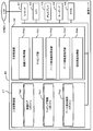
- FIG. 3 is a diagram showing a detailed configuration of the management server 40.
- the management server 40 includes, for example, a communication device 41, a microprocessor 42, a display 43, a keyboard 44, a mouse 45, a main storage device 46, and a secondary storage device 47.
- the management server 40 can bidirectionally communicate with the host 10, the cache device 30, and the storage device 20 via the communication device 41.
- the CPU 42 executes each process described later using an operating system (not shown) stored in the main storage device 46 and the programs P40, P41, P42, P43, and P44.
- the device log acquisition unit P40 is a computer program for acquiring an access log from the storage device 20 and the cache device 30.
- the device log acquisition unit P40 implements the storage I / O detection unit 4A and the cache I / O detection unit 4B shown in FIG.
- the mapping unit P41 is a computer program for managing the correspondence between the host 1 and the logical volume 210 and the correspondence between the page and the cache.
- the correspondence between the host 1 and the logical volume 210 is manually set by the system administrator.
- the correspondence between the page and the cache is automatically created. The creation method will be described later.
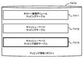
- the mapping unit P41 implements the correspondence relationship detection unit 4C of FIG. 1 together with a mapping information repository T41 described later.
- the page effective load calculation unit P42 is a computer program for calculating an actual I / O load for the data of the page 211. For each page of each logical volume 210, the page effective load calculation unit P42 determines the number of times of writing to the page, the number of times of reading from the page, and the number of times of reading the cache data 331 corresponding to the data included in the page. Based on that, calculate the I / O load that would have actually occurred for that page. The page effective load calculation unit P42 implements the I / O load correction unit 4D of FIG. 1 together with a page effective load repository T42 described later.
- the setting screen processing unit P44 is a computer program for creating a setting screen to be displayed on the display 43 and receiving information input from the user to the setting screen.
- the management server 40 is provided with user interface means such as the display 43 and the keyboard 44.
- a management terminal may be connected to the management server 40 instead.
- the management terminal can be configured as, for example, a personal computer, a portable information terminal, or a mobile phone.
- the user can instruct the management server 40 or display information via a display and a keyboard provided in the management terminal.
- a voice input device may be provided so that the user can instruct the management server 40 by voice.
- the secondary storage device 47 stores a device log repository T40, a mapping information repository T41, and a page effective load repository T42.
- the device log repository T40 stores data used by the device log acquisition unit P40.
- the mapping information repository T41 stores data used in the cache-page mapping unit P41.
- the page effective load repository T42 stores data used by the page effective load calculation unit P42.
- FIG. 4 is a diagram showing a detailed configuration of the storage apparatus 20.
- what is indicated by a solid line is a physical entity.
- What is indicated by a broken line in FIG. 4 is a logical existence or a concept of consolidating physical entities.
- the storage device 20 includes, for example, a port 21, a CPU 22, a communication device 23, a main storage device 24, and a secondary storage device 25.
- the storage device 20 is connected to the SAN CN 10 via the port 21.
- the storage apparatus 20 receives a command from the host 1 via the SAN CN 10 and transmits the processing result of the command to the host 1 via the SAN CN 10.
- the storage device 20 is connected to the LAN CN 20 via the communication device 23.
- the storage device 20 can perform bidirectional communication with the management server 40 via the LAN CN 20.
- the CPU 22 executes the hierarchical management function P20 and the logical volume providing function P21 stored in the main storage device 24. Details of each function will be described later.
- the secondary storage device 25 includes a plurality of disk devices 250A, 250B, and 250C as storage devices. Each disk device 250A, 250B, 250C is hierarchized according to its response performance.
- the response performance is a data writing speed and a data reading speed.
- the upper disk tier 251A is composed of an SSD 250A which is a secondary storage device having high-speed response performance.
- the middle disk tier B is composed of the SAS disk 250B, which has lower response performance than the SSD 250A, but is less expensive.
- the lower disk hierarchy 251C is composed of the SATA disk 250C having the lowest response performance but the cheapest.
- the disk devices 250A, 250B, and 250C are referred to as disk devices 250.
- the recording medium does not have to be disk-shaped, and the shape of the recording medium is not limited.
- the disk hierarchies 251A, 251B, and 251C are called disk hierarchies 251.
- the logical volume providing function P21 provides a volume pool 200 that is a virtual storage capacity resource that aggregates the physical storage capacity of the disk device group.
- the logical volume providing function P21 creates a logical volume 210, which is a logical disk device, by cutting out a physical storage capacity resource of the volume pool 200 by a predetermined size.
- the created logical volume is assigned to the host 10 via the communication port 21. That is, the volume pool 200 is a RAID group (parity group) composed of the respective disk devices 250.
- the host 10 writes the data that needs to be persisted as described above to the logical volume 210 and reads the data as necessary.
- the logical volume 210 is composed of a plurality of pages 211.
- the page 211 is a virtual storage area.
- the logical volume providing function P21 writes the write data received from the host 1 to a predetermined page among the plurality of pages 211 in response to a data write request to the logical volume 210.
- a page corresponding to the write destination address included in the write command (write request) is a predetermined page.
- the logical volume providing function P21 In response to a data read request for the logical volume 210, the logical volume providing function P21 reads specified data from a predetermined page 211 and returns the data to the requesting host 1.
- the predetermined page is a page corresponding to the read destination address included in the read command (read request).
- the logical volume providing function P21 updates the read / write log D20 when processing the read request and the write request.
- the read / write log D20 indicates, for example, information for specifying a page to be requested, information for distinguishing between a read request and a write request, and whether or not the request has been correctly processed. Information, information indicating the time when the request is received, and the like can be included.
- the page 211 is a logical storage area provided in the logical volume 210, and a physical storage area for actually storing data belongs to one of the disk hierarchies 251A, 251B, and 251C. It exists in the disk device 250. That is, when a data write operation or read operation is performed on the page 211, the page 211 logically appears as if it holds data. However, actually, the data is held by the physical disk device 250 belonging to any of the disk hierarchies 251A, 251B, and 251C.
- the hierarchy management function P20 allocates the page 211 to any one of the disk hierarchies 251A, 251B, and 251C.
- the data logically held by the page 211 is physically held by the disk device 250 belonging to the disk hierarchy 251 assigned to the page by the hierarchy management function P20.
- the hierarchy management function P20 measures the number of reads and the number of writes (hereinafter referred to as I / O load) for each page 211.
- the hierarchy management function P20 periodically reassigns each page 211 to any one of the disk hierarchies 251A, 251B, and 251C according to the I / O load. In this way, changing the data storage destination of the page 211 between hierarchies is called page rearrangement.
- the tier management function P20 reassigns the page 211 having a high I / O load among the pages 211 in the logical volume 210 to the disk tier 251A.
- the hierarchy management function P20 reassigns the page 211 having a medium I / O load to the disk hierarchy 251B and reassigns the page 211 having a low I / O load to the disk hierarchy 251C.
- FIG. 5 is a diagram showing a detailed configuration of the cache device 30.
- the cache device 30 includes, for example, a communication device 31, a CPU 32, a main storage device 33, and a secondary storage device 34.
- the cache device 30 is connected to the LAN CN 20 via the communication device 31, thereby bidirectionally communicating with the host computer 10 and the management server 40.
- the CPU 32 executes the cache management function P30 stored in the main storage device 33.
- the cache device 30 includes a cache storage unit 330 in the main storage device 33.
- the cache storage unit 330 stores data 331 received from the host 10.
- the cache data 331 in the cache storage unit 330 can be read and written at a higher speed than the disk device 250.
- the cache management function P30 creates cache data 331 in response to a write request from the host 10 and stores it in the cache storage unit 330.
- the cache management function P30 transmits cache data 331 to the host 10 in response to a read request from the host 10.
- the cache management function P30 updates the read / write log D30 when a write request or a read request is processed.
- the read / write log D30 indicates, for example, information that identifies the cache data 331 that is the target of the request, information that identifies whether the request is a read request or a write request, and whether or not the request has been correctly processed. Information, information indicating the time when the request is received, and the like are included.
- the host 10 writes data having the same contents in both the cache device 30 and the logical volume 210.
- the cache device 30 holds cache data 331 having the same contents as data written to a certain page 211 in the logical volume 210.
- the cache target data is stored in a plurality of cache data.
- the data is stored in the cache storage unit 330 as 331. However, it is not necessary for the cache device 30 to hold all the data of the page 211. Only the necessary data among the data in the page 211 may be held in the cache device 30.
- the cache management function P30 manages the cache data 331 stored in the cache storage unit 330. For example, the cache management function P30 compares the total capacity of the cache storage unit 330 with the total capacity of each cache data 331 currently stored, and calculates the free capacity of the cache storage unit 330. The cache management function P30 erases the cache data 331 that satisfies a predetermined condition at a predetermined opportunity. Erasing the cache data 331 regularly or irregularly is called cashout.
- the predetermined opportunity for example, there is a request for creating a new cache, or a case where a predetermined time set by the system administrator has elapsed.
- a predetermined time set by the system administrator As an example of the predetermined condition, when the free capacity of the cache storage unit 330 has decreased to a predetermined value, or when the used capacity of the cache storage unit 330 has reached a predetermined threshold, cache data that has not been accessed for a certain period of time or more May be discovered.
- the application program 11 on the host 10 writes predetermined data that needs to be read at high speed in both the storage device 20 and the cache device 30.
- the application program 11 reads predetermined data from the cache device 30 until the above-described cash out occurs.
- the application program 11 does not use the logical volume 210 in the storage apparatus 20. Therefore, a read request for the page 211 including the predetermined data does not occur until the cache-out is executed.
- the tier management function P20 of the storage apparatus 20 measures only the number of write requests for the page 211 including the predetermined data as the I / O load. Therefore, the I / O load of the predetermined page is measured to be smaller than when the cache device 30 is not used.
- the I / O load of the page 211 including the predetermined data is likely to be a lower value than the I / O load for the page 211 including normal data that has not been saved in the cache device 30. Therefore, the tier management function P20 assigns the page 211 including the predetermined data to the lower performance disk tier according to the under-measured I / O load.
- the application program 11 When a cache-out occurs in a state where the page 211 including the predetermined data is arranged in the lower disk hierarchy, the application program 11 needs to read the predetermined data from the lower disk hierarchy. Since the time required for reading the predetermined data becomes longer, the execution performance of the application program 11 is lowered.
- the application program 11 updates the predetermined data, it is necessary to access the low-performance lower disk hierarchy and update the predetermined data. Since the time required for updating the predetermined data becomes longer, the execution performance of the application program 11 is lowered.
- the application program 11 when the application program 11 is an online shopping application, a decrease in service response performance results in a loss of opportunity for commercial transactions. For the operator of the application program 11, an increase in service response time is not preferable from the viewpoint of lost opportunity. Therefore, in the present embodiment, by correctly measuring the I / O load of the predetermined data stored in the cache device 30, the placement destination of the page 211 including the predetermined data becomes an appropriate disk hierarchy. Control.
- FIG. 6 shows the table structure of the device log repository T40, the mapping information repository T41, and the page effective load repository T42 stored in the management server 40.
- the device log repository T40 stores, for example, a cache read log table T401, a cache write log table T402, a page read log table T403, and a page write log table T404. Details of each table will be described later.
- the mapping information repository T41 stores, for example, a host-logical volume mapping table T411 and a cache-page mapping table T412. Details of each table will be described later.
- the page effective load repository T42 stores a page effective load table T421. Details of the page effective load table T421 will be described later.
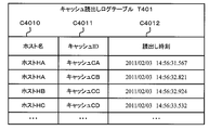
- FIG. 7 shows the column structure of the cache read log table T401.
- the cache read log table T401 includes, for example, a host name column C4010, a cache ID column C4011, and a read time column C4012.
- the host name column C4010 information for identifying each host 10 is stored.
- the cache ID column C4011 information for identifying the cache data 311 read by the host 10 is stored.
- the cache ID is generated as information that is uniquely determined at least within the computer system.
- the cache ID can be generated using a technique such as GUID (Globally Unique Identifier).
- GUID Globally Unique Identifier
- a hash value obtained from the cache data 331 may be used as the cache ID.
- the date and time when the host 10 reads the cache data 311 is stored.
- the record of the cache read log table T401 it is possible to check which host 10 has read which cache data 311 in the cache device 30.
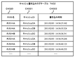
- FIG. 8 shows the column structure of the cache write log table T402.
- the cache write log table T402 includes, for example, a host name column C4020, a cache ID column C4021, and a write time column C4022.
- the host name column C4020 stores information for identifying the host 10.
- the cache ID column C4021 stores information for identifying the cache data 311 written by the host 10.
- the write time column C4022 stores the date and time when the cache data 311 was written by the host 10.
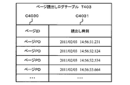
- FIG. 9 shows the column structure of the page read log table T403.
- the page read log table T403 includes, for example, a page ID column C4030 and a read time column C4031.
- the page ID column C4030 stores information for identifying the page 211.
- the read time column C4031 stores the date and time when the page 211 is read.
- FIG. 10 shows the column structure of the page write log table T404.
- the page write log table T404 includes, for example, a logical volume ID column C4040, a page ID column C4041, and a write time column C4042.
- the logical volume ID column C4040 stores information for identifying the logical volume 210.
- a logical volume is abbreviated as a volume.
- the page ID column C4041 stores information for identifying the page 211 in the logical volume 210.
- the write time column C4042 stores the date and time when data was written to the page 211.
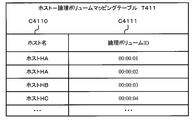
- FIG. 11 is a diagram showing the column structure of the host-logical volume mapping table T411.
- the host-logical volume mapping table T411 includes, for example, a host name column C4110 and a logical volume ID column C4111.
- the host name column C4110 stores information for identifying the host 10.
- the logical volume ID column C4111 stores information for identifying the logical volume 210 used by the host 10.
- FIG. 12 is a diagram showing the column structure of the cache-page mapping table T412.
- the cache-page mapping table T412 includes, for example, a cache ID column C4120 and a page ID column C4121.
- the cache ID column C4120 stores information for identifying the cache data 311.
- the page ID column C4121 stores information for identifying the page 211.
- FIG. 13 is a diagram showing a column structure of the page effective load table T421.
- the page effective load table T421 includes, for example, a page ID column C4210 and an effective total I / O number column C4211.
- the page ID column C4210 stores information for identifying the page 211.
- the effective total I / O number column C4211 stores the number of times the page 211 is actually accessed (the sum of the number of reads and the number of writes).
- the page effective load table T421 is a value obtained by adding the number of I / Os for the page 211 and the number of I / Os for the cache data 311 that holds data having the same contents as the page 211.
- the effective total I / O number can be checked. That is, the table T421 manages the total number of page I / Os in consideration of the number of times read from the cache device 30.
- FIG. 14 is a flowchart showing a processing procedure performed by the device log acquisition unit P40 of the management server 40.
- the step may be abbreviated as “S”.
- the order of the temporal order of the set of S10 and S11, the set of S12 and S13, the set of S14 and S15, and the set of S16 and S17 can be changed.
- the group S16 and S17 may be executed first, then the group S14 and S15 may be executed, the group S12 and S13 may be executed next, and the group S10 and S11 may be executed last.
- the device log acquisition unit P40 analyzes the read / write log D20 in the storage device 20 and acquires information related to the read request of each page 211 (S10). Subsequently, the device log acquisition unit P40 stores the information acquired in S10 in the page read log table T403 (S11).
- the device log acquisition unit P40 analyzes the read / write log D30 in the cache storage unit 330 and acquires information related to the read request for the cache data 331 (S14). Subsequently, the device log acquisition unit P40 stores the information acquired in S14 in the cache read log table T401 (S15).
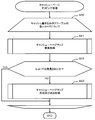
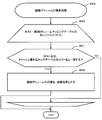
- the cache-page mapping unit P41 executes S21, S22, and S23 for each record in the cache write log table T402 (S20).
- the cache-page mapping unit P41 searches whether the cache data 331 described in the record of the cache write log table T402 is already mapped to any page 211 (S21). That is, the cache-page mapping unit P41 searches the column C4120 of the cache-page mapping table T412 shown in FIG. 12 using the cache ID stored in the column C4021 of the cache write log table T402 shown in FIG. 8 as a search key. .
- the cache-page mapping unit P41 determines whether a record relating to the target cache data 331 exists in the cache-page mapping table T412 (S22). That is, the cache-page mapping unit P41 determines whether or not the cache data (target cache data) described in the record of the cache write log table T402 is registered in the cache-page mapping table T412.
- the cache-page mapping unit P41 newly creates and stores a mapping between the cache data 331 and the page 211.
- the process for performing is performed (S23).
- FIG. 16 is a flowchart showing a detailed processing procedure of the cache-page map search process indicated by S21 in FIG.
- the cache-page mapping unit P41 executes S31 and S32 for each record of the cache-page mapping table T412 (S30).
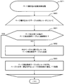
- FIG. 17 is a flowchart showing the detailed processing procedure of the cache-page map creation and addition processing shown in S23 in FIG.
- FIG. 18A shows a method of specifying the correspondence between the cache data 331 and the page 211 based on the update timings Tc1 and Tc2 of the cache data 331 and the update timing Tp of the page 211.
- the application program 11 first updates the data in the page 211 and then updates the cache data 331.
- the latest write time Tc2 and the previous write time Tc1 are detected for the cache data to be processed (hereinafter, the target cache data). Further, in this process, a page updated within a predetermined time Tc12 between the latest write time Tc2 of the target cache data and the previous write time Tc1 is detected, and the update time (write time) Tp of the page is detected.
- the page updated within the predetermined time Tc12 is newly associated with the target cache data.
- a new map is created and stored in the cache-page mapping table T412.
- the application program 11 is considered to update the cache data 331 immediately after updating the data of the page 211 first.
- the predetermined time Tc12 from the latest cache write time Tc2 to the previous cache write time Tc1 is used as a period for searching for the correspondence.
- the page 211 that is updated within the predetermined time Tc12 and that is configured by the same host 10 as the update source of the cache data 331 is a page corresponding to the target cache data 331. Is determined.
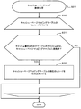
- the cache-page mapping unit P41 acquires the previous write time Tc1 for the target cache data 331 (S40). The cache-page mapping unit P41 determines whether or not the write time Tc1 prior to the latest write time Tc2 has been acquired for the target cache data 331 (S41).
- the cache-page mapping unit P41 searches for the ID of the logical volume used by the host 10 that has written to the target cache data 331. (S42).
- the cache-page mapping unit P41 determines whether or not the write time Tp to the page 211 is within a predetermined time Tc12 from the latest write time Tc2 of the target cache data 331 to the previous write time Tc1 (S44).
- the process moves to the next record. If the write time Tp of the page 211 exists within the predetermined time Tc12 (S44: YES), the cache-page mapping unit P41 matches the ID of the logical volume to which the page 211 belongs and the volume ID searched in S42. It is determined whether or not (S45).
- S45 it is determined whether or not the logical volume used by the host 10 that has updated the target cache data 331 is the same as the logical volume to which the page 211 updated by the host 10 belongs. That is, the cache-page mapping unit P41 determines whether or not the host 10 that is the writing source of the target cache data 331 and the host 10 that is the writing source of the page 211 are the same.
- the cache-page mapping unit P41 registers a set of the target cache data 331 and the page 221 updated by the same host 10 as the target cache data 331 in the cache-page mapping table T412.
- the page 211 and the cache data 331 can be associated with each other based on the update timing.
- the application program 11 may first update the cache data 331 and then update the data in the page 211.
- a method for associating the page 211 with the cache data 331 will be described in an embodiment described later.
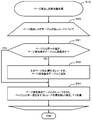
- FIG. 19 is a flowchart of the process for acquiring the previous cache write time indicated by S40 in FIG. S51, S52, S53, S54, and S55 are executed for each record in the cache write log table T402.
- a record to be processed (a record in the cache write log table T402) is referred to as a target record.
- the cache-page mapping unit P41 determines whether or not the cache ID of the search target cache data 331 is equal to the cache ID recorded in the target record (S51). If the cache ID of the cache data 331 to be searched does not match the cache ID in the target record (S51: NO), the process moves to the next record.
- the cache-page mapping unit P41 indicates that the write time of the target record is the write time of the cache data 331 to be searched. It is determined whether it is before (S52).
- the cache-page mapping unit P41 sets the write time in the target record to It is stored as a candidate for the previous cache write time (S55).
- the cache-page mapping unit P41 determines whether or not the host name (C4110) of the target record matches the host name corresponding to the target cache data (S61).
- the host name corresponding to the target cache data is the host name described in the record corresponding to the target cache data among the host names described in the host name column C4020 of the cache write log table T402.
- FIG. 21 is a flowchart showing a processing procedure of the page effective load calculation unit P42 of the management server 40.
- the steps S71, S72, and S73 are not necessarily executed in this order.
- the page effective load calculation process is executed after the cache-page mapping process (FIG. 15).
- the page effective load calculation unit P42 determines, based on the information acquired by the device log acquisition unit P40, and the mapping generated by the cache-page mapping processing unit P41, an effective load to be used as a reference for page relocation for each page. calculate.
- the page effective load calculation unit P42 executes a process of adding the number of writes to the page 211 (S71).
- the page rearrangement time means the time when the page rearrangement instruction process was executed last time.
- the page effective load calculation unit P42 adds up the number of read requests for each page 211 in the storage apparatus 20 that occurred between the previous page rearrangement time and the current time, and updates the page effective load table T421 (S72). .
- the page effective load calculation unit P42 adds up the number of read requests for each cache data 331 in the cache device 30 corresponding to the page that occurred from the previous page rearrangement time to the present time, and updates the page effective load table T421 ( S73).
- FIG. 22 is a flowchart of the page write count addition process indicated by S71 in FIG.
- the page effective load calculation unit P42 executes S81, S82, and S83 for each record in the page write log table T404 (S80). Of the records in the page write log table T404, a record to be processed is called a target record.
- the page effective load calculation unit P42 determines whether the page ID included in the target record is already registered in the page effective load table T421 (S81).
- the page effective load calculation unit P42 When the page ID in the target record is not registered in the page effective load table T421 (S81: NO), the page effective load calculation unit P42 creates a new record including the page ID in the target record, and the new record is created. It adds to page effective load table T421 (S82). Note that 0 is set as the initial value of the total number of executed I / Os (C4211) in the new record.
- the page effective load calculation unit P42 skips S82.
- the page effective load calculation unit P42 executes S91, S92, and S93 for each record in the page read log table T403 (S90).
- a record to be processed among the records in the table T403 is referred to as a target record.
- the page effective load calculation unit P42 determines whether the page ID included in the target record is already registered in the page effective load table T421 (S91).
- the page effective load calculation unit P42 skips S92.
- the page effective load calculation unit P42 increases the value of the effective total I / O number by 1 in the record of the page effective load table T421 having the same page ID as the page ID in the target record (S83).
- a new record may be added to the table T421 after updating the effective total I / O count for all the records in the page effective load table T421.
- FIG. 24 is a flowchart of the page write count addition process S73 indicated by S73 in FIG.
- the page effective load calculation unit P42 calculates the number of times the cache data 331 specified by the cache ID of the target record has been read from the cache device 30 (S101). The page effective load calculation unit P42 can calculate the number of times the cache data is read by checking how many times the cache ID in the target record appears in the cache read log table T401.
- the page effective load calculation unit P42 determines whether a record having the same page ID as the page ID in the target record already exists in the page effective load table T421 (S102).
- the page effective load calculation unit P42 When a record having the same page ID as the page ID in the target record does not exist in the page effective load table T421 (S102: NO), the page effective load calculation unit P42 creates a new record and stores it in the table T421. It is added (S103). The new record has the same page ID as the page ID in the target record. In the effective total I / O number column of the new record, 0 is set as an initial value.
- a new record may be added to the table T421 after updating the effective total I / O count for all the records in the page effective load table T421.
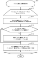
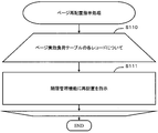
- the page rearrangement instruction unit P43 executes S111 described later for each record in the page effective load table T421 (S110). Of the records in the table T421, a record to be processed is referred to as a target record.
- the page rearrangement instruction unit P43 instructs the tier management function P20 of the storage apparatus 20 to rearrange the page 211 indicated in the target record based on the value of the effective total I / O count.
- FIG. 26 is a screen example of the cache device setting screen G10 displayed on the display 43 by the management server 40.
- the setting screen G10 is a screen for setting information for managing the cache device 30 by the management server 40.
- the cache device setting screen G10 includes, for example, a device type input field GP11, an IP address input field GP12, and a log acquisition interval input field GP13.
- the device type input column GP11 is a column for inputting or selecting the type of the cache device 30 to be managed by the management server 40.
- the IP address input column GP12 is a column for inputting the IP address of the cache device 30.
- the log acquisition interval input column GP13 is a column for inputting a time interval for executing the apparatus log acquisition process. If the type of cache device is preset, the device type input field GP11 can be abolished.
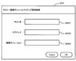
- FIG. 27 is a screen example of the host-logical volume mapping setting screen G20 displayed on the display 43 by the management server 40.
- the setting screen G20 is a screen for setting the logical volume 210 used by the host 10.
- a page including the data can be arranged in an appropriate disk hierarchy 251 according to the actual number of I / Os of the data.
- the management server 40 acquires the data usage status (I / O log D20) in the storage device 20 and the data usage status (I / O log D30) in the cache device 30, and Measure actual usage (effective total I / O count). Therefore, the storage device 20 and the cache device 30 do not need to be aware of each other and do not need to change their configurations so much.
- a second embodiment will be described with reference to FIGS.
- Each of the following embodiments including this embodiment corresponds to a modification of the first embodiment. Accordingly, the following embodiments will be described with a focus on differences from the first embodiment.
- the accuracy of determining the correspondence between the page 211 and the cache data 331 is increased.
- the correspondence between the cache data 331 in the cache device 30 and the page 211 in the storage device 20 is estimated based on past statistical information.
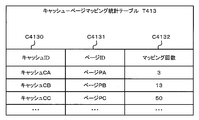
- FIG. 29 shows the configuration of the cache-page mapping statistics table T413.
- the cache-page mapping statistical table T413 manages statistical data of the correspondence relationship between the cache data 331 and the page 211.
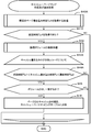
- FIG. 30 is a flowchart of the cache-page mapping process of this embodiment.
- S21 and S22 are abolished compared to the process shown in FIG.
- S21 and S22 are excluded.
- reference numeral S23A is given to the improved process.
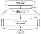
- FIG. 31 is a flowchart of the cache-page map creation and addition process S23A according to this embodiment. This flowchart is different from the flowchart shown in FIG. 17 in that S46 is replaced with S47. In S47, the current page-cache map is estimated based on statistics of past estimation results (determination results).
- the cache-page mapping unit P41 determines whether or not the currently estimated map candidate (target map candidate) is included in the cache-page mapping statistical table T413 (S120).
- the cache-page mapping unit P41 When the target map candidate is not included in the cache-page mapping statistical table T413 (S120: NO), the cache-page mapping unit P41 creates a new record and adds it to the cache-page mapping statistical table T413 (S121). ).
- the new record includes a cache ID and a page ID related to the target map candidate.
- mapping count column C4132 0 is set as an initial value.
- the cache-page mapping unit P41 detects, in the cache-page mapping statistical table T413, a record having the maximum value in the mapping count column C4132 from records having the same cache ID as the cache ID of the target map candidate. . Then, the cache-page mapping unit P41 stores a record having the maximum number of mappings for a predetermined cache ID in the cache-page mapping table T411 as a determination result.
- the correspondence between the cache data 331 and the page 211 can be determined based on the past determination result. Therefore, in this embodiment, the correspondence between the cache data 331 and the page 211 can be determined more accurately, and as a result, the page 211 can be arranged in a more appropriate disk hierarchy.
- a third embodiment will be described with reference to FIG.
- a method for associating cache data with a page when the application program 11 first updates the cache data 331 and then updates the data of the page 211 will be described.
- the first embodiment will be described as a premise, but the present embodiment can be combined with the third embodiment instead.
- the cache-page mapping unit P41 uses a predetermined time Tp12 from the latest page write time Tp2 to the previous page write time Tp1 as a search period.
- Tp12 a predetermined time from the latest page write time Tp2 to the previous page write time Tp1 as a search period.
- S44A, S45, and S46 are executed for each record in the cache write log table T402.
- the cache-page mapping unit P41 determines the ID of the logical volume used by the host 10 that updated the cache data 331, and S42 It is determined whether or not the retrieved volume ID matches (S45).
- This embodiment configured as described above also has the same effect as the first embodiment. Furthermore, this embodiment can also be applied to the case where the cache data 331 is updated first and the page 211 is updated later. Since the application program 11 can update the frequently used cache data 331 first, it can respond promptly to a request from the user terminal.
- the present invention can also be expressed as a computer program or a computer system as follows, for example.
- “Aspect 1. A computer program for causing a computer to function as a management device for managing a computer system including a storage device that provides a logical volume to a host computer and a cache device used by the host computer, In the cache device, a part of data stored in a storage area of a predetermined size in the logical volume is stored as cache data, The computer, Causing the host computer to detect a first access request to the data in the storage area in the logical volume; Causing the host computer to detect a second access request to the cache data in the cache device; Detecting the correspondence between the data in the storage area in the logical volume and the cache data of the cache device; Calculating a total access request to the data in the storage area based on the first access request and the second access request; Computer program.
- a computer system including a host computer, a storage device that provides a logical volume to the host computer, a cache device used by the host computer, the host computer, the storage device, and a management device connected to the cache device Because In the cache device, a part of data stored in a storage area of a predetermined size in the logical volume is stored as cache data,
- the management device includes a microprocessor, a storage device that stores a predetermined computer program used by the microprocessor, and a communication interface circuit for communicating with the host computer and the storage device, The microprocessor executes the predetermined computer program, Detecting a first access request to the data in the storage area in the logical volume by the host computer; Detecting a second access request to the cache data in the cache device by the host computer; Detecting a correspondence relationship between the data in the storage area in the logical volume and the cache data of the cache device; Calculating a total access request to the data in the storage area based on the first access request and the second access request; Computer system.
Landscapes
- Engineering & Computer Science (AREA)
- Theoretical Computer Science (AREA)
- General Engineering & Computer Science (AREA)
- Physics & Mathematics (AREA)
- General Physics & Mathematics (AREA)
- Human Computer Interaction (AREA)
- Computer Hardware Design (AREA)
- Quality & Reliability (AREA)
- Information Retrieval, Db Structures And Fs Structures Therefor (AREA)
- Memory System Of A Hierarchy Structure (AREA)
Abstract
Conformément à la présente invention, lorsqu'un ordinateur hôte utilise conjointement un dispositif de stockage et un dispositif d'antémémoire, la fréquence d'utilisation effective des données est mesurée et la position des données dans le dispositif de stockage est commandée. Une partie des données utilisées par un programme d'application (1A) est stockée dans un dispositif de stockage (2) et un dispositif d'antémémoire (3). Un dispositif de gestion (4) détecte (4A) la charge d'entrée/sortie (I/O) d'une page et détecte en outre (4B) la charge d'entrée/sortie des données d'antémémoire. Le dispositif de gestion (4) détermine (4C) la relation de correspondance entre la page et les données d'antémémoire et ajoute la charge d'entrée/sortie des données d'antémémoire à la charge d'entrée/sortie de la page.
Priority Applications (5)
| Application Number | Priority Date | Filing Date | Title |
|---|---|---|---|
| PCT/JP2011/062412 WO2012164671A1 (fr) | 2011-05-30 | 2011-05-30 | Dispositif de gestion de système informatique et procédé de gestion |
| EP11867022.3A EP2717165A4 (fr) | 2011-05-30 | 2011-05-30 | Dispositif de gestion de système informatique et procédé de gestion |
| US13/378,312 US8667220B2 (en) | 2011-05-30 | 2011-05-30 | Computer system management apparatus and management method |
| JP2013517732A JP5789660B2 (ja) | 2011-05-30 | 2011-05-30 | 計算機システムの管理装置及び管理方法 |
| US14/184,186 US8954682B2 (en) | 2011-05-30 | 2014-02-19 | Computer system management apparatus and management method |
Applications Claiming Priority (1)
| Application Number | Priority Date | Filing Date | Title |
|---|---|---|---|
| PCT/JP2011/062412 WO2012164671A1 (fr) | 2011-05-30 | 2011-05-30 | Dispositif de gestion de système informatique et procédé de gestion |
Related Child Applications (2)
| Application Number | Title | Priority Date | Filing Date |
|---|---|---|---|
| US13/378,312 A-371-Of-International US8667220B2 (en) | 2011-05-30 | 2011-05-30 | Computer system management apparatus and management method |
| US14/184,186 Continuation US8954682B2 (en) | 2011-05-30 | 2014-02-19 | Computer system management apparatus and management method |
Publications (1)
| Publication Number | Publication Date |
|---|---|
| WO2012164671A1 true WO2012164671A1 (fr) | 2012-12-06 |
Family
ID=47258557
Family Applications (1)
| Application Number | Title | Priority Date | Filing Date |
|---|---|---|---|
| PCT/JP2011/062412 WO2012164671A1 (fr) | 2011-05-30 | 2011-05-30 | Dispositif de gestion de système informatique et procédé de gestion |
Country Status (4)
| Country | Link |
|---|---|
| US (2) | US8667220B2 (fr) |
| EP (1) | EP2717165A4 (fr) |
| JP (1) | JP5789660B2 (fr) |
| WO (1) | WO2012164671A1 (fr) |
Cited By (6)
| Publication number | Priority date | Publication date | Assignee | Title |
|---|---|---|---|---|
| JP2015075818A (ja) * | 2013-10-07 | 2015-04-20 | 株式会社日立製作所 | 計算機システム、キャッシュ管理方法及び計算機 |
| JP2015170160A (ja) * | 2014-03-07 | 2015-09-28 | 富士通株式会社 | 情報処理システム,情報処理装置,情報処理プログラム及び情報処理方法 |
| JP2016024469A (ja) * | 2014-07-16 | 2016-02-08 | Necエンジニアリング株式会社 | データ管理システム、データ管理装置、プログラム及びデータ管理方法 |
| JP2020091706A (ja) * | 2018-12-06 | 2020-06-11 | エヌ・ティ・ティ・コミュニケーションズ株式会社 | ストレージ管理装置、方法およびプログラム |
| US11695832B2 (en) | 2018-12-06 | 2023-07-04 | Ntt Communications Corporation | Data search apparatus, and data search method and program thereof, and edge server and program thereof |
| US11886520B2 (en) | 2018-12-06 | 2024-01-30 | Ntt Communications Corporation | Data search apparatus, and data search method and program thereof, and edge server and program thereof |
Families Citing this family (5)
| Publication number | Priority date | Publication date | Assignee | Title |
|---|---|---|---|---|
| JP5817558B2 (ja) * | 2012-01-27 | 2015-11-18 | 富士通株式会社 | 情報処理装置、分散処理システム、キャッシュ管理プログラムおよび分散処理方法 |
| US10341435B2 (en) * | 2012-06-12 | 2019-07-02 | Centurylink Intellectual Property Llc | High performance cloud storage |
| JP6131170B2 (ja) * | 2013-10-29 | 2017-05-17 | 株式会社日立製作所 | 計算機システム、及びデータ配置制御方法 |
| US10445025B2 (en) | 2014-03-18 | 2019-10-15 | Micron Technology, Inc. | Apparatuses and methods having memory tier structure and recursively searching between tiers for address in a translation table where information is only directly transferred between controllers |
| JP6995723B2 (ja) | 2018-09-19 | 2022-01-17 | キオクシア株式会社 | メモリシステム、ストレージシステム、および制御方法 |
Citations (6)
| Publication number | Priority date | Publication date | Assignee | Title |
|---|---|---|---|---|
| JP2000010740A (ja) * | 1998-06-26 | 2000-01-14 | Hitachi Ltd | 階層記憶管理システム |
| JP2006039942A (ja) * | 2004-07-27 | 2006-02-09 | Nec Software Tohoku Ltd | 階層記憶システムにおけるファイル管理装置及びそのファイル管理方法 |
| JP2006301892A (ja) * | 2005-04-20 | 2006-11-02 | Sony Corp | 階層ストレージ管理装置、方法、およびプログラム |
| JP2008009829A (ja) * | 2006-06-30 | 2008-01-17 | Fujitsu Ltd | ストレージ制御プログラム、ストレージ制御装置、ストレージ制御方法 |
| JP2010108341A (ja) | 2008-10-31 | 2010-05-13 | Hitachi Ltd | 階層型ストレージシステム |
| JP2010257094A (ja) | 2009-04-23 | 2010-11-11 | Hitachi Ltd | 階層ストレージ管理システムにおける移動候補ファイルの抽出方法 |
Family Cites Families (9)
| Publication number | Priority date | Publication date | Assignee | Title |
|---|---|---|---|---|
| JP3248176B2 (ja) * | 1994-05-11 | 2002-01-21 | 日本電信電話株式会社 | ライブラリシステム |
| US6092149A (en) * | 1997-05-28 | 2000-07-18 | Western Digital Corporation | Disk drive cache system using a dynamic priority sequential stream of data segments continuously adapted according to prefetched sequential random, and repeating types of accesses |
| US6981005B1 (en) * | 2000-08-24 | 2005-12-27 | Microsoft Corporation | Partial migration of an object to another storage location in a computer system |
| JP2003216460A (ja) * | 2002-01-21 | 2003-07-31 | Hitachi Ltd | 階層ストレージ装置及びその制御装置 |
| US20060101084A1 (en) * | 2004-10-25 | 2006-05-11 | International Business Machines Corporation | Policy based data migration in a hierarchical data storage system |
| JP5141234B2 (ja) * | 2007-12-19 | 2013-02-13 | 日本電気株式会社 | 階層記憶制御装置、階層記憶制御システム及びそれらに用いる階層記憶制御方法及びそのプログラム |
| US8321645B2 (en) * | 2009-04-29 | 2012-11-27 | Netapp, Inc. | Mechanisms for moving data in a hybrid aggregate |
| EP2419817A1 (fr) * | 2009-10-09 | 2012-02-22 | Hitachi, Ltd. | Système de stockage et son procédé de contrôle, mise en uvre de la réaffectation de données en cas d'écart de charge |
| JP5451875B2 (ja) * | 2010-04-30 | 2014-03-26 | 株式会社日立製作所 | 計算機システム及びその記憶制御方法 |
-
2011
- 2011-05-30 US US13/378,312 patent/US8667220B2/en not_active Expired - Fee Related
- 2011-05-30 WO PCT/JP2011/062412 patent/WO2012164671A1/fr active Application Filing
- 2011-05-30 EP EP11867022.3A patent/EP2717165A4/fr not_active Withdrawn
- 2011-05-30 JP JP2013517732A patent/JP5789660B2/ja not_active Expired - Fee Related
-
2014
- 2014-02-19 US US14/184,186 patent/US8954682B2/en not_active Expired - Fee Related
Patent Citations (6)
| Publication number | Priority date | Publication date | Assignee | Title |
|---|---|---|---|---|
| JP2000010740A (ja) * | 1998-06-26 | 2000-01-14 | Hitachi Ltd | 階層記憶管理システム |
| JP2006039942A (ja) * | 2004-07-27 | 2006-02-09 | Nec Software Tohoku Ltd | 階層記憶システムにおけるファイル管理装置及びそのファイル管理方法 |
| JP2006301892A (ja) * | 2005-04-20 | 2006-11-02 | Sony Corp | 階層ストレージ管理装置、方法、およびプログラム |
| JP2008009829A (ja) * | 2006-06-30 | 2008-01-17 | Fujitsu Ltd | ストレージ制御プログラム、ストレージ制御装置、ストレージ制御方法 |
| JP2010108341A (ja) | 2008-10-31 | 2010-05-13 | Hitachi Ltd | 階層型ストレージシステム |
| JP2010257094A (ja) | 2009-04-23 | 2010-11-11 | Hitachi Ltd | 階層ストレージ管理システムにおける移動候補ファイルの抽出方法 |
Non-Patent Citations (1)
| Title |
|---|
| See also references of EP2717165A4 * |
Cited By (9)
| Publication number | Priority date | Publication date | Assignee | Title |
|---|---|---|---|---|
| JP2015075818A (ja) * | 2013-10-07 | 2015-04-20 | 株式会社日立製作所 | 計算機システム、キャッシュ管理方法及び計算機 |
| JP2015170160A (ja) * | 2014-03-07 | 2015-09-28 | 富士通株式会社 | 情報処理システム,情報処理装置,情報処理プログラム及び情報処理方法 |
| US9824025B2 (en) | 2014-03-07 | 2017-11-21 | Fujitsu Limited | Information processing system, information processing device, information processing program and information processing method |
| JP2016024469A (ja) * | 2014-07-16 | 2016-02-08 | Necエンジニアリング株式会社 | データ管理システム、データ管理装置、プログラム及びデータ管理方法 |
| JP2020091706A (ja) * | 2018-12-06 | 2020-06-11 | エヌ・ティ・ティ・コミュニケーションズ株式会社 | ストレージ管理装置、方法およびプログラム |
| WO2020116612A1 (fr) * | 2018-12-06 | 2020-06-11 | エヌ・ティ・ティ・コミュニケーションズ株式会社 | Dispositif, procédé et programme de gestion de stockage |
| JP7175731B2 (ja) | 2018-12-06 | 2022-11-21 | エヌ・ティ・ティ・コミュニケーションズ株式会社 | ストレージ管理装置、方法およびプログラム |
| US11695832B2 (en) | 2018-12-06 | 2023-07-04 | Ntt Communications Corporation | Data search apparatus, and data search method and program thereof, and edge server and program thereof |
| US11886520B2 (en) | 2018-12-06 | 2024-01-30 | Ntt Communications Corporation | Data search apparatus, and data search method and program thereof, and edge server and program thereof |
Also Published As
| Publication number | Publication date |
|---|---|
| US20120317366A1 (en) | 2012-12-13 |
| JPWO2012164671A1 (ja) | 2014-07-31 |
| EP2717165A4 (fr) | 2015-04-22 |
| US8667220B2 (en) | 2014-03-04 |
| US8954682B2 (en) | 2015-02-10 |
| EP2717165A1 (fr) | 2014-04-09 |
| JP5789660B2 (ja) | 2015-10-07 |
| US20140173194A1 (en) | 2014-06-19 |
Similar Documents
| Publication | Publication Date | Title |
|---|---|---|
| JP5789660B2 (ja) | 計算機システムの管理装置及び管理方法 | |
| US20210182166A1 (en) | Zoned namespace management of non-volatile storage devices | |
| JP4990322B2 (ja) | データ移動管理装置及び情報処理システム | |
| US9747036B2 (en) | Tiered storage device providing for migration of prioritized application specific data responsive to frequently referenced data | |
| US9684593B1 (en) | Techniques using an encryption tier property with application hinting and I/O tagging | |
| US9507720B2 (en) | Block storage-based data processing methods, apparatus, and systems | |
| JP4749140B2 (ja) | データマイグレーション方法及びシステム | |
| US7549016B2 (en) | Storage control apparatus for selecting storage media based on a user-specified performance requirement | |
| JP4843604B2 (ja) | データ・ストレージ装置からデータ・ストレージ装置特有情報を得るための方法及びシステム | |
| JP5657801B2 (ja) | ストレージシステムおよび記憶制御方法 | |
| US9612758B1 (en) | Performing a pre-warm-up procedure via intelligently forecasting as to when a host computer will access certain host data | |
| WO2013072978A1 (fr) | Ordinateur, procédé de déploiement de machine virtuelle, et programme | |
| US20090300283A1 (en) | Method and apparatus for dissolving hot spots in storage systems | |
| US7139871B2 (en) | Method of managing storage system to be managed by multiple managers | |
| JP2007156597A (ja) | ストレージ装置 | |
| US9330009B1 (en) | Managing data storage | |
| US20080276061A1 (en) | Method and computer for determining storage device | |
| US20030233382A1 (en) | Information processing method and system | |
| US8949559B2 (en) | Storage system and performance management method of storage system | |
| JP2018197933A (ja) | ストレージ制御装置、情報処理システムおよびプログラム | |
| WO2019071699A1 (fr) | Procédé de traitement de demande d'e/s, réseau de stockage et hôte | |
| US11461250B2 (en) | Tuning data storage equipment based on comparing observed I/O statistics with expected I/O statistics which are defined by operating settings that control operation | |
| TW202134880A (zh) | 用以進行全快閃記憶體陣列伺服器的資料存取管理的方法與設備 | |
| JP7017546B2 (ja) | ストレージシステム、パス管理方法、及びパス管理プログラム | |
| JP2009294699A (ja) | ストレージ装置 |
Legal Events
| Date | Code | Title | Description |
|---|---|---|---|
| WWE | Wipo information: entry into national phase |
Ref document number: 13378312 Country of ref document: US |
|
| 121 | Ep: the epo has been informed by wipo that ep was designated in this application |
Ref document number: 11867022 Country of ref document: EP Kind code of ref document: A1 |
|
| ENP | Entry into the national phase |
Ref document number: 2013517732 Country of ref document: JP Kind code of ref document: A |
|
| NENP | Non-entry into the national phase |
Ref country code: DE |