WO2012161197A1 - 被破壊センサ - Google Patents
被破壊センサ Download PDFInfo
- Publication number
- WO2012161197A1 WO2012161197A1 PCT/JP2012/063087 JP2012063087W WO2012161197A1 WO 2012161197 A1 WO2012161197 A1 WO 2012161197A1 JP 2012063087 W JP2012063087 W JP 2012063087W WO 2012161197 A1 WO2012161197 A1 WO 2012161197A1
- Authority
- WO
- WIPO (PCT)
- Prior art keywords
- destroyed
- broken
- cover member
- pair
- sensor
- Prior art date
- Legal status (The legal status is an assumption and is not a legal conclusion. Google has not performed a legal analysis and makes no representation as to the accuracy of the status listed.)
- Ceased
Links
Images
















Classifications
-
- G—PHYSICS
- G01—MEASURING; TESTING
- G01B—MEASURING LENGTH, THICKNESS OR SIMILAR LINEAR DIMENSIONS; MEASURING ANGLES; MEASURING AREAS; MEASURING IRREGULARITIES OF SURFACES OR CONTOURS
- G01B1/00—Measuring instruments characterised by the selection of material therefor
-
- G—PHYSICS
- G01—MEASURING; TESTING
- G01B—MEASURING LENGTH, THICKNESS OR SIMILAR LINEAR DIMENSIONS; MEASURING ANGLES; MEASURING AREAS; MEASURING IRREGULARITIES OF SURFACES OR CONTOURS
- G01B7/00—Measuring arrangements characterised by the use of electric or magnetic techniques
- G01B7/16—Measuring arrangements characterised by the use of electric or magnetic techniques for measuring the deformation in a solid, e.g. by resistance strain gauge
- G01B7/18—Measuring arrangements characterised by the use of electric or magnetic techniques for measuring the deformation in a solid, e.g. by resistance strain gauge using change in resistance
-
- G—PHYSICS
- G01—MEASURING; TESTING
- G01L—MEASURING FORCE, STRESS, TORQUE, WORK, MECHANICAL POWER, MECHANICAL EFFICIENCY, OR FLUID PRESSURE
- G01L1/00—Measuring force or stress, in general
- G01L1/20—Measuring force or stress, in general by measuring variations in ohmic resistance of solid materials or of electrically-conductive fluids; by making use of electrokinetic cells, i.e. liquid-containing cells wherein an electrical potential is produced or varied upon the application of stress
Definitions
- the present invention relates to a destructive sensor that detects deformation of a detection target by being destructed.
- Patent Document 1 discloses a method for detecting breakage of a window glass.
- a conductive wire is attached to the surface on the indoor side of the window glass in a writing-like manner centering on the lock. When the window glass is broken, the conductive wire breaks. According to the failure detection method described in the same document, the failure of the window glass is detected based on the disconnection.
- the conductive wire is linear. For this reason, it is easy to generate a detection leak. That is, when the portion of the window glass where the conductive wire is not disposed is broken, the conductive wire is not broken. In this case, breakage of the window glass can not be detected. Further, according to the failure detection method described in the same document, the conductive wire is directly stuck to the window glass. For this reason, it is difficult to selectively destroy only the conductive wire independently of the window glass. Therefore, it is difficult to detect the deformation of the window glass which does not lead to destruction. Moreover, the breakage of the conductive wire, that is, the detection sensitivity is governed by the fragility of the window glass itself. For this reason, it is difficult to adjust the detection sensitivity.
- the to-be-broken sensor of the present invention is completed in view of the above-mentioned subject.
- An object of the present invention is to provide a destructive sensor capable of detecting deformation of an object to be detected that does not easily cause detection failure and does not lead to destruction and to easily adjust detection sensitivity.
- the senor to be destroyed of the present invention is provided with a member to be destroyed which has a portion to be destroyed which has brittleness, and detects deformation of a detection object based on destruction of the portion to be destroyed. It is characterized by
- the “deformation” of the detection target also includes the displacement (movement) of the detection target.
- the “brittleness” of the portion to be broken refers to the same brittleness as that of glass, ceramics, etc., which is generally referred to as a brittle material.
- the portion to be destroyed is brittle. For this reason, the stroke required for destruction of a to-be-destructed part may be short. Therefore, the thickness in the load transfer direction of the sensor to be destroyed can be reduced. Moreover, since the to-be-broken portion has brittleness, the to-be-broken portion is rapidly broken by the load applied by the deformation of the detection target. Therefore, the response delay of the destructive sensor to the actual deformation is reduced. In addition, since the portion to be destroyed has brittleness, it is possible to detect not only the deformation of the object to be destroyed but also the deformation which does not lead to the destruction.
- the detection sensitivity can be freely adjusted by adjusting the fragility of the portion to be destroyed. For example, when the portion to be destroyed is easily broken, deformation can be detected even if the amount of deformation of the detection target is small. That is, the detection sensitivity is increased. If the portion to be destroyed is hard to break, deformation can be detected when the amount of deformation of the detection target is large. That is, the detection sensitivity is lowered.
- the portion to be broken is disposed to face the mounting member, the base material is a resin, and has brittleness and conductivity, and the member to be broken is And a plurality of support portions interposed between the damaged portion and the attachment member and securing a stroke when the broken portion is broken between the attachment member and the damaged portion.
- the deformation of the object to be detected is detected on the basis of the change in the electric resistance before and after the destruction.
- the base material of the portion to be destroyed is a resin. Therefore, the degree of freedom for the shape of the portion to be destroyed is high. Therefore, it is possible to easily manufacture a band-like or planar broken portion as well as a linear one. By arranging a band-like or planar broken portion on the detection target, deformation of the detection target can be detected over a wide area. For this reason, it becomes difficult to generate a detection leak.
- the damage sensor of this configuration includes a plurality of support portions.
- the plurality of support portions support the broken portion in a floating state with respect to the attachment member. Therefore, it is possible to secure a stroke necessary for breaking the to-be-broken portion between the mounting member and the to-be-broken portion.
- the to-be-broken-up portion is preferably configured to be interposed between the attachment member and the pressing member facing the attachment member. According to this configuration, it is possible to destroy the to-be-broken part by utilizing the fact that the distance between the mounting member and the pressing member is reduced.
- the to-be-broken member includes a single-piece to-be-broken body having at least one of a plurality of the support portions and the to-be-broken portion. It is better.
- the number of parts is reduced as compared to the case where all the support parts are separate from the parts to be destroyed.
- the number of assembling steps of the destruction sensor can be reduced.
- the manufacturing cost of the sensor to be destroyed can be reduced.
- At least one of the plurality of support portions is a terminal that outputs an electric quantity related to the electric resistance of the portion to be broken. It is better.
- the terminal can be used as a support. For this reason, compared with the case where a terminal is not used as a support part, a number of parts decreases. In addition, the manufacturing cost of the sensor to be destroyed can be reduced.
- the terminal is less brittle than the portion to be broken, and the portion to be broken is attached to the mounting member through the terminal. Good.
- the to-be-broken part is attached to the attachment member via the terminal.
- the terminal for example, metal
- the terminal is less brittle than the portion to be broken. That is, it is hard to break even if it is deformed. For this reason, when attaching a to-be-broken sensor to an attachment member, it can suppress that distortion remains in a to-be-broken part by a terminal deform
- the support portions other than the terminals float from the mounting member before a load is input from the outside, and the load is input. It is better to be in contact with the mounting member. According to this configuration, the vibration from the mounting member is less likely to be transmitted to the to-be-destructed portion via the support portion.
- the direction in which the load is transmitted to the portion to be broken is the load transmission direction
- the direction orthogonal to the load transmission direction is the orthogonal direction.
- the member to be broken has a wave plate shape in which the wavelength direction is the orthogonal direction and the amplitude direction is the load transfer direction, and at least one of the plurality of support portions is disposed at the top of the amplitude of the member to be broken It is better to have a configuration that According to this configuration, the support portion and the portion to be destroyed are disposed by utilizing the shape (wave plate shape) of the member to be destroyed.
- the portion to be destroyed has a notch which induces its own destruction. According to this configuration, the portion to be destroyed is easily broken. Therefore, even if the amount of deformation of the detection target is small, the deformation can be detected. That is, the detection sensitivity is increased. Further, the fracture site in the to-be-destructed portion can be guided to the vicinity of the notch. For this reason, the variation in detection sensitivity is reduced among the plurality of sensors to be destroyed. In addition, in the case where a plurality of portions to be destroyed are arranged, variation in detection sensitivity is reduced among the plurality of portions to be destroyed.
- the portion to be destroyed preferably has a conductive filler to be filled in the base material.
- the brittleness and conductivity of the portion to be broken can be adjusted by the shape, size, filling amount and the like of the conductive filler.
- the breaking elongation of the portion to be broken is preferably 5% or less.
- the reason for setting the breaking elongation to 5% or less is that when it exceeds 5%, it is difficult to obtain desired brittleness. In order to obtain higher brittleness, it is better to set the breaking elongation of the portion to be broken to 1% or less.
- the member to be broken includes a cover member disposed on the front side of the portion to be broken, and the cover member is a member to be broken A pair of cover member side attachment parts attached to the part and spaced apart by a predetermined distance in a surface direction of the part to be broken, and a surface of the part to be broken disposed between the pair of cover member side attachment parts And a cover member side connecting portion connecting the pair of the cover member side mounting portion and the cover member side protruding portion. It is better to
- the load is transmitted from the cover member side protruding portion to the pair of cover member side mounting portions via the pair of cover member side connecting portions. For this reason, a load acts on the portion to be broken so as to be spread outward in the surface direction. Therefore, there is little possibility that the fragments of the portion to be destroyed once separated will be connected again. In other words, there is little possibility that the sensor to be destroyed which has once switched from the conductive state to the insulating state will switch from the insulating state to the conductive state again. For this reason, it is possible to suppress the occurrence of the detection omission with respect to the deformation of the detection target.
- the pair of support portions is disposed on both sides in the surface direction of the portion to be broken, and the pair of cover member side attachment portions is a pair of support portions.
- the load is transmitted from the cover member side protruding portion to the pair of cover member side attachment portions via the pair of cover member side connection portions, which are disposed on the inner side in the surface direction, and thereby the pair of cover members
- the side attachment portion may be configured to press the pair of support portions outward in the surface direction.
- the load is transmitted from the cover member side protruding portion to the pair of cover member side mounting portions via the pair of cover member side connecting portions.
- the pair of cover member side attachment portions press the pair of support portions outward in the surface direction. For this reason, a load acts on the portion to be destroyed via the pair of support portions so as to be spread outward in the surface direction. Therefore, there is little possibility that the fragments of the portion to be destroyed once separated will be connected again.
- the cover member may have a protrusion that protrudes from the back surface of the cover member side protrusion to the back side.
- the load is transmitted in the front and back direction from the cover member side protruding portion to the portion to be broken via the projection.
- the load is transmitted in the surface direction from the cover member side protruding portion to the portion to be broken via the pair of cover member side connecting portions. That is, the input load can be divided into the front and back direction component force and the surface direction component force and transmitted to the portion to be destroyed. For this reason, the to-be-destructed part can be easily destroyed and separated.
- the cover member preferably has an insulating property. According to this configuration, it is possible to ensure the insulation of the portion to be destroyed relative to the outside. In particular, in the case where the present configuration and the configuration of the above (11) are combined, it is possible to suppress the reconnection of the fragments by interposing the projection between the fragments of the portion to be destroyed once separated.
- connection portion of at least one of the plurality of fixtures has a low rigidity portion that is lower in rigidity than the broken portion.
- the "attachment target member" in the present configuration corresponds to the "attachment member" of the configuration of the above (2).
- the sensor to be destroyed of the present invention has a fragile (brittle) portion to be broken. According to this damage sensor, the detection sensitivity can be adjusted by adjusting the fragility of the damage portion. Moreover, even if it is deformation of the detection object that does not lead to destruction, the deformation can be detected by adjusting the detection sensitivity so that only the to-be-destructed part is selectively broken by the deformation. If the destroyed part is destroyed, the destroyed sensor can not be used. That is, the sensor to be destroyed can be used only once. For this reason, it is not preferable that the portion to be destroyed is destroyed by a factor other than the deformation of the detection object.
- the target sensor is mounted in a state in which distortion occurs in the target portion due to dimensional error of the target sensor (difference between the design shape and the actual shape) and dimensional error of the mounting target member to which the target sensor is attached. It may be attached to a member. In this case, there is a possibility that the portion to be broken may be broken by the stress caused by the strain.
- the present configuration at least a part of the strain generated in the to-be-broken portion when the to-be-broken sensor is attached to the mounting target member can be absorbed by the low rigidity portion of the fixture. For this reason, there is little possibility that the portion to be broken may be broken by the stress caused by the strain.
- the portion to be destroyed preferably has a notch that induces its own destruction.
- the portion to be destroyed is easily broken. Therefore, even if the amount of deformation of the detection target is small, the deformation can be detected. That is, the detection sensitivity is increased. Further, the fracture site in the to-be-destructed portion can be guided to the vicinity of the notch. For this reason, the variation in detection sensitivity is reduced among the plurality of sensors to be destroyed. Further, in the case where a plurality of parts to be destroyed are arranged in a single sensor to be destroyed, variation in detection sensitivity is reduced among the plurality of parts to be destroyed.
- the breaking elongation of the portion to be broken is preferably 5% or less.
- the reason for setting the breaking elongation to 5% or less is that when it exceeds 5%, it is difficult to obtain desired brittleness. In order to obtain higher brittleness, it is better to set the breaking elongation of the portion to be broken to 1% or less.
- the member to be broken is provided so as to protrude from the portion to be broken toward the member to be attached, and the portion to be broken is broken between the member to be attached and It is better to have a configuration that has a support for securing a stroke when moving.
- the portion to be broken When the object to be detected is deformed, if the low rigidity portion is deformed, there is a possibility that the portion to be broken may be hardly broken. For this reason, detection accuracy is reduced.
- the stroke when the portion to be destroyed is broken is secured by the support portion. Therefore, regardless of the presence or absence of the deformation of the low rigidity portion and the degree of the deformation, the portion to be broken can be destroyed by the deformation of the detection target. Therefore, detection accuracy is improved.
- the member to be destroyed preferably includes an object to be destroyed which is an integral body including the portion to be broken and the support portion. According to this configuration, the number of parts of the member to be destroyed is reduced.
- the connecting portion extends in a direction intersecting with a protruding portion protruding from the mounting portion toward the load input side and the protruding portion It is better to have an extension portion, and the extension portion is configured to have the low rigidity portion.
- the low rigidity portion When the low rigidity portion is disposed in the projecting portion (however, this case is also included in the configuration of the above (13)), the rigidity in the load input direction of the broken sensor is lowered. In this respect, according to the present configuration, the low rigidity portion is disposed not in the projecting portion but in the extending portion. For this reason, the rigidity in the load input direction of the destructive sensor is unlikely to be reduced.
- the low rigidity portion is a bent portion which is bent with respect to a straight line connecting the protrusion side end of the extension and the fixing side. It is better to use
- the rigidity can be adjusted by bending with respect to a straight line connecting the protrusion-side end of the extension and the fixing-part-side end. That is, the rigidity of the bent portion can be lowered by arranging the bent portion in the extending portion.
- the low rigidity portion has a cross-sectional area in a direction orthogonal to the extending direction of the connection portion other than the connection portion. It is better to be configured to be a small cross-sectional area smaller than the part. According to this configuration, the rigidity can be adjusted by the cross-sectional area. That is, the rigidity of the small cross-sectional area can be reduced by arranging the small cross-sectional area in the connecting portion.
- the small cross-sectional area portion has a reduced width in a direction orthogonal to the extending direction of the connecting portion with respect to the other portion of the connecting portion. It is better to have a configuration that is a narrow part. According to this configuration, the torsional rigidity and the bending rigidity of the constricted portion can be reduced.
- the small cross-sectional area portion is a hollow portion having a through hole penetrating the connection portion. According to this configuration, the torsional rigidity and bending rigidity of the hollow portion can be reduced.
- the portion to be broken has conductivity, and a pair of the plurality of fixtures among the plurality of fixtures are broken. It is better to be a structure which is a pair of terminals which outputs the electric quantity regarding destruction of a part. According to this configuration, the fixture and the terminal are shared. For this reason, the number of parts of the sensor to be destroyed is reduced.
- the portion to be destroyed has a resin base material and a conductive filler filled in the base material.
- the conductivity of the portion to be destroyed can be secured by the conductive filler.
- the conductivity can be adjusted by the filling ratio of the conductive filler to the base material.
- the pair of terminals are disposed at both ends in the longitudinal direction of the member to be broken, and the fixing portions of the terminal are embedded in the member to be broken, A buried portion extending in a direction intersecting the longitudinal direction and having the longitudinally outward facing surface, and a longitudinally inward facing surface extending in the direction intersecting the longitudinal direction. It is better to have a configuration.
- the member to be destroyed and the terminal may move relatively in the longitudinal direction due to the temperature change. In this case, it is difficult to secure conduction between the member to be destroyed and the terminal.
- the embedded portion of the fixed portion has the outward surface and the inward surface. For this reason, even in the case where the member to be broken and the fixture move relatively in the longitudinal direction, at least one of the outward surface and the inward surface secures conduction between the member to be broken and the terminal. be able to.
- the buried portion is buried in the member to be destroyed. For this reason, the meat portion of the member to be destroyed is disposed on the outside in the longitudinal direction of the outward surface. Therefore, the embedded portion is less likely to drop out of the member to be destroyed in the longitudinal direction. As described above, according to the present configuration, it is possible to suppress separation of the terminal and the member to be broken in the longitudinal direction by the anchor effect of the embedded portion.
- the pair of terminals are disposed at both ends in the longitudinal direction of the member to be broken, and the pair of terminals are in the direction of length on the member to be broken It is better to be configured to be attached to the mounting target member in a state in which a compressive load is applied from both sides.
- the member to be destroyed may move inward in the longitudinal direction. In this case, it is difficult to secure conduction between the member to be destroyed and the terminal.
- the pair of terminals is attached to the mounting target member in a state where a compressive load is applied to the member to be broken from both sides in the longitudinal direction. Therefore, even if the member to be broken moves inward in the longitudinal direction with respect to the terminal due to the temperature change, the terminal can follow the movement. Therefore, the conduction between the member to be destroyed and the terminal can be secured.
- the member to be broken includes a cover member disposed on the front side of the portion to be broken, and the cover member is a member to be broken A pair of cover member side attachment parts attached to the part and spaced apart by a predetermined distance in a surface direction of the part to be broken, and a surface of the part to be broken disposed between the pair of cover member side attachment parts And a cover member side connecting portion connecting the pair of the cover member side mounting portion and the cover member side protruding portion. It is better to
- the load is transmitted from the cover member side protruding portion to the pair of cover member side mounting portions via the pair of cover member side connecting portions. For this reason, a load acts on the portion to be broken so as to be spread outward in the surface direction. Therefore, there is little possibility that the fragments of the portion to be destroyed once separated will be connected again. In other words, there is little possibility that the sensor to be destroyed which has once switched from the conductive state to the insulating state will switch from the insulating state to the conductive state again. For this reason, it is possible to suppress the occurrence of the detection omission with respect to the deformation of the detection target.
- the pair of support portions is disposed on both sides in the surface direction of the portion to be broken, and the pair of cover member side attachment portions is a pair of support portions.
- the load is transmitted from the cover member side protruding portion to the pair of cover member side attachment portions via the pair of cover member side connection portions, which are disposed on the inner side in the surface direction, and thereby the pair of cover members
- the side attachment portion may be configured to press the pair of support portions outward in the surface direction.
- the load is transmitted from the cover member side protruding portion to the pair of cover member side mounting portions via the pair of cover member side connecting portions.
- the pair of cover member side attachment portions press the pair of support portions outward in the surface direction. For this reason, a load acts on the portion to be destroyed via the pair of support portions so as to be spread outward in the surface direction. Therefore, there is little possibility that the fragments of the portion to be destroyed once separated will be connected again.
- the cover member may have a projection that protrudes from the back surface of the cover member side protrusion to the back side.
- the load is transmitted in the front and back direction from the cover member side protruding portion to the portion to be broken via the projection.
- the load is transmitted in the surface direction from the cover member side protruding portion to the portion to be broken via the pair of cover member side connecting portions. That is, the input load can be divided into the front and back direction component force and the surface direction component force and transmitted to the portion to be destroyed. For this reason, the to-be-destructed part can be easily destroyed and separated.
- the cover member preferably has an insulating property. According to this configuration, it is possible to ensure the insulation of the portion to be destroyed relative to the outside. In particular, in the case where the present configuration and the configuration of the above (23) are combined, it is possible to suppress the reconnection of the fragments by interposing the projection between the fragments of the portion to be destroyed once separated.
- the present invention it is possible to provide a destructive sensor capable of detecting deformation of a detection target that is less likely to cause detection failure and does not lead to destruction, and that can easily adjust detection sensitivity.
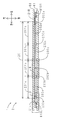
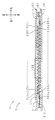
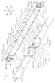
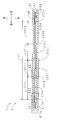
- FIG. 1 is a perspective view of the damage sensor according to the first embodiment.
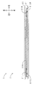
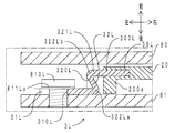
- FIG. 2 is a cross-sectional view of the damage sensor in the left-right direction.
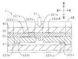
- FIG. 3 is an enlarged view in a frame III of FIG.
- FIG. 4 is an enlarged view in a frame IV of FIG.
- FIG. 5 is a circuit diagram of the same damage sensor.
- FIG. 6 is a cross-sectional view in the left-right direction at the time of load transfer of the broken part of the same broken sensor.
- FIG. 7 is a cross-sectional view in the left-right direction when the destruction of the damaged portion is completed.
- FIG. 8 is a graph showing the relationship between the amount of depression of the broken part and the response voltage of the broken sensor.
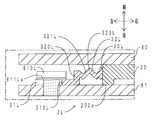
- FIG. 9 is a cross-sectional view in the left-right direction of the sensor to be destroyed in the second embodiment.
- FIG. 10 is an enlarged view within the frame X of FIG.
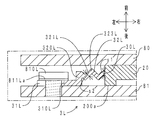
- FIG. 11 is a cross-sectional view in the left-right direction of the damage sensor according to the third embodiment.
- FIG. 12 is an enlarged view within the frame XII of FIG.
- FIG. 13 is a cross-sectional view in the left-right direction of the sensor to be destroyed in the fourth embodiment.
- FIG. 14 is a cross-sectional view in the left-right direction of the sensor to be destroyed in the fifth embodiment.
- FIG. 15 is a perspective view of the broken sensor according to the sixth embodiment.
- FIG. 16 is a cross-sectional view of the damage sensor in the left-right direction.
- FIG. 17 is an enlarged view in a frame XVII of FIG.
- FIG. 18 is an enlarged view of the portion shown in FIG. 17 after destruction.
- FIG. 19 is a perspective view of the sensor to be destroyed according to the seventh embodiment.
- FIG. 20 is a left-right direction cross-sectional view of the same damage sensor.
- FIG. 21 is an enlarged view in a frame XXI of FIG.
- FIG. 22 is an enlarged view in a frame XXII of FIG.
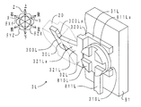
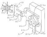
- FIG. 23 is a transparent perspective view of the vicinity of the left terminal of the damage sensor.
- FIG. 24 is a cross-sectional view in the left-right direction at the time of destruction of the portion to be destroyed of the same destruction sensor.
- FIG. 25 is a transparent perspective view in the deformed state in the vicinity of the left terminal of the sensor to be destroyed.
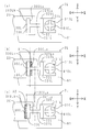
- FIG. 26A is a transparent front view in the reference state near the terminal on the left side of the sensor to be destroyed.
- FIG. 26 (b) is a transparent front view in an expanded state near the same terminal.
- FIG. 26 (c) is a transparent front view in the contracted state near the same terminal.
- FIG. 27 is a transparent perspective view of the vicinity of the terminal on the left side of the sensor to be destroyed according to the eighth embodiment.
- FIG. 28 is a cross-sectional view in the left-right direction near the left terminal of the sensor to be destroyed according to the ninth embodiment.
- FIG. 29 is a cross-sectional view in the left-right direction near the left terminal of the sensor to be destroyed according to the tenth embodiment.
- FIG. 30 is a cross-sectional view in the left-right direction of the vicinity of the left terminal of the sensor to be destroyed according to the eleventh embodiment.
- FIG. 31 is a transparent front view of the sensor to be destroyed according to a twelfth embodiment.
- FIG. 32 is a transparent perspective view of the vicinity of the terminal on the left side of the sensor to be destroyed according to the thirteenth embodiment.
- FIG. 33 is a transparent perspective view of the vicinity of the terminal on the left side of the sensor to be destroyed according to the fourteenth embodiment.
- FIG. 34 is a transparent perspective view of the vicinity of the terminal on the left side of the sensor to be destroyed according to the fifteenth embodiment.
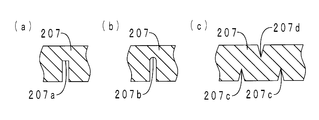
- FIG. 35 is a cross-sectional view of the vicinity of the notch of the sensor to be destroyed.
- FIG. 36 is a cross-sectional view in the left-right direction of another damage sensor (part 1).
- FIG. 37 is a left-right direction cross-sectional view of another damage sensor (part 2).
- 200a to 200e support portions, 201a to 201d: broken portions, 202a to 202d: notches, 203a to 203d: convex portions, 204a to 204v: support portions, 205a to 205u: broken portions, 206: broken portions, 207 A broken part, 207a to 207d: notch, 210L: fixed end, 210La: fixed groove, 211L: embedded end, 220a to 220e: cover member side attachment part, 221b: cover member side protrusion, 221c: cover member Side projection part, 222bL: cover member side connection part, 222bR: cover member side connection part, 222cL: cover member side connection part, 222cR: cover member side connection part, 223b: projection, 223c: projection, 224: base, 300L: Buried portion, 300La: outward surface, 300Lb: inward surface, 310L: mounting groove portion, 320L: projecting portion, 21L: extended portion, 321La: neck
- FIG. 1 shows a perspective view of the sensor to be destroyed in the present embodiment.
- FIG. 2 the left-right direction (longitudinal direction) sectional view of the same damage sensor is shown.
- the front-rear direction front and back direction of the sensor to be destroyed
- the left-right direction corresponds to the “orthogonal direction” of the present invention.
- the sensor 1 to be destructed includes a front (front side) detection object 80 (not shown in FIG. 1) and a rear (back side) attachment target member 81. And is interspersed.
- the mounting target member 81 is included in the concept of the “mounting member” and the “mounting target member” in the present invention.
- the destructive sensor 1 includes the destructive member 2.
- the to-be-destructed member 2 is provided with the to-be-destructed body 20, and the terminals 21L and 21R.
- the to-be-destructed body 20 is exhibiting the flat form extended in the left-right direction as a whole.
- the base material of the to-be-destructed body 20 is an epoxy resin.
- the base material is filled with carbon beads.
- Epoxy resin is included in the concept of "resin” of the present invention.
- Carbon beads are included in the concept of the "conductive filler” of the present invention. Carbon beads are blended at 45% by volume based on 100% by volume of the entire body 20 to be destroyed.
- the to-be-destructed body 20 is an integral part of an injection-molded article.
- the to-be-destructed body 20 is in contact with the rear surface of the detection target 80.
- the to-be-destructed body 20 includes five supporting portions 200a to 200e and four to-be-destructed portions 201a to 201d.
- Each of the support portions 200a to 200e has a prismatic shape.
- the support portions 200 a to 200 e are disposed on the front surface of the mounting object member 81.
- the support portions 200a to 200e are arranged in the left-right direction at predetermined intervals.
- the portions to be destroyed 201a to 201d each have a flat plate shape.
- the destroyed part 201a is between the supporting part 200a and the supporting part 200b
- the destroyed part 201b is between the supporting part 200b and the supporting part 200c
- the destroyed part 201c is between the supporting part 200c and the supporting part 200d.
- the to-be-destructed parts 201d are respectively bridged between the support part 200d and the support part 200e.
- Notches 202a to 202d are recessed at the center of the rear surface of the portions to be destroyed 201a to 201d, respectively.
- FIG. 3 shows an enlarged view within the frame III of FIG.
- the notch 202b is formed in the rear surface of the to-be-destructed part 201b.
- the notch 202 b has a V-shaped groove shape extending in the vertical direction (short direction).
- the shapes of the notches 202a, 202c, and 202d are the same as the shape of the notches 202b.
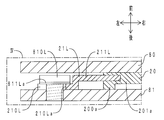
- FIG. 4 shows an enlarged view within the frame IV of FIG.
- the terminal 21L is made of metal and has a plate shape bent in a crank shape as a whole.
- the terminal 21L is disposed at the left end of the body 20 to be destroyed.
- the terminal 21L supports the body 20 to be destroyed. That is, the terminal 21L is included in the concept of the “support portion” in the present invention.
- the terminal 21L includes a fixed end 210L and a buried end 211L.
- a fixed groove portion 210La is formed in the fixed end portion 210L.
- the fixing groove portion 210La has a U-shape opening leftward.
- the screw 810L is inserted into the fixing groove portion 210La.
- the eyeball portion 811La of the wire 811L is annularly mounted on the barrel of the screw 810L (see FIGS. 1 and 4).
- the fixed end portion 210L that is, the terminal 21L is fixed to the front surface of the mounting object member 81 by the screw 810L. Further, the terminal 21L and the wiring 811L are connected by the screw 810L.
- the buried end portion 211L is disposed so as to protrude by one step in the right front direction of the fixed end portion 210L.
- the buried end portion 211 L is partially buried at the left end of the body to be destructed 20.
- the configuration of the terminal 21R is the same as the configuration of the terminal 21L.
- the arrangement of the terminals 21R is symmetrical with the arrangement of the terminals 21L.
- the terminal 21R supports the body 20 to be destroyed. That is, the terminal 21R is included in the concept of the "support portion" in the present invention.
- the terminal 21R is fixed to the mounting object member 81 by the screw 810R. Further, the terminal 21R and the wire 811R are connected by the screw 810R.
- the wires 811L and 811R are electrically connected to a control device (not shown).
- a detection threshold (voltage) is stored in the storage unit of the control device.
- the terminals 21L and 21R and the body to be destroyed 20 are integrated by insert molding. That is, first, the terminals 21L and 21R are disposed in a state where the embedded end portion 211L partially protrudes in the cavity of the injection molding die, and then, the raw material is injected into the cavity and the object to be destructed 20 is injected. By molding, the terminals 21L and 21R and the body 20 are integrated.
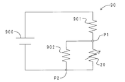
- FIG. 5 shows a circuit diagram of the sensor to be destroyed of the present embodiment.
- the circuit 90 includes a power supply 900, a first resistor 901 and a second resistor 902.
- the circuit 90 is disposed in the controller.
- the electric resistance R1 of the first resistor 901, the electric resistance R2 of the second resistor 902, and the voltage E of the power supply 900 are constant.
- the electric resistance Rt between the detection points P1 and P2 is calculated by the following equation (1), where Rs is the electric resistance between the terminals 21L and 21R (the electric resistance of the body to be destroyed 20).
- Rt (Rs ⁇ R2) / (Rs + R2) ⁇
- the response voltage Vt between the detection points P1 and P2 is calculated by the following equation (2).
- Vt (Rt / (Rt + R1)). E ... Formula (2)
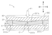
- FIG. 6 shows a cross-sectional view in the left-right direction at the time of load transfer of the broken portion of the broken sensor according to the present embodiment.
- FIG. 7 shows a cross-sectional view in the left-right direction when the destruction of the damaged portion is completed.
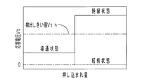
- FIG. 8 is a graph showing the relationship between the amount of depression of the broken part and the response voltage of the broken sensor.
- the portions shown in FIGS. 6 and 7 correspond to the inside of the frame III in FIG.
- the load F1 is input to the detection target 80 from the front.
- the detection target 80 presses the to-be-destructed portion 201 b of the to-be-destructed body 20 from the front.
- the pressed portion 201b is bent so as to expand rearward between the supporting portion 200b and the supporting portion 200c. That is, the to-be-destructed part 201b bends while consuming the stroke S1 secured by the support parts 200b and 200c. Therefore, a tensile force F2 acts in the left-right direction on the rear surface of the to-be-destructed part 201b. Therefore, the load is concentrated at the groove bottom of the notch 202b.
- the body to be destructed 20 is made of an epoxy resin containing carbon beads. For this reason, the to-be-destructed body 20 is fragile. Therefore, due to the load, a crack C1 is generated toward the front at the groove bottom of the notch 202b. When the crack C1 extends to the front surface of the to-be-broken part 201b, as shown in FIG. 7, the to-be-broken part 201b is broken.
- the base material of the destructive object 20 is a resin.
- the freedom with respect to the shape of the to-be-destructed body 20 is high. Therefore, it is possible to easily manufacture the strip-like and planar broken parts 201a to 201d as well as the linear shape.
- the to-be-destructed parts 201a to 201d have a planar shape. Therefore, deformation of the detection target 80 can be detected over a wide area. Therefore, it becomes difficult to generate a detection leak.
- the sensor 1 to be destructed includes supporting portions 200a to 200e.
- the terminals 21L and 21R also play the role of the support portions 200a to 200e.
- the plurality of support parts 200a to 200e and the terminals 21L and 21R support the parts to be destroyed 201a to 201d in a state of being floated forward with respect to the mounting object member 81. For this reason, as shown in FIG. 3, it is possible to secure a stroke S1 necessary for the destruction of the parts to be destroyed 201a to 201d, between the mounting object member 81 and the parts to be destroyed 201a to 201d.
- the portions to be destroyed 201a to 201d are brittle. Specifically, the parts to be destroyed 201 a to 201 d are more brittle than the mounting target member 81. For this reason, the stroke S1 necessary for the destruction of the to-be-destructed parts 201a to 201d may be short. Therefore, the thickness in the front-rear direction of the sensor 1 can be reduced. Further, as shown in FIG. 7, since the parts to be broken 201a to 201d are brittle, the parts to be broken 201a to 201d are rapidly broken by the load F1. Therefore, the response delay of the sensor 1 to actual deformation is reduced. Further, since the portions to be broken 201a to 201d are brittle, not only the deformation of the detection object 80 which leads to destruction but also the deformation which does not lead to destruction can be detected.
- the detection sensitivity can be freely adjusted by adjusting the fragility of the parts to be destroyed 201a to 201d. For example, when the portions to be destroyed 201a to 201d are easily broken, deformation can be detected even if the amount of deformation of the detection target 80 is small. That is, the detection sensitivity is increased. When the portions to be destroyed 201a to 201d are not easily broken, deformation can be detected when the amount of deformation of the detection target 80 is large. That is, the detection sensitivity is lowered.
- the integrated unit 20 is disposed. That is, the support portions 200a to 200e and the portions to be broken 201a to 201d are integrally manufactured by injection molding. For this reason, the number of parts is reduced as compared with the case where the support parts 200a to 200e are separate from the parts to be destroyed 201a to 201d. In addition, the number of assembling steps of the sensor 1 to be destructed can be reduced because joining of the support portions 200a to 200e and the portions 201a to 201d is unnecessary. Moreover, the manufacturing cost of the sensor 1 to be destroyed can be reduced.
- the terminals 21L and 21R and the object to be destructed 20 are integrated by insert molding. That is, bonding of the body to be destructed 20 and the terminals 21L and 21R is performed simultaneously with the formation of the body to be destructed 20. Therefore, the number of manufacturing steps of the sensor 1 to be destroyed can be reduced. Therefore, the manufacturing cost of the sensor 1 to be destroyed can be reduced.
- the terminals 21L and 21R are also used as a support. Therefore, the number of parts is reduced as compared with the case where the terminals 21L and 21R are not used as the support portion. Moreover, the manufacturing cost of the sensor 1 to be destroyed can be reduced.
- the object to be destructed 20 is attached to the mounting object member 81 via the terminals 21L and 21R.
- the terminals 21L and 21R are made of metal. Therefore, the terminals 21L and 21R have higher ductility than the body 20 to be destroyed.
- the destruction target 20 is made of an epoxy resin containing carbon beads. Therefore, the terminals 21L and 21R are less brittle than the body 20 to be destroyed. That is, the terminals 21L and 21R are less likely to be broken even if they are deformed than the to-be-destructed body 20.
- notches 202a to 202d are formed in the portions to be destroyed 201a to 201d, respectively. Therefore, the to-be-destructed portions 201a to 201d are easily broken. Therefore, even when the amount of deformation of the detection target 80 is small, the deformation can be detected. That is, the detection sensitivity is increased.
- the fracture portions in the to-be-destructed portions 201a to 201d can be guided to the vicinity of the notches 202a to 202d. For this reason, the variation in the detection sensitivity is reduced among the plurality of sensors 1 to be destroyed. In addition, the variation in detection sensitivity is reduced among the plurality of destroyed parts 201a to 201d of the single destroyed sensor 1.
- the to-be-destructed body 20 contains the carbon bead. Therefore, the brittleness and conductivity of the portions to be broken 201a to 201d can be adjusted by the shape, size, filling amount and the like of the carbon beads.
- the sensor 1 to be destructed according to this embodiment not only the change from the conduction state to the insulation state, but also the change from the conduction state to the short state can be detected. Therefore, the self-diagnostic property of the sensor 1 to be destroyed is high.
- the tensile force F2 acting on the rear surface (surface opposite to the direction in which the load F1 is input) of the portions 201a to 201d is used.
- the destroyed parts 201a to 201d are destroyed.
- shear force acting between a portion supported by the support portions 200a to 200e from the rear and a portion not supported by the support portions 200a to 200e from the rear among the portions to be destroyed 201a to 201d is made.
- the destroyed parts 201a to 201d are destroyed. Therefore, the to-be-destructed parts 201a to 201d can be destroyed quickly.
- FIG. 9 the left-right direction sectional view of the to-be-broken sensor of this embodiment is shown.
- FIG. 10 shows an enlarged view within the frame X of FIG. In addition, about the site
- convex portions 203a to 203d are integrally formed on the front surfaces of the to-be-destructed portions 201a to 201d of the to-be-destructed body 20, respectively.
- the protrusions 203a to 203d each have a prismatic shape.
- the top surfaces (front surfaces) of the convex portions 203a to 203d abut on the rear surface of the detection target 80, respectively.
- the convex portions 203a to 203d overlap the notches 202a to 202d, respectively.
- the destructive sensor 1 has the same function and effect as the destructive sensor according to the first embodiment with respect to the parts having the same configuration. Further, according to the sensor 1 to be destroyed in the present embodiment, the convex portions 203a to 203d are disposed in front of the notches 202a to 202d. Therefore, the load applied to the detection target 80 can be concentrated in the vicinity of the notches 202a to 202d. In addition, the fracture portion in the to-be-destructed portions 201a to 201d can be guided to the vicinity of the notches 202a to 202d.
- the portion supported by the support portions 200a to 200e from the rear and the portion not supported by the support portions 200a to 200e from the rear The broken parts 201a to 201d are broken by utilizing the shear force acting between the and. Also, use is made of shear force acting between a portion of the to-be-destructed portions 201a to 201d where the convex portions 203a to 203d are disposed forward and a portion where the convex portions 203a to 203d are not disposed forward. As a result, the destroyed parts 201a to 201d are destroyed. Therefore, the to-be-destructed parts 201a to 201d can be destroyed quickly.
- FIG. 11 shows the left-right direction sectional view of the to-be-broken sensor of this embodiment.
- FIG. 12 shows an enlarged view in the frame XII of FIG. In addition, about the site
- the to-be-broken body 20 of the to-be-broken member 2 is in the form of a corrugated plate (specifically, a flat plate extending in the left back-right front direction, and in the left front-right back direction And a zig-zag shape in which a flat plate is alternately connected in the left-right direction.
- the wavelength direction of the to-be-destructed body 20 is the left-right direction.
- the amplitude direction of the to-be-destructed body 20 is the front-rear direction.
- the supports 204 a to 204 v are disposed at the top of the rear of the amplitude of the to-be-destructed body 20.
- the support portions 204a to 204v are in line contact with the front surface of the mounting object member 81, respectively.
- the portions to be destroyed 205a to 205u each have a V shape that is pointed forward.
- the destroyed portions 205a to 205u are respectively disposed between the support portions 204a to 204v adjacent in the left-right direction.
- the V-shaped tops (the tops in front of the amplitude of the body 20 to be destroyed) of the portions 205a to 205u are in line contact with the rear surface of the object to be detected 80, respectively.
- the terminals 21L and 21R each have a flat plate shape. The terminals 21L and 21R do not support the body 20 to be destroyed.
- the destructive sensor 1 according to the present embodiment has the same function and effect as the destructive sensor according to the first embodiment with respect to the parts having the same configuration. Further, according to the sensor 1 of the present embodiment, the support portions 204a to 204v and the portions 205a to 205u are alternately arranged in the left-right direction by using the shape (wave plate shape) of the body 20 to be destroyed. can do.
- V-shaped tops of the parts to be destroyed 205 a to 205 u are in line contact with the rear surface of the detection target 80. Therefore, loads can be concentrated and input to the V-shaped tops of the parts 205a to 205u.
- the support portions 204 a to 204 v are in line contact with the front surface of the mounting object member 81. Therefore, it is possible to intensively input the reaction force of the load applied to the mounting object member 81 from the support portions 204a to 204v to the support portions 204a to 204v.
- the sensor 1 to be destructed is provided with a single portion to be destructed 206.
- the destroyed portion 206 has a flat plate shape extending in the left-right direction.
- the terminal 21 ⁇ / b> L supports the left end of the portion to be destroyed 206.
- the terminal 21R supports the right end of the destroyed portion 206.
- the destructive sensor 1 according to the present embodiment has the same function and effect as the destructive sensor according to the first embodiment with respect to the parts having the same configuration. Moreover, according to the sensor 1 to be destructed according to this embodiment, the stroke necessary for the destruction of the destructible portion 206 can be secured by only the terminals 21L and 21R. For this reason, it is not necessary to arrange a support part in the to-be-destructed part 206 integrally. Therefore, the structure of the destroyed part 206 is simplified.
- the terminals 21L and 21R each have a flat plate shape.
- the terminals 21L and 21R do not support the body 20 to be destroyed.
- the eyeball portion 811La (see FIG. 1) of the wiring is interposed between the terminal 21L and the mounting object member 81.
- the eyeball portion 811La supports the left end of the to-be-destructed portion 206 via the terminal 21L.
- the eyeball portion 811Ra of the wiring is interposed between the terminal 21R and the mounting object member 81.
- the eyeball portion 811Ra supports the right end of the to-be-destructed portion 206 via the terminal 21R.
- the to-be-destructed part 206 is supported by a pair of eyeball parts 811La and 811Ra.
- the destructive sensor 1 of the present embodiment has the same function and effect as the destructive sensor of the fourth embodiment with respect to parts having the same configuration. Moreover, according to the sensor 1 to be destructed of the present embodiment, it is possible to ensure the stroke necessary for the destruction of the destructible portion 206 only by the eyeball portions 811La and 811Ra. For this reason, it is not necessary to arrange a support part in the to-be-destructed part 206 integrally. Moreover, it is not necessary to curve the terminals 21L and 21R in a crank shape.
- FIG. 15 shows a perspective view of the sensor to be destroyed in the present embodiment.
- part corresponding to FIG. 1 it shows with the same code
- the cover member 22 is shown through it.
- the left-right direction (longitudinal direction) sectional view of the same destruction sensor is shown in FIG.
- the parts corresponding to those in FIG. 2 are denoted by the same reference numerals.
- FIG. 17 shows an enlarged view in the frame XVII of FIG. Parts corresponding to those in FIG. 6 are denoted by the same reference numerals.
- a cover member 22 is disposed in front of the to-be-destructed body 20 (front side).
- the cover member 22 is made of polypropylene and has a flat plate shape extending in the left-right direction (plane direction) as a whole.
- the cover member 22 includes a total of twelve cover member side attachment parts 220a to 220e, a pair of left and right cover member side protrusions 221b and 221c, and a total of four cover member side connection parts 222bL, 222bR, 222cL, and 222cR , A pair of left and right protrusions 223b, 223c, and a base portion 224.
- the base portion 224 is in contact with the front surface of the body to be destructed 20.
- a total of twelve cover member side attachment parts 220 a to 220 e are separately disposed at each of the upper and lower edges of the base 224.
- the six cover member side attachment portions 220a to 220e at the upper edge of the base portion 224 and the six cover member side attachment portions 220a to 220e at the lower edge of the base portion 224 are vertically opposed.
- the pair of upper and lower cover member side attachment portions 220a are disposed on the right side of the support portion 200a.
- the pair of upper and lower cover member side attachment portions 220b are disposed on the right side of the support portion 200b.
- the pair of upper and lower cover member side attachment parts 220cL are disposed on the left side of the support part 200c.
- the pair of upper and lower cover member side attachment parts 220cR are disposed on the right side of the support part 200c.
- the pair of upper and lower cover member side attachment parts 220d are disposed on the left side of the support part 200d.
- the pair of upper and lower cover member side attachment parts 220e are disposed on the left side of the support part 200e.
- the rear ends (tips) of the cover member side attachment parts 220a to 220e have a claw shape, respectively.
- the optional pair of upper and lower cover member side attachment parts 220a to 220e sandwich the parts to be destroyed 201a to 201d in the vertical direction.
- the base portion 224, that is, the cover member 22 is detachably attached to the destroyed body 20 by the sandwiching.
- rattling of the cover member 22 with respect to the body to be destroyed 20 is restricted.
- the pair of left and right cover member side protrusions 221 b and 221 c are disposed further to the front than the base portion 224.
- the left cover member side protrusion 221 b and the to-be-destructed portion 201 b are opposed in the front-rear direction.
- the right cover member side protrusion 221c and the to-be-destructed portion 201c are opposed in the front-rear direction.
- a gap is defined between the pair of left and right cover member side protrusions 221b and 221c and the portions to be destroyed 201b and 201c.
- the pair of cover member side connecting portions 222bL and 222bR on the left side are disposed on the left and right sides of the cover member side projecting portion 221b.
- the cover member side connecting portion 222bL connects the cover member side protruding portion 221b and the pair of upper and lower cover member side mounting portions 220b (the base portion 224).
- the cover member side connecting portion 222bR connects the cover member side protruding portion 221b and the pair of upper and lower cover member side mounting portions 220cL (the base portion 224).
- the pair of cover member side connecting portions 222cL and 222cR on the right side are disposed on the left and right sides of the cover member side projecting portion 221c.
- the cover member side connecting portion 222cL connects the cover member side protruding portion 221c and the pair of upper and lower cover member side mounting portions 220cR (the base portion 224).
- the cover member side connecting portion 222cR connects the cover member side protruding portion 221c and the pair of upper and lower cover member side mounting portions 220d (base portion 224).
- the protrusion 223b on the left side is provided so as to protrude from the rear surface (rear surface) of the cover member side protrusion 221b.
- the rear end of the protrusion 223b is in contact with the front surface of the to-be-destructed portion 201b.
- a notch 202b is disposed behind the protrusion 223b.
- the protrusion 223c on the right side is provided so as to protrude from the rear surface (rear surface) of the cover member side protrusion 221c.
- the rear end of the projection 223c is in contact with the front surface of the to-be-destructed portion 201c.
- a notch 202c is disposed behind the protrusion 223c.
- the case where a load is applied to the cover member side protrusion 221 b shown in FIG. 15 will be described.
- the load F1 is input to the detection target 80 from the front.
- the cover member side protrusion 221b applies a load f1 from the front to the to-be-destructed part 201b via the protrusion 223b.
- the cover member side protrusion 221b is provided at the left end portion of the support portion 200b and the to-be-broken portion 201b from the right side via the cover member side connection portion 222bL on the left and the pair of upper and lower cover member side mounts 220b on the left.
- Add a load f2L is provided at the right end portion of the support portion 200c and the to-be-broken portion 201b from the left side via the cover member side connecting portion 222bR on the right side and the pair of upper and lower cover member side mounting portions 220cL on the right side.
- Add a load f2R That is, the load f1 acts to push the notch 202b from the groove bottom side. Also, the loads f2L and f2R act to pull the notch 202b from the left and right direction.
- FIG. 18 shows an enlarged view after destruction of the portion shown in FIG.
- the to-be-destructed part 201 b divides the notch 202 b as a starting point by the load F 1.
- Protrusions 223b intervene between fragments of the to-be-destructed part 201b.
- the distance between the support portion 200b and the support portion 200c is expanded in the left-right direction by the pair of upper and lower cover member side attachment portions 220b and the pair of upper and lower cover member side attachment portions 220cL.
- the destructive sensor 1 according to the present embodiment has the same function and effect as the destructive sensor according to the first embodiment with respect to the parts having the same configuration. Further, according to the sensor 1 of the present embodiment, the load is transmitted from the cover member side protruding portion 221b to the two pairs of cover member side mounting portions 220b and 220cL via the pair of cover member side connecting portions 222bL and 222bR. Be done. For this reason, a load acts on the to-be-destructed part 201b so as to be spread outward in the left-right direction. Therefore, there is little possibility that the fragments of the to-be-destructed part 201b once separated may be connected again.
- the pair of support portions 200b and 200c are disposed on both sides in the left-right direction of the portion to be destructed 201b.
- the two pairs of cover member side attachment parts 220b and 220cL are disposed on the inner side in the left-right direction of the pair of support parts 200b and 200c.
- the projection 223b is interposed between the cover member side protrusion 221b and the portion to be destructed 201b. Therefore, the load F1 can be divided into the load (front and rear direction component) f1 and the loads (left and right direction component) f2L and f2R, and can be transmitted to the portion to be destroyed 201b. Therefore, the to-be-destructed part 201b can be easily destroyed and separated.
- the cover member 22 has insulation. For this reason, the insulation of the to-be-broken part 201b with respect to the detection target object 80 is securable. Further, the protrusion 223b intervenes between the fragments of the portion to be destroyed 201b which has been separated once, so that the fragments can be inhibited from rejoining.
- the protrusion 223b and the notch 202b, and the protrusion 223c and the notch 202c respectively face in the front-rear direction. Therefore, it is easy to concentrate the load on the notches 202b and 202c. Therefore, it is easy to generate a crack on the basis of notches 202b and 202c.
- FIG. 19 shows a perspective view of the sensor to be destroyed in the present embodiment.
- FIG. 20 shows a cross-sectional view of the damage sensor in the left-right direction (longitudinal direction).
- the destructive sensor 1 of the present embodiment is located between the front detection target 80 (not shown in FIG. 19) and the rear attachment target member 81. It is interspersed.
- the destructive sensor 1 includes a destructive member 2 and a pair of left and right terminals 3L and 3R.
- the to-be-destructed member 2 includes a to-be-destructed body 20.
- the to-be-destructed body 20 is exhibiting the flat form extended in the left-right direction as a whole.
- the base material of the to-be-destructed body 20 is an epoxy resin.
- the base material is filled with carbon beads. Carbon beads are blended at 45% by volume based on 100% by volume of the entire body 20 to be destroyed.
- the to-be-destructed body 20 is an integral part of an injection-molded article.
- the to-be-destructed body 20 is in contact with the rear surface of the detection target 80.
- the to-be-destructed body 20 includes five supporting portions 200a to 200e and four to-be-destructed portions 201a to 201d.
- Each of the support portions 200a to 200e has a prismatic shape.
- the support portions 200a to 200e are disposed in front of the mounting object member 81.
- the support portions 200a to 200e are arranged in the left-right direction at predetermined intervals. In the state where no load is applied, the support portions 200a to 200e do not contact the front surface of the mounting object member 81.
- the portions to be destroyed 201a to 201d each have a flat plate shape.
- the destroyed part 201a is between the supporting part 200a and the supporting part 200b
- the destroyed part 201b is between the supporting part 200b and the supporting part 200c
- the destroyed part 201c is between the supporting part 200c and the supporting part 200d.
- the to-be-destructed parts 201d are respectively bridged between the support part 200d and the support part 200e.
- Notches 202a to 202d are recessed at the center of the rear surface of the portions to be destroyed 201a to 201d, respectively.
- FIG. 21 shows an enlarged view in the frame XXI of FIG.
- the notch 202b is formed in the rear surface of the to-be-destructed part 201b.
- the notch 202 b has a V-shaped groove shape extending in the vertical direction (short direction).
- the shapes of the notches 202a, 202c, and 202d are the same as the shape of the notches 202b.
- FIG. 22 shows an enlarged view within the frame XXII of FIG.
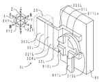
- FIG. 23 is a transparent perspective view of the vicinity of the terminal on the left side of the sensor to be destroyed in the present embodiment.
- the terminal 3L is made of metal and has a plate shape bent in a crank shape as a whole. The terminal 3L is disposed at the left end of the body 20 to be destroyed.
- the terminal 3L includes a fixing portion 30L, an attaching portion 31L, and a connecting portion 32L.
- the attachment portion 31L has a flat plate shape.
- the mounting portion 31L is in contact with the front surface of the mounting object member 81.
- An attachment groove 310L is formed in the attachment portion 31L.
- the mounting groove portion 310L has a U-shape opening leftward.
- the screw 810L is inserted into the mounting groove portion 310L.
- the eyeball portion 811La of the wire 811L is annularly mounted on the body of the screw 810L (see FIG. 19).
- the mounting portion 31L that is, the terminal 3L is fixed to the front surface of the mounting object member 81 by the screw 810L. Further, the terminal 3L and the wiring 811L are connected by the screw 810L.
- the fixed portion 30L includes the buried portion 300L.
- the buried portion 300L has a T-shaped plate pointed to the left.
- the buried portion 300L is buried at the left end of the body 20 to be destroyed.
- the terminal 3L is fixed to the to-be-destructed body 20 by the embedded portion 300L, that is, the fixing portion 30L.
- the buried portion 300L includes an outward surface 300La (shown by a dotted line in FIG. 22) and an inward surface 300Lb (shown by a hatching in FIG. 23).
- the outward facing surface 300La and the inward facing surface 300Lb are disposed at the T-shaped head of the buried portion 300L.
- the outward facing surface 300La is directed longitudinally outward, that is, to the left.
- the inward facing surface 300Lb is directed longitudinally inward, that is, to the right.
- the outward facing surface 300La and the inward facing surface 300Lb face in the left-right direction.
- the connecting portion 32L includes a projecting portion 320L and an extending portion 321L.
- the protrusion 320L has a flat plate shape.
- the protrusion 320L protrudes forward from the right end of the attachment portion 31L.
- the extension part 321L has a T-shaped plate shape pointed to the right.
- the extending portion 321L is continuous with the protruding portion 320L and the embedded portion 300L. When extension part 321L and burial part 300L are put together, it has an H shape as a whole.
- a necked portion 321La is disposed in the T-shaped trunk portion of the extension portion 321L.
- the constricted portion 321La is included in the concept of the "small cross-sectional area" in the present invention.
- the lateral cross-sectional area (shown by hatching in FIG. 23) of the constricted portion 321La is smaller than the lateral cross-sectional area of the other portion of the connecting portion 32L. For this reason, the rigidity of the constricted portion 321La is lower than the rigidity of the other portion of the connecting portion 32L. Therefore, as shown in FIG. 23, assuming that the left-right direction is the X direction, the front-back direction is the Y direction, and the vertical direction is the Z direction, the constricted portion 321La rotates in the XY plane. It is easy to be deformed in the rotation direction ⁇ ZX in the ⁇ YZ, ZX plane.
- the configuration of the terminal 3R is the same as the configuration of the terminal 3L.
- the arrangement of the terminals 3R is symmetrical with the arrangement of the terminals 3L. That is, as shown in FIG. 19, the terminal 3R is fixed to the mounting object member 81 by the screw 810R. Further, the terminal 3R and the wiring 811R are connected by the screw 810R.
- the pair of wires 811L and 811R are electrically connected to a control device (not shown).
- a detection threshold electrical resistance
- a detection threshold electrical resistance
- the terminals 3L and 3R and the body to be destroyed 20 are integrated by insert molding. That is, first, the terminals 3L and 3R are disposed in a state where the fixing portion 30L (embedded portion 300L) partially protrudes in the cavity of the injection molding die, and then the raw material is injected into the cavity to be destroyed By injection-molding the body 20, the terminals 3L and 3R and the body 20 are integrated.
- FIG. 24 the left-right direction sectional view at the time of destruction of the to-be-destructed part of the to-be-destructed sensor of this embodiment is shown.
- the part shown in FIG. 24 is a part corresponding to the inside of the frame XXI in FIG.
- the load F1 is input to the detection target 80 from the front.
- the detection target 80 presses the to-be-destructed portion 201 b of the to-be-destructed body 20 from the front.
- the pressed portion 201b is bent so as to expand rearward between the support portion 200b and the support portion 200c. That is, the to-be-destructed part 201b bends while consuming the stroke S1 secured by the support parts 200b and 200c. For this reason, a tensile force acts on the rear surface of the to-be-destructed part 201b in the left-right direction. Therefore, the load is concentrated at the groove bottom of the notch 202b.
- the body to be destructed 20 is made of an epoxy resin containing carbon beads. For this reason, the to-be-destructed body 20 is fragile. Therefore, due to the load, a crack C1 is generated toward the front at the groove bottom of the notch 202b. When the crack C1 extends to the front surface of the to-be-broken portion 201b, the to-be-broken portion 201b is broken.
- the control device determines that the to-be-broken body 20 has switched from the conductive state to the insulating state. That is, it is determined that the detection target 80 is deformed.
- the sensor 1 to be destroyed 1 detects the deformation of the detection target 80 by being destroyed.
- the control device determines that the to-be-destructed body 20 has switched from the conductive state to the short-circuit state when the electric resistance becomes zero. That is, it is determined that the sensor 1 to be destroyed has broken down.
- FIG. 25 shows a transparent perspective view in the deformed state near the terminal on the left side of the sensor to be destroyed in the present embodiment.
- the part shown in FIG. 25 corresponds to the part shown in FIG.
- the constricted portion 321La can be twisted in the ⁇ YZ direction following the deformation of the to-be-broken body 20. For this reason, distortion is unlikely to occur in the to-be-destructed body 20.
- the constricted portion 321La proactively deforms the to-be-destructed body 20, the strain generated in the to-be-destructed body 20 is absorbed.
- FIG. 26A shows a transparent front view in the reference state near the terminal on the left side of the sensor to be destroyed in the present embodiment.
- FIG. 26 (b) shows a transparent front view in the stretched state near the same terminal.
- FIG. 26C shows a transmission front view in the contracted state near the same terminal.
- the outward facing surface 300La and the inward facing surface 300Lb of the embedded portion 300L both It is in contact with 20. For this reason, the outward surface 300La and the inward surface 300Lb are electrically connected to the body 20 to be destroyed.
- the body 20 to be destroyed and the control device are electrically connected by the outward surface 300La and the inward surface 300Lb.
- the inward facing surface 300Lb and the body 20 are kept in contact with each other. Therefore, the inward facing surface 300Lb and the body 20 are electrically connected. As described above, in the stretched state, the to-be-destructed body 20 and the control device are electrically connected by the inward facing surface 300Lb.
- the outward facing surface 300La and the body 20 are kept in contact with each other. For this reason, the outward facing surface 300La and the body 20 are electrically connected. As described above, in the contracted state, the to-be-broken body 20 and the control device are electrically connected by the outward facing surface 300La.
- the base material of the destructive object 20 is a resin.
- the freedom with respect to the shape of the to-be-destructed body 20 is high. Therefore, it is possible to easily manufacture the strip-like and planar broken parts 201a to 201d as well as the linear shape.
- the to-be-destructed parts 201a to 201d have a planar shape. Therefore, deformation of the detection target 80 can be detected over a wide area. Therefore, it becomes difficult to generate a detection leak.
- the sensor 1 to be destructed according to the present embodiment includes supporting portions 200a to 200e. For this reason, as shown in FIG. 24, it is possible to secure a stroke S1 necessary for the destruction of the parts to be destroyed 201a to 201d between the mounting object member 81 and the parts to be destroyed 201a to 201d.
- the stroke S1 is secured by the supports 200a to 200e. Therefore, regardless of the presence or absence of the deformation of the constricted portion 321La and the degree of the deformation, the portions to be destroyed 201a to 201d can be destroyed by the deformation of the detection object 80. Therefore, detection accuracy is improved.
- the portions to be destroyed 201a to 201d are brittle. For this reason, the stroke S1 necessary for the destruction of the to-be-destructed parts 201a to 201d may be short. Therefore, the thickness in the front-rear direction of the sensor 1 can be reduced. Further, as shown in FIG. 24, since the parts to be broken 201a to 201d are brittle, the parts to be broken 201a to 201d are rapidly broken by the load F1. Therefore, the response delay of the sensor 1 to actual deformation is reduced. Further, since the portions to be broken 201a to 201d are brittle, not only the deformation of the detection object 80 which leads to destruction but also the deformation which does not lead to destruction can be detected.
- the detection sensitivity can be freely adjusted by adjusting the fragility of the parts to be destroyed 201a to 201d. For example, when the portions to be destroyed 201a to 201d are easily broken, deformation can be detected even if the amount of deformation of the detection target 80 is small. That is, the detection sensitivity is increased. When the portions to be destroyed 201a to 201d are not easily broken, deformation can be detected when the amount of deformation of the detection target 80 is large. That is, the detection sensitivity is lowered.
- the integrated unit 20 is disposed. That is, the support portions 200a to 200e and the portions to be broken 201a to 201d are integrally manufactured by injection molding. For this reason, the number of parts is reduced as compared with the case where the support parts 200a to 200e are separate from the parts to be destroyed 201a to 201d. In addition, the number of assembling steps of the sensor 1 to be destructed can be reduced because joining of the support portions 200a to 200e and the portions 201a to 201d is unnecessary. Moreover, the manufacturing cost of the sensor 1 to be destroyed can be reduced.
- the terminals 3L and 3R and the object to be destructed 20 are integrated by insert molding. That is, simultaneously with the formation of the body 20 to be destructed, bonding of the body 20 to be destructed and the terminals 3L and 3R is performed. Therefore, the number of manufacturing steps of the sensor 1 to be destroyed can be reduced. Therefore, the manufacturing cost of the sensor 1 to be destroyed can be reduced.
- the terminals 3L and 3R are also used as a support. For this reason, compared with the case where terminals 3L and 3R are not used as a support part, a number of parts decreases. Moreover, the manufacturing cost of the sensor 1 to be destroyed can be reduced.
- notches 202a to 202d are formed in the to-be-destructed portions 201a to 201d, respectively. Therefore, the to-be-destructed portions 201a to 201d are easily broken. Therefore, even when the amount of deformation of the detection target 80 is small, the deformation can be detected. That is, the detection sensitivity is increased.
- the fracture portions in the to-be-destructed portions 201a to 201d can be guided to the vicinity of the notches 202a to 202d. For this reason, the variation in the detection sensitivity is reduced among the plurality of sensors 1 to be destroyed. In addition, the variation in detection sensitivity is reduced among the plurality of destroyed parts 201a to 201d of the single destroyed sensor 1.
- the to-be-destructed body 20 contains the carbon bead. Therefore, the brittleness and conductivity of the portions to be broken 201a to 201d can be adjusted by the shape, size, filling amount and the like of the carbon beads.
- the sensor 1 to be destroyed of the present embodiment not only the change from the conduction state to the insulation state, but also the change from the conduction state to the short circuit state can be detected. Therefore, the self-diagnostic property of the sensor 1 to be destroyed is high.
- a tensile force acting on the rear surfaces (surfaces in the direction opposite to the direction in which the load F1 is input) of the portions 201a to 201d is used.
- the destroyed parts 201a to 201d are destroyed.
- shear force acting between a portion supported by the support portions 200a to 200e from the rear and a portion not supported by the support portions 200a to 200e from the rear among the portions to be destroyed 201a to 201d As a result, the destroyed parts 201a to 201d are destroyed. Therefore, the to-be-destructed parts 201a to 201d can be destroyed quickly.
- the sensor 1 to be destructed according to the present embodiment, at least a part of the distortion generated in the object 20 to be destructed when attaching the sensor 1 to the mounting object 81
- the portion 321La can be absorbed by deformation. For this reason, there is little possibility that the to-be-destructed body 20 will be destroyed by the stress resulting from the said distortion.
- the amount of thermal deformation (the amount of thermal expansion, the amount of thermal contraction) of the member 2 to be destructed and the terminal 3L are different, or when the amount of thermal deformation of the member 2 to be destructed is different from that of the mounting object member 81 As a result, distortion may occur in the member 2 to be destroyed.
- the sensor 1 to be destroyed 1 of the present embodiment at least a part of the strain can be absorbed by the deformation of the constricted portion 321La of the terminal 3L. For this reason, there is little possibility that the to-be-destructed member 2 will be destroyed by the stress resulting from the said distortion.
- the constricted portion 321La is disposed in the extending portion 321L.
- the rigidity in the front-rear direction (load input direction) of the sensor 1 to be destructed is unlikely to be reduced, as compared with the case where the narrowed portion 321La is disposed in the projecting portion 320L.
- the supporting portions 200a to 200e can be easily held in a floating state from the front surface of the mounting target member 81 as shown in FIG.
- the rigidity of the connecting portion 32L is low by arranging the constricted portion 321La having a smaller cross-sectional area than the other portions of the connecting portion 32L. Low rigidity parts can be introduced. In addition, the torsional rigidity and the bending rigidity of the constricted portion 321La can be reduced.
- the attachment for attaching the destructive sensor 1 to the mounting object member 81, and the portions 201a to 201d to be destructed are electrically connected to the control device.
- the terminals 3L and 3R are commonly used. For this reason, the number of parts of the sensor 1 to be destroyed decreases.
- the buried portion 300L has an outward surface 300La and an inward surface 300Lb. For this reason, even in the case where the to-be-destructed body 20 and the terminal 3L relatively move in the longitudinal direction, at least one of the outward surface 300La and the inward facing surface 300Lb Conduction can be secured.
- the buried portion 300L is buried in the to-be-destructed body 20.
- the meat portion of the body to be destructed 20 is disposed on the left side (longitudinal direction outer side) of the outward facing surface 300La. Therefore, the buried portion 300L is unlikely to drop out of the body 20 to be destroyed.
- the anchor effect of the embedded portion 300L can suppress separation of the terminal 3L and the object 20 to be destructed in the longitudinal direction.
- FIG. 27 is a transparent perspective view of the vicinity of the terminal on the left side of the sensor to be destroyed in the present embodiment.
- part corresponding to FIG. 23 it shows with the same code
- the buried portion 300L of the fixed portion 30L has a C-shape opening to the left.
- the buried portion 300L includes an outward surface 300La and an inward surface 300Lb (shown by hatching in FIG. 27).
- the outward facing surface 300La and the inward facing surface 300Lb are disposed at the C-shaped bottom of the embedded portion 300L.
- the outward facing surface 300La is directed longitudinally outward, that is, to the left.
- the inward facing surface 300Lb is directed longitudinally inward, that is, to the right.
- the outward facing surface 300La and the inward facing surface 300Lb face in the left-right direction.
- the extending portion 321L of the connecting portion 32L has a C-shape opening to the right. That is, the hollow portion 321Lb is disposed in the extension portion 321L.
- the hollow portion 321Lb is included in the concept of the "small cross-sectional area portion" in the present invention.
- a through hole 321Lc penetrating the connecting portion is bored in the up and down direction inside of the hollow portion 321Lb.
- the lateral cross-sectional area (indicated by hatching in FIG. 27) of the hollow portion 321Lb is smaller than the lateral cross-sectional area of the other portion of the connecting portion 32L. For this reason, the rigidity of the hollowed portion 321Lb is lower than the rigidity of the other portion of the connecting portion 32L. Therefore, the hollow portion 321Lb is easily deformed in the direction ⁇ XY rotating in the XY plane, the direction ⁇ YZ rotating in the YZ plane, and the direction ⁇ ZX rotating in the ZX plane.
- the damage sensor of the present embodiment and the damage sensor of the seventh embodiment have the same effects as those of the parts having the same configuration. Moreover, according to the sensor to be destroyed of the present embodiment, the hollow portion 321Lb is disposed in the extension portion 321L. For this reason, the rigidity in the front-rear direction (load input direction) of the sensor 1 to be destructed is less likely to decrease compared to the case where the hollow portion 321Lb is disposed in the protrusion 320L. In addition, since the rigidity of the protrusion 320L does not easily decrease, the support can be easily held in a floating state from the front surface of the mounting target member 81.
- the low rigidity portion with low rigidity is introduced to the connecting portion 32L by arranging the hollow portion 321Lb having a smaller cross-sectional area than the other portions of the connecting portion 32L. be able to.
- the torsional rigidity and bending rigidity of the hollow portion 321Lb can be reduced.
- FIG. 28 shows a left-right direction cross-sectional view in the vicinity of the left terminal of the sensor to be destroyed in the present embodiment. Note that portions corresponding to those in FIG. 22 are denoted by the same reference numerals.
- the attaching portion 31L, the projecting portion 320L, and the extending portion 321L are connected in an S shape.
- the low rigidity portion 322La is disposed between the mounting portion 31L and the protruding portion 320L in a chamfered shape.
- the low rigidity portion 322Lb is disposed in a round bevel shape between the projecting portion 320L and the extending portion 321L.
- the damage sensor of the present embodiment and the damage sensor of the seventh embodiment have the same effects as those of the parts having the same configuration.
- the low rigidity portions 322La and 322Lb of the sensor to be destroyed in the present embodiment have low rigidity in the left-right direction. For this reason, when the low rigidity portions 322La and 322Lb deform at least a part of the distortion in the left-right direction that occurs in the to-be-destructed body 20 when attaching the to-be-broken sensor 1 to the mounting object member 81 Can be absorbed. For this reason, there is little possibility that the to-be-destructed body 20 will be destroyed by the stress resulting from the said distortion.
- FIG. 29 shows a cross-sectional view in the left-right direction near the terminal on the left side of the sensor to be destroyed in the present embodiment. Note that portions corresponding to those in FIG. 22 are denoted by the same reference numerals.
- a zigzag bending portion 323L is disposed in the extending portion 321L.
- the damage sensor of the present embodiment and the damage sensor of the seventh embodiment have the same effects as those of the parts having the same configuration.
- the bending portion 323L of the sensor to be destroyed in the present embodiment has low rigidity in the left-right direction. For this reason, at least a part of the distortion in the left-right direction that occurs in the to-be-destructed body 20 when attaching the to-be-broken sensor to the mounting target member 81 is absorbed by the bending portion 323L being deformed can do. Therefore, there is little possibility that the to-be-destructed body 20 will be destroyed by the stress resulting from the said distortion.
- the rear surface of the support portion 200 a may be in contact with the front surface of the mounting object member 81 in the mounting state.
- the fixing portion 30L may be bonded to the left end surface of the body 20 to be destroyed. That is, the fixed portion 30L may not have the buried portion.
- FIG. 30 shows a left-right direction cross-sectional view in the vicinity of the left terminal of the sensor to be destroyed in the present embodiment. Parts corresponding to those in FIG. 29 are denoted by the same reference numerals.
- the cross-sectional area s1 of the fixing portion 30L in the direction orthogonal to the fixing portion extension direction and the cross-sectional area s2 in the direction orthogonal to the bending portion extending direction of the bending portion 323L substantially coincide with each other.
- the damage sensor according to the present embodiment and the damage sensor according to the tenth embodiment have the same function and effect as for the parts having the same configuration.
- the bending portion 323L of the sensor to be destroyed in the present embodiment has low rigidity in the left-right direction.
- the twelfth embodiment The difference between the sensor to be destroyed in the present embodiment and the sensor to be destroyed in the seventh embodiment is only the configuration of the terminal. Here, only the differences will be described.
- FIG. 31 the permeation
- the constricted portion 321La of the left terminal 3L is disposed along the lower edge of the terminal 3L.
- the constricted portion 321Ra of the right terminal 3R is disposed along the upper edge of the terminal 3R. That is, the constricted portion 321La and the constricted portion 321Ra are arranged to be shifted in the vertical direction.
- the damage sensor 1 of the present embodiment and the damage sensor of the seventh embodiment have the same effects as those of the parts having the same configuration. Moreover, according to the sensor 1 to be broken 1 of the present embodiment, the constricted portion 321La and the constricted portion 321Ra are arranged to be vertically shifted. For this reason, at least a part of the distortion in the left-right direction that occurs in the to-be-destructed body 20 when attaching the to-be-broken sensor 1 to the attachment target member 81 is absorbed by deformation of at least one of the narrow portion 321La and the narrow portion 321Ra. can do. Therefore, there is little possibility that the to-be-destructed body 20 will be destroyed by the stress resulting from the said distortion.
- FIG. 32 is a transparent perspective view of the vicinity of the terminal on the left side of the sensor to be destroyed in the present embodiment.
- part corresponding to FIG. 23 it shows with the same code
- the cross-sectional area (shown by hatching in FIG. 32) of the connecting portion 32L is smaller than the cross-sectional area of the fixing portion 30L and the mounting portion 31L. Therefore, as shown in FIG. 32, the connecting portion 32L is easily deformed in the direction ⁇ XY rotating in the XY plane, the direction ⁇ YZ rotating in the YZ plane, and the direction ⁇ ZX rotating in the ZX plane.
- the damage sensor of the present embodiment and the damage sensor of the seventh embodiment have the same effects as those of the parts having the same configuration. Further, as in the sensor to be destructed according to the present embodiment, the entire connecting portion 32L may be a low rigidity portion.
- FIG. 33 is a transparent perspective view of the vicinity of the terminal on the left side of the sensor to be destroyed in the present embodiment.
- part corresponding to FIG. 23 it shows with the same code
- the transverse direction cross-sectional area (indicated by hatching in FIG. 33) of the connecting portion 32L is smaller than the transverse direction cross-sectional area of the fixing portion 30L and the attachment portion 31L. Therefore, as shown in FIG. 33, the connecting portion 32L is easily deformed in the rotating direction ⁇ XY in the XY plane, the rotating direction ⁇ YZ in the YZ plane, and the rotating direction ⁇ ZX in the ZX plane.
- the damage sensor of the present embodiment and the damage sensor of the seventh embodiment have the same effects as those of the parts having the same configuration. Further, as in the sensor to be destructed according to the present embodiment, the entire connecting portion 32L may be a low rigidity portion.
- FIG. 34 is a transparent perspective view of the vicinity of the terminal on the left side of the sensor to be destroyed in the present embodiment.
- part corresponding to FIG. 23 it shows with the same code
- the front-rear direction plate thickness of the small cross-sectional area 324L is smaller than the plate thickness of the other portion of the connecting portion 32L.
- the crosswise cross-sectional area (it shows by hatching in FIG. 34) of the small cross-sectional area part 324L is smaller than the crosswise cross-sectional area of the other part of the connection part 32L. Therefore, as shown in FIG. 34, the small cross-sectional area 324L is easily deformed in the rotating direction ⁇ XY in the XY plane, the rotating direction ⁇ YZ in the YZ plane, and the rotating direction ⁇ ZX in the ZX plane.
- the damage sensor of the present embodiment and the damage sensor of the seventh embodiment have the same effects as those of the parts having the same configuration. Further, as in the sensor to be destructed according to the present embodiment, the small cross-sectional area portion 324L may be disposed in the connecting portion 32L by reducing the plate thickness (thickness).
- the front-rear direction corresponds to the "load transfer direction” of the present invention
- the left-right direction corresponds to the "orthogonal direction” of the present invention.
- the vertical direction and the horizontal direction may correspond to the "load transfer direction” of the present invention.
- the vertical direction and the front-rear direction may correspond to the “orthogonal direction” of the present invention.
- the materials of the detection target 80 and the mounting target member 81 are not particularly limited. For example, resin, metal, etc. which have insulation may be sufficient. In the case where the detection target 80 and the mounting target member 81 have conductivity, an insulating layer (the cover member of the sixth embodiment) having insulation between these members and the sensor 1 to be destructed (the object 20 to be destructed) 22) is better. This can suppress conduction between the to-be-destructed body, the to-be-destructed portion, the terminal, and the detection object 80 and the attachment target member 81.
- the material of the insulating layer and the cover member 22 is not particularly limited. Polypropylene, polystyrene, polycarbonate, polyamide, polyacetal, acrylic resin, silicone resin, phenol resin, epoxy resin, unsaturated polyester resin and the like can be used.
- the shape, arrangement, and number of the notches 202a to 202d are not particularly limited.
- 35 (a) to 35 (c) show cross-sectional views around the notch of the sensor to be destroyed. In addition, about the site
- a notch 207a having a planar bottom surface may be disposed on one surface of the portion to be destroyed 207.
- a notch 207b having a U-shaped cross section may be disposed on one surface of the portion to be destroyed 207.
- a pair of notches 207c having a V-shaped cross section may be arranged on one surface of the portion to be broken 207. Further, a notch 207 d having a V-shaped cross section may be disposed on the other surface of the portion to be destroyed 207. Further, as viewed in the thickness direction, the notches 207 d and the notches 207 c may be offset from each other.
- the fragile portion and the load concentration portion may be set in the to-be-destructed portion by a method other than the notch formation.
- a through hole may be formed in the portion to be destroyed.
- the thickness of the portion to be destroyed in the load transfer direction may be partially reduced.
- FIG. 36 shows a cross-sectional view in the left-right direction of another damage sensor (part 1).
- the destructive sensor 1 may be attached to the detection target 80.
- the detection target 80 doubles as a mounting target member (mounting member).
- an insulating resin sheet 800 having insulation may be interposed between the detection target 80 and the sensor 1 to be destroyed.
- the insulating sheet 800 may be interposed between the detection target 80 and the screws 810L and 810R.
- the pressing member 82 that induces the destruction of the sensor 1 may be disposed to face the object to be detected 80.
- the left-right direction sectional view of the other to-be-broken sensor (the 2) is shown in FIG.
- the back surfaces of the support portions 200a to 200e may be separated from the front surface of the mounting object member 81 before the load is input. That is, the entire body to be destroyed 20 may be attached to the mounting object member 81 in a state of floating in the front (load input direction) with respect to the front surface of the mounting object member 81 by the terminals 21L and 21R.
- the rear surface of the detection target 80 and the front surface of the to-be-destructed body 20 may be separated. In this way, it is possible to suppress transmission of sounds, vibrations, and the like through the contact interface in a state before the load is input.
- the presence or absence of deformation of the detection target 80 is detected by the destruction sensor 1.
- the presence or absence of the displacement of the detection target 80 may be detected.
- a change in relative positional relationship between the detection target 80 and the mounting target member 81 may be detected.
- the detection object 80 is detected via the deformation of the detection object 80. The presence or absence of the load F1 input to may be detected.
- the crush sensor 1 can detect the detection target 80 and the mounting target member 81. It is possible to detect changes in relative positional relationship between the two.
- circuit 90 shown in FIG. 5 is disposed in the control device in the above embodiment, it may be disposed in the sensor 1 to be destroyed.
- the power supply 900 may be separately disposed in the control device, and the first resistor 901 and the second resistor 902 may be separately disposed in the sensor 1 to be destroyed.
- the shape, size, and the like of the to-be-destructed body 20 are not particularly limited.
- the object to be destructed 20 has a zigzag plate shape, but may have a flat plate shape, a rectangular wave plate shape, a sine wave plate shape or the like.
- the shape, size, etc. of the portion to be destroyed are not particularly limited.
- the fragility of the portion to be destroyed can be adjusted by appropriately changing the shape of the notch, the location, the number, the distance between the adjacent support portions, the shape of the portion to be broken, and the like.
- the two cover member side protrusions 221 b and 221 c are arranged corresponding to the two destroyed parts 201 b and 201 c.
- the arrangement number of the cover member side protrusions 221 b and 221 c is not particularly limited.
- a total of four cover member side protrusions 221b and 221c may be arranged to correspond to all the destroyed parts 201a to 201d.
- the single cover member side protrusions 221b and 221c may be disposed to correspond to the single destroyed parts 201a to 201d.
- the arrangement number of the protrusions 223b and 223c is not particularly limited.
- thermoplastic resin for the base material of the portion to be destroyed for example, PE, polypropylene (PP), polyvinyl chloride (PVC), polystyrene (PS), polyvinyl acetate (PVAc), polytetrafluoroethylene (PTFE), acrylonitrile -Butadiene-Styrene (ABS) resin, acrylic resin, polyamide (PA), polyacetal (POM), polycarbonate (PC), polyphenylene oxide (PPO), PET, polybutylene terephthalate (PBT), amorphous fluorine resin, amorphous Quality polyester resin and phenoxy resin.
- PE polypropylene
- PVC polyvinyl chloride
- PS polystyrene
- PVAc polyvinyl acetate
- PTFE polytetrafluoroethylene
- ABS acrylonitrile -Butadiene-Styrene
- acrylic resin acrylic resin
- PA polyamide
- POM polyacetal
- PC polycarbonate
- thermosetting resin for the base material of the destructible portion
- epoxy resin alkyd resin, phenol resin, urea resin, melamine resin, unsaturated polyester resin, polyurethane, polyimide resin and the like can be mentioned.
- the conductive filler is not particularly limited as long as it has conductivity.
- fine particles of carbon materials, metals and the like can be mentioned. Among these, one can be used alone, or two or more can be used in combination.
- the conductive filler has a true sphere or a shape (substantially spherical) close to a true sphere. It is good to adopt particles.
- the filling ratio of the conductive filler is preferably 30% by volume or more when the volume of the body to be destructed 20 and the portions to be destructed 201a to 201d, 205a to 205u, 206, and 207 is 100% by volume. If it is less than 30% by volume, it is difficult for the conductive path of the conductive filler to be formed, and the desired conductivity is unlikely to be developed. It is more preferable that it is 35 volume% or more.
- the filling rate of the conductive filler is 65 volume% or less when the volume of the body to be destructed 20 and the parts to be destructed 201 a to 201 d, 205 a to 205 u, 206, and 207 is 100 volume%.
- it exceeds 65 volume% mixing to a base material will become difficult and molding processability will fall.
- the conductive filler be present in the form of primary particles without aggregation. Therefore, when selecting the conductive filler, it is preferable to consider the average particle diameter, the compatibility with the base material, and the like.
- the average particle diameter of the conductive filler present in the state of primary particles is desirably 0.05 ⁇ m or more and 100 ⁇ m or less. If it is less than 0.05 ⁇ m, it tends to agglomerate to form secondary particles. It is suitable that it is 0.5 micrometer or more, and also 1 micrometer or more.
- the average particle diameter exceeds 100 ⁇ m, it is difficult to reduce the thickness of the body to be destructed 20 and the portions to be destructed 201a to 201d, 205a to 205u, 206, and 207. It is suitable that it is 60 micrometers or less, and also 30 micrometers or less.
- the conductive filler may be appropriately selected from silver, gold, copper, nickel, rhodium, palladium, chromium, titanium, platinum, iron, aluminum, alloys thereof, carbon and the like.
- carbon beads are preferred. Carbon beads have good conductivity and are relatively inexpensive.
- they since they exhibit a substantially spherical shape, they can be blended at a high filling rate.
- an insulating filler may be added to the base material.
- the insulating filler can be selected from metal oxides and ceramics.
- glass fibers may be added as an insulating filler in order to control the cracking load (the load at which the to-be-broken parts 201a to 201d, 205a to 205u, 206, and 207 are broken).
- the to-be-destructed body 20 and the to-be-destructed portions 201a to 201d, 205a to 205u, 206, and 207 can be manufactured, for example, as follows.
- a thermoplastic resin is selected as the base material
- a conductive filler and, if necessary, an additive are added to and mixed with the heat-melted thermoplastic resin, and then press molding, injection molding and the like are performed.
- a thermosetting resin is selected as the base material, a curing agent and, if necessary, an additive are added to the resin before curing and mixed, and then curing is performed by press molding or the like.
- the constricted portions 321La and 321Ra, the hollow portions 321Lb, the low rigidity portions 322La and 322Lb, the bent portions 323L, and the small cross-sectional area portions 324L (hereinafter collectively referred to as "low rigidity portions") It should just be arrange
- the breakdown of the to-be-broken portions 201a to 201d is detected from the change of the electric resistance of the to-be-broken body 20, but the breakdown of the to-be-broken portions 201a to 201d is detected from other electric quantities such as voltage and current. It is also good.
Landscapes
- Physics & Mathematics (AREA)
- General Physics & Mathematics (AREA)
- Measurement Of Length, Angles, Or The Like Using Electric Or Magnetic Means (AREA)
- Burglar Alarm Systems (AREA)
Abstract
検出漏れが発生しにくく、破壊に至らない検出対象物の変形を検出可能で、検出感度を容易に調整することが可能な被破壊センサを提供することを課題とする。被破壊センサ1は、取付対象部材81に対向して配置され、母材が樹脂であって脆性および導電性を併有する被破壊部201a~201dと、被破壊部201a~201dと取付対象部材81との間に介装され、取付対象部材81との間に被破壊部201a~201dが破壊される際のストロークS1を確保する複数の支持部200a~200eと、を有する被破壊部材2を備える。被破壊センサ1は、被破壊部201a~201dの破壊前後において電気抵抗が変化することを基に、検出対象物80の変形を検出する。
Description
本発明は、破壊されることにより検出対象物の変形を検出する被破壊センサに関する。
特許文献1には、窓ガラスの破壊検出方法が開示されている。窓ガラスの室内側の表面には、錠を中心に、導電性ワイヤが一筆書状に貼り付けられている。窓ガラスが破壊されると、導電性ワイヤが断線する。同文献記載の破壊検出方法によると、当該断線を基に、窓ガラスの破壊を検出している。
しかしながら、導電性ワイヤは線状を呈している。このため、検出漏れが発生しやすい。すなわち、窓ガラスの、導電性ワイヤが配置されていない部分が破壊される場合、導電性ワイヤは断線しない。この場合、窓ガラスの破壊を検出することができない。また、同文献記載の破壊検出方法によると、窓ガラスに直に導電性ワイヤが貼り付けられている。このため、窓ガラスから独立して、選択的に導電性ワイヤだけを破壊することは困難である。したがって、破壊に至らない窓ガラスの変形を検出することが困難である。また、窓ガラス自体の壊れやすさに、導電性ワイヤの断線しやすさ、すなわち検出感度が支配されてしまう。このため、検出感度を調整することが困難である。
本発明の被破壊センサは、上記課題に鑑みて完成されたものである。本発明は、検出漏れが発生しにくく、破壊に至らない検出対象物の変形を検出可能で、検出感度を容易に調整することが可能な被破壊センサを提供することを目的とする。
(1)上記課題を解決するため、本発明の被破壊センサは、脆性を有する被破壊部を有する被破壊部材を備え、該被破壊部の破壊を基に、検出対象物の変形を検出することを特徴とする。
ここで、検出対象物の「変形」には、検出対象物の変位(移動)も含まれる。被破壊部の有する「脆性」とは、一般的に脆性材料と言われている、ガラス、セラミックスなどの有する脆性と、同等の脆性をいう。
被破壊部は、脆性を有している。このため、被破壊部の破壊に必要なストロークが短くて済む。したがって、被破壊センサの荷重伝達方向の肉厚を薄くすることができる。また、被破壊部が脆性を有しているため、検出対象物の変形により加えられる荷重により、被破壊部は迅速に破壊される。したがって、実際の変形に対する被破壊センサの応答遅れが小さくなる。また、被破壊部が脆性を有しているため、検出対象物の、破壊に至る変形は勿論、破壊に至らない変形も検出することができる。
また、被破壊部の壊れやすさを調整することで、検出感度を自在に調整することができる。例えば、被破壊部を壊れやすくすると、検出対象物の変形量が小さい場合であっても、変形を検出することができる。すなわち、検出感度が高くなる。被破壊部を壊れにくくすると、検出対象物の変形量が大きい場合に、変形を検出することができる。すなわち、検出感度が低くなる。
(2)好ましくは、上記(1)の構成において、前記被破壊部は、取付部材に対向して配置され、母材が樹脂であって脆性および導電性を併有し、前記被破壊部材は、該被破壊部と該取付部材との間に介装され、該取付部材との間に該被破壊部が破壊される際のストロークを確保する複数の支持部を有し、該被破壊部の破壊前後において電気抵抗が変化することを基に、前記検出対象物の変形を検出する構成とする方がよい。
本構成によると、被破壊部の母材が樹脂である。このため、被破壊部の形状に対する自由度が高い。したがって、線状は勿論、帯状や面状の被破壊部を簡単に作製することができる。検出対象物に対して帯状や面状の被破壊部を配置すると、広い面積に亘って検出対象物の変形を検出することができる。このため、検出漏れが発生しにくくなる。
また、本構成の被破壊センサは、複数の支持部を備えている。外部から荷重が入力される際、複数の支持部は、取付部材に対して、被破壊部を、浮いた状態で支持している。このため、取付部材と被破壊部との間に、被破壊部の破壊に必要なストロークを確保することができる。
(2-1)好ましくは、上記(2)の構成において、前記被破壊部は、取付部材と、該取付部材に対向する押圧部材と、の間に介装される構成とする方がよい。本構成によると、取付部材と押圧部材との間の間隔が小さくなることを利用して、被破壊部を破壊することができる。
(3)好ましくは、上記(2)の構成において、前記被破壊部材は、複数の前記支持部のうち少なくとも一つと、前記被破壊部と、を有する一体物の被破壊体を備える構成とする方がよい。
本構成によると、全ての支持部が被破壊部と別体である場合と比較して、部品点数が少なくなる。また、全ての支持部と被破壊部との接合が不要な分、被破壊センサの組付工数が少なくなる。また、被破壊センサの製造コストを削減することができる。
(4)好ましくは、上記(2)または(3)の構成において、複数の前記支持部のうち少なくとも一つは、前記被破壊部の前記電気抵抗に関する電気量を出力する端子である構成とする方がよい。
本構成によると、端子を支持部として用いることができる。このため、端子を支持部として用いない場合と比較して、部品点数が少なくなる。また、被破壊センサの製造コストを削減することができる。
(4-1)好ましくは、上記(4)の構成において、前記端子は前記被破壊部よりも脆性が低く、該被破壊部は該端子を介して前記取付部材に取り付けられる構成とする方がよい。
本構成によると、被破壊部は、端子を介して取付部材に取り付けられる。端子(例えば金属製)は被破壊部よりも脆性が低い。すなわち、変形しても壊れにくい。このため、被破壊センサを取付部材に取り付ける際、端子が変形することにより、被破壊部に歪みが残留するのを、抑制することができる。したがって、被破壊部が残留歪みにより破壊されやすくなるのを、抑制することができる。
(4-2)好ましくは、上記(4)の構成において、前記端子以外の前記支持部は、外部から荷重が入力される前は前記取付部材から浮いており、該荷重が入力されることにより該取付部材に当接する構成とする方がよい。本構成によると、取付部材からの振動が、支持部を介して、被破壊部に伝達されにくくなる。
(5)好ましくは、上記(2)ないし(4)のいずれかの構成において、前記被破壊部に荷重が伝達される方向を荷重伝達方向、該荷重伝達方向に直交する方向を直交方向として、前記被破壊部材は、波長方向が該直交方向、振幅方向が該荷重伝達方向である波板状を呈し、複数の前記支持部のうち少なくとも一つは、該被破壊部材の振幅の頂部に配置される構成とする方がよい。本構成によると、被破壊部材の形状(波板状)を利用して、支持部、被破壊部が配置されている。
(6)好ましくは、上記(2)ないし(5)のいずれかの構成において、前記被破壊部は、自身の破壊を誘起するノッチを有する構成とする方がよい。本構成によると、被破壊部が破壊されやすくなる。このため、検出対象物の変形量が小さい場合であっても、変形を検出することができる。すなわち、検出感度が高くなる。また、被破壊部における破壊箇所を、ノッチ付近に誘導することができる。このため、複数の被破壊センサ間において、検出感度のばらつきが小さくなる。また、被破壊部が複数配置されている場合は、複数の被破壊部間において、検出感度のばらつきが小さくなる。
(7)好ましくは、上記(2)ないし(6)のいずれかの構成において、前記被破壊部は、前記母材中に充填される導電性フィラーを有する構成とする方がよい。本構成によると、導電性フィラーの形状、大きさ、充填量などにより、被破壊部の脆性、導電性を調整することができる。
(8)好ましくは、上記(2)ないし(7)のいずれかの構成において、前記被破壊部の破断伸びは、5%以下である構成とする方がよい。ここで、破断伸びを5%以下としたのは、5%超過の場合、所望の脆性が得られにくくなるからである。より高い脆性を得るためには、被破壊部の破断伸びを1%以下とする方がよい。
(9)好ましくは、上記(2)ないし(8)のいずれかの構成において、前記被破壊部材は、前記被破壊部の表側に配置されるカバー部材を備え、該カバー部材は、該被破壊部に取り付けられ該被破壊部の面方向に所定間隔だけ離間して配置される一対のカバー部材側取付部と、一対の該カバー部材側取付部の中間に配置され該被破壊部の表面との間に隙間を区画し荷重が入力されるカバー部材側突出部と、一対の該カバー部材側取付部と該カバー部材側突出部とを連結する一対のカバー部材側連結部と、を有する構成とする方がよい。
本構成によると、一対のカバー部材側連結部を介して、カバー部材側突出部から一対のカバー部材側取付部に、荷重が伝達される。このため、被破壊部には、面方向外側に広げられるように、荷重が作用する。したがって、一旦分離した被破壊部の破片同士が、再度繋がるおそれが小さい。言い換えると、一旦導通状態から絶縁状態に切り替わった被破壊センサが、再度絶縁状態から導通状態に切り替わるおそれが小さい。このため、検出対象物の変形に対する検出漏れの発生を抑制することができる。
(10)好ましくは、上記(9)の構成において、一対の前記支持部は、前記被破壊部の前記面方向両側に配置され、一対の前記カバー部材側取付部は、一対の該支持部の該面方向内側に配置され、一対の前記カバー部材側連結部を介して、前記カバー部材側突出部から一対の該カバー部材側取付部に、荷重が伝達されることにより、一対の該カバー部材側取付部は、一対の該支持部を該面方向外側に押圧する構成とする方がよい。
本構成によると、一対のカバー部材側連結部を介して、カバー部材側突出部から一対のカバー部材側取付部に、荷重が伝達される。一対のカバー部材側取付部は、一対の支持部を、面方向外側に押圧する。このため、被破壊部には、一対の支持部を介して、面方向外側に広げられるように、荷重が作用する。したがって、一旦分離した被破壊部の破片同士が、再度繋がるおそれが小さい。
(11)好ましくは、上記(9)または(10)の構成において、前記カバー部材は、前記カバー部材側突出部の裏面から裏側に突出する突起を有する構成とする方がよい。本構成によると、突起を介して、カバー部材側突出部から被破壊部に、表裏方向に荷重が伝達される。並びに、一対のカバー部材側連結部を介して、カバー部材側突出部から被破壊部に、面方向に荷重が伝達される。すなわち、入力される荷重を、表裏方向分力と面方向分力とに分けて、被破壊部に伝達することができる。このため、被破壊部を、簡単に、破壊かつ分離することができる。
(12)好ましくは、上記(9)ないし(11)のいずれかの構成において、前記カバー部材は、絶縁性を有する構成とする方がよい。本構成によると、外部に対する被破壊部の絶縁性を確保することができる。特に、本構成と上記(11)の構成とを組み合わせる場合、一旦分離した被破壊部の破片間に突起が介入することにより、当該破片同士が再結合するのを抑制することができる。
(13)好ましくは、上記(1)の構成において、前記被破壊部材に固定される固定部と、取付対象部材に取り付けられる取付部と、該固定部と該取付部とを連結する連結部と、を有する複数の取付具を備え、複数の該取付具のうち、少なくとも一つの該取付具の該連結部は、前記被破壊部よりも剛性が低い低剛性部を有する構成とする方がよい。ここで、本構成における「取付対象部材」は、上記(2)の構成の「取付部材」に対応する。
本発明の被破壊センサは、壊れやすい(脆性を有する)被破壊部を有している。この被破壊センサによると、被破壊部の壊れやすさを調整することにより、検出感度を調整することができる。また、破壊に至らないような検出対象物の変形であっても、当該変形により被破壊部だけが選択的に壊れるように検出感度を調整することで、当該変形を検出することができる。被破壊部が破壊されると、被破壊センサは使用できなくなる。すなわち、被破壊センサは一度しか使えない。このため、検出対象物の変形以外の要因により被破壊部が破壊されることは好ましくない。
しかしながら、被破壊センサの寸法誤差(設計形状と実際形状との違い)、被破壊センサを取り付ける取付対象部材の寸法誤差などにより、被破壊部に歪みが発生した状態で、被破壊センサが取付対象部材に取り付けられている場合がある。この場合、当該歪みに起因する応力により、被破壊部が破壊されるおそれがある。
この点、本構成によると、被破壊センサを取付対象部材に取り付ける際に被破壊部に生じる歪みの少なくとも一部を、取付具の低剛性部が変形することにより、吸収することができる。このため、当該歪みに起因する応力により、被破壊部が破壊されるおそれが小さい。
また、被破壊部材と取付具との熱変形量(熱膨張量、熱収縮量)が異なる場合、あるいは被破壊部材と取付対象部材との熱変形量が異なる場合、温度変化に起因して、被破壊部材に歪みが生じるおそれがある。この点、本構成によると、当該歪みの少なくとも一部を、取付具の低剛性部が変形することにより、吸収することができる。このため、当該歪みに起因する応力により、被破壊部が破壊されるおそれが小さい。
(13-1)好ましくは、上記(13)の構成において、前記被破壊部は、自身の破壊を誘起するノッチを有する構成とする方がよい。本構成によると、被破壊部が破壊されやすくなる。このため、検出対象物の変形量が小さい場合であっても、変形を検出することができる。すなわち、検出感度が高くなる。また、被破壊部における破壊箇所を、ノッチ付近に誘導することができる。このため、複数の被破壊センサ間において、検出感度のばらつきが小さくなる。また、単一の被破壊センサに被破壊部が複数配置されている場合は、複数の被破壊部間において、検出感度のばらつきが小さくなる。
(13-2)好ましくは、上記(13)の構成において、前記被破壊部の破断伸びは、5%以下である構成とする方がよい。ここで、破断伸びを5%以下としたのは、5%超過の場合、所望の脆性が得られにくくなるからである。より高い脆性を得るためには、被破壊部の破断伸びを1%以下とする方がよい。
(14)好ましくは、上記(13)の構成において、前記被破壊部材は、前記被破壊部から前記取付対象部材側に突設され、該取付対象部材との間に該被破壊部が破壊される際のストロークを確保する支持部を有する構成とする方がよい。
検出対象物が変形する際、低剛性部が変形すると、その分被破壊部が壊れにくくなるおそれがある。このため、検出精度が低下する。この点、本構成によると、支持部により被破壊部が破壊される際のストロークが確保されている。このため、低剛性部の変形の有無、変形の程度によらず、検出対象物の変形により被破壊部を破壊することができる。したがって、検出精度が向上する。
(14-1)好ましくは、上記(14)の構成において、前記被破壊部材は、前記被破壊部と前記支持部とを有する一体物の被破壊体を備える構成とする方がよい。本構成によると、被破壊部材の部品点数が少なくなる。
(15)好ましくは、上記(13)または(14)の構成において、前記連結部は、前記取付部から荷重入力側に突出する突出部と、該突出部に対して交差する方向に延在する延在部と、を有し、該延在部は、前記低剛性部を有する構成とする方がよい。
突出部に低剛性部を配置すると(ただし、この場合も上記(13)の構成に含まれる。)、被破壊センサの荷重入力方向の剛性が低くなってしまう。この点、本構成によると、突出部ではなく延在部に低剛性部が配置されている。このため、被破壊センサの荷重入力方向の剛性が低下しにくい。
(16)好ましくは、上記(15)の構成において、前記低剛性部は、前記延在部の突出部側端部と固定部側端部とを結ぶ直線に対して、屈曲している屈曲部である構成とする方がよい。
本構成によると、延在部の突出部側端部と固定部側端部とを結ぶ直線に対する屈曲により、剛性を調整することができる。すなわち、延在部に屈曲部を配置することにより、屈曲部の剛性を下げることができる。
(17)好ましくは、上記(13)ないし(16)のいずれかの構成において、前記低剛性部は、前記連結部の延在方向に対して直交する方向の断面積が、該連結部の他の部分よりも、小さい小断面積部である構成とする方がよい。本構成によると、断面積により剛性を調整することができる。すなわち、連結部に小断面積部を配置することにより、小断面積部の剛性を下げることができる。
(17-1)好ましくは、上記(17)の構成において、前記小断面積部は、前記連結部の他の部分に対して、該連結部の延在方向に対して直交する方向に縮幅する括れ部である構成とする方がよい。本構成によると、括れ部の捻れ剛性、曲げ剛性を低下させることができる。
(17-2)好ましくは、上記(17)の構成において、前記小断面積部は、前記連結部を貫通する貫通孔を有する中抜き部である構成とする方がよい。本構成によると、中抜き部の捻れ剛性、曲げ剛性を低下させることができる。
(18)好ましくは、上記(13)ないし(17)のいずれかの構成において、前記被破壊部は導電性を有し、複数の前記取付具のうち、一対の該取付具は、該被破壊部の破壊に関する電気量を出力する一対の端子である構成とする方がよい。本構成によると、取付具と端子とが共用化されている。このため、被破壊センサの部品点数が少なくなる。
(18-1)好ましくは、上記(18)の構成において、前記被破壊部は、樹脂製の母材と、該母材中に充填される導電性フィラーと、を有する構成とする方がよい。本構成によると、導電性フィラーにより、被破壊部の導電性を確保することができる。また、導電性フィラーの母材に対する充填率により、導電性を調整することができる。
(19)好ましくは、上記(18)の構成において、一対の前記端子は、前記被破壊部材の長手方向両端部に配置され、該端子の前記固定部は、該被破壊部材に埋設され、該長手方向に対して交差する方向に延在し該長手方向外向きの外向面と、該長手方向に対して交差する方向に延在し該長手方向内向きの内向面と、を有する埋設部を有する構成とする方がよい。
被破壊センサの環境温度が変化すると、当該温度変化に起因して、被破壊部材と端子とが長手方向に相対的に移動するおそれがある。この場合、被破壊部材と端子との間の導通を確保しにくくなる。
この点、本構成によると、固定部の埋設部が外向面と内向面とを有している。このため、被破壊部材と取付具とが長手方向に相対的に移動する場合であっても、外向面および内向面のうち、少なくとも一方により、被破壊部材と端子との間の導通を確保することができる。
また、埋設部は、被破壊部材に埋設されている。このため、外向面の長手方向外側には、被破壊部材の肉部が配置されている。したがって、埋設部が被破壊部材から長手方向に脱落しにくい。このように、本構成によると、埋設部のアンカー効果により、端子と被破壊部材とが長手方向に分離するのを抑制することができる。
(20)好ましくは、上記(18)または(19)の構成において、一対の前記端子は、前記被破壊部材の長手方向両端部に配置され、一対の該端子は、該被破壊部材に長手方向両側から圧縮荷重を加えた状態で、前記取付対象部材に取り付けられる構成とする方がよい。
被破壊部材と端子との熱変形量(熱膨張量、熱収縮量)が異なる場合、あるいは被破壊部材と取付対象部材との熱変形量が異なる場合、温度変化に起因して、端子に対して、被破壊部材が長手方向内側に移動するおそれがある。この場合、被破壊部材と端子との間の導通を確保しにくくなる。
この点、本構成によると、予め、一対の端子は、被破壊部材に長手方向両側から圧縮荷重を加えた状態で、取付対象部材に取り付けられている。このため、温度変化に起因して、端子に対して、被破壊部材が長手方向内側に移動する場合であっても、当該移動に端子が追随することができる。したがって、被破壊部材と端子との間の導通を確保することができる。
(21)好ましくは、上記(14)ないし(20)のいずれかの構成において、前記被破壊部材は、前記被破壊部の表側に配置されるカバー部材を備え、該カバー部材は、該被破壊部に取り付けられ該被破壊部の面方向に所定間隔だけ離間して配置される一対のカバー部材側取付部と、一対の該カバー部材側取付部の中間に配置され該被破壊部の表面との間に隙間を区画し荷重が入力されるカバー部材側突出部と、一対の該カバー部材側取付部と該カバー部材側突出部とを連結する一対のカバー部材側連結部と、を有する構成とする方がよい。
本構成によると、一対のカバー部材側連結部を介して、カバー部材側突出部から一対のカバー部材側取付部に、荷重が伝達される。このため、被破壊部には、面方向外側に広げられるように、荷重が作用する。したがって、一旦分離した被破壊部の破片同士が、再度繋がるおそれが小さい。言い換えると、一旦導通状態から絶縁状態に切り替わった被破壊センサが、再度絶縁状態から導通状態に切り替わるおそれが小さい。このため、検出対象物の変形に対する検出漏れの発生を抑制することができる。
(22)好ましくは、上記(21)の構成において、一対の前記支持部は、前記被破壊部の前記面方向両側に配置され、一対の前記カバー部材側取付部は、一対の該支持部の該面方向内側に配置され、一対の前記カバー部材側連結部を介して、前記カバー部材側突出部から一対の該カバー部材側取付部に、荷重が伝達されることにより、一対の該カバー部材側取付部は、一対の該支持部を該面方向外側に押圧する構成とする方がよい。
本構成によると、一対のカバー部材側連結部を介して、カバー部材側突出部から一対のカバー部材側取付部に、荷重が伝達される。一対のカバー部材側取付部は、一対の支持部を、面方向外側に押圧する。このため、被破壊部には、一対の支持部を介して、面方向外側に広げられるように、荷重が作用する。したがって、一旦分離した被破壊部の破片同士が、再度繋がるおそれが小さい。
(23)好ましくは、上記(21)または(22)の構成において、前記カバー部材は、前記カバー部材側突出部の裏面から裏側に突出する突起を有する構成とする方がよい。本構成によると、突起を介して、カバー部材側突出部から被破壊部に、表裏方向に荷重が伝達される。並びに、一対のカバー部材側連結部を介して、カバー部材側突出部から被破壊部に、面方向に荷重が伝達される。すなわち、入力される荷重を、表裏方向分力と面方向分力とに分けて、被破壊部に伝達することができる。このため、被破壊部を、簡単に、破壊かつ分離することができる。
(24)好ましくは、上記(21)ないし(23)のいずれかの構成において、前記カバー部材は、絶縁性を有する構成とする方がよい。本構成によると、外部に対する被破壊部の絶縁性を確保することができる。特に、本構成と上記(23)の構成とを組み合わせる場合、一旦分離した被破壊部の破片間に突起が介入することにより、当該破片同士が再結合するのを抑制することができる。
本発明によると、検出漏れが発生しにくく、破壊に至らない検出対象物の変形を検出可能で、検出感度を容易に調整することが可能な被破壊センサを提供することができる。
1:被破壊センサ、2:被破壊部材、3L:端子、3R:端子。
20:被破壊体、21L:端子、21R:端子、22:カバー部材、30L:固定部、31L:取付部、32L:連結部、80:検出対象物、81:取付対象部材(取付部材)、82:押圧部材、90:回路。
200a~200e:支持部、201a~201d:被破壊部、202a~202d:ノッチ、203a~203d:凸部、204a~204v:支持部、205a~205u:被破壊部、206:被破壊部、207:被破壊部、207a~207d:ノッチ、210L:固定端部、210La:固定溝部、211L:埋設端部、220a~220e:カバー部材側取付部、221b:カバー部材側突出部、221c:カバー部材側突出部、222bL:カバー部材側連結部、222bR:カバー部材側連結部、222cL:カバー部材側連結部、222cR:カバー部材側連結部、223b:突起、223c:突起、224:基部、300L:埋設部、300La:外向面、300Lb:内向面、310L:取付溝部、320L:突出部、321L:延在部、321La:括れ部(小断面積部)、321Lb:中抜き部(小断面積部)、321Lc:貫通孔、321Ra:括れ部(小断面積部)、322La:低剛性部、322Lb:低剛性部、323L:屈曲部、324L:小断面積部、810L:スクリュー、810R:スクリュー、811L:配線、811La:目玉部、811R:配線、811Ra:目玉部、900:電源、901:第一抵抗体、902:第二抵抗体。
A1:隙間、A2:隙間、C1:クラック、F1:荷重、F2:引張力、S1:ストローク、f1:荷重、f2L:荷重、f2R:荷重。
20:被破壊体、21L:端子、21R:端子、22:カバー部材、30L:固定部、31L:取付部、32L:連結部、80:検出対象物、81:取付対象部材(取付部材)、82:押圧部材、90:回路。
200a~200e:支持部、201a~201d:被破壊部、202a~202d:ノッチ、203a~203d:凸部、204a~204v:支持部、205a~205u:被破壊部、206:被破壊部、207:被破壊部、207a~207d:ノッチ、210L:固定端部、210La:固定溝部、211L:埋設端部、220a~220e:カバー部材側取付部、221b:カバー部材側突出部、221c:カバー部材側突出部、222bL:カバー部材側連結部、222bR:カバー部材側連結部、222cL:カバー部材側連結部、222cR:カバー部材側連結部、223b:突起、223c:突起、224:基部、300L:埋設部、300La:外向面、300Lb:内向面、310L:取付溝部、320L:突出部、321L:延在部、321La:括れ部(小断面積部)、321Lb:中抜き部(小断面積部)、321Lc:貫通孔、321Ra:括れ部(小断面積部)、322La:低剛性部、322Lb:低剛性部、323L:屈曲部、324L:小断面積部、810L:スクリュー、810R:スクリュー、811L:配線、811La:目玉部、811R:配線、811Ra:目玉部、900:電源、901:第一抵抗体、902:第二抵抗体。
A1:隙間、A2:隙間、C1:クラック、F1:荷重、F2:引張力、S1:ストローク、f1:荷重、f2L:荷重、f2R:荷重。
以下、本発明の被破壊センサの実施の形態について説明する。
<第一実施形態>
[被破壊センサの構成]
まず、本実施形態の被破壊センサの構成について説明する。図1に、本実施形態の被破壊センサの斜視図を示す。図2に、同被破壊センサの左右方向(長手方向)断面図を示す。以下に示す図中、前後方向(被破壊センサの表裏方向)は、本発明の「荷重伝達方向」に対応している。左右方向(被破壊センサの面方向)は、本発明の「直交方向」に対応している。
[被破壊センサの構成]
まず、本実施形態の被破壊センサの構成について説明する。図1に、本実施形態の被破壊センサの斜視図を示す。図2に、同被破壊センサの左右方向(長手方向)断面図を示す。以下に示す図中、前後方向(被破壊センサの表裏方向)は、本発明の「荷重伝達方向」に対応している。左右方向(被破壊センサの面方向)は、本発明の「直交方向」に対応している。
図1、図2に示すように、本実施形態の被破壊センサ1は、前方(表側)の検出対象物80(図1においては省略して示す)と、後方(裏側)の取付対象部材81と、の間に介装されている。取付対象部材81は、本発明の「取付部材」および「取付対象部材」の概念に含まれる。被破壊センサ1は、被破壊部材2を備えている。被破壊部材2は、被破壊体20と、端子21L、21Rと、を備えている。被破壊体20は、全体として左右方向に延在する平板状を呈している。被破壊体20の母材はエポキシ樹脂である。母材には、カーボンビーズが充填されている。エポキシ樹脂は、本発明の「樹脂」の概念に含まれる。カーボンビーズは、本発明の「導電性フィラー」の概念に含まれる。被破壊体20全体を100体積%として、カーボンビーズは45体積%配合されている。被破壊体20は、射出成形品の一体物である。被破壊体20は、検出対象物80の後面に当接している。被破壊体20は、五つの支持部200a~200eと、四つの被破壊部201a~201dと、を備えている。
支持部200a~200eは、各々、角柱状を呈している。支持部200a~200eは、取付対象部材81の前面に配置されている。支持部200a~200eは、所定間隔ずつ離間して、左右方向に並んでいる。
被破壊部201a~201dは、各々、平板状を呈している。被破壊部201aは支持部200aと支持部200bとの間に、被破壊部201bは支持部200bと支持部200cとの間に、被破壊部201cは支持部200cと支持部200dとの間に、被破壊部201dは支持部200dと支持部200eとの間に、各々、架設されている。
被破壊部201a~201dの後面中央には、各々、ノッチ202a~202dが凹設されている。図3に、図2の枠III内の拡大図を示す。ノッチ202bは、被破壊部201bの後面に形成されている。ノッチ202bは、上下方向(短手方向)に延在するV字溝状を呈している。なお、ノッチ202a、202c、202dの形状は、ノッチ202bの形状と同様である。
図4に、図2の枠IV内の拡大図を示す。図1、図2、図4に示すように、端子21Lは、金属製であって、全体としてクランク状に曲がった板状を呈している。端子21Lは、被破壊体20の左端に配置されている。端子21Lは、被破壊体20を支持している。すなわち、端子21Lは、本発明の「支持部」の概念に含まれる。端子21Lは、固定端部210Lと埋設端部211Lとを備えている。固定端部210Lには、固定溝部210Laが形成されている。固定溝部210Laは、左方に開口するU字状を呈している。固定溝部210Laには、スクリュー810Lが挿入されている。スクリュー810Lの胴部には、配線811Lの目玉部811Laが環装されている(図1、図4参照)。スクリュー810Lにより、固定端部210Lつまり端子21Lは、取付対象部材81の前面に固定されている。また、スクリュー810Lにより、端子21Lと配線811Lとは接続されている。
埋設端部211Lは、固定端部210Lの右前方向に、一段突出して、配置されている。埋設端部211Lは、被破壊体20の左端に、部分的に埋設されている。なお、端子21Rの構成は、端子21Lの構成と同様である。端子21Rの配置は、端子21Lの配置と左右対称である。端子21Rは、被破壊体20を支持している。すなわち、端子21Rは、本発明の「支持部」の概念に含まれる。スクリュー810Rにより、端子21Rは、取付対象部材81に固定されている。また、スクリュー810Rにより、端子21Rと配線811Rとは接続されている。配線811L、811Rは、制御装置(図略)に電気的に接続されている。制御装置の記憶部には、検出しきい値(電圧)が格納されている。
端子21L、21Rと被破壊体20とは、インサート成形により一体化されている。すなわち、まず、射出成形型のキャビティ内に埋設端部211Lが部分的に突出した状態で、端子21L、21Rを配置し、次に、当該キャビティ内に原料を注入し、被破壊体20を射出成形することにより、端子21L、21Rと被破壊体20とは一体化されている。
次に、本実施形態の被破壊センサの回路構成について説明する。図5に、本実施形態の被破壊センサの回路図を示す。図5に示すように、回路90は、電源900と第一抵抗体901と第二抵抗体902とを備えている。回路90は、制御装置に配置されている。
第一抵抗体901の電気抵抗R1、第二抵抗体902の電気抵抗R2、電源900の電圧Eは、各々一定である。端子21L、21R間の電気抵抗(被破壊体20の電気抵抗)をRsとして、検出点P1、P2間の電気抵抗Rtは、次式(1)により算出される。
Rt=(Rs・R2)/(Rs+R2) ・・・・・式(1)
また、検出点P1、P2間の応答電圧Vtは、次式(2)により算出される。
Vt=(Rt/(Rt+R1))・E ・・・・・式(2)
Rt=(Rs・R2)/(Rs+R2) ・・・・・式(1)
また、検出点P1、P2間の応答電圧Vtは、次式(2)により算出される。
Vt=(Rt/(Rt+R1))・E ・・・・・式(2)
[被破壊センサの動き]
次に、本実施形態の被破壊センサ1の動きについて説明する。図6に、本実施形態の被破壊センサの被破壊部の荷重伝達時の左右方向断面図を示す。図7に、同被破壊部の破壊完了時の左右方向断面図を示す。図8に、被破壊部の押し込まれ量と被破壊センサの応答電圧との関係をグラフで示す。なお、図6、図7に示す部分は、図3の枠III内に対応する部分である。
次に、本実施形態の被破壊センサ1の動きについて説明する。図6に、本実施形態の被破壊センサの被破壊部の荷重伝達時の左右方向断面図を示す。図7に、同被破壊部の破壊完了時の左右方向断面図を示す。図8に、被破壊部の押し込まれ量と被破壊センサの応答電圧との関係をグラフで示す。なお、図6、図7に示す部分は、図3の枠III内に対応する部分である。
図6、図7に示すように、荷重F1は、前方から検出対象物80に入力される。検出対象物80は、前方から被破壊体20の被破壊部201bを押圧する。図6に誇張して示すように、押圧された被破壊部201bは、支持部200bと支持部200cとの間で、後方に膨らむように撓む。つまり、被破壊部201bは、支持部200b、200cにより確保されるストロークS1を消費しながら撓む。このため、被破壊部201bの後面には、左右方向に引張力F2が作用する。したがって、ノッチ202bの溝底に荷重が集中する。
ここで、被破壊体20は、カーボンビーズを含むエポキシ樹脂製である。このため、被破壊体20は脆い。したがって、荷重により、ノッチ202bの溝底には、前方に向かってクラックC1が発生する。クラックC1が被破壊部201bの前面まで進展すると、図7に示すように、被破壊部201bが破断する。
被破壊体20が破断すると、図2に示す端子21L、21R間の電気抵抗Rsが無限大になる。したがって、式(1)からRt=R2になる。また、式(2)からVt=(R2/(R2+R1))・Eになる。すなわち、図8に示すように、応答電圧Vtが上昇し、検出しきい値Vthを超える。応答電圧Vtが検出しきい値を超えると、制御装置の演算部は、被破壊体20が導通状態から絶縁状態に切り替わったと判別する。つまり、検出対象物80が変形したと判別する。このようにして、本実施形態の被破壊センサ1は、自身が破壊されることにより、検出対象物80の変形を検出している。
また、被破壊体20が短絡すると、端子21L、21R間の電気抵抗Rsが0になる。したがって、式(1)からRt=0になる。また、式(2)からVt=0になる。すなわち、図8に点線で示すように、応答電圧Vtが0になると、制御装置の演算部は、被破壊体20が導通状態から短絡状態に切り替わったと判別する。
[作用効果]
次に、本実施形態の被破壊センサ1の作用効果について説明する。本実施形態の被破壊センサ1によると、被破壊体20の母材が樹脂である。このため、被破壊体20の形状に対する自由度が高い。したがって、線状は勿論、帯状や面状の被破壊部201a~201dを簡単に作製することができる。ここで、被破壊部201a~201dは面状を呈している。このため、広い面積に亘って検出対象物80の変形を検出することができる。したがって、検出漏れが発生しにくくなる。
次に、本実施形態の被破壊センサ1の作用効果について説明する。本実施形態の被破壊センサ1によると、被破壊体20の母材が樹脂である。このため、被破壊体20の形状に対する自由度が高い。したがって、線状は勿論、帯状や面状の被破壊部201a~201dを簡単に作製することができる。ここで、被破壊部201a~201dは面状を呈している。このため、広い面積に亘って検出対象物80の変形を検出することができる。したがって、検出漏れが発生しにくくなる。
また、図2に示すように、本実施形態の被破壊センサ1は、支持部200a~200eを備えている。また、端子21L、21Rも、支持部200a~200eの役割を有している。複数の支持部200a~200e、端子21L、21Rは、取付対象部材81に対して、被破壊部201a~201dを、前方に浮いた状態で支持している。このため、図3に示すように、取付対象部材81と被破壊部201a~201dとの間に、被破壊部201a~201dの破壊に必要なストロークS1を確保することができる。
また、被破壊部201a~201dは、脆性を有している。具体的には、被破壊部201a~201dは、取付対象部材81よりも、脆性が高い。このため、被破壊部201a~201dの破壊に必要なストロークS1が短くて済む。したがって、被破壊センサ1の前後方向の肉厚を薄くすることができる。また、図7に示すように、被破壊部201a~201dが脆性を有しているため、荷重F1により、被破壊部201a~201dは迅速に破壊される。したがって、実際の変形に対する被破壊センサ1の応答遅れが小さくなる。また、被破壊部201a~201dが脆性を有しているため、検出対象物80の、破壊に至る変形は勿論、破壊に至らない変形も検出することができる。
また、被破壊部201a~201dの壊れやすさを調整することで、検出感度を自在に調整することができる。例えば、被破壊部201a~201dを壊れやすくすると、検出対象物80の変形量が小さい場合であっても、変形を検出することができる。すなわち、検出感度が高くなる。被破壊部201a~201dを壊れにくくすると、検出対象物80の変形量が大きい場合に、変形を検出することができる。すなわち、検出感度が低くなる。
また、本実施形態の被破壊センサ1によると、図2に示すように、一体物の被破壊体20が配置されている。すなわち、支持部200a~200eと被破壊部201a~201dとが、射出成形により、一体に作製されている。このため、支持部200a~200eが被破壊部201a~201dと別体である場合と比較して、部品点数が少なくなる。また、支持部200a~200eと被破壊部201a~201dとの接合が不要な分、被破壊センサ1の組付工数が少なくなる。また、被破壊センサ1の製造コストを削減することができる。
また、本実施形態の被破壊センサ1によると、端子21L、21Rと被破壊体20とは、インサート成形により一体化されている。すなわち、被破壊体20の成形と同時に、被破壊体20と端子21L、21Rとの接合が行われる。このため、被破壊センサ1の製造工数が少なくて済む。したがって、被破壊センサ1の製造コストを削減することができる。
また、図2に示すように、本実施形態の被破壊センサ1によると、端子21L、21Rが支持部兼用である。このため、端子21L、21Rを支持部として用いない場合と比較して、部品点数が少なくなる。また、被破壊センサ1の製造コストを削減することができる。
また、図2に示すように、本実施形態の被破壊センサ1によると、被破壊体20は、端子21L、21Rを介して、取付対象部材81に取り付けられている。端子21L、21Rは金属製である。このため、端子21L、21Rは被破壊体20よりも延性が高い。また、被破壊体20は、カーボンビーズを含むエポキシ樹脂製である。このため、端子21L、21Rは被破壊体20よりも脆性が低い。すなわち、端子21L、21Rは被破壊体20よりも、変形しても壊れにくい。このため、被破壊センサ1を取付対象部材81に取り付ける際、端子21L、21Rが変形することにより、被破壊体20に歪みが残留するのを、抑制することができる。したがって、被破壊体20が残留歪みにより破壊されやすくなるのを、抑制することができる。
また、図2に示すように、被破壊部201a~201dには、各々、ノッチ202a~202dが形成されている。このため、被破壊部201a~201dは破壊されやすい。したがって、検出対象物80の変形量が小さい場合であっても、変形を検出することができる。すなわち、検出感度が高くなる。また、図6に示すように、被破壊部201a~201dにおける破壊箇所を、ノッチ202a~202d付近に誘導することができる。このため、複数の被破壊センサ1間において、検出感度のばらつきが小さくなる。また、単一の被破壊センサ1の複数の被破壊部201a~201d間において、検出感度のばらつきが小さくなる。
また、被破壊体20は、カーボンビーズを含有している。このため、カーボンビーズの形状、大きさ、充填量などにより、被破壊部201a~201dの脆性、導電性を調整することができる。
また、図8に示すように、本実施形態の被破壊センサ1によると、導通状態から絶縁状態への変化のみならず、導通状態から短絡状態への変化を検出することができる。このため、被破壊センサ1の自己診断性が高い。
また、図6に示すように、本実施形態の被破壊センサ1によると、被破壊部201a~201dの後面(荷重F1が入力される方向と反対方向の面)に作用する引張力F2を利用して、被破壊部201a~201dが破壊される。並びに、被破壊部201a~201dのうち、後方から支持部200a~200eにより支持されている部分と、後方から支持部200a~200eにより支持されていない部分と、の間に作用する剪断力を利用して、被破壊部201a~201dが破壊される。このため、被破壊部201a~201dを迅速に破壊することができる。
<第二実施形態>
本実施形態の被破壊センサと第一実施形態の被破壊センサとの相違点は、被破壊体の構成だけである。ここでは、相違点についてのみ説明する。図9に、本実施形態の被破壊センサの左右方向断面図を示す。図10に、図9の枠X内の拡大図を示す。なお、図2、図4と対応する部位については、同じ符号で示す。
本実施形態の被破壊センサと第一実施形態の被破壊センサとの相違点は、被破壊体の構成だけである。ここでは、相違点についてのみ説明する。図9に、本実施形態の被破壊センサの左右方向断面図を示す。図10に、図9の枠X内の拡大図を示す。なお、図2、図4と対応する部位については、同じ符号で示す。
図9、図10に示すように、被破壊体20の被破壊部201a~201dの前面には、各々、凸部203a~203dが、一体的に形成されている。凸部203a~203dは、各々、角柱状を呈している。凸部203a~203dの頂面(前面)は、各々、検出対象物80の後面に当接している。前方または後方から見て、凸部203a~203dは、各々、ノッチ202a~202dと重複している。
本実施形態の被破壊センサ1は、構成が共通する部分に関しては、第一実施形態の被破壊センサと同様の作用効果を有する。また、本実施形態の被破壊センサ1によると、ノッチ202a~202dの前方に凸部203a~203dが配置されている。このため、検出対象物80に加わる荷重を、ノッチ202a~202d付近に集中させることができる。また、被破壊部201a~201dにおける破壊箇所を、ノッチ202a~202d付近に誘導することができる。
また、本実施形態の被破壊センサ1によると、被破壊部201a~201dのうち、後方から支持部200a~200eにより支持されている部分と、後方から支持部200a~200eにより支持されていない部分と、の間に作用する剪断力を利用して、被破壊部201a~201dが破壊される。並びに、被破壊部201a~201dのうち、前方に凸部203a~203dが配置されている部分と、前方に凸部203a~203dが配置されていない部分と、の間に作用する剪断力を利用して、被破壊部201a~201dが破壊される。このため、被破壊部201a~201dを迅速に破壊することができる。
<第三実施形態>
本実施形態の被破壊センサと第一実施形態の被破壊センサとの相違点は、被破壊体の構成だけである。ここでは、相違点についてのみ説明する。図11に、本実施形態の被破壊センサの左右方向断面図を示す。図12に、図11の枠XII内の拡大図を示す。なお、図2、図4と対応する部位については、同じ符号で示す。
本実施形態の被破壊センサと第一実施形態の被破壊センサとの相違点は、被破壊体の構成だけである。ここでは、相違点についてのみ説明する。図11に、本実施形態の被破壊センサの左右方向断面図を示す。図12に、図11の枠XII内の拡大図を示す。なお、図2、図4と対応する部位については、同じ符号で示す。
図11、図12に示すように、被破壊部材2の被破壊体20は、波板状(具体的には、左後-右前方向に延在する平板と、左前-右後方向に延在する平板と、が左右方向に交互に連なるジグザグ状)を呈している。被破壊体20の波長方向は左右方向である。被破壊体20の振幅方向は前後方向である。支持部204a~204vは、被破壊体20の振幅の後方の頂部に配置されている。支持部204a~204vは、各々、取付対象部材81の前面に線接触している。被破壊部205a~205uは、各々、前方に尖るV字状を呈している。被破壊部205a~205uは、各々、左右方向に隣接する支持部204a~204v間に配置されている。被破壊部205a~205uのV字頂部(被破壊体20の振幅の前方の頂部)は、各々、検出対象物80の後面に線接触している。端子21L、21Rは、各々、平板状を呈している。なお、端子21L、21Rは、被破壊体20を支持していない。
本実施形態の被破壊センサ1は、構成が共通する部分に関しては、第一実施形態の被破壊センサと同様の作用効果を有する。また、本実施形態の被破壊センサ1によると、被破壊体20の形状(波板状)を利用して、支持部204a~204vと被破壊部205a~205uとを、左右方向に交互に配置することができる。
また、被破壊部205a~205uのV字頂部は、検出対象物80の後面に線接触している。このため、被破壊部205a~205uのV字頂部に、荷重を集中して入力することができる。
また、支持部204a~204vは、取付対象部材81の前面に線接触している。このため、支持部204a~204vに、支持部204a~204vから取付対象部材81に加わる荷重の反力を、集中して入力することができる。
<第四実施形態>
本実施形態の被破壊センサと第一実施形態の被破壊センサとの相違点は、被破壊部材の構成だけである。ここでは、相違点についてのみ説明する。図13に、本実施形態の被破壊センサの左右方向断面図を示す。なお、図2と対応する部位については、同じ符号で示す。
本実施形態の被破壊センサと第一実施形態の被破壊センサとの相違点は、被破壊部材の構成だけである。ここでは、相違点についてのみ説明する。図13に、本実施形態の被破壊センサの左右方向断面図を示す。なお、図2と対応する部位については、同じ符号で示す。
図13に示すように、被破壊センサ1は、単一の被破壊部206を備えている。被破壊部206は、左右方向に延在する平板状を呈している。端子21Lは、被破壊部206の左端を支持している。端子21Rは、被破壊部206の右端を支持している。
本実施形態の被破壊センサ1は、構成が共通する部分に関しては、第一実施形態の被破壊センサと同様の作用効果を有する。また、本実施形態の被破壊センサ1によると、端子21L、21Rのみにより、被破壊部206の破壊に必要なストロークを確保することができる。このため、被破壊部206に一体的に支持部を配置する必要がない。したがって、被破壊部206の構造が単純になる。
<第五実施形態>
本実施形態の被破壊センサと第四実施形態の被破壊センサとの相違点は、一対の配線が被破壊部を支持している点である。ここでは、相違点についてのみ説明する。図14に、本実施形態の被破壊センサの左右方向断面図を示す。なお、図13と対応する部位については、同じ符号で示す。
本実施形態の被破壊センサと第四実施形態の被破壊センサとの相違点は、一対の配線が被破壊部を支持している点である。ここでは、相違点についてのみ説明する。図14に、本実施形態の被破壊センサの左右方向断面図を示す。なお、図13と対応する部位については、同じ符号で示す。
図14に示すように、端子21L、21Rは、各々、平板状を呈している。端子21L、21Rは、被破壊体20を支持していない。配線の目玉部811La(図1参照)は、端子21Lと取付対象部材81との間に介装されている。目玉部811Laは、端子21Lを介して、被破壊部206の左端を支持している。また、配線の目玉部811Raは、端子21Rと取付対象部材81との間に介装されている。目玉部811Raは、端子21Rを介して、被破壊部206の右端を支持している。このように、被破壊部206は、一対の目玉部811La、811Raにより、支持されている。
本実施形態の被破壊センサ1は、構成が共通する部分に関しては、第四実施形態の被破壊センサと同様の作用効果を有する。また、本実施形態の被破壊センサ1によると、目玉部811La、811Raのみにより、被破壊部206の破壊に必要なストロークを確保することができる。このため、被破壊部206に一体的に支持部を配置する必要がない。また、端子21L、21Rをクランク状に湾曲させる必要がない。
<第六実施形態>
本実施形態の被破壊センサと第一実施形態の被破壊センサとの相違点は、被破壊部材がカバー部材を備えている点である。ここでは、相違点についてのみ説明する。図15に、本実施形態の被破壊センサの斜視図を示す。なお、図1と対応する部位については同じ符号で示す。また、カバー部材22を透過して示す。図16に、同被破壊センサの左右方向(長手方向)断面図を示す。なお、図2と対応する部位については同じ符号で示す。図17に、図16の枠XVII内の拡大図を示す。なお、図6と対応する部位については同じ符号で示す。
本実施形態の被破壊センサと第一実施形態の被破壊センサとの相違点は、被破壊部材がカバー部材を備えている点である。ここでは、相違点についてのみ説明する。図15に、本実施形態の被破壊センサの斜視図を示す。なお、図1と対応する部位については同じ符号で示す。また、カバー部材22を透過して示す。図16に、同被破壊センサの左右方向(長手方向)断面図を示す。なお、図2と対応する部位については同じ符号で示す。図17に、図16の枠XVII内の拡大図を示す。なお、図6と対応する部位については同じ符号で示す。
図15~図17に示すように、被破壊体20の前方(表側)には、カバー部材22が配置されている。カバー部材22は、ポリプロピレン製であって、全体として左右方向(面方向)に延在する平板状を呈している。カバー部材22は、合計十二個のカバー部材側取付部220a~220eと、左右一対のカバー部材側突出部221b、221cと、合計四個のカバー部材側連結部222bL、222bR、222cL、222cRと、左右一対の突起223b、223cと、基部224と、を備えている。
基部224は、被破壊体20の前面に当接している。合計十二個のカバー部材側取付部220a~220eは、基部224の上下両縁に、六個ずつ分かれて配置されている。基部224上縁の六個のカバー部材側取付部220a~220eと、基部224下縁の六個のカバー部材側取付部220a~220eと、は上下方向に対向している。具体的には、上下一対のカバー部材側取付部220aは、支持部200aの右側に配置されている。上下一対のカバー部材側取付部220bは、支持部200bの右側に配置されている。上下一対のカバー部材側取付部220cLは、支持部200cの左側に配置されている。上下一対のカバー部材側取付部220cRは、支持部200cの右側に配置されている。上下一対のカバー部材側取付部220dは、支持部200dの左側に配置されている。上下一対のカバー部材側取付部220eは、支持部200eの左側に配置されている。
カバー部材側取付部220a~220eの後端(先端)は、各々、爪状を呈している。任意の上下一対のカバー部材側取付部220a~220eは、被破壊部201a~201dを、上下方向から挟持している。当該挟持により、基部224つまりカバー部材22は、被破壊体20に、着脱可能に取り付けられている。また、カバー部材側取付部220a~220eと支持部200a~200eとが左右方向から当接することにより、被破壊体20に対するカバー部材22のがたつきが規制されている。
左右一対のカバー部材側突出部221b、221cは、基部224よりも、前方に配置されている。左側のカバー部材側突出部221bと被破壊部201bとは、前後方向に対向している。右側のカバー部材側突出部221cと被破壊部201cとは、前後方向に対向している。左右一対のカバー部材側突出部221b、221cと、被破壊部201b、201cと、の間には隙間が区画されている。
合計四個のカバー部材側連結部222bL、222bR、222cL、222cRのうち、左側の一対のカバー部材側連結部222bL、222bRは、カバー部材側突出部221bの左右両側に配置されている。具体的には、カバー部材側連結部222bLは、カバー部材側突出部221bと、上下一対のカバー部材側取付部220b(基部224)と、を連結している。カバー部材側連結部222bRは、カバー部材側突出部221bと、上下一対のカバー部材側取付部220cL(基部224)と、を連結している。
合計四個のカバー部材側連結部222bL、222bR、222cL、222cRのうち、右側の一対のカバー部材側連結部222cL、222cRは、カバー部材側突出部221cの左右両側に配置されている。具体的には、カバー部材側連結部222cLは、カバー部材側突出部221cと、上下一対のカバー部材側取付部220cR(基部224)と、を連結している。カバー部材側連結部222cRは、カバー部材側突出部221cと、上下一対のカバー部材側取付部220d(基部224)と、を連結している。
左右一対の突起223b、223cのうち、左側の突起223bは、カバー部材側突出部221bの後面(裏面)から突設されている。突起223bの後端は、被破壊部201bの前面に当接している。突起223bの後方には、ノッチ202bが配置されている。
左右一対の突起223b、223cのうち、右側の突起223cは、カバー部材側突出部221cの後面(裏面)から突設されている。突起223cの後端は、被破壊部201cの前面に当接している。突起223cの後方には、ノッチ202cが配置されている。
以下、図15に示すカバー部材側突出部221bに荷重が加わる場合について説明する。なお、カバー部材側突出部221cに荷重が加わる場合についても同様である。図17に示すように、荷重F1は、前方から検出対象物80に入力される。カバー部材側突出部221bは、突起223bを介して、被破壊部201bに、前方から荷重f1を加える。また、カバー部材側突出部221bは、左側のカバー部材側連結部222bL、左側の上下一対のカバー部材側取付部220bを介して、支持部200bおよび被破壊部201bの左端部分に、右方から荷重f2Lを加える。また、カバー部材側突出部221bは、右側のカバー部材側連結部222bR、右側の上下一対のカバー部材側取付部220cLを介して、支持部200cおよび被破壊部201bの右端部分に、左方から荷重f2Rを加える。すなわち、荷重f1は、ノッチ202bを溝底側から押し広げるように作用する。また、荷重f2L、f2Rは、ノッチ202bを左右方向から引っ張るように作用する。
図18に、図17に示す部分の破壊後の拡大図を示す。図18に示すように、荷重F1により、被破壊部201bは、ノッチ202bを起点に分断する。被破壊部201bの破片間には、突起223bが介入している。また、支持部200bと支持部200cとの間隔は、上下一対のカバー部材側取付部220bと上下一対のカバー部材側取付部220cLとにより、左右方向に拡張している。
本実施形態の被破壊センサ1は、構成が共通する部分に関しては、第一実施形態の被破壊センサと同様の作用効果を有する。また、本実施形態の被破壊センサ1によると、一対のカバー部材側連結部222bL、222bRを介して、カバー部材側突出部221bから二対のカバー部材側取付部220b、220cLに、荷重が伝達される。このため、被破壊部201bには、左右方向外側に広げられるように、荷重が作用する。したがって、一旦分離した被破壊部201bの破片同士が、再度繋がるおそれが小さい。言い換えると、一旦導通状態から絶縁状態に切り替わった被破壊センサ1が、再度絶縁状態から導通状態に切り替わるおそれが小さい。このため、検出対象物80の変形に対する検出漏れの発生を抑制することができる。
また、本実施形態の被破壊センサ1によると、一対の支持部200b、200cは、被破壊部201bの左右方向両側に配置されている。並びに、二対のカバー部材側取付部220b、220cLは、一対の支持部200b、200cの左右方向内側に配置されている。このため、荷重F1が加わると、二対のカバー部材側取付部220b、220cLは、一対の支持部200b、200cを左右方向外側に押し出す。したがって、一旦分離した被破壊部201bの破片同士が、再度繋がるおそれが小さい。
また、本実施形態の被破壊センサ1によると、カバー部材側突出部221bと被破壊部201bとの間に突起223bが介在している。このため、荷重F1を、荷重(前後方向分力)f1と荷重(左右方向分力)f2L、f2Rとに分けて、被破壊部201bに伝達することができる。したがって、被破壊部201bを、簡単に、破壊かつ分離することができる。
また、カバー部材22は、絶縁性を有している。このため、検出対象物80に対する被破壊部201bの絶縁性を確保することができる。また、一旦分離した被破壊部201bの破片間に突起223bが介入することにより、当該破片同士が再結合するのを抑制することができる。
また、突起223bとノッチ202b、突起223cとノッチ202cは、各々、前後方向に対向している。このため、ノッチ202b、202cに荷重を集中させやすい。したがって、ノッチ202b、202cを起点にクラックを発生させやすい。
<第七実施形態>
[被破壊センサの構成]
まず、本実施形態の被破壊センサの構成について説明する。図19に、本実施形態の被破壊センサの斜視図を示す。図20に、同被破壊センサの左右方向(長手方向)断面図を示す。図19、図20に示すように、本実施形態の被破壊センサ1は、前方の検出対象物80(図19においては省略して示す。)と、後方の取付対象部材81と、の間に介装されている。被破壊センサ1は、被破壊部材2と左右一対の端子3L、3Rとを備えている。
[被破壊センサの構成]
まず、本実施形態の被破壊センサの構成について説明する。図19に、本実施形態の被破壊センサの斜視図を示す。図20に、同被破壊センサの左右方向(長手方向)断面図を示す。図19、図20に示すように、本実施形態の被破壊センサ1は、前方の検出対象物80(図19においては省略して示す。)と、後方の取付対象部材81と、の間に介装されている。被破壊センサ1は、被破壊部材2と左右一対の端子3L、3Rとを備えている。
(被破壊部材2)
被破壊部材2は、被破壊体20を備えている。被破壊体20は、全体として左右方向に延在する平板状を呈している。被破壊体20の母材はエポキシ樹脂である。母材には、カーボンビーズが充填されている。被破壊体20全体を100体積%として、カーボンビーズは45体積%配合されている。被破壊体20は、射出成形品の一体物である。被破壊体20は、検出対象物80の後面に当接している。被破壊体20は、五つの支持部200a~200eと、四つの被破壊部201a~201dと、を備えている。
被破壊部材2は、被破壊体20を備えている。被破壊体20は、全体として左右方向に延在する平板状を呈している。被破壊体20の母材はエポキシ樹脂である。母材には、カーボンビーズが充填されている。被破壊体20全体を100体積%として、カーボンビーズは45体積%配合されている。被破壊体20は、射出成形品の一体物である。被破壊体20は、検出対象物80の後面に当接している。被破壊体20は、五つの支持部200a~200eと、四つの被破壊部201a~201dと、を備えている。
支持部200a~200eは、各々、角柱状を呈している。支持部200a~200eは、取付対象部材81の前方に配置されている。支持部200a~200eは、所定間隔ずつ離間して、左右方向に並んでいる。荷重が加わっていない状態において、支持部200a~200eは、取付対象部材81の前面に接触していない。
被破壊部201a~201dは、各々、平板状を呈している。被破壊部201aは支持部200aと支持部200bとの間に、被破壊部201bは支持部200bと支持部200cとの間に、被破壊部201cは支持部200cと支持部200dとの間に、被破壊部201dは支持部200dと支持部200eとの間に、各々、架設されている。
被破壊部201a~201dの後面中央には、各々、ノッチ202a~202dが凹設されている。図21に、図20の枠XXI内の拡大図を示す。ノッチ202bは、被破壊部201bの後面に形成されている。ノッチ202bは、上下方向(短手方向)に延在するV字溝状を呈している。なお、ノッチ202a、202c、202dの形状は、ノッチ202bの形状と同様である。
(端子3L、3R)
一対の端子3L、3Rは、被破壊体20を支持している。図22に、図20の枠XXII内の拡大図を示す。図23に、本実施形態の被破壊センサの左側の端子付近の透過斜視図を示す。図22、図23に示すように、端子3Lは、金属製であって、全体としてクランク状に曲がった板状を呈している。端子3Lは、被破壊体20の左端に配置されている。
一対の端子3L、3Rは、被破壊体20を支持している。図22に、図20の枠XXII内の拡大図を示す。図23に、本実施形態の被破壊センサの左側の端子付近の透過斜視図を示す。図22、図23に示すように、端子3Lは、金属製であって、全体としてクランク状に曲がった板状を呈している。端子3Lは、被破壊体20の左端に配置されている。
端子3Lは、固定部30Lと、取付部31Lと、連結部32Lと、を備えている。取付部31Lは、平板状を呈している。取付部31Lは、取付対象部材81の前面に当接している。取付部31Lには、取付溝部310Lが形成されている。取付溝部310Lは、左方に開口するU字状を呈している。取付溝部310Lには、スクリュー810Lが挿入されている。スクリュー810Lの胴部には、配線811Lの目玉部811Laが環装されている(図19参照)。スクリュー810Lにより、取付部31Lつまり端子3Lは、取付対象部材81の前面に固定されている。また、スクリュー810Lにより、端子3Lと配線811Lとは接続されている。
固定部30Lは、埋設部300Lを備えている。埋設部300Lは、左側に尖るT字板状を呈している。埋設部300Lは、被破壊体20の左端に埋設されている。埋設部300Lつまり固定部30Lにより、端子3Lは、被破壊体20に固定されている。埋設部300Lは、外向面300La(図22に点線で示す。)と内向面300Lb(図23にハッチングで示す。)とを備えている。外向面300Laおよび内向面300Lbは、埋設部300LのT字頭部に配置されている。外向面300Laは、長手方向外側つまり左側を向いている。内向面300Lbは、長手方向内側つまり右側を向いている。外向面300Laと内向面300Lbとは、左右方向に背向している。
連結部32Lは、突出部320Lと延在部321Lとを備えている。突出部320Lは、平板状を呈している。突出部320Lは、取付部31Lの右端から前方に突出している。延在部321Lは、右側に尖るT字板状を呈している。延在部321Lは、突出部320Lおよび埋設部300Lに連なっている。延在部321Lと埋設部300Lとを合わせると、全体としてH字状を呈している。延在部321Lの、T字胴部には、括れ部321Laが配置されている。括れ部321Laは、本発明の「小断面積部」の概念に含まれる。
括れ部321Laの短手方向断面積(図23にハッチングで示す。)は、連結部32Lの他の部分の短手方向断面積よりも、小さい。このため、括れ部321Laの剛性は、連結部32Lの他の部分の剛性よりも、低い。したがって、図23に示すように、左右方向をX方向、前後方向をY方向、上下方向をZ方向とすると、括れ部321Laは、XY平面内で回転する方向θXY、YZ平面内で回転する方向θYZ、ZX平面内で回転する方向θZXに変形しやすい。
なお、端子3Rの構成は、端子3Lの構成と同様である。端子3Rの配置は、端子3Lの配置と左右対称である。すなわち、図19に示すように、スクリュー810Rにより、端子3Rは、取付対象部材81に固定されている。また、スクリュー810Rにより、端子3Rと配線811Rとは接続されている。
一対の配線811L、811Rは、制御装置(図略)に電気的に接続されている。制御装置の記憶部には、検出しきい値(電気抵抗)が格納されている。
端子3L、3Rと被破壊体20とは、インサート成形により一体化されている。すなわち、まず、射出成形型のキャビティ内に固定部30L(埋設部300L)が部分的に突出した状態で、端子3L、3Rを配置し、次に、当該キャビティ内に原料を注入し、被破壊体20を射出成形することにより、端子3L、3Rと被破壊体20とは一体化されている。
[被破壊センサの動き]
次に、本実施形態の被破壊センサ1の動きについて説明する。図24に、本実施形態の被破壊センサの被破壊部の破壊時の左右方向断面図を示す。なお、図24に示す部分は、図21の枠XXI内に対応する部分である。
次に、本実施形態の被破壊センサ1の動きについて説明する。図24に、本実施形態の被破壊センサの被破壊部の破壊時の左右方向断面図を示す。なお、図24に示す部分は、図21の枠XXI内に対応する部分である。
図24に示すように、荷重F1は、前方から検出対象物80に入力される。検出対象物80は、前方から被破壊体20の被破壊部201bを押圧する。図24に誇張して示すように、押圧された被破壊部201bは、支持部200bと支持部200cとの間で、後方に膨らむように撓む。つまり、被破壊部201bは、支持部200b、200cにより確保されるストロークS1を消費しながら撓む。このため、被破壊部201bの後面には、左右方向に引張力が作用する。したがって、ノッチ202bの溝底に荷重が集中する。
ここで、被破壊体20は、カーボンビーズを含むエポキシ樹脂製である。このため、被破壊体20は脆い。したがって、荷重により、ノッチ202bの溝底には、前方に向かってクラックC1が発生する。クラックC1が被破壊部201bの前面まで進展すると、被破壊部201bが破断する。
被破壊体20が破断すると、図20に示す端子3L、3R間の電気抵抗が無限大になる。電気抵抗は、本発明の「電気量」の概念に含まれる。制御装置は、当該電気抵抗が検出しきい値を超える場合、被破壊体20が導通状態から絶縁状態に切り替わったと判別する。つまり、検出対象物80が変形したと判別する。このようにして、本実施形態の被破壊センサ1は、自身が破壊されることにより、検出対象物80の変形を検出している。
また、被破壊体20が短絡すると、端子3L、3R間の電気抵抗が0になる。制御装置は、当該電気抵抗が0になった場合、被破壊体20が導通状態から短絡状態に切り替わったと判別する。つまり、被破壊センサ1が故障したと判別する。
[被破壊センサ取付時の端子の動き]
次に、本実施形態の被破壊センサ1を取付対象部材81に取り付ける際の端子3Lの動きについて説明する。図25に、本実施形態の被破壊センサの左側の端子付近の変形状態における透過斜視図を示す。なお、図25に示す部分は、図23に示す部分に対応している。
次に、本実施形態の被破壊センサ1を取付対象部材81に取り付ける際の端子3Lの動きについて説明する。図25に、本実施形態の被破壊センサの左側の端子付近の変形状態における透過斜視図を示す。なお、図25に示す部分は、図23に示す部分に対応している。
図23に示すように、被破壊体20の寸法誤差、または取付対象部材81の寸法誤差が極めて小さい場合は、被破壊センサ1を取付対象部材81に取り付ける際、被破壊体20に歪みが発生しにくい。
しかしながら、被破壊体20の寸法誤差、または取付対象部材81の寸法誤差が大きい場合は、被破壊センサ1を取付対象部材81に取り付ける際、被破壊体20に歪みが発生してしまう。この場合、端子3Lの括れ部321Laが変形することにより、当該歪みを吸収している。
例えば、図25に示すように、θYZ方向に被破壊体20が捻れている場合、括れ部321Laは、被破壊体20の変形に追随して、θYZ方向に捻れることができる。このため、被破壊体20には歪みが発生しにくい。このように、括れ部321Laが、被破壊体20に率先して変形することにより、被破壊体20に発生する歪みを吸収している。
[被破壊センサ熱変形時の端子の動き]
次に、本実施形態の被破壊センサ1が熱変形する際の端子3Lの動きについて説明する。図26(a)に、本実施形態の被破壊センサの左側の端子付近の基準状態における透過前面図を示す。図26(b)に、同端子付近の伸張状態における透過前面図を示す。図26(c)に、同端子付近の収縮状態における透過前面図を示す。
次に、本実施形態の被破壊センサ1が熱変形する際の端子3Lの動きについて説明する。図26(a)に、本実施形態の被破壊センサの左側の端子付近の基準状態における透過前面図を示す。図26(b)に、同端子付近の伸張状態における透過前面図を示す。図26(c)に、同端子付近の収縮状態における透過前面図を示す。
図26(a)に示すように、基準状態(被破壊センサ1が取付対象部材81に取り付けられた直後の状態)においては、埋設部300Lの外向面300Laおよび内向面300Lbは、共に被破壊体20に当接している。このため、外向面300Laおよび内向面300Lbは、被破壊体20と導通している。このように、基準状態においては、外向面300Laおよび内向面300Lbにより、被破壊体20と制御装置とは電気的に接続されている。
図26(b)に示すように、環境温度が上昇すると、基準状態に対して、被破壊体20は左側(長手方向外側)に向かって伸張する。一方、端子3Lは、スクリュー810Lにより、取付対象部材81に固定されている。このため、環境温度が上昇すると、基準状態に対して、端子3Lは、右側(長手方向内側)に向かって伸張する。よって、図26(b)にハッチングで示すように、外向面300Laと被破壊体20との間に隙間A1が発生する。このため、外向面300Laと被破壊体20との間の導通が遮断される。しかしながら、図26(b)に太線で示すように、内向面300Lbと被破壊体20とは当接状態を保っている。このため、内向面300Lbと被破壊体20とは導通している。このように、伸張状態においては、内向面300Lbにより、被破壊体20と制御装置とは電気的に接続されている。
図26(c)に示すように、環境温度が低下すると、基準状態に対して、被破壊体20は右側(長手方向内側)に向かって収縮する。一方、端子3Lは、スクリュー810Lにより、取付対象部材81に固定されている。このため、環境温度が低下すると、基準状態に対して、端子3Lは、左側(長手方向外側)に向かって収縮する。よって、図26(c)にハッチングで示すように、内向面300Lbと被破壊体20との間に隙間A2が発生する。このため、内向面300Lbと被破壊体20との間の導通が遮断される。しかしながら、図26(c)に太線で示すように、外向面300Laと被破壊体20とは当接状態を保っている。このため、外向面300Laと被破壊体20とは導通している。このように、収縮状態においては、外向面300Laにより、被破壊体20と制御装置とは電気的に接続されている。
[作用効果]
次に、本実施形態の被破壊センサ1の作用効果について説明する。本実施形態の被破壊センサ1によると、被破壊体20の母材が樹脂である。このため、被破壊体20の形状に対する自由度が高い。したがって、線状は勿論、帯状や面状の被破壊部201a~201dを簡単に作製することができる。ここで、被破壊部201a~201dは面状を呈している。このため、広い面積に亘って検出対象物80の変形を検出することができる。したがって、検出漏れが発生しにくくなる。
次に、本実施形態の被破壊センサ1の作用効果について説明する。本実施形態の被破壊センサ1によると、被破壊体20の母材が樹脂である。このため、被破壊体20の形状に対する自由度が高い。したがって、線状は勿論、帯状や面状の被破壊部201a~201dを簡単に作製することができる。ここで、被破壊部201a~201dは面状を呈している。このため、広い面積に亘って検出対象物80の変形を検出することができる。したがって、検出漏れが発生しにくくなる。
また、図20に示すように、本実施形態の被破壊センサ1は、支持部200a~200eを備えている。このため、図24に示すように、取付対象部材81と被破壊部201a~201dとの間に、被破壊部201a~201dの破壊に必要なストロークS1を確保することができる。また、検出対象物80の変形により括れ部321Laが変形すると、その分被破壊部201a~201dが壊れにくくなるおそれがある。このため、検出精度が低下する。この点、本実施形態の被破壊センサ1によると、支持部200a~200eによりストロークS1が確保されている。このため、括れ部321Laの変形の有無、変形の程度によらず、検出対象物80の変形により被破壊部201a~201dを破壊することができる。したがって、検出精度が向上する。
また、被破壊部201a~201dは、脆性を有している。このため、被破壊部201a~201dの破壊に必要なストロークS1が短くて済む。したがって、被破壊センサ1の前後方向の肉厚を薄くすることができる。また、図24に示すように、被破壊部201a~201dが脆性を有しているため、荷重F1により、被破壊部201a~201dは迅速に破壊される。したがって、実際の変形に対する被破壊センサ1の応答遅れが小さくなる。また、被破壊部201a~201dが脆性を有しているため、検出対象物80の、破壊に至る変形は勿論、破壊に至らない変形も検出することができる。
また、被破壊部201a~201dの壊れやすさを調整することで、検出感度を自在に調整することができる。例えば、被破壊部201a~201dを壊れやすくすると、検出対象物80の変形量が小さい場合であっても、変形を検出することができる。すなわち、検出感度が高くなる。被破壊部201a~201dを壊れにくくすると、検出対象物80の変形量が大きい場合に、変形を検出することができる。すなわち、検出感度が低くなる。
また、本実施形態の被破壊センサ1によると、図20に示すように、一体物の被破壊体20が配置されている。すなわち、支持部200a~200eと被破壊部201a~201dとが、射出成形により、一体に作製されている。このため、支持部200a~200eが被破壊部201a~201dと別体である場合と比較して、部品点数が少なくなる。また、支持部200a~200eと被破壊部201a~201dとの接合が不要な分、被破壊センサ1の組付工数が少なくなる。また、被破壊センサ1の製造コストを削減することができる。
また、本実施形態の被破壊センサ1によると、端子3L、3Rと被破壊体20とは、インサート成形により一体化されている。すなわち、被破壊体20の成形と同時に、被破壊体20と端子3L、3Rとの接合が行われる。このため、被破壊センサ1の製造工数が少なくて済む。したがって、被破壊センサ1の製造コストを削減することができる。
また、図20に示すように、本実施形態の被破壊センサ1によると、端子3L、3Rが支持部兼用である。このため、端子3L、3Rを支持部として用いない場合と比較して、部品点数が少なくなる。また、被破壊センサ1の製造コストを削減することができる。
また、図20に示すように、被破壊部201a~201dには、各々、ノッチ202a~202dが形成されている。このため、被破壊部201a~201dは破壊されやすい。したがって、検出対象物80の変形量が小さい場合であっても、変形を検出することができる。すなわち、検出感度が高くなる。また、図24に示すように、被破壊部201a~201dにおける破壊箇所を、ノッチ202a~202d付近に誘導することができる。このため、複数の被破壊センサ1間において、検出感度のばらつきが小さくなる。また、単一の被破壊センサ1の複数の被破壊部201a~201d間において、検出感度のばらつきが小さくなる。
また、被破壊体20は、カーボンビーズを含有している。このため、カーボンビーズの形状、大きさ、充填量などにより、被破壊部201a~201dの脆性、導電性を調整することができる。
また、本実施形態の被破壊センサ1によると、導通状態から絶縁状態への変化のみならず、導通状態から短絡状態への変化を検出することができる。このため、被破壊センサ1の自己診断性が高い。
また、図24に示すように、本実施形態の被破壊センサ1によると、被破壊部201a~201dの後面(荷重F1が入力される方向と反対方向の面)に作用する引張力を利用して、被破壊部201a~201dが破壊される。並びに、被破壊部201a~201dのうち、後方から支持部200a~200eにより支持されている部分と、後方から支持部200a~200eにより支持されていない部分と、の間に作用する剪断力を利用して、被破壊部201a~201dが破壊される。このため、被破壊部201a~201dを迅速に破壊することができる。
また、図25に示すように、本実施形態の被破壊センサ1によると、被破壊センサ1を取付対象部材81に取り付ける際に被破壊体20に生じる歪みの少なくとも一部を、端子3Lの括れ部321Laが変形することにより、吸収することができる。このため、当該歪みに起因する応力により、被破壊体20が破壊されるおそれが小さい。
また、被破壊部材2と端子3Lとの熱変形量(熱膨張量、熱収縮量)が異なる場合、あるいは被破壊部材2と取付対象部材81との熱変形量が異なる場合、温度変化に起因して、被破壊部材2に歪みが生じるおそれがある。この点、本実施形態の被破壊センサ1によると、当該歪みの少なくとも一部を、端子3Lの括れ部321Laが変形することにより、吸収することができる。このため、当該歪みに起因する応力により、被破壊部材2が破壊されるおそれが小さい。
また、図23に示すように、本実施形態の被破壊センサ1によると、延在部321Lに括れ部321Laが配置されている。このため、突出部320Lに括れ部321Laが配置されている場合と比較して、被破壊センサ1の前後方向(荷重入力方向)の剛性が低下しにくい。また、突出部320Lの剛性が低下しにくいため、図22に示すように、支持部200a~200eを取付対象部材81の前面から浮いた状態に保持しやすい。
また、図23に示すように、本実施形態の被破壊センサ1によると、連結部32Lの他の部分よりも断面積が小さい、括れ部321Laを配置することにより、連結部32Lに剛性が低い低剛性部を導入することができる。また、括れ部321Laの捻れ剛性、曲げ剛性を低下させることができる。
また、図20に示すように、本実施形態の被破壊センサ1によると、被破壊センサ1を取付対象部材81に取り付ける取付具と、被破壊部201a~201dと制御装置とを電気的に接続する端子3L、3Rと、が共用化されている。このため、被破壊センサ1の部品点数が少なくなる。
また、図26(a)~図26(c)に示すように、本実施形態の被破壊センサ1によると、埋設部300Lが外向面300Laと内向面300Lbとを有している。このため、被破壊体20と端子3Lとが長手方向に相対的に移動する場合であっても、外向面300Laおよび内向面300Lbのうち、少なくとも一方により、被破壊体20と端子3Lとの間の導通を確保することができる。
また、埋設部300Lは、被破壊体20に埋設されている。このため、外向面300Laの左側(長手方向外側)には、被破壊体20の肉部が配置されている。したがって、埋設部300Lが被破壊体20から脱落しにくい。このように、本実施形態の被破壊センサ1によると、埋設部300Lのアンカー効果により、端子3Lと被破壊体20とが長手方向に分離するのを抑制することができる。
<第八実施形態>
本実施形態の被破壊センサと第七実施形態の被破壊センサとの相違点は、端子の構成だけである。ここでは、相違点についてのみ説明する。図27に、本実施形態の被破壊センサの左側の端子付近の透過斜視図を示す。なお、図23と対応する部位については、同じ符号で示す。
本実施形態の被破壊センサと第七実施形態の被破壊センサとの相違点は、端子の構成だけである。ここでは、相違点についてのみ説明する。図27に、本実施形態の被破壊センサの左側の端子付近の透過斜視図を示す。なお、図23と対応する部位については、同じ符号で示す。
図27に示すように、固定部30Lの埋設部300Lは、左側に開口するC字状を呈している。埋設部300Lは、外向面300Laと内向面300Lb(図27にハッチングで示す。)とを備えている。外向面300Laおよび内向面300Lbは、埋設部300LのC字底部に配置されている。外向面300Laは、長手方向外側つまり左側を向いている。内向面300Lbは、長手方向内側つまり右側を向いている。外向面300Laと内向面300Lbとは、左右方向に背向している。
連結部32Lの延在部321Lは、右側に開口するC字状を呈している。すなわち、延在部321Lには、中抜き部321Lbが配置されている。中抜き部321Lbは、本発明の「小断面積部」の概念に含まれる。中抜き部321Lbの上下方向内側には、連結部を貫通する貫通孔321Lcが穿設されている。延在部321Lと埋設部300Lとを合わせると、全体としてO字状を呈している。
中抜き部321Lbの短手方向断面積(図27にハッチングで示す。)は、連結部32Lの他の部分の短手方向断面積よりも、小さい。このため、中抜き部321Lbの剛性は、連結部32Lの他の部分の剛性よりも、低い。したがって、中抜き部321Lbは、XY平面内で回転する方向θXY、YZ平面内で回転する方向θYZ、ZX平面内で回転する方向θZXに変形しやすい。
本実施形態の被破壊センサと第七実施形態の被破壊センサとは、構成が共通する部分に関しては、同様の作用効果を有している。また、本実施形態の被破壊センサによると、延在部321Lに中抜き部321Lbが配置されている。このため、突出部320Lに中抜き部321Lbが配置されている場合と比較して、被破壊センサ1の前後方向(荷重入力方向)の剛性が低下しにくい。また、突出部320Lの剛性が低下しにくいため、支持部を取付対象部材81の前面から浮いた状態に保持しやすい。
また、本実施形態の被破壊センサ1によると、連結部32Lの他の部分よりも断面積が小さい、中抜き部321Lbを配置することにより、連結部32Lに剛性が低い低剛性部を導入することができる。また、中抜き部321Lbの捻れ剛性、曲げ剛性を低下させることができる。
<第九実施形態>
本実施形態の被破壊センサと第七実施形態の被破壊センサとの相違点は、端子の構成だけである。ここでは、相違点についてのみ説明する。図28に、本実施形態の被破壊センサの左側の端子付近の左右方向断面図を示す。なお、図22と対応する部位については、同じ符号で示す。
本実施形態の被破壊センサと第七実施形態の被破壊センサとの相違点は、端子の構成だけである。ここでは、相違点についてのみ説明する。図28に、本実施形態の被破壊センサの左側の端子付近の左右方向断面図を示す。なお、図22と対応する部位については、同じ符号で示す。
図28に示すように、取付部31Lと突出部320Lと延在部321LとはS字状に連なっている。低剛性部322Laは、取付部31Lと突出部320Lとの間に、丸面取り状に配置されている。低剛性部322Lbは、突出部320Lと延在部321Lとの間に、丸面取り状に配置されている。
本実施形態の被破壊センサと第七実施形態の被破壊センサとは、構成が共通する部分に関しては、同様の作用効果を有している。また、本実施形態の被破壊センサの低剛性部322La、322Lbは、左右方向の剛性が低い。このため、被破壊センサ1を取付対象部材81に取り付ける際に被破壊体20に生じる左右方向の歪みの少なくとも一部を、低剛性部322La、322Lbが変形することにより(S字の形状が変わることにより)、吸収することができる。このため、当該歪みに起因する応力により、被破壊体20が破壊されるおそれが小さい。
また、図28に細線で示す取付前状態に対して、取付状態においては、長手方向外側から内側に向かって、一対の端子3Lから被破壊体20に圧縮力が加えられている。このため、温度変化に起因して、端子3Lに対して、被破壊体20が右側(長手方向内側)に移動する場合であっても、当該移動に端子3Lが追随することができる。したがって、被破壊体20と端子3Lとの間の導通を確保することができる。
<第十実施形態>
本実施形態の被破壊センサと第七実施形態の被破壊センサとの相違点は、端子の構成だけである。ここでは、相違点についてのみ説明する。図29に、本実施形態の被破壊センサの左側の端子付近の左右方向断面図を示す。なお、図22と対応する部位については、同じ符号で示す。
本実施形態の被破壊センサと第七実施形態の被破壊センサとの相違点は、端子の構成だけである。ここでは、相違点についてのみ説明する。図29に、本実施形態の被破壊センサの左側の端子付近の左右方向断面図を示す。なお、図22と対応する部位については、同じ符号で示す。
図29に示すように、延在部321Lには、ジグザグ状の屈曲部323Lが配置されている。本実施形態の被破壊センサと第七実施形態の被破壊センサとは、構成が共通する部分に関しては、同様の作用効果を有している。また、本実施形態の被破壊センサの屈曲部323Lは、左右方向の剛性が低い。このため、被破壊センサを取付対象部材81に取り付ける際に被破壊体20に生じる左右方向の歪みの少なくとも一部を、屈曲部323Lが変形することにより(左右方向に伸縮することにより)、吸収することができる。したがって、当該歪みに起因する応力により、被破壊体20が破壊されるおそれが小さい。また、本実施形態の被破壊センサのように、取付状態において、支持部200aの後面が取付対象部材81の前面に当接していてもよい。また、固定部30Lが被破壊体20の左端面に接着されていてもよい。すなわち、固定部30Lが埋設部を有しなくてもよい。
<第十一実施形態>
本実施形態の被破壊センサと第十実施形態の被破壊センサとの相違点は、端子の構成だけである。ここでは、相違点についてのみ説明する。図30に、本実施形態の被破壊センサの左側の端子付近の左右方向断面図を示す。なお、図29と対応する部位については、同じ符号で示す。
本実施形態の被破壊センサと第十実施形態の被破壊センサとの相違点は、端子の構成だけである。ここでは、相違点についてのみ説明する。図30に、本実施形態の被破壊センサの左側の端子付近の左右方向断面図を示す。なお、図29と対応する部位については、同じ符号で示す。
図30に示すように、固定部30Lの固定部延在方向に直交する方向の断面積s1と、屈曲部323Lの屈曲部延在方向に直交する方向の断面積s2と、は略一致している。本実施形態の被破壊センサと第十実施形態の被破壊センサとは、構成が共通する部分に関しては、同様の作用効果を有している。また、本実施形態の被破壊センサの屈曲部323Lは、左右方向の剛性が低い。このため、断面積s1と断面積s2とが略等しいにもかかわらず、被破壊センサを取付対象部材81に取り付ける際に被破壊体20に生じる左右方向の歪みの少なくとも一部を、屈曲部323Lが変形することにより(左右方向に伸縮することにより)、吸収することができる。したがって、固定部30Lに歪みが発生しにくい。
<第十二実施形態>
本実施形態の被破壊センサと第七実施形態の被破壊センサとの相違点は、端子の構成だけである。ここでは、相違点についてのみ説明する。図31に、本実施形態の被破壊センサの透過前面図を示す。なお、図19と対応する部位については、同じ符号で示す。図31に示すように、左側の端子3Lの括れ部321Laは、端子3Lの下縁に沿って配置されている。一方、右側の端子3Rの括れ部321Raは、端子3Rの上縁に沿って配置されている。すなわち、括れ部321Laと括れ部321Raとは、上下方向にずれて配置されている。
本実施形態の被破壊センサと第七実施形態の被破壊センサとの相違点は、端子の構成だけである。ここでは、相違点についてのみ説明する。図31に、本実施形態の被破壊センサの透過前面図を示す。なお、図19と対応する部位については、同じ符号で示す。図31に示すように、左側の端子3Lの括れ部321Laは、端子3Lの下縁に沿って配置されている。一方、右側の端子3Rの括れ部321Raは、端子3Rの上縁に沿って配置されている。すなわち、括れ部321Laと括れ部321Raとは、上下方向にずれて配置されている。
本実施形態の被破壊センサ1と第七実施形態の被破壊センサとは、構成が共通する部分に関しては、同様の作用効果を有している。また、本実施形態の被破壊センサ1によると、括れ部321Laと括れ部321Raとは、上下方向にずれて配置されている。このため、被破壊センサ1を取付対象部材81に取り付ける際に被破壊体20に生じる左右方向の歪みの少なくとも一部を、括れ部321Laおよび括れ部321Raのうち少なくとも一方が変形することにより、吸収することができる。したがって、当該歪みに起因する応力により、被破壊体20が破壊されるおそれが小さい。
<第十三実施形態>
本実施形態の被破壊センサと第七実施形態の被破壊センサとの相違点は、端子の構成だけである。ここでは、相違点についてのみ説明する。図32に、本実施形態の被破壊センサの左側の端子付近の透過斜視図を示す。なお、図23と対応する部位については、同じ符号で示す。
本実施形態の被破壊センサと第七実施形態の被破壊センサとの相違点は、端子の構成だけである。ここでは、相違点についてのみ説明する。図32に、本実施形態の被破壊センサの左側の端子付近の透過斜視図を示す。なお、図23と対応する部位については、同じ符号で示す。
図32に示すように、連結部32Lの短手方向断面積(図32にハッチングで示す。)は、固定部30L、取付部31Lの短手方向断面積よりも、小さい。したがって、図32に示すように、連結部32Lは、全体的に、XY平面内で回転する方向θXY、YZ平面内で回転する方向θYZ、ZX平面内で回転する方向θZXに変形しやすい。
本実施形態の被破壊センサと第七実施形態の被破壊センサとは、構成が共通する部分に関しては、同様の作用効果を有している。また、本実施形態の被破壊センサのように、連結部32Lの全体を低剛性部としてもよい。
<第十四実施形態>
本実施形態の被破壊センサと第七実施形態の被破壊センサとの相違点は、端子の構成だけである。ここでは、相違点についてのみ説明する。図33に、本実施形態の被破壊センサの左側の端子付近の透過斜視図を示す。なお、図23と対応する部位については、同じ符号で示す。
本実施形態の被破壊センサと第七実施形態の被破壊センサとの相違点は、端子の構成だけである。ここでは、相違点についてのみ説明する。図33に、本実施形態の被破壊センサの左側の端子付近の透過斜視図を示す。なお、図23と対応する部位については、同じ符号で示す。
図33に示すように、連結部32Lの短手方向断面積(図33にハッチングで示す。)は、固定部30L、取付部31Lの短手方向断面積よりも、小さい。したがって、図33に示すように、連結部32Lは、全体的に、XY平面内で回転する方向θXY、YZ平面内で回転する方向θYZ、ZX平面内で回転する方向θZXに変形しやすい。
本実施形態の被破壊センサと第七実施形態の被破壊センサとは、構成が共通する部分に関しては、同様の作用効果を有している。また、本実施形態の被破壊センサのように、連結部32Lの全体を低剛性部としてもよい。
<第十五実施形態>
本実施形態の被破壊センサと第七実施形態の被破壊センサとの相違点は、端子の構成だけである。ここでは、相違点についてのみ説明する。図34に、本実施形態の被破壊センサの左側の端子付近の透過斜視図を示す。なお、図23と対応する部位については、同じ符号で示す。
本実施形態の被破壊センサと第七実施形態の被破壊センサとの相違点は、端子の構成だけである。ここでは、相違点についてのみ説明する。図34に、本実施形態の被破壊センサの左側の端子付近の透過斜視図を示す。なお、図23と対応する部位については、同じ符号で示す。
図34に示すように、小断面積部324Lの前後方向板厚は、連結部32Lの他の部分の板厚よりも、小さい。このため、小断面積部324Lの短手方向断面積(図34にハッチングで示す。)は、連結部32Lの他の部分の短手方向断面積よりも、小さい。したがって、図34に示すように、小断面積部324Lは、XY平面内で回転する方向θXY、YZ平面内で回転する方向θYZ、ZX平面内で回転する方向θZXに変形しやすい。
本実施形態の被破壊センサと第七実施形態の被破壊センサとは、構成が共通する部分に関しては、同様の作用効果を有している。また、本実施形態の被破壊センサのように、板厚(肉厚)を小さくすることにより、連結部32Lに小断面積部324Lを配置してもよい。
<その他>
以上、本発明の被破壊センサの実施の形態について説明した。しかしながら、実施の形態は上記形態に特に限定されるものではない。当業者が行いうる種々の変形的形態、改良的形態で実施することも可能である。
以上、本発明の被破壊センサの実施の形態について説明した。しかしながら、実施の形態は上記形態に特に限定されるものではない。当業者が行いうる種々の変形的形態、改良的形態で実施することも可能である。
上記実施形態においては、前後方向を本発明の「荷重伝達方向」に、左右方向を本発明の「直交方向」に、それぞれ対応させた。しかしながら、これらの対応関係は特に限定しない。上下方向、左右方向を本発明の「荷重伝達方向」に対応させてもよい。また、上下方向、前後方向を本発明の「直交方向」に対応させてもよい。
検出対象物80、取付対象部材81の材質は特に限定しない。例えば、絶縁性を有する樹脂、金属などであってもよい。検出対象物80、取付対象部材81が導電性を有する場合、これらの部材と、被破壊センサ1(被破壊体20)と、の間に絶縁性を有する絶縁層(第六実施形態のカバー部材22に対応)を介装する方がよい。こうすると、被破壊体、被破壊部、端子と、検出対象物80、取付対象部材81と、が導通するのを抑制することができる。絶縁層、カバー部材22の材質は特に限定しない。ポリプロピレン、ポリスチレン、ポリカーボネート、ポリアミド、ポリアセタール、アクリル樹脂、シリコーン樹脂、フェノール樹脂、エポキシ樹脂、不飽和ポリエステル樹脂などを用いることができる。
ノッチ202a~202dの形状、配置、配置数は特に限定しない。図35(a)~図35(c)に、被破壊センサのノッチ付近の断面図を示す。なお、図3と対応する部位については、同じ符号で示す。図35(a)に示すように、被破壊部207の一面に、底面が平面状のノッチ207aを配置してもよい。また、図35(b)に示すように、被破壊部207の一面に、断面U字状のノッチ207bを配置してもよい。また、図35(c)に示すように、被破壊部207の一面に、断面V字状のノッチ207cを一対配置してもよい。また、被破壊部207の他面に、断面V字状のノッチ207dを配置してもよい。また、厚さ方向から見て、ノッチ207dとノッチ207cとをずらして配置してもよい。
また、ノッチ形成以外の方法で、被破壊部に、脆弱部、荷重集中部を設定してもよい。例えば、被破壊部に貫通孔を穿設してもよい。また、被破壊部の荷重伝達方向の肉厚を、部分的に小さくしてもよい。
図36に、その他の被破壊センサ(その1)の左右方向断面図を示す。なお、図2と対応する部位については、同じ符号で示す。図36に示すように、検出対象物80に被破壊センサ1を取り付けてもよい。この場合、検出対象物80が取付対象部材(取付部材)を兼ねることになる。また、検出対象物80が導電性を有する場合(例えば金属製の場合)検出対象物80と被破壊センサ1との間に、絶縁性を有する樹脂製の絶縁シート800を介装させてもよい。なお、絶縁シート800は、検出対象物80と、スクリュー810L、810Rと、の間にまで介在させた方がよい。また、被破壊センサ1の破壊を誘起する押圧部材82を、検出対象物80に対向して配置してもよい。
図37に、その他の被破壊センサ(その2)の左右方向断面図を示す。なお、図2と対応する部位については、同じ符号で示す。図37に示すように、荷重が入力される前の状態において、支持部200a~200eの後面と、取付対象部材81の前面と、が離間していてもよい。すなわち、被破壊体20全体が、端子21L、21Rにより、取付対象部材81の前面に対して前方(荷重入力方向)に浮いた状態で、取付対象部材81に取り付けられていてもよい。また、荷重が入力される前の状態において、検出対象物80の後面と、被破壊体20の前面と、が離間していてもよい。こうすると、荷重が入力される前の状態において、接触界面を介して、音や振動などが伝達されるのを抑制することができる。
上記実施形態においては、被破壊センサ1により、検出対象物80の変形の有無を検出した。しかしながら、検出対象物80の変位(検出対象物80の変形を伴わない変位を含む。)の有無を検出してもよい。また、検出対象物80と取付対象部材81との間の相対的な位置関係の変化を検出してもよい。また、図6、図24に示すように、検出対象物80の変形の原因が、検出対象物80に入力される荷重F1の場合は、検出対象物80の変形を介して、検出対象物80に入力される荷重F1の有無を検出してもよい。
上記実施形態においては、図7、図24に示すように、被破壊部材2が部分的に破壊される場合を説明した。しかしながら、検出対象物80と取付対象部材81との間で被破壊部材2が全体的に圧壊するような場合であっても、被破壊センサ1は、検出対象物80と取付対象部材81との間の相対的な位置関係の変化を検出することができる。
上記実施形態においては、図5に示す回路90を制御装置に配置したが、被破壊センサ1に配置してもよい。また、回路90のうち、電源900を制御装置に、第一抵抗体901、第二抵抗体902を被破壊センサ1に、分離して配置してもよい。
被破壊体20の形状、大きさなどは特に限定しない。上記第三実施形態においては、図11、図12に示すように、被破壊体20をジグザグ板状としたが、平板状、矩形波板状、正弦波板状などとしてもよい。
被破壊部の形状、大きさなどは特に限定しない。被破壊部の壊れやすさは、ノッチの形状、配置場所、配置数、隣り合う支持部間の間隔、被破壊部の形状などを適宜変更することにより、調整することができる。
第六実施形態においては、二つの被破壊部201b、201cに対応して、二つのカバー部材側突出部221b、221cを配置した。しかしながら、カバー部材側突出部221b、221cの配置数は特に限定しない。例えば、全ての被破壊部201a~201dに対応するように、合計四つのカバー部材側突出部221b、221cを配置してもよい。また、単一の被破壊部201a~201dに対応するように、単一のカバー部材側突出部221b、221cを配置してもよい。同様に、突起223b、223cの配置数も特に限定しない。
被破壊部の母材用の熱可塑性樹脂としては、例えば、PE、ポリプロピレン(PP)、ポリ塩化ビニル(PVC)、ポリスチレン(PS)、ポリビニルアセテート(PVAc)、ポリテトラフルオロエチレン(PTFE)、アクリロニトリル-ブタジエン-スチレン(ABS)樹脂、アクリル樹脂、ポリアミド(PA)、ポリアセタール(POM)、ポリカーボネート(PC)、ポリフェニレンオキシド(PPO)、PET、ポリブチレンテレフタレート(PBT)、非晶質フッ素樹脂、非晶質ポリエステル樹脂、フェノキシ樹脂などが挙げられる。
また、被破壊部の母材用の熱硬化性樹脂としては、エポキシ樹脂、アルキド樹脂、フェノール樹脂、ユリア樹脂、メラミン樹脂、不飽和ポリエステル樹脂、ポリウレタン、ポリイミド樹脂などが挙げられる。
導電性フィラーは、導電性を有するものであれば特に限定しない。例えば、炭素材料、金属などの微粒子が挙げられる。これらのうち、一種を単独で、あるいは二種以上を併せて用いることができる。被破壊体20、被破壊部201a~201d、205a~205u、206、207の破断伸びをより小さくするという観点から、導電性フィラーとして、真球あるいは極めて真球に近い形状(略真球状)の粒子を採用するとよい。
また、導電性フィラーの充填率は、被破壊体20、被破壊部201a~201d、205a~205u、206、207の体積を100体積%とした場合の30体積%以上であることが望ましい。30体積%未満の場合には、導電性フィラーの導電パスが形成されにくく、所望の導電性が発現しにくい。35体積%以上であるとより好適である。反対に、導電性フィラーの充填率は、被破壊体20、被破壊部201a~201d、205a~205u、206、207の体積を100体積%とした場合の65体積%以下であることが望ましい。65体積%を超えると、母材への混合が困難となり、成形加工性が低下する。
母材中、導電性フィラーは、できるだけ凝集せず一次粒子の状態で存在することが望ましい。よって、導電性フィラーを選択する際には、平均粒子径や母材との相溶性などを考慮するとよい。例えば、一次粒子の状態で存在する導電性フィラーの平均粒子径は、0.05μm以上100μm以下であることが望ましい。0.05μm未満の場合には、凝集して二次粒子を形成しやすい。0.5μm以上、さらには1μm以上であると好適である。反対に、平均粒子径が100μmを超えると、被破壊体20、被破壊部201a~201d、205a~205u、206、207の肉厚を小さくしにくくなる。60μm以下、さらには30μm以下であると好適である。
導電性フィラーとしては、銀、金、銅、ニッケル、ロジウム、パラジウム、クロム、チタン、白金、鉄、アルミ、およびこれらの合金、カーボン等から適宜選択すればよい。とりわけ、カーボンビーズが好適である。カーボンビーズは、導電性が良好で、比較的安価である。また、略真球状を呈しているため、高充填率で配合することができる。
また、導電性フィラーの他に、絶縁性フィラーを母材に添加してもよい。この際、破断伸びを小さくするという観点から、補強効果の小さい真球状の粒子を採用するとよい。絶縁性フィラーとしては、金属酸化物、セラミックスの中から選択することができる。また、割れ荷重(被破壊部201a~201d、205a~205u、206、207が破壊される荷重)を制御するために、絶縁性フィラーとしてガラス繊維を添加してもよい。
被破壊体20、被破壊部201a~201d、205a~205u、206、207は、例えば、次のようにして製造することができる。母材に熱可塑性樹脂を選択した場合には、加熱溶融した熱可塑性樹脂に、導電性フィラー、必要に応じて添加剤を加えて混合した後、プレス成形、射出成形などを行う。また、母材に熱硬化性樹脂を選択した場合には、硬化前樹脂に、硬化剤、必要に応じて添加剤を加えて混合した後、プレス成形などにより硬化させる。
括れ部321La、321Ra、中抜き部321Lb、低剛性部322La、322Lb、屈曲部323L、小断面積部324L(以下、まとめて「低剛性部」と称す。)は、端子3L、3Rのうち、少なくとも一方に配置されていればよい。また、端子3L、3Rの機能を有しない取付具を配置してもよい。そして、当該取付具に、低剛性部を配置してもよい。
上記実施形態においては、被破壊体20の電気抵抗の変化から被破壊部201a~201dの破壊を検出したが、電圧、電流など他の電気量から被破壊部201a~201dの破壊を検出してもよい。
Claims (24)
- 脆性を有する被破壊部を有する被破壊部材を備え、
該被破壊部の破壊を基に、検出対象物の変形を検出する被破壊センサ。 - 前記被破壊部は、取付部材に対向して配置され、母材が樹脂であって脆性および導電性を併有し、
前記被破壊部材は、該被破壊部と該取付部材との間に介装され、該取付部材との間に該被破壊部が破壊される際のストロークを確保する複数の支持部を有し、
該被破壊部の破壊前後において電気抵抗が変化することを基に、前記検出対象物の変形を検出する請求項1に記載の被破壊センサ。 - 前記被破壊部材は、複数の前記支持部のうち少なくとも一つと、前記被破壊部と、を有する一体物の被破壊体を備える請求項2に記載の被破壊センサ。
- 複数の前記支持部のうち少なくとも一つは、前記被破壊部の前記電気抵抗に関する電気量を出力する端子である請求項2または請求項3に記載の被破壊センサ。
- 前記被破壊部に荷重が伝達される方向を荷重伝達方向、該荷重伝達方向に直交する方向を直交方向として、
前記被破壊部材は、波長方向が該直交方向、振幅方向が該荷重伝達方向である波板状を呈し、
複数の前記支持部のうち少なくとも一つは、該被破壊部材の振幅の頂部に配置される請求項2ないし請求項4のいずれかに記載の被破壊センサ。 - 前記被破壊部は、自身の破壊を誘起するノッチを有する請求項2ないし請求項5のいずれかに記載の被破壊センサ。
- 前記被破壊部は、前記母材中に充填される導電性フィラーを有する請求項2ないし請求項6のいずれかに記載の被破壊センサ。
- 前記被破壊部の破断伸びは、5%以下である請求項2ないし請求項7のいずれかに記載の被破壊センサ。
- 前記被破壊部材は、前記被破壊部の表側に配置されるカバー部材を備え、
該カバー部材は、該被破壊部に取り付けられ該被破壊部の面方向に所定間隔だけ離間して配置される一対のカバー部材側取付部と、一対の該カバー部材側取付部の中間に配置され該被破壊部の表面との間に隙間を区画し荷重が入力されるカバー部材側突出部と、一対の該カバー部材側取付部と該カバー部材側突出部とを連結する一対のカバー部材側連結部と、を有する請求項2ないし請求項8のいずれかに記載の被破壊センサ。 - 一対の前記支持部は、前記被破壊部の前記面方向両側に配置され、
一対の前記カバー部材側取付部は、一対の該支持部の該面方向内側に配置され、
一対の前記カバー部材側連結部を介して、前記カバー部材側突出部から一対の該カバー部材側取付部に、荷重が伝達されることにより、一対の該カバー部材側取付部は、一対の該支持部を該面方向外側に押圧する請求項9に記載の被破壊センサ。 - 前記カバー部材は、前記カバー部材側突出部の裏面から裏側に突出する突起を有する請求項9または請求項10に記載の被破壊センサ。
- 前記カバー部材は、絶縁性を有する請求項9ないし請求項11のいずれかに記載の被破壊センサ。
- 前記被破壊部材に固定される固定部と、取付対象部材に取り付けられる取付部と、該固定部と該取付部とを連結する連結部と、を有する複数の取付具を備え、
複数の該取付具のうち、少なくとも一つの該取付具の該連結部は、前記被破壊部よりも剛性が低い低剛性部を有する請求項1に記載の被破壊センサ。 - 前記被破壊部材は、前記被破壊部から前記取付対象部材側に突設され、該取付対象部材との間に該被破壊部が破壊される際のストロークを確保する支持部を有する請求項13に記載の被破壊センサ。
- 前記連結部は、前記取付部から荷重入力側に突出する突出部と、該突出部に対して交差する方向に延在する延在部と、を有し、
該延在部は、前記低剛性部を有する請求項13または請求項14に記載の被破壊センサ。 - 前記低剛性部は、前記延在部の突出部側端部と固定部側端部とを結ぶ直線に対して、屈曲している屈曲部である請求項15に記載の被破壊センサ。
- 前記低剛性部は、前記連結部の延在方向に対して直交する方向の断面積が、該連結部の他の部分よりも、小さい小断面積部である請求項13ないし請求項16のいずれかに記載の被破壊センサ。
- 前記被破壊部は導電性を有し、複数の前記取付具のうち、一対の該取付具は、該被破壊部の破壊に関する電気量を出力する一対の端子である請求項13ないし請求項17のいずれかに記載の被破壊センサ。
- 一対の前記端子は、前記被破壊部材の長手方向両端部に配置され、
該端子の前記固定部は、該被破壊部材に埋設され、該長手方向に対して交差する方向に延在し該長手方向外向きの外向面と、該長手方向に対して交差する方向に延在し該長手方向内向きの内向面と、を有する埋設部を有する請求項18に記載の被破壊センサ。 - 一対の前記端子は、前記被破壊部材の長手方向両端部に配置され、
一対の該端子は、該被破壊部材に長手方向両側から圧縮荷重を加えた状態で、前記取付対象部材に取り付けられる請求項18または請求項19に記載の被破壊センサ。 - 前記被破壊部材は、前記被破壊部の表側に配置されるカバー部材を備え、
該カバー部材は、該被破壊部に取り付けられ該被破壊部の面方向に所定間隔だけ離間して配置される一対のカバー部材側取付部と、一対の該カバー部材側取付部の中間に配置され該被破壊部の表面との間に隙間を区画し荷重が入力されるカバー部材側突出部と、一対の該カバー部材側取付部と該カバー部材側突出部とを連結する一対のカバー部材側連結部と、を有する請求項14ないし請求項20のいずれかに記載の被破壊センサ。 - 一対の前記支持部は、前記被破壊部の前記面方向両側に配置され、
一対の前記カバー部材側取付部は、一対の該支持部の該面方向内側に配置され、
一対の前記カバー部材側連結部を介して、前記カバー部材側突出部から一対の該カバー部材側取付部に、荷重が伝達されることにより、一対の該カバー部材側取付部は、一対の該支持部を該面方向外側に押圧する請求項21に記載の被破壊センサ。 - 前記カバー部材は、前記カバー部材側突出部の裏面から裏側に突出する突起を有する請求項21または請求項22に記載の被破壊センサ。
- 前記カバー部材は、絶縁性を有する請求項21ないし請求項23のいずれかに記載の被破壊センサ。
Priority Applications (1)
| Application Number | Priority Date | Filing Date | Title |
|---|---|---|---|
| JP2013516385A JPWO2012161197A1 (ja) | 2011-05-23 | 2012-05-22 | 被破壊センサ |
Applications Claiming Priority (4)
| Application Number | Priority Date | Filing Date | Title |
|---|---|---|---|
| JP2011-114708 | 2011-05-23 | ||
| JP2011114708 | 2011-05-23 | ||
| JP2011114772 | 2011-05-23 | ||
| JP2011-114772 | 2011-05-23 |
Publications (1)
| Publication Number | Publication Date |
|---|---|
| WO2012161197A1 true WO2012161197A1 (ja) | 2012-11-29 |
Family
ID=47217273
Family Applications (1)
| Application Number | Title | Priority Date | Filing Date |
|---|---|---|---|
| PCT/JP2012/063087 Ceased WO2012161197A1 (ja) | 2011-05-23 | 2012-05-22 | 被破壊センサ |
Country Status (2)
| Country | Link |
|---|---|
| JP (1) | JPWO2012161197A1 (ja) |
| WO (1) | WO2012161197A1 (ja) |
Cited By (3)
| Publication number | Priority date | Publication date | Assignee | Title |
|---|---|---|---|---|
| US11360009B2 (en) | 2017-12-26 | 2022-06-14 | National Institute Of Advanced Industrial Science And Technology | Fracture-visualization sensor and fracture-visualization system using same |
| JP2023503489A (ja) * | 2019-11-26 | 2023-01-30 | ドイチェ インスティチュート フュル テクスティールント ファザーフォルシュング デンケンドルフ | ピエゾ抵抗型力センサ |
| JP2023079698A (ja) * | 2021-11-29 | 2023-06-08 | 公立大学法人秋田県立大学 | リミット型変位検出装置、構造物モニタリングシステム及び構造物評価システム |
Citations (4)
| Publication number | Priority date | Publication date | Assignee | Title |
|---|---|---|---|---|
| JPH06144152A (ja) * | 1992-11-04 | 1994-05-24 | Takata Kk | 側突検知装置 |
| JPH1047678A (ja) * | 1996-08-05 | 1998-02-20 | Tech Res & Dev Inst Of Japan Def Agency | 衝撃感応装置 |
| JP2001041774A (ja) * | 1999-08-03 | 2001-02-16 | Chubu Electric Power Co Inc | Frp系の検知材を含んだひび割れ検知機能を備えたコンクリート杭と、このコンクリート杭を利用する地震後のコンクリート杭の健全性の確認方法 |
| JP2011086418A (ja) * | 2009-10-13 | 2011-04-28 | Mitsubishi Materials Corp | 応力ヒューズ |
Family Cites Families (4)
| Publication number | Priority date | Publication date | Assignee | Title |
|---|---|---|---|---|
| JP2003082625A (ja) * | 2001-09-07 | 2003-03-19 | Hiroaki Yanagida | 歪み検知機能付き防護柵及び異常検知システム |
| JP2003214811A (ja) * | 2002-01-25 | 2003-07-30 | Kawasaki Heavy Ind Ltd | 高温伸びの測定方法および測定用センサ |
| JP2005029144A (ja) * | 2003-06-18 | 2005-02-03 | Toyota Motor Corp | タイヤ異常判定装置 |
| JP2007078364A (ja) * | 2005-09-09 | 2007-03-29 | Kawasaki Heavy Ind Ltd | ひずみ感知センサ |
-
2012
- 2012-05-22 JP JP2013516385A patent/JPWO2012161197A1/ja active Pending
- 2012-05-22 WO PCT/JP2012/063087 patent/WO2012161197A1/ja not_active Ceased
Patent Citations (4)
| Publication number | Priority date | Publication date | Assignee | Title |
|---|---|---|---|---|
| JPH06144152A (ja) * | 1992-11-04 | 1994-05-24 | Takata Kk | 側突検知装置 |
| JPH1047678A (ja) * | 1996-08-05 | 1998-02-20 | Tech Res & Dev Inst Of Japan Def Agency | 衝撃感応装置 |
| JP2001041774A (ja) * | 1999-08-03 | 2001-02-16 | Chubu Electric Power Co Inc | Frp系の検知材を含んだひび割れ検知機能を備えたコンクリート杭と、このコンクリート杭を利用する地震後のコンクリート杭の健全性の確認方法 |
| JP2011086418A (ja) * | 2009-10-13 | 2011-04-28 | Mitsubishi Materials Corp | 応力ヒューズ |
Cited By (4)
| Publication number | Priority date | Publication date | Assignee | Title |
|---|---|---|---|---|
| US11360009B2 (en) | 2017-12-26 | 2022-06-14 | National Institute Of Advanced Industrial Science And Technology | Fracture-visualization sensor and fracture-visualization system using same |
| JP2023503489A (ja) * | 2019-11-26 | 2023-01-30 | ドイチェ インスティチュート フュル テクスティールント ファザーフォルシュング デンケンドルフ | ピエゾ抵抗型力センサ |
| JP7690472B2 (ja) | 2019-11-26 | 2025-06-10 | ドイチェ インスティチュート フュル テクスティールント ファザーフォルシュング デンケンドルフ | ピエゾ抵抗型力センサ |
| JP2023079698A (ja) * | 2021-11-29 | 2023-06-08 | 公立大学法人秋田県立大学 | リミット型変位検出装置、構造物モニタリングシステム及び構造物評価システム |
Also Published As
| Publication number | Publication date |
|---|---|
| JPWO2012161197A1 (ja) | 2014-07-31 |
Similar Documents
| Publication | Publication Date | Title |
|---|---|---|
| CN103364130B (zh) | 传感器单元 | |
| CN108075305B (zh) | 连接器 | |
| US6296493B1 (en) | Method for electrically connecting two sets of electrode terminals in array on electronic board units | |
| JP4527775B2 (ja) | 自動車のステアリングホイールに装着される運転者エアバッグモジュール用ガス発生器支持体 | |
| US9726565B2 (en) | Support unit for a circuit board in a sensor unit and corresponding sensor unit | |
| KR102273713B1 (ko) | 압력센서 | |
| CN101567496A (zh) | 电路板连接器 | |
| US20130237067A1 (en) | Data bus structure for terminal blocks and terminal blocks using the same | |
| JPWO2012161197A1 (ja) | 被破壊センサ | |
| TW202509349A (zh) | 形狀記憶合金(sma)雙形致動器及製造其之方法 | |
| JP2011049089A (ja) | ターミナル部材 | |
| KR20130141074A (ko) | 스크류 조인트를 가지는 전동기 | |
| JP2006019074A (ja) | 導電路及びコネクタ | |
| JP2012242324A (ja) | 被破壊センサ | |
| JP4845685B2 (ja) | 端子の接続構造及び端子の接続方法、並びに制御装置 | |
| CN104779461B (zh) | 端子和连接器 | |
| JP4561388B2 (ja) | ステアリング装置 | |
| CN210707260U (zh) | Ecu与支架的防噪音结构 | |
| CN111047974B (zh) | 连接结构、连接组件和显示屏 | |
| US20250016891A1 (en) | Vehicle exterior component | |
| US9010194B2 (en) | Pressure sensor with interconnector having a compliant pin assembly | |
| JP4856711B2 (ja) | 歩行者保護システムのためのセンサを固定するための装置 | |
| JP5089553B2 (ja) | ワイパーブレード用のクリップケース | |
| JP3844685B2 (ja) | 圧力検出装置 | |
| EP3022828A2 (en) | Two member connecting structure for electric motor and vehicle |
Legal Events
| Date | Code | Title | Description |
|---|---|---|---|
| 121 | Ep: the epo has been informed by wipo that ep was designated in this application |
Ref document number: 12789277 Country of ref document: EP Kind code of ref document: A1 |
|
| ENP | Entry into the national phase |
Ref document number: 2013516385 Country of ref document: JP Kind code of ref document: A |
|
| NENP | Non-entry into the national phase |
Ref country code: DE |
|
| 122 | Ep: pct application non-entry in european phase |
Ref document number: 12789277 Country of ref document: EP Kind code of ref document: A1 |