WO2012161056A1 - シール塗布装置及びシール塗布方法 - Google Patents
シール塗布装置及びシール塗布方法 Download PDFInfo
- Publication number
- WO2012161056A1 WO2012161056A1 PCT/JP2012/062557 JP2012062557W WO2012161056A1 WO 2012161056 A1 WO2012161056 A1 WO 2012161056A1 JP 2012062557 W JP2012062557 W JP 2012062557W WO 2012161056 A1 WO2012161056 A1 WO 2012161056A1
- Authority
- WO
- WIPO (PCT)
- Prior art keywords
- fastener
- seal coating
- sealant
- gripping
- coating apparatus
- Prior art date
- Legal status (The legal status is an assumption and is not a legal conclusion. Google has not performed a legal analysis and makes no representation as to the accuracy of the status listed.)
- Ceased
Links
Images









Classifications
-
- F—MECHANICAL ENGINEERING; LIGHTING; HEATING; WEAPONS; BLASTING
- F16—ENGINEERING ELEMENTS AND UNITS; GENERAL MEASURES FOR PRODUCING AND MAINTAINING EFFECTIVE FUNCTIONING OF MACHINES OR INSTALLATIONS; THERMAL INSULATION IN GENERAL
- F16B—DEVICES FOR FASTENING OR SECURING CONSTRUCTIONAL ELEMENTS OR MACHINE PARTS TOGETHER, e.g. NAILS, BOLTS, CIRCLIPS, CLAMPS, CLIPS OR WEDGES; JOINTS OR JOINTING
- F16B33/00—Features common to bolt and nut
- F16B33/004—Sealing; Insulation
-
- B—PERFORMING OPERATIONS; TRANSPORTING
- B05—SPRAYING OR ATOMISING IN GENERAL; APPLYING FLUENT MATERIALS TO SURFACES, IN GENERAL
- B05C—APPARATUS FOR APPLYING FLUENT MATERIALS TO SURFACES, IN GENERAL
- B05C13/00—Means for manipulating or holding work, e.g. for separate articles
- B05C13/02—Means for manipulating or holding work, e.g. for separate articles for particular articles
- B05C13/025—Means for manipulating or holding work, e.g. for separate articles for particular articles relatively small cylindrical objects, e.g. cans, bottles
-
- B—PERFORMING OPERATIONS; TRANSPORTING
- B05—SPRAYING OR ATOMISING IN GENERAL; APPLYING FLUENT MATERIALS TO SURFACES, IN GENERAL
- B05C—APPARATUS FOR APPLYING FLUENT MATERIALS TO SURFACES, IN GENERAL
- B05C5/00—Apparatus in which liquid or other fluent material is projected, poured or allowed to flow on to the surface of the work
- B05C5/02—Apparatus in which liquid or other fluent material is projected, poured or allowed to flow on to the surface of the work the liquid or other fluent material being discharged through an outlet orifice by pressure, e.g. from an outlet device in contact or almost in contact, with the work
- B05C5/0208—Apparatus in which liquid or other fluent material is projected, poured or allowed to flow on to the surface of the work the liquid or other fluent material being discharged through an outlet orifice by pressure, e.g. from an outlet device in contact or almost in contact, with the work for applying liquid or other fluent material to separate articles
-
- B—PERFORMING OPERATIONS; TRANSPORTING
- B05—SPRAYING OR ATOMISING IN GENERAL; APPLYING FLUENT MATERIALS TO SURFACES, IN GENERAL
- B05C—APPARATUS FOR APPLYING FLUENT MATERIALS TO SURFACES, IN GENERAL
- B05C5/00—Apparatus in which liquid or other fluent material is projected, poured or allowed to flow on to the surface of the work
- B05C5/02—Apparatus in which liquid or other fluent material is projected, poured or allowed to flow on to the surface of the work the liquid or other fluent material being discharged through an outlet orifice by pressure, e.g. from an outlet device in contact or almost in contact, with the work
- B05C5/0208—Apparatus in which liquid or other fluent material is projected, poured or allowed to flow on to the surface of the work the liquid or other fluent material being discharged through an outlet orifice by pressure, e.g. from an outlet device in contact or almost in contact, with the work for applying liquid or other fluent material to separate articles
- B05C5/0212—Apparatus in which liquid or other fluent material is projected, poured or allowed to flow on to the surface of the work the liquid or other fluent material being discharged through an outlet orifice by pressure, e.g. from an outlet device in contact or almost in contact, with the work for applying liquid or other fluent material to separate articles only at particular parts of the articles
-
- B—PERFORMING OPERATIONS; TRANSPORTING
- B05—SPRAYING OR ATOMISING IN GENERAL; APPLYING FLUENT MATERIALS TO SURFACES, IN GENERAL
- B05D—PROCESSES FOR APPLYING FLUENT MATERIALS TO SURFACES, IN GENERAL
- B05D1/00—Processes for applying liquids or other fluent materials
- B05D1/002—Processes for applying liquids or other fluent materials the substrate being rotated
-
- B—PERFORMING OPERATIONS; TRANSPORTING
- B05—SPRAYING OR ATOMISING IN GENERAL; APPLYING FLUENT MATERIALS TO SURFACES, IN GENERAL
- B05D—PROCESSES FOR APPLYING FLUENT MATERIALS TO SURFACES, IN GENERAL
- B05D2258/00—Small objects (e.g. screws)
- B05D2258/02—The objects being coated one after the other
Definitions
- the present invention relates to a technique for fastening an object to be fastened using fasteners (fastening parts) such as bolts and rivets, and more particularly to a technique for sealing a fastening portion.
- fasteners fastening parts
- fastening parts such as bolts and rivets
- fastening parts such as bolts and rivets
- fastening parts such as bolts and rivets
- FIGS. 1 to 6 a method for manually fastening a composite material to be fastened such as fiber reinforced plastic will be described.
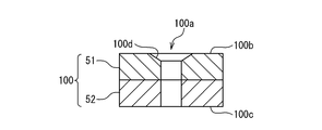
- a workpiece 100 as an object to be fastened includes a plurality of composite material parts 51 and 52 stacked.
- a countersunk hole 100a penetrating from the surface 100b on one side of the workpiece 100 to the surface 100c on the other side is formed.
- the countersink portion of the countersunk hole 100a is disposed on the surface 100b side.
- the workpiece 100 has a countersink wall surface 100d surrounding the countersink portion of the countersunk hole 100a. After the countersunk hole 100a is formed, the workpiece 100 is cleaned to remove burrs generated when the countersunk hole 100a is formed.
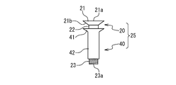
- FIG. 2 shows a fastener 25 as a fastening part for fastening the workpiece 100.
- the fastener 25 is a hack tight fastener, for example.
- the fastener 25 includes a countersunk bolt 20 and a sleeve 40.
- the countersunk bolt 20 includes a head portion 21, a cylindrical portion 22, and a screw portion 23.
- the head 21 has a head upper surface 21a and a head side surface 21b.
- the head side surface 21b is formed in a conical surface.
- the cylindrical portion 22 is disposed between the head portion 21 and the screw portion 23.
- a screw is not formed on the cylindrical portion 22.
- the screw portion 23 has an end surface 23a.
- the head upper surface 21 a and the end surface 23 a are disposed at both ends of the fastener 25 in the axial direction.
- the sleeve 40 covers the cylindrical portion 22. A portion close to the head portion 21 of the cylindrical portion 22 is exposed from the sleeve 40.
- the sleeve 40 includes a plate portion 41 disposed on the head portion 21 side and a cylindrical portion 42 disposed on the screw portion 23 side.
- the dish part 41 is formed in a conical shape.
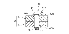
- the fastener 25 is pushed into the countersunk hole 100a until the countersink 41 abuts against the countersink wall surface 100d.
- the head portion 21 protrudes from the surface 100b and the screw portion 23 protrudes from the surface 100c in a state where the plate portion 41 is in contact with the countersink wall surface 100d.
- impact force is repeatedly applied to head upper surface 21 a using air hammer 101 to drive fastener 25.
- the nut 30 is attached to the screw portion 23 and the composite parts 51 and 52 are fastened.
- a sealant is manually brushed on the outer surface of the plate portion 41 and the cylindrical portion 42 and the head side surface 21b, and it is visually confirmed that the sealant is completely applied. Check. Since the sealant is applied manually, the operation takes time and the quality is difficult to stabilize.
- Patent Document 1 Japanese Patent Application Laid-Open No. 11-70351 discloses a seal coating apparatus that applies a sealant to a hammering hole.
- Patent Document 2 Japanese Patent Laid-Open No. 2008-302399 discloses a striking device that joins a plurality of members to be joined by rivets. With reference to FIG. 7, the chuck mechanism of this striking device will be described.
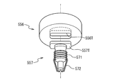
- the rivet insertion unit of the striking device includes a piston member 556 slidably provided and a rivet pressing rod 557 attached to the piston member 556.
- the rivet pressing rod 557 includes a mounting portion 557T.
- the piston member 556 is provided with a mounting hole 556T having substantially the same shape as the mounting portion 557T and capable of fitting the mounting portion 557T.
- a chuck mechanism 572 is provided at the tip of the rivet pressing rod 557. The chuck mechanism 572 can be opened and closed by the biasing force of the coil spring 571 and can grip the shaft portion of the rivet when in the closed state.
- An object of the present invention is to provide a seal coating apparatus and a seal coating method suitable for applications in which a sealant is applied to a shaft portion of a fastener.
- the seal coating device includes a fastener rotating device that rotates a fastener to which a sealant is to be applied around the central axis of the fastener.
- the fastener rotating device is connected so that torque can be transmitted to at least one of the first gripping portion and the second gripping portion for gripping the fastener in the axial direction, and the first gripping portion and the second gripping portion.
- a motor that rotates a fastener to which a sealant is to be applied around the central axis of the fastener.
- the fastener rotating device is connected so that torque can be transmitted to at least one of the first gripping portion and the second gripping portion for gripping the fastener in the axial direction, and the first gripping portion and the second gripping portion.
- the fastener rotating device includes an urging portion that urges at least one of the first gripping portion and the second gripping portion so that the first gripping portion and the second gripping portion approach each other, and the fastener And a centering mechanism for centering the fastener so that the center axis of the fastener coincides with the rotation center axis of the fastener rotating device.
- At least one of the first grip portion and the second grip portion is formed in a tapered shape that becomes narrower toward the tip.
- the seal coating device includes: a sealant discharge device that discharges the sealant; and a fastener axial direction feed device that relatively moves the fastener rotating device and the sealant discharge device in the axial direction of the fastener.
- a sealant discharge device that discharges the sealant
- a fastener axial direction feed device that relatively moves the fastener rotating device and the sealant discharge device in the axial direction of the fastener.
- the seal coating apparatus further includes a scraper.
- the scraper includes an inner surface formed so as to follow the shape of the fastener.
- the scraper is arranged such that a gap is formed between the inner surface and the fastener with the inner surface facing the fastener.
- a plurality of grooves parallel to each other are formed on the inner surface.
- the seal applicator further includes a camera for photographing the fastener set in the fastener rotating device.
- the portion of the fastener to which the sealant is applied by performing image processing on the image data generated by the camera photographing the fastener and the sealant of the fastener
- An image processing apparatus for detecting an uncoated portion is further provided.
- a seal coating method comprises applying a sealant to the fastener while rotating the fastener around the central axis of the fastener while gripping the fastener in the axial direction of the fastener. To do.
- the first gripping portion and the second gripping portion rotate the fastener while the fastener is gripped in the axial direction.
- a motor is connected to at least one of the first gripping portion and the second gripping portion so that torque can be transmitted.
- the fastener is centered so that the central axis of the fastener coincides with the rotation central axis in a state where the first gripping portion and the second gripping portion grip the fastener. It further comprises. In the centering, the fastener is centered while urging at least one of the first gripping part and the second gripping part so that the first gripping part and the second gripping part come closer to each other. .
- applying the sealant comprises discharging the sealant from a nozzle and relatively moving the nozzle and the fastener in the axial direction of the fastener.
- applying the sealant includes extending the sealant on the fastener using a scraper.
- the seal coating method further includes photographing the fastener at a plurality of different rotational positions.
- image data of the fastener is generated by photographing the fastener at a plurality of different rotational positions.
- image processing is performed on the image data to detect a portion of the fastener where the sealant is applied and a portion of the fastener where the sealant is not applied. Is further provided.
- a seal coating apparatus and a seal coating method suitable for applications in which a sealant is applied to the shaft portion of a fastener.
- FIG. 1 is a cross-sectional view of a workpiece showing a state in which a countersunk hole is formed.
- FIG. 2 shows a fastener for fastening a workpiece.
- FIG. 3 is a cross-sectional view of the workpiece showing a state in which the fastener is pushed into the countersunk hole.
- FIG. 4 is a cross-sectional view of the workpiece showing a state in which a fastener is driven using an air hammer.
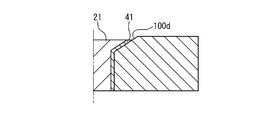
- FIG. 5 is a cross-sectional view of the workpiece showing a state where the fastener has been driven.
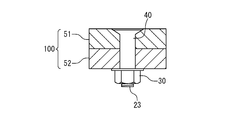
- FIG. 6 is a cross-sectional view of a workpiece showing a state where a nut is attached to a fastener.
- FIG. 7 is a perspective view of the chuck mechanism of the striking device.
- FIG. 8 is a schematic view of a seal coating apparatus according to the first embodiment of the present invention.
- FIG. 9 is a schematic view of a centering mechanism provided in the seal coating apparatus.
- FIG. 10 is a block diagram of a control system of the seal coating apparatus.
- FIG. 11A is a conceptual diagram for explaining a step of setting a fastener on a fastener rotating device provided in the seal coating apparatus.
- FIG. 11B is a conceptual diagram for explaining a step of setting a fastener in a fastener rotating device provided in the seal coating apparatus.
- FIG. 11A is a conceptual diagram for explaining a step of setting a fastener on a fastener rotating device provided in the seal coating apparatus.
- FIG. 11B is a conceptual diagram for explaining a step
- FIG. 11C is a conceptual diagram for explaining a step of setting a fastener on a fastener rotating device provided in the seal coating apparatus.
- FIG. 11D is a conceptual diagram for explaining a step of setting a fastener in a fastener rotating device provided in the seal coating apparatus.
- FIG. 12 is a conceptual diagram for explaining a step of applying a sealing agent to the fastener.
- FIG. 13 is a graph showing the relationship between the outer diameter of the fastener and the number of rotations of the fastener, and the relationship between the outer diameter of the fastener and the feed rate in the fastener axial direction.
- FIG. 14 is a schematic diagram showing a positional relationship between a nozzle that discharges a sealing agent and a fastener.
- FIG. 15 is a schematic view showing a positional relationship between a scraper and a fastener provided in the seal coating apparatus according to the second embodiment of the present invention.
- FIG. 16 is a cross-sectional view of the scraper.
- FIG. 17 is a block diagram of a seal application state confirmation apparatus provided in a seal application apparatus according to the third embodiment of the present invention.
- FIG. 18 is a schematic view showing the positional relationship between the camera and the fastener of the seal application state confirmation device.
- the seal application device 1 automatically applies a sealant to the shaft portion of the fastener 25.
- the fastener 25 may be a rivet or a bolt.
- An X axis, a Y axis, and a Z axis that are orthogonal to each other are defined for the seal coating apparatus 1.
- the X axis and the Y axis form a horizontal plane.
- the seal application device 1 includes a base 10, a sealant discharge device 11, a fastener rotating device 12, and a fastener axial direction feeding device 13.
- the sealing agent discharge device 11 discharges the sealing agent to be applied to the fastener 25.
- the sealant discharge device 11 includes a discharge punch 111, a seal cartridge 112, a nozzle 112a, a discharge punch feeding device 113, a reaction force sensor 116, and a support structure 117.
- the support structure 117 supports the seal cartridge 112 and the discharge punch feeder 113 at a position above the base 10.
- the seal cartridge 112 is filled with a sealant to be applied to the fastener 25.
- the nozzle 112 a is connected to the seal cartridge 12.
- the axial direction of the nozzle 112a and the axial direction of the seal cartridge 12 are parallel to the Z axis.
- the discharge punch feeder 113 includes a servo motor 114 and a ball screw 115.
- the discharge punch feeder 113 moves the discharge punch 111 parallel to the Z axis and pushes it into the seal cartridge 112.
- the sealant is discharged from the nozzle 112a.
- the reaction force sensor 116 is a load cell or a piezoelectric element that detects a pressing reaction force acting on the discharge punch 111.
- the pressure sensor 116 may be configured to detect the pushing reaction force based on the motor current value of the servo motor 114.
- the fastener rotating device 12 rotates the fastener 25 around the central axis of the fastener 25.
- the central axis of the fastener 25 is parallel to the axial direction of the fastener 25.
- the fastener 25 is set in the fastener rotating device 12 so that the center axis of the fastener 25 is parallel to the Y axis.
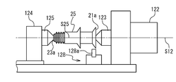
- the fastener rotating device 12 includes a rotating device base 121, a motor 122, a gripping portion 123, a core pushing stand 124, a gripping portion 125, a biasing portion 126, a linear motion guide 127, and a centering mechanism 128. Prepare.
- the motor 122 is fixed to the rotating device base 121.
- the shaft of the motor 122 is parallel to the Y axis.
- the grip portion 123 is connected to the shaft of the motor 122 so that torque can be transmitted.
- the linear motion guide 127 guides the core pushing table 124 in parallel to the Y axis with respect to the rotating device base 121.
- the core push stand 124 supports the grip portion 125 so that the grip portion 125 can rotate around a rotation axis parallel to the Y axis.
- the grip portions 123 and 125 are arranged on the same straight line parallel to the Y axis so as to face each other.
- the urging portion 126 urges the core push stand 124 so that the grip portion 125 approaches the grip portion 123, whereby the grip portions 123 and 125 grip the fastener 25 in the axial direction of the fastener 25. That is, the grip portions 123 and 125 grip the fastener 25 in a state where the grip portion 123 is in contact with the top surface 21a of the fastener 25 and the grip portion 125 is in contact with the end surface 23a.
- the grip part 123 and the grip part 125 are formed in a tapered shape that becomes narrower toward the tip.
- the urging unit 126 includes an actuator or a spring that urges the core pushing table 124.
- the urging unit 126 urges the core pushing table 124 while allowing the movement of the core pushing table 124 and the holding unit 125 toward and away from the holding unit 123.
- the centering mechanism 128 centers the fastener 25 so that the center axis of the fastener 25 coincides with the rotation center axis of the fastener rotating device 12 (the rotation axis of the gripping portions 123 and 125).
- the motor 122 rotates the grip part 123. Thereby, the fastener 25 and the holding part 125 also rotate.
- the centering mechanism 128 includes a plurality of contact portions 128a.
- the contact portion 128a is also referred to as a centering finger.
- the plurality of contact portions 128a are movable in a plane perpendicular to the Y axis.
- the fasteners 25 are centered so that the plurality of contact portions 128 a come into contact with the head 21 of the fastener 25 and the center axis of the fastener 25 coincides with the rotation center axis of the fastener rotating device 12.
- the fastener axial direction feeding device 13 moves the fastener rotating device 12 parallel to the Y axis.
- the fastener axial direction feeding device 13 includes a cylinder 131 and a linear motion guide 132.
- the linear motion guide 132 guides the rotation device base 121 in parallel to the Y axis with respect to the base 10.
- the cylinder 131 moves the rotating device base 121 parallel to the Y axis with respect to the base 10.
- the seal application device 1 includes a controller 14.
- the controller 14 inputs the fastener shape data FSD, the discharge punch feed speed set value V1 *, the fastener peripheral speed set value CS *, and the lead set value L *, and the discharge punch feed device 13, the fastener rotating device 12, and the fastener shaft.
- the direction feeder 13 is controlled.
- the fastener shape data FSD describes the relationship between the position in the axial direction of the fastener 25 and the outer diameter at the site (the sleeve 40 and the head side surface 21b) to which the sealant is to be applied.
- the discharge punch feed speed setting value V1 * is a constant for setting the feed speed of the discharge punch 111.
- the fastener peripheral speed setting value CS * is a constant that sets the peripheral speed of the part of the fastener 25 where the axial position of the fastener 25 coincides with the nozzle 112a.
- the lead set value L * is a constant that sets a distance that the fastener rotating device 12 and the sealant discharging device 11 move relatively in the axial direction of the fastener 25 while the fastener 25 makes one rotation.
- the fastener 25 is set on the fastener rotating device 12.
- the gap between the grip portions 123 and 125 is longer than the axial length of the fastener 25.
- the plurality of contact portions 128a of the centering mechanism 128 are open.
- the rotation center axis of the fastener rotating device 12 is indicated by reference numeral S12
- the center axis of the fastener 25 is indicated by reference numeral S25.
- the conveying device 200 conveys the fastener 25 between the gripping portions 123 and 125, and the fastener 25 is delivered from the conveying device 200 to the fastener rotating device 12.
- the gripping portions 123 and 125 grip the fastener 25 in the axial direction in a state where the biasing portion 126 biases the core pushing table 124 and the gripping portion 125 so that the gripping portions 123 and 125 approach each other.
- the tip of the gripper 123 contacts the head upper surface 21a
- the tip of the gripper 125 contacts the end surface 23a.
- the fastener center axis S25 does not coincide with the rotation center axis S12.
- the plurality of abutting portions 128a included in the centering mechanism 128 are closed to contact the head 21 of the fastener 25, and the center of the fastener 25 is aligned with the center axis S25 of the fastener.
- the core push table 124 and the gripping portion 125 are biased toward the gripping portion 123 but can advance and retreat in parallel with the Y axis. Therefore, the positions of the core push stand 124 and the gripping portion 125 are appropriate positions. Adjusted to.
- the plurality of contact portions 128 a included in the centering mechanism 128 are opened and separated from the fastener 25.
- the fastener rotating device 12 rotates the fastener 25
- the plurality of contact portions 128 a are kept away from the fastener 25.
- the seal coating device 1 discharges the sealing agent from the nozzle 112a at a fixed discharge amount, rotates the fastener 25 around the fastener central axis S25, and relatively moves the nozzle 112a and the fastener 25 in the axial direction of the fastener 25. A sealant is applied to the fastener 25 while being moved.
- the controller 14 controls the discharge punch feeding device 13 so that the discharge punch 111 is pushed into the seal cartridge 112 at a constant discharge punch feed speed V1 that matches the discharge punch feed speed setting value V1 *.
- the sealing agent is discharged from the nozzle 112a at a constant discharge amount.
- the sealant 300 is discharged at a constant thickness W and at a constant discharge speed V2.
- the above-mentioned fastener peripheral speed set value CS * is determined in advance so as to correspond to the sealant discharge speed V2.
- the lead set value L * is determined in advance so as to correspond to the sealant thickness W.
- the controller 14 Based on the fastener shape data FSD, the controller 14 sets the fastener rotating device 12 so that the peripheral speed of the portion of the fastener 25 where the axial position of the fastener 25 coincides with the nozzle 112a is constant at the fastener peripheral speed setting value CS *. In the axial direction of the fastener so that the distance that the fastener rotating device 12 and the sealant discharging device 11 move relatively in the axial direction of the fastener 25 is constant at the lead set value L * while the fastener 25 rotates once.
- the feeding device 13 is controlled.
- the fastener rotating device 12 keeps the rotational speed RS of the fastener 25 constant, and the fastener axial direction feeding device. 13 keeps the feed speed Vy in the axial direction of the fastener 25 of the fastener rotating device 12 constant.
- the sealing agent is applied to the plate portion 41 and the head side surface 21b whose outer diameter changes along the axial direction of the fastener 25, the fastener rotating device 12 changes the fastener rotational speed RS, and the fastener axial direction feeding device 13 is applied. Changes the fastener axial feed speed Vy.
- FIG. 13 shows the relationship between the outer diameter of the portion of the fastener 25 where the axial position of the fastener 25 matches the nozzle 112a and the fastener rotation speed RS, and the fastener 25 where the axial position of the fastener 25 matches the nozzle 112a.
- part and the fastener axial direction feed speed Vy is shown. That is, when the outer diameter of the part of the fastener 25 where the position of the fastener 25 in the axial direction coincides with the nozzle 112a increases along the axial direction of the fastener 25, the fastener rotational speed RS and the fastener axial feed speed Vy decrease.
- the fastener rotation speed RS and the fastener axial feed speed Vy increase.
- the control for simultaneously decreasing the fastener rotational speed RS and the fastener axial feed speed Vy and the control for simultaneously increasing the fastener rotational speed RS and the fastener axial feed speed Vy are conical surfaces such as the plate portion 41 and the head side surface 21b. It is suitable when the sealing agent is uniformly applied to the surface.
- FIG. 14 shows a cross section perpendicular to the rotation center axis S12 (fastener center axis S25) at the position of the nozzle 112a.
- the angle ⁇ is a circumferential velocity vector 402 indicating the circumferential velocity of the fastener 25 at a point P closest to the nozzle 112a among the intersections between the central axis S112 of the nozzle 112a and the outer surface of the fastener 25, and a seal discharged from the nozzle 112a.
- This is an angle formed with a discharge direction vector 401 indicating the discharge direction of the agent.
- the nozzle center axis S112 may be parallel to the Z axis as shown, or may be inclined with respect to the Z axis in a plane perpendicular to the rotation center axis S12 (fastener center axis S25). Although the coating quality of the sealant is relatively poor, the nozzle center axis S112 may pass through the rotation center axis S12 (fastener center axis S25).
- the gripping portions 123 and 125 grip the fastener 25 in the axial direction. More specifically, the gripping portions 123 and 125 grip the fastener 25 so that the tip of the gripping portion 123 contacts the head upper surface 21b and the tip of the gripping portion 125 contacts the end surface 23a. Therefore, in principle, it is possible to apply the sealing agent so that there is no unpainted area on the entire circumference of the shaft portion of the fastener 25. Therefore, the seal application device 1 and the seal application method according to the present embodiment are suitable for applications in which a sealant is applied to the shaft portion of the fastener 25. Furthermore, the centering mechanism 128 can ensure that the fastener center axis S25 coincides with the rotation center axis S12.
- the contact portion 128a used for centering the fastener 25 is in a state separated from the fastener 25. Therefore, the contact part 128a does not interfere with the application of the sealing agent. Further, since the gripping portions 123 and 125 are tapered, the sealing agent adheres to the gripping portions 123 and 125 even when the sealing agent is applied to the end portion (for example, the head side surface 21b) of the fastener 25. Is prevented.
- Sealant is generally a high-viscosity fluid that cures over time (viscosity increases).
- the pressing force of the discharge punch 111 is controlled to be constant, the sealant cannot be quantitatively discharged. Therefore, it is difficult to apply the sealing agent to the fastener 25 uniformly.
- the discharge amount of the sealing agent is controlled to be constant because the discharge punch feeding device 113 changes the push force of the discharge punch 111 so that the push speed of the discharge punch 111 is constant. Therefore, it is easy to apply the sealing agent to the fastener 25 uniformly.
- the quality of the sealing agent applied to the fastener 25 can be controlled by detecting the pushing reaction force acting on the discharge punch 111 when the sealing agent is discharged by the reaction force sensor 116.
- the core push table 124 and the grip portion 125 are movable in parallel to the Y axis with respect to the rotating device base 121, and the motor 122 and the grip portion 123 are immovable in the Y axis direction with respect to the rotating device base 121.
- the urging unit 126 urges the core pushing table 124 and the gripping part 125 so that the gripping parts 123 and 125 come close to each other.
- the core push table 124 and the grip portion 125 are immovable in parallel with the Y axis with respect to the rotating device base 121, and the motor 122 and the grip portion 123 are movable with respect to the rotating device base 121 in the Y axis direction.
- the biasing part 126 may bias the motor 122 and the gripping part 123 so that the gripping parts 123 and 125 are close to each other.
- the fastener rotating device 12 (more specifically, the rotating device base 121) is movable in parallel to the Y axis with respect to the base 10, and the sealant discharging device 11 is parallel to the Y axis with respect to the base 10.
- the cylinder 131 moves in the fastener rotating device 12 (more specifically, the rotating device base 121) parallel to the Y axis.
- the fastener rotating device 12 (more specifically, the rotating device base 121) is immovable in parallel to the Y axis with respect to the base 10, and the sealant discharging device 11 is movable in parallel to the Y axis with respect to the base 10.
- the cylinder 131 may move the sealant discharge device 11 parallel to the Y axis.
- seal coating apparatus 1 and a seal coating method according to the second embodiment of the present invention will be described.
- the seal coating apparatus 1 and the seal coating method according to the second embodiment are the same as those of the first embodiment except for the following description.
- the seal application device 1 includes a scraper 15.
- the scraper 15 is formed so as to correspond to the shape of the part to which the sealant of the fastener 25 is to be applied.
- the scraper 15 is formed in a shape obtained by vertically dividing a cylindrical body with a conical portion along the shape of the sleeve 40.
- the scraper 15 includes a partial conical portion 151 corresponding to the dish portion 41 and a partial cylindrical portion 152 corresponding to the cylindrical portion 42.
- the inner side surface 151 a of the partial cone portion 151 is formed so as to follow the shape of the dish portion 41.
- the inner side surface 152 a of the partial cylindrical portion 152 is formed so as to follow the shape of the cylindrical portion 42.
- a plurality of grooves 152b parallel to each other are formed on the inner surface 152a.
- the plurality of grooves 152b are spiral groove portions formed on the inner surface of the cylindrical portion of the cylindrical body with the conical portion.
- the scraper 15 has gaps between the inner side surface 151a and the plate portion 41 and between the inner side surface 152a and the cylindrical portion 42, with the inner side surface 151a facing the plate portion 41 and the inner side surface 152a facing the cylindrical portion 42. It is attached to the rotating device base 121 so as to be formed.
- the sealant on the sleeve 40 is extended by the scraper 15. Therefore, the coating film of the sealing agent can be thinned. Further, even when air is mixed in the seal cartridge 112, it is possible to prevent a portion where the sealant is not applied on the surface of the sleeve 40 (a paint leakage portion).
- the plurality of grooves 152b on the inner surface 152a have the following effects. If the plurality of grooves 152b are not provided, the sealing agent that should have protruded to the outside of the scraper 15 is filled in the plurality of grooves 152b and applied to the fasteners 25, so that many fasteners 25 can be applied with a small amount of sealing agents.
- a groove may be formed on the inner surface 151a.
- the gap between the scraper 15 and the fastener 25 can be reduced to further reduce the coating film of the sealant.
- a corrugated scraper, brush, or spatula may be used in place of the scraper 15.
- the seal application device 1 includes a seal application state confirmation device 16.
- the seal application state confirmation device 16 includes a camera 161, an image processing device 162, an output device 163, and a storage device 164.
- the camera 161 shoots the fastener 25 in a state of being set on the fastener rotating device 12 (state of being gripped by the gripping portions 123 and 125) and generates image data.
- the fastener rotating device 12 rotates the fastener 25
- the fastener 25 can be photographed at a plurality of different rotational positions. Therefore, it is possible to confirm the application state of the sealant around the entire periphery of the fastener 25.
- the image processing apparatus 162 performs image processing on the image data generated by the camera 161, and a portion where the sealant of the fastener 25 is applied (application portion) and a portion where the sealant of the fastener 25 is not applied ( Detect smeared part).
- application portion a portion where the sealant of the fastener 25 is applied
- Detect smeared part a portion where the sealant of the fastener 25 is not applied.
- the output device 163 outputs an error when a smeared portion is detected. In this case, a sealant is manually applied to the paint leakage portion.
- the output device 163 may output an image of the fastener 25 before image processing or an image of the fastener 25 after image processing.
- the storage device 164 records the image data before image processing, the image data after image processing, and the detection results of the application portion and the smeared portion in association with the identifier of the fastener 25. These are used for quality control and the like.
- centering mechanism 128 that centers the fastener 25 so that the fastener central axis S25 matches the rotational center axis S12 of the fastener rotating device 12 by contacting the screw portion 23 or the cylindrical portion 42 of the fastener 25 is added. May be.
Landscapes
- Engineering & Computer Science (AREA)
- General Engineering & Computer Science (AREA)
- Coating Apparatus (AREA)
- Mechanical Engineering (AREA)
- Application Of Or Painting With Fluid Materials (AREA)
Abstract
ファスナー(25)を軸方向に把持する第1把持部(123)及び第2把持部(125)と、第1把持部(123)及び第2把持部(125)の少なくとも一方に対してトルクが伝達可能に接続されたモータ(122)とを備えるファスナー回転装置(12)を具備するシール塗布装置(1)において、ファスナー(25)の中心軸まわりにファスナー(25)を回転させながら、シール剤を塗布するものである。 当該構成により、ファスナーの軸部にシール剤を塗布できる。
Description
本発明は、ボルトやリベットのようなファスナー(締結部品)を用いて被締結物を締結する技術に関し、特に締結部をシールする技術に関する。
ボルトやリベットのようなファスナー(締結部品)を用いて被締結物を締結する技術は、航空機等の組立てに利用されている。ファスナーを用いて航空機の主翼の部品を締結する場合、燃料漏れを防ぐために締結部をシールする。
図1~6を参照して、繊維強化プラスチックのような複合材の被締結物を手作業で締結する方法を説明する。
図1を参照して、被締結物としてのワーク100は、重ねられた複数の複合材部品51及び52を含む。ワーク100の一方側の表面100bから他方側の表面100cへ貫通する皿穴付き孔100aを形成する。皿穴付き孔100aの皿穴部分は表面100b側に配置される。ワーク100は、皿穴付き孔100aの皿穴部分を囲む皿穴壁面100dを有する。皿穴付き孔100aの形成後、ワーク100を清掃して皿穴付き孔100aを形成したときに生じたバリを取り除く。
図2は、ワーク100を締結するための締結部品としてのファスナー25を示す。ファスナー25は、例えば、ハックタイトファスナーである。ファスナー25は、皿ボルト20と、スリーブ40とを備える。皿ボルト20は、頭部21と、円筒部22と、ねじ部23とを備える。頭部21は、頭部上面21aと、頭部側面21bとを有する。頭部側面21bは円錐面に形成されている。円筒部22は、頭部21とねじ部23の間に配置される。円筒部22にはねじが形成されていない。ねじ部23は、端面23aを有する。頭部上面21a及び端面23aは、ファスナー25の軸方向の両端に配置される。スリーブ40は、円筒部22に被せられている。円筒部22の頭部21に近い部分がスリーブ40から露出している。スリーブ40は、頭部21側に配置された皿部41と、ねじ部23側に配置された円筒部42とを備える。皿部41は円錐形状に形成されている。
図3を参照して、皿部41が皿穴壁面100dに突き当たるまで、ファスナー25を皿穴付孔100aに押し込む。皿部41が皿穴壁面100dに接触した状態で、頭部21は表面100bから突き出しており、ねじ部23は表面100cから突き出している。
図4を参照して、エアーハンマー101を用いて頭部上面21aに衝撃力を繰り返し付与してファスナー25を打ち込む。
図5を参照して、ファスナー25がワーク100に着座するまで、すなわち頭部21が皿部41を介して皿穴壁面100dに突き当たるまで、エアーハンマー101を用いて頭部上面21aに衝撃力を繰り返し付与する。ここで、ファスナー25が着座したことを作業者が音で判断してエアーハンマー101による衝撃力の付与を停止する。
図6を参照して、ナット30をねじ部23に装着して複合材部品51及び52を締結する。
ここで、締結部をシールするため、皿部41及び円筒部42の外側面と、頭部側面21bとにシール剤を手作業で刷毛塗りし、シール剤が完全に塗布されたことを目視で確認する。シール剤を手作業で塗布しているため、作業に時間がかかり、且つ、品質が安定しにくい。
本発明に関連して、特許文献1(特開平11-70351号公報)は、打鋲穴にシール剤を塗布するシール塗布装置を開示している。
本発明に関連して、特許文献2(特開2008-302399号公報)は、複数の被結合部材をリベットにより結合させる打鋲装置を開示している。図7を参照して、この打鋲装置のチャック機構を説明する。打鋲装置のリベット挿入ユニットは、摺動可能に設けられたピストン部材556と、ピストン部材556に取り付けられるリベット押圧ロッド557とを備える。リベット押圧ロッド557は、取付部557Tを備える。ピストン部材556は、取付部557Tと略同一形状で取付部557Tを嵌め合わすことができる取付穴556Tを備える。リベット押圧ロッド557の先端にチャック機構572が設けられる。チャック機構572は、コイルバネ571の付勢により開閉可能とされ、閉状態となることでリベットの軸部を把持可能である。
本発明の目的は、ファスナーの軸部にシール剤を塗布する用途に好適なシール塗布装置及びシール塗布方法を提供することである。
本発明の第1の観点によるシール塗布装置は、シール剤が塗布されるべきファスナーを前記ファスナーの中心軸まわりに回転するファスナー回転装置を具備する。前記ファスナー回転装置は、前記ファスナーを軸方向に把持する第1把持部及び第2把持部と、前記第1把持部及び前記第2把持部の少なくとも一方に対してトルクが伝達可能に接続されたモータとを備える。
好ましくは、前記ファスナー回転装置は、前記第1把持部及び前記第2把持部が互いに近づくように前記第1把持部及び前記第2把持部の少なくとも一方を付勢する付勢部と、前記ファスナーの前記中心軸が前記ファスナー回転装置の回転中心軸に一致するように前記ファスナーの芯出しをする芯出し機構とを備える。
好ましくは、前記第1把持部及び前記第2把持部の少なくとも一方は、先端に向かって細くなるテーパー形状に形成される。
好ましくは、上記シール塗布装置は、前記シール剤を吐出するシール剤吐出装置と、前記ファスナー回転装置及び前記シール剤吐出装置を前記ファスナーの軸方向に相対的に移動するファスナー軸方向送り装置とを更に具備する。
好ましくは、上記シール塗布装置は、スクレーパを更に具備する。前記スクレーパは、前記ファスナーの形状に沿うように形成された内側面を備える。前記スクレーパは、前記内側面が前記ファスナーを向いた状態で前記内側面と前記ファスナーとの間に隙間が形成されるように配置される。
好ましくは、前記内側面に互いに平行な複数の溝が形成される。
好ましくは、上記シール塗布装置は、前記ファスナー回転装置にセットされた状態の前記ファスナーを撮影するカメラを更に具備する。
好ましくは、上記シール塗布装置は、前記カメラが前記ファスナーを撮影して生成した画像データに対して画像処理を実行して前記ファスナーの前記シール剤が塗布された部分と前記ファスナーの前記シール剤が塗布されていない部分とを検出する画像処理装置を更に具備する。
本発明の第2の観点によるシール塗布方法は、ファスナーの軸方向に前記ファスナーを把持した状態で前記ファスナーの中心軸まわりに前記ファスナーを回転させながら、前記ファスナーにシール剤を塗布することを具備する。
好ましくは、前記シール剤を塗布することにおいて、第1把持部及び第2把持部が前記ファスナーを前記軸方向に把持した状態で前記ファスナーを回転させる。前記第1把持部及び前記第2把持部の少なくとも一方に対してモータがトルクの伝達が可能に接続される。好ましくは、上記シール塗布方法は、前記第1把持部及び前記第2把持部が前記ファスナーを把持した状態で前記ファスナーの前記中心軸が回転中心軸に一致するように前記ファスナーの芯出しをすることを更に具備する。前記芯出しをすることにおいて、前記第1把持部及び前記第2把持部が互いに近づくように前記第1把持部及び前記第2把持部の少なくとも一方を付勢しながら前記ファスナーの芯出しを行う。
好ましくは、前記シール剤を塗布することは、前記シール剤をノズルから吐出することと、前記ノズル及び前記ファスナーを前記ファスナーの軸方向に相対的に移動することとを備える。
好ましくは、前記シール剤を塗布することは、スクレーパを用いて前記シール剤を前記ファスナー上で伸ばすことを含む。
好ましくは、上記シール塗布方法は、前記ファスナーを互いに異なる複数の回転位置において撮影することを更に具備する。
好ましくは、前記ファスナーを互いに異なる複数の回転位置において撮影することにおいて、前記ファスナーの画像データを生成する。好ましくは、上記シール塗布方法は、前記画像データに対して画像処理を実行して前記ファスナーの前記シール剤が塗布された部分と前記ファスナーの前記シール剤が塗布されていない部分とを検出することを更に具備する。
本発明によれば、ファスナーの軸部にシール剤を塗布する用途に好適なシール塗布装置及びシール塗布方法が提供される。
本発明の上記目的、他の目的、効果、及び特徴は、添付される図面として連携して実施の形態の記述から、より明らかになる。
図1は、皿穴付き孔が形成された状態を示すワークの断面図である。
図2は、ワークを締結するためのファスナーを示す。
図3は、皿穴付き孔にファスナーを押し込んだ状態を示すワークの断面図である。
図4は、エアーハンマーを用いてファスナーを打ち込んでいる状態を示すワークの断面図である。
図5は、ファスナーの打ち込みが完了した状態を示すワークの断面図である。
図6は、ファスナーにナットを装着した状態を示すワークの断面図である。
図7は、打鋲装置のチャック機構の斜視図である。
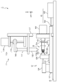
図8は、本発明の第1の実施形態に係るシール塗布装置の概略図である。
図9は、シール塗布装置が備える芯出し機構の概略図である。
図10は、シール塗布装置の制御系のブロック図である。
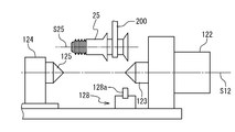
図11Aは、シール塗布装置が備えるファスナー回転装置にファスナーをセットするステップを説明するための概念図である。
図11Bは、シール塗布装置が備えるファスナー回転装置にファスナーをセットするステップを説明するための概念図である。
図11Cは、シール塗布装置が備えるファスナー回転装置にファスナーをセットするステップを説明するための概念図である。
図11Dは、シール塗布装置が備えるファスナー回転装置にファスナーをセットするステップを説明するための概念図である。
図12は、ファスナーにシール剤を塗布するステップを説明するための概念図である。
図13は、ファスナー外径とファスナー回転数の関係及びファスナー外径とファスナー軸方向送り速度の関係を示すグラフである。
図14は、シール剤を吐出するノズルとファスナーとの位置関係を示す概略図である。
図15は、本発明の第2の実施形態に係るシール塗布装置が備えるスクレーパとファスナーとの位置関係を示す概略図である。
図16は、スクレーパの断面図である。
図17は、本発明の第3の実施形態に係るシール塗布装置が備えるシール塗布状態確認装置のブロック図である。
図18は、シール塗布状態確認装置のカメラとファスナーとの位置関係を示す概略図である。
添付図面を参照して、本発明によるシール塗布装置及びシール塗布方法を実施するための形態を以下に説明する。
(第1の実施形態)
図8を参照して、本発明の第1の実施形態に係るシール塗布装置1を説明する。シール塗布装置1は、ファスナー25の軸部にシール剤を自動で塗布する。ここでは、ファスナー25が上述のハックタイトファスナーの場合について説明するが、ファスナー25はリベットでもよく、ボルトでもよい。シール塗布装置1に対して、互いに直交するX軸、Y軸、及びZ軸が定義される。例えば、X軸及びY軸は水平面を形成する。シール塗布装置1は、ベース10と、シール剤吐出装置11と、ファスナー回転装置12と、ファスナー軸方向送り装置13とを備える。
図8を参照して、本発明の第1の実施形態に係るシール塗布装置1を説明する。シール塗布装置1は、ファスナー25の軸部にシール剤を自動で塗布する。ここでは、ファスナー25が上述のハックタイトファスナーの場合について説明するが、ファスナー25はリベットでもよく、ボルトでもよい。シール塗布装置1に対して、互いに直交するX軸、Y軸、及びZ軸が定義される。例えば、X軸及びY軸は水平面を形成する。シール塗布装置1は、ベース10と、シール剤吐出装置11と、ファスナー回転装置12と、ファスナー軸方向送り装置13とを備える。
シール剤吐出装置11はファスナー25に塗布されるべきシール剤を吐出する。シール剤吐出装置11は、吐出パンチ111と、シールカートリッジ112と、ノズル112aと、吐出パンチ送り装置113と、反力センサ116と、支持構造117とを備える。支持構造117は、シールカートリッジ112及び吐出パンチ送り装置113をベース10の上方位置で支持する。シールカートリッジ112にはファスナー25に塗布されるべきシール剤が充填されている。ノズル112aはシールカートリッジ12に接続されている。ノズル112aの軸方向及びシールカートリッジ12の軸方向はZ軸に平行である。吐出パンチ送り装置113は、サーボモータ114と、ボールネジ115とを備える。吐出パンチ送り装置113は、吐出パンチ111をZ軸に平行に動かしてシールカートリッジ112に押し込む。吐出パンチ111がシールカートリッジ112に押し込まれることで、ノズル112aからシール剤が吐出される。サーボモータ114の回転数が一定になるようにフィードバック制御を実行することで、吐出パンチ送り装置113は吐出パンチ111をシールカートリッジ112に一定速度で押し込む。反力センサ116は、吐出パンチ111に作用する押し込み反力を検出するロードセル又は圧電素子である。或いは、圧力センサ116は、サーボモータ114のモータ電流値に基づいて押し込み反力を検出するように構成されてもよい。
ファスナー回転装置12は、ファスナー25をファスナー25の中心軸まわりに回転する。ファスナー25の中心軸はファスナー25の軸方向に平行である。ファスナー25は、ファスナー25の中心軸がY軸に平行になるようにファスナー回転装置12にセットされる。ファスナー回転装置12は、回転装置ベース121と、モータ122と、把持部123と、芯押し台124と、把持部125と、付勢部126と、直動ガイド127と、芯出し機構128とを備える。モータ122は、回転装置ベース121に対して固定される。モータ122のシャフトはY軸に平行である。把持部123は、モータ122のシャフトに対してトルクが伝達可能に接続される。直動ガイド127は、芯押し台124を回転装置ベース121に対してY軸に平行に案内する。芯押し台124は、把持部125がY軸に平行な回転軸まわりに回転可能なように把持部125を支持する。把持部123及び125は、互いに向かい合うようにY軸に平行な同一直線上に配置される。把持部125が把持部123に近づくように付勢部126が芯押し台124を付勢することで、把持部123及び125は、ファスナー25をファスナー25の軸方向に把持する。すなわち、把持部123及び125は、把持部123がファスナー25の頭部上面21aに接触し、把持部125が端面23aに接触した状態で、ファスナー25を把持する。把持部123及び把持部125は、先端に向かって細くなるテーパー形状に形成される。尚、把持部123及び把持部125の先端は、ファスナー25のキズ防止及びファスナー25の表面処理の剥離防止のために適度に面取りしてある。付勢部126は、芯押し台124を付勢するアクチュエータ又はばねを備える。付勢部126は、芯押し台124及び把持部125の把持部123に近づく移動及び遠ざかる移動を許容しながら、芯押し台124を付勢する。芯出し機構128は、ファスナー25の中心軸がファスナー回転装置12の回転中心軸(把持部123及び125の回転軸)に一致するようにファスナー25の芯出しをする。モータ122は、把持部123を回転させる。これにより、ファスナー25及び把持部125も回転する。
図9を参照して、芯出し機構128は、複数の当接部128aを備える。当接部128aは芯出しフィンガーとも称される。複数の当接部128aはY軸に垂直な面内を可動である。複数の当接部128aがファスナー25の頭部21に接触してファスナー25の中心軸がファスナー回転装置12の回転中心軸に一致するようにファスナー25の芯出しをする。
図8を参照して、ファスナー軸方向送り装置13は、ファスナー回転装置12をY軸に平行に移動する。ファスナー軸方向送り装置13は、シリンダー131と、直動ガイド132とを備える。直動ガイド132は、回転装置ベース121をベース10に対してY軸に平行に案内する。シリンダー131は、回転装置ベース121をベース10に対してY軸に平行に移動する。
図10を参照して、シール塗布装置1はコントローラ14を備える。コントローラ14は、ファスナー形状データFSD、吐出パンチ送り速度設定値V1*、ファスナー周速度設定値CS*、及びリード設定値L*を入力し、吐出パンチ送り装置13、ファスナー回転装置12、及びファスナー軸方向送り装置13を制御する。ファスナー形状データFSDは、シール剤が塗布されるべき部位(スリーブ40及び頭部側面21b)におけるファスナー25の軸方向の位置と外径との関係を記述する。吐出パンチ送り速度設定値V1*は、吐出パンチ111の送り速度を設定する定数である。ファスナー周速度設定値CS*は、ファスナー25の軸方向の位置がノズル112aに一致するファスナー25の部位の周速度を設定する定数である。リード設定値L*は、ファスナー25が一回転する間にファスナー回転装置12及びシール剤吐出装置11がファスナー25の軸方向に相対的に移動する距離を設定する定数である。
以下、シール塗布装置1を用いたシール塗布方法を説明する。はじめにファスナー回転装置12にファスナー25をセットする。
図11Aを参照して、把持部123及び125の間隔は、ファスナー25の軸方向の長さよりも離れている。芯出し機構128の複数の当接部128aは開いている。ファスナー回転装置12の回転中心軸が符号S12で示され、ファスナー25の中心軸が符号S25で示されている。搬送装置200がファスナー25を把持部123及び125の間に搬送し、ファスナー25が搬送装置200からファスナー回転装置12に引き渡される。
図11Bを参照して、付勢部126が把持部123及び125が互いに近づくように芯押し台124及び把持部125を付勢した状態で、把持部123及び125がファスナー25を軸方向に把持する。ここで、把持部123の先端が頭部上面21aに接触し、把持部125の先端が端面23aに接触する。この段階では、ファスナー中心軸S25は回転中心軸S12と一致していない。
図11Cを参照して、芯出し機構128が備える複数の当接部128aが閉じてファスナー25の頭部21に接触し、ファスナー中心軸S25が回転中心軸S12に一致するようにファスナー25の芯出しをする。このとき、芯押し台124及び把持部125は、把持部123に向かって付勢されているもののY軸に平行に進退可能であるため、芯押し台124及び把持部125の位置が適切な位置に調節される。
図11Dを参照して、芯出し機構128が備える複数の当接部128aが開いてファスナー25から離れる。ファスナー回転装置12がファスナー25を回転するとき、複数の当接部128aはファスナー25から離れた状態に保たれる。
図12を参照して、ファスナー25にシール剤を塗布するステップを説明する。シール塗布装置1は、シール剤をノズル112aから一定の吐出量で吐出し、ファスナー25をファスナー中心軸S25まわりに回転させながら、且つ、ノズル112a及びファスナー25をファスナー25の軸方向に相対的に移動させながら、ファスナー25にシール剤を塗布する。
より具体的には、コントローラ14は、吐出パンチ111が吐出パンチ送り速度設定値V1*に一致する一定の吐出パンチ送り速度V1でシールカートリッジ112に押し込まれるように吐出パンチ送り装置13を制御する。その結果、ノズル112aからシール剤が一定の吐出量で吐出される。このとき、シール剤300が一定の太さWで且つ一定の吐出速度V2で吐出される。上述のファスナー周速度設定値CS*はシール剤吐出速度V2に対応するように予め決定されている。上述のリード設定値L*は、シール剤太さWに対応するように予め決定されている。コントローラ14は、ファスナー形状データFSDに基づいて、ファスナー25の軸方向の位置がノズル112aに一致するファスナー25の部位の周速度がファスナー周速度設定値CS*で一定になるようにファスナー回転装置12を制御し、ファスナー25が一回転する間にファスナー回転装置12及びシール剤吐出装置11がファスナー25の軸方向に相対的に移動する距離がリード設定値L*で一定になるようにファスナー軸方向送り装置13を制御する。したがって、外径がファスナー25の軸方向に沿って一定である円筒部42にシール剤を塗布しているとき、ファスナー回転装置12はファスナー25の回転数RSを一定に保ち、ファスナー軸方向送り装置13はファスナー回転装置12のファスナー25の軸方向の送り速度Vyを一定に保つ。外径がファスナー25の軸方向に沿って変化する皿部41や頭部側面21bにシール剤を塗布しているとき、ファスナー回転装置12はファスナー回転数RSを変化させ、ファスナー軸方向送り装置13はファスナー軸方向送り速度Vyを変化させる。
図13は、ファスナー25の軸方向の位置がノズル112aに一致するファスナー25の部位の外径とファスナー回転数RSとの関係、及び、ファスナー25の軸方向の位置がノズル112aに一致するファスナー25の部位の外径とファスナー軸方向送り速度Vyとの関係を示す。すなわち、ファスナー25の軸方向の位置がノズル112aに一致するファスナー25の部位の外径がファスナー25の軸方向に沿って増加するとき、ファスナー回転数RS及びファスナー軸方向送り速度Vyは減少する。ファスナー25の軸方向の位置がノズル112aに一致するファスナー25の部位の外径がファスナー25の軸方向に沿って減少するとき、ファスナー回転数RS及びファスナー軸方向送り速度Vyは増加する。ファスナー回転数RS及びファスナー軸方向送り速度Vyを同時に減少させる制御、及び、ファスナー回転数RS及びファスナー軸方向送り速度Vyを同時に増加させる制御は、皿部41や頭部側面21bのような円錐面にシール剤を均一に塗布するときに好適である。
図14は、ノズル112aの位置における回転中心軸S12(ファスナー中心軸S25)に垂直な断面を示している。ここで角度θは、ノズル112aの中心軸S112とファスナー25の外表面との交点のうちノズル112aに最も近い点Pにおけるファスナー25の周速度を示す周速度ベクトル402とノズル112aから吐出されるシール剤の吐出方向を示す吐出方向ベクトル401とのなす角である。角度θが鋭角になるようにノズル中心軸S112が回転中心軸S12(ファスナー中心軸S25)からずれていると、シール剤がファスナー25にぶつかったときに乱れないため、シール剤の塗布品質が良くなる。尚、ノズル中心軸S112は、図示されるようにZ軸に平行でもよく、回転中心軸S12(ファスナー中心軸S25)に垂直な面内でZ軸に対して傾いていてもよい。尚、シール剤の塗布品質は相対的に悪くなるが、ノズル中心軸S112が回転中心軸S12(ファスナー中心軸S25)を通っていても良い。
本実施形態においては、把持部123及び125がファスナー25を軸方向に把持する。より具手的には、把持部123及び125は、頭部上面21bに把持部123の先端が接触し、端面23aに把持部125の先端が接触するように、ファスナー25を把持する。そのため、ファスナー25の軸部の全周に塗り残しがないようにシール剤を塗布することが原理的には可能である。したがって、本実施形態に係るシール塗布装置1及びシール塗布方法は、ファスナー25の軸部にシール剤を塗布する用途に好適である。更に、芯出し機構128によりファスナー中心軸S25を回転中心軸S12に確実に一致させることができる。更に、シール剤をファスナー25に塗布しているとき、ファスナー25の芯出しをするときに用いた当接部128aがファスナー25から離れた状態である。そのため、当接部128aがシール剤塗布の邪魔にならない。更に、把持部123及び125がテーパー形状であるため、ファスナー25の端部(例えば頭部側面21b)にシール剤を塗布する場合であっても、把持部123及び125にシール剤が付着することが防がれる。
シール剤は、一般的に、高粘度流体であって、時間経過とともに硬化する(粘度が増大する)。そのようなシール剤を用いた場合、吐出パンチ111の押し込み力を一定にする制御を行うと、シール剤の定量吐出ができない。そのため、ファスナー25にシール剤を均一に塗布することが難しい。本実施形態によれば、吐出パンチ送り装置113が吐出パンチ111の押し込み速度が一定になるように出パンチ111の押し込み力を変化させるため、シール剤の吐出量が一定に制御される。そのため、ファスナー25にシール剤を均一に塗布することが容易である。
また、シール剤を吐出するときに吐出パンチ111に作用する押し込み反力を反力センサ116で検出することで、ファスナー25に塗布されるシール剤の品質を管理することができる。
上記説明では、芯押し台124及び把持部125が回転装置ベース121に対してY軸に平行に可動とされ、モータ122及び把持部123が回転装置ベース121に対してY軸方向に不動とされ、付勢部126が把持部123及び125が互いに近づくように芯押し台124及び把持部125を付勢する。尚、芯押し台124及び把持部125が回転装置ベース121に対してY軸に平行に不動とされ、モータ122及び把持部123が回転装置ベース121に対してY軸方向に可動とされ、付勢部126が把持部123及び125が互いに近づくようにモータ122及び把持部123を付勢してもよい。
上記説明では、ファスナー回転装置12(より具体的には回転装置ベース121)がベース10に対してY軸に平行に可動とされ、シール剤吐出装置11がベース10に対してY軸に平行に不動とされ、シリンダー131がファスナー回転装置12(より具体的には回転装置ベース121)をY軸に平行に移動する。尚、ファスナー回転装置12(より具体的には回転装置ベース121)がベース10に対してY軸に平行に不動とされ、シール剤吐出装置11がベース10に対してY軸に平行に可動とされ、シリンダー131がシール剤吐出装置11をY軸に平行に移動してもよい。
(第2の実施形態)
本発明の第2の実施形態に係るシール塗布装置1及びシール塗布方法を説明する。第2の実施形態に係るシール塗布装置1及びシール塗布方法は、下記の説明を除いて第1の実施形態と同様である。
本発明の第2の実施形態に係るシール塗布装置1及びシール塗布方法を説明する。第2の実施形態に係るシール塗布装置1及びシール塗布方法は、下記の説明を除いて第1の実施形態と同様である。
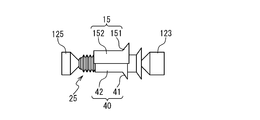
図15を参照して、シール塗布装置1は、スクレーパ15を備える。スクレーパ15は、ファスナー25のシール剤が塗布されるべき部位の形状に対応するように形成される。例えば、スクレーパ15は、スリーブ40の形状に沿った円錐部分付き円筒体を縦に2分割した形状に形成される。スクレーパ15は、皿部41に対応する部分円錐部151と、円筒部42に対応する部分円筒部152とを備える。
図16を参照して、部分円錐部151の内側面151aは、皿部41の形状に沿うように形成される。部分円筒部152の内側面152aは、円筒部42の形状に沿うように形成される。また、内側面152aには、互いに平行な複数の溝152bが形成されることが好ましい。例えば、複数の溝152bは、上記円錐部付き円筒体の円筒部分の内側面に形成された螺旋溝の部分である。スクレーパ15は、内側面151aが皿部41を向き且つ内側面152aが円筒部42を向いた状態で、内側面151aと皿部41の間及び内側面152aと円筒部42の間にそれぞれ隙間が形成されるように回転装置ベース121に取り付けられる。
本実施形態によれば、スリーブ40上のシール剤がスクレーパ15によって伸ばされる。したがって、シール剤の塗布膜を薄くすることができる。また、シールカートリッジ112内にエアが混入していた場合であっても、スリーブ40の表面にシール剤が塗布されない部分(塗り漏れ部分)が発生することが防がれる。更に、内側面152aの複数の溝152bは次の効果を奏する。複数の溝152bがなければスクレーパ15の外側にはみ出していたはずのシール剤が、複数の溝152bに充填されてファスナー25へ塗布されるため、少量のシール剤で多くのファスナー25を塗布できる。尚、内側面151aに溝を形成してもよい。
更に、スクレーパ15をゴムのような柔軟な材料で形成すれば、スクレーパ15とファスナー25との隙間を小さくしてシール剤の塗布膜を更に薄くすることができる。或いは、スクレーパ15のかわりに、波形のスクレーパ、ブラシ、又は、へらを用いてもよい。
(第3の実施形態)
本発明の第3の実施形態に係るシール塗布装置1及びシール塗布方法を説明する。第3の実施形態に係るシール塗布装置1及びシール塗布方法は、下記の説明を除いて第1又は第2の実施形態と同様である。
本発明の第3の実施形態に係るシール塗布装置1及びシール塗布方法を説明する。第3の実施形態に係るシール塗布装置1及びシール塗布方法は、下記の説明を除いて第1又は第2の実施形態と同様である。
図17を参照して、第3の実施形態に係るシール塗布装置1は、シール塗布状態確認装置16を備える。シール塗布状態確認装置16は、カメラ161と、画像処理装置162と、出力装置163と、記憶装置164とを備える。
図18を参照して、カメラ161は、ファスナー回転装置12にセットされた状態(把持部123及び125に把持された状態)のファスナー25を撮影して画像データを生成する。ここで、ファスナー回転装置12がファスナー25を回転させることで、互いに異なる複数の回転位置においてファスナー25を撮影することができる。したがって、ファスナー25の全周のシール剤の塗布状態を確認することができる。
画像処理装置162は、カメラ161が生成した画像データに対して画像処理を実行して、ファスナー25のシール剤が塗布された部分(塗布部分)とファスナー25のシール剤が塗布されていない部分(塗り漏れ部分)とを検出する。ここで、ファスナー25の皿ボルト20及びスリーブ40が金属製であり、シール剤が黒色であると、塗布部分(黒色部分)及び塗り漏れ部分(金属色部分)の検出が容易である。
出力装置163は、塗り漏れ部分が検出された場合にエラーを出力する。この場合、塗り漏れ部分に手作業でシール剤を塗布する。出力装置163は、画像処理前のファスナー25の画像や画像処理後のファスナー25の画像を出力してもよい。
記憶装置164は、画像処理前の画像データ、画像処理後の画像データ、及び、塗布部分及び塗り漏れ部分の検出結果をファスナー25の識別子と対応付けて記録する。これらは、品質管理等に利用される。
以上、実施形態を参照して本発明によるシール塗布装置及びシール塗布方法を説明したが、本発明は上記実施形態に限定されず、上記実施形態に様々な変更を加えたものも本発明に含まれる。
例えば、ファスナー25のねじ部23又は円筒部42に接触してファスナー中心軸S25がファスナー回転装置12の回転中心軸S12に一致するようにファスナー25の芯出しをする別の芯出し機構128を追加してもよい。
この出願は、2011年5月20日に出願された日本出願特願2011-113405号を基礎とする優先権を主張し、その開示の全てをここに取り込む。
Claims (14)
- シール剤が塗布されるべきファスナーを前記ファスナーの中心軸まわりに回転するファスナー回転装置を具備し、
前記ファスナー回転装置は、
前記ファスナーを軸方向に把持する第1把持部及び第2把持部と、
前記第1把持部及び前記第2把持部の少なくとも一方に対してトルクが伝達可能に接続されたモータと
を備える
シール塗布装置。 - 請求項1に記載のシール塗布装置であって、
前記ファスナー回転装置は、
前記第1把持部及び前記第2把持部が互いに近づくように前記第1把持部及び前記第2把持部の少なくとも一方を付勢する付勢部と、
前記ファスナーの前記中心軸が前記ファスナー回転装置の回転中心軸に一致するように前記ファスナーの芯出しをする芯出し機構と
を備える
シール塗布装置。 - 請求項1又は2に記載のシール塗布装置であって、
前記第1把持部及び前記第2把持部の少なくとも一方は、先端に向かって細くなるテーパー形状に形成される
シール塗布装置。 - 請求項1乃至3のいずれかに記載のシール塗布装置であって、
前記シール剤を吐出するシール剤吐出装置と、
前記ファスナー回転装置及び前記シール剤吐出装置を前記ファスナーの軸方向に相対的に移動するファスナー軸方向送り装置と
を更に具備する
シール塗布装置。 - 請求項1乃至4のいずれかに記載のシール塗布装置であって、
スクレーパを更に具備し、
前記スクレーパは、前記ファスナーの形状に沿うように形成された内側面を備え、
前記スクレーパは、前記内側面が前記ファスナーを向いた状態で前記内側面と前記ファスナーとの間に隙間が形成されるように配置される
シール塗布装置。 - 請求項5に記載のシール塗布装置であって、
前記内側面に互いに平行な複数の溝が形成された
シール塗布装置。 - 請求項1乃至6のいずれかに記載のシール塗布装置であって、
前記ファスナー回転装置にセットされた状態の前記ファスナーを撮影するカメラを更に具備する
シール塗布装置。 - 請求項7に記載のシール塗布装置であって、
前記カメラが前記ファスナーを撮影して生成した画像データに対して画像処理を実行して前記ファスナーの前記シール剤が塗布された部分と前記ファスナーの前記シール剤が塗布されていない部分とを検出する画像処理装置を更に具備する
シール塗布装置。 - ファスナーの軸方向に前記ファスナーを把持した状態で前記ファスナーの中心軸まわりに前記ファスナーを回転させながら、前記ファスナーにシール剤を塗布することを具備する
シール塗布方法。 - 請求項9に記載のシール塗布方法であって、
前記シール剤を塗布することにおいて、第1把持部及び第2把持部が前記ファスナーを前記軸方向に把持した状態で前記ファスナーを回転させ、
前記第1把持部及び前記第2把持部の少なくとも一方に対してモータがトルクの伝達が可能に接続され、
前記第1把持部及び前記第2把持部が前記ファスナーを把持した状態で前記ファスナーの前記中心軸が回転中心軸に一致するように前記ファスナーの芯出しをすることを更に具備し、
前記芯出しをすることにおいて、前記第1把持部及び前記第2把持部が互いに近づくように前記第1把持部及び前記第2把持部の少なくとも一方を付勢しながら前記ファスナーの芯出しを行う
シール塗布方法。 - 請求項9又は10に記載のシール塗布方法であって、
前記シール剤を塗布することは、
前記シール剤をノズルから吐出することと、
前記ノズル及び前記ファスナーを前記ファスナーの軸方向に相対的に移動することと
を備える
シール塗布方法。 - 請求項9乃至11のいずれかに記載のシール塗布方法であって、
前記シール剤を塗布することは、スクレーパを用いて前記シール剤を前記ファスナー上で伸ばすことを含む
シール塗布方法。 - 請求項9乃至12のいずれかに記載のシール塗布方法であって、
前記ファスナーを互いに異なる複数の回転位置において撮影することを更に具備する
シール塗布方法。 - 請求項13に記載のシール塗布方法であって、
前記ファスナーを互いに異なる複数の回転位置において撮影することにおいて、前記ファスナーの画像データを生成し、
前記画像データに対して画像処理を実行して前記ファスナーの前記シール剤が塗布された部分と前記ファスナーの前記シール剤が塗布されていない部分とを検出することを更に具備する
シール塗布方法。
Applications Claiming Priority (2)
| Application Number | Priority Date | Filing Date | Title |
|---|---|---|---|
| JP2011-113405 | 2011-05-20 | ||
| JP2011113405A JP2012239994A (ja) | 2011-05-20 | 2011-05-20 | シール塗布装置 |
Publications (1)
| Publication Number | Publication Date |
|---|---|
| WO2012161056A1 true WO2012161056A1 (ja) | 2012-11-29 |
Family
ID=47217136
Family Applications (1)
| Application Number | Title | Priority Date | Filing Date |
|---|---|---|---|
| PCT/JP2012/062557 Ceased WO2012161056A1 (ja) | 2011-05-20 | 2012-05-16 | シール塗布装置及びシール塗布方法 |
Country Status (2)
| Country | Link |
|---|---|
| JP (1) | JP2012239994A (ja) |
| WO (1) | WO2012161056A1 (ja) |
Cited By (4)
| Publication number | Priority date | Publication date | Assignee | Title |
|---|---|---|---|---|
| WO2014069393A1 (ja) * | 2012-10-30 | 2014-05-08 | 三菱重工業株式会社 | シール塗布装置及びシール塗布方法 |
| CN103785577A (zh) * | 2014-01-17 | 2014-05-14 | 上海宇田机电设备有限公司 | 一种瓶盖涂胶机构 |
| CN105643779A (zh) * | 2016-03-23 | 2016-06-08 | 叶侃 | 一种无杆气缸式卧式圆柱形陶瓷产品用夹持装置 |
| CN112354786A (zh) * | 2020-10-10 | 2021-02-12 | 南京飞赫电器有限公司 | 一种灯具用外壳涂胶设备及其工作方法 |
Families Citing this family (2)
| Publication number | Priority date | Publication date | Assignee | Title |
|---|---|---|---|---|
| JP6968771B2 (ja) | 2018-09-13 | 2021-11-17 | 三菱重工業株式会社 | 粘性体塗布装置 |
| CN110434022A (zh) * | 2019-09-06 | 2019-11-12 | 嵊州软岩智能技术有限公司 | 一种圆柱型工件表面打胶装置 |
Citations (6)
| Publication number | Priority date | Publication date | Assignee | Title |
|---|---|---|---|---|
| JPS57128375U (ja) * | 1981-02-03 | 1982-08-10 | ||
| JPS57191467U (ja) * | 1981-05-31 | 1982-12-04 | ||
| JPH0295470A (ja) * | 1988-09-30 | 1990-04-06 | Showa Electric Wire & Cable Co Ltd | ゴムローラ用コーティング装置 |
| JPH02502704A (ja) * | 1987-12-24 | 1990-08-30 | ナウチノ‐プロイズボドストベンノエ オビエディネニエポ ビプスク メハニチェスコゴ スバロチノゴ オボルドバニア (エヌペーオー“ベーイーエスペー”) | 回転体状製品上に高温ガス吹付けによる溶着被覆を施す装置 |
| JP2003024864A (ja) * | 2001-06-14 | 2003-01-28 | Nylok Fastener Corp | 締結具を被覆する処理制御器 |
| JP2003275655A (ja) * | 2002-03-25 | 2003-09-30 | Three Bond Co Ltd | 材料塗布装置 |
-
2011
- 2011-05-20 JP JP2011113405A patent/JP2012239994A/ja not_active Withdrawn
-
2012
- 2012-05-16 WO PCT/JP2012/062557 patent/WO2012161056A1/ja not_active Ceased
Patent Citations (6)
| Publication number | Priority date | Publication date | Assignee | Title |
|---|---|---|---|---|
| JPS57128375U (ja) * | 1981-02-03 | 1982-08-10 | ||
| JPS57191467U (ja) * | 1981-05-31 | 1982-12-04 | ||
| JPH02502704A (ja) * | 1987-12-24 | 1990-08-30 | ナウチノ‐プロイズボドストベンノエ オビエディネニエポ ビプスク メハニチェスコゴ スバロチノゴ オボルドバニア (エヌペーオー“ベーイーエスペー”) | 回転体状製品上に高温ガス吹付けによる溶着被覆を施す装置 |
| JPH0295470A (ja) * | 1988-09-30 | 1990-04-06 | Showa Electric Wire & Cable Co Ltd | ゴムローラ用コーティング装置 |
| JP2003024864A (ja) * | 2001-06-14 | 2003-01-28 | Nylok Fastener Corp | 締結具を被覆する処理制御器 |
| JP2003275655A (ja) * | 2002-03-25 | 2003-09-30 | Three Bond Co Ltd | 材料塗布装置 |
Cited By (6)
| Publication number | Priority date | Publication date | Assignee | Title |
|---|---|---|---|---|
| WO2014069393A1 (ja) * | 2012-10-30 | 2014-05-08 | 三菱重工業株式会社 | シール塗布装置及びシール塗布方法 |
| JP2014087739A (ja) * | 2012-10-30 | 2014-05-15 | Mitsubishi Heavy Ind Ltd | シール塗布装置及びシール塗布方法 |
| US9956582B2 (en) | 2012-10-30 | 2018-05-01 | Mitsubishi Heavy Industries, Ltd. | Sealant applying apparatus and sealant applying method |
| CN103785577A (zh) * | 2014-01-17 | 2014-05-14 | 上海宇田机电设备有限公司 | 一种瓶盖涂胶机构 |
| CN105643779A (zh) * | 2016-03-23 | 2016-06-08 | 叶侃 | 一种无杆气缸式卧式圆柱形陶瓷产品用夹持装置 |
| CN112354786A (zh) * | 2020-10-10 | 2021-02-12 | 南京飞赫电器有限公司 | 一种灯具用外壳涂胶设备及其工作方法 |
Also Published As
| Publication number | Publication date |
|---|---|
| JP2012239994A (ja) | 2012-12-10 |
Similar Documents
| Publication | Publication Date | Title |
|---|---|---|
| JP6095943B2 (ja) | シール塗布装置及びシール塗布方法 | |
| WO2012161056A1 (ja) | シール塗布装置及びシール塗布方法 | |
| WO2012161169A1 (ja) | シール塗布装置及びシール塗布方法 | |
| US11292077B2 (en) | Refill friction stir spot welding method and refill friction stir spot welding device | |
| US11344911B2 (en) | Sealant discharging nozzle and sealant discharging apparatus | |
| US5054980A (en) | Composite weldable stud and method of using same | |
| JP7489457B2 (ja) | 摩擦攪拌点接合装置及び継手構造 | |
| JP2014087739A5 (ja) | ||
| WO2019044437A1 (ja) | 粘性材料撹拌装置および粘性材料撹拌方法 | |
| JP5984639B2 (ja) | シール塗布装置及びシール塗布方法 | |
| US11426755B2 (en) | Sealant discharging nozzle and sealant discharging apparatus | |
| US11148188B2 (en) | Tool and associated method for installing a blind fastener | |
| US11325150B2 (en) | Sealant discharging nozzle and sealant discharging apparatus | |
| JP2021062409A5 (ja) | ||
| KR20220024723A (ko) | 패스너 전달 장치 | |
| KR20230046231A (ko) | 로봇 팔에 스프레이기를 부착하는 장치 | |
| CN211850672U (zh) | 末端出料执行机构及填缝机器人 | |
| JP2017226056A (ja) | チャック装置 | |
| US20250367801A1 (en) | Fastener driving tool including a nosepiece assembly and a nose positioner | |
| JP2006088207A (ja) | 溶接ロボット | |
| CN115256435B (zh) | 一种自适性物料夹取装置 | |
| JP2026019622A (ja) | 加工方法および加工システム | |
| CN119640259A (zh) | 一种激光熔覆送料装置 | |
| JP2008049293A (ja) | 紛体静電塗装装置 | |
| JP2017064828A (ja) | ワーク端面把持装置 |
Legal Events
| Date | Code | Title | Description |
|---|---|---|---|
| 121 | Ep: the epo has been informed by wipo that ep was designated in this application |
Ref document number: 12789338 Country of ref document: EP Kind code of ref document: A1 |
|
| NENP | Non-entry into the national phase |
Ref country code: DE |
|
| 122 | Ep: pct application non-entry in european phase |
Ref document number: 12789338 Country of ref document: EP Kind code of ref document: A1 |