WO2012160661A1 - Accumulateur et son procédé de fabrication - Google Patents
Accumulateur et son procédé de fabrication Download PDFInfo
- Publication number
- WO2012160661A1 WO2012160661A1 PCT/JP2011/061949 JP2011061949W WO2012160661A1 WO 2012160661 A1 WO2012160661 A1 WO 2012160661A1 JP 2011061949 W JP2011061949 W JP 2011061949W WO 2012160661 A1 WO2012160661 A1 WO 2012160661A1
- Authority
- WO
- WIPO (PCT)
- Prior art keywords
- unit cell
- battery
- case
- fluid
- electrode layer
- Prior art date
- Legal status (The legal status is an assumption and is not a legal conclusion. Google has not performed a legal analysis and makes no representation as to the accuracy of the status listed.)
- Ceased
Links
Images

Classifications
-
- H—ELECTRICITY
- H01—ELECTRIC ELEMENTS
- H01M—PROCESSES OR MEANS, e.g. BATTERIES, FOR THE DIRECT CONVERSION OF CHEMICAL ENERGY INTO ELECTRICAL ENERGY
- H01M50/00—Constructional details or processes of manufacture of the non-active parts of electrochemical cells other than fuel cells, e.g. hybrid cells
- H01M50/20—Mountings; Secondary casings or frames; Racks, modules or packs; Suspension devices; Shock absorbers; Transport or carrying devices; Holders
- H01M50/258—Modular batteries; Casings provided with means for assembling
-
- H—ELECTRICITY
- H01—ELECTRIC ELEMENTS
- H01M—PROCESSES OR MEANS, e.g. BATTERIES, FOR THE DIRECT CONVERSION OF CHEMICAL ENERGY INTO ELECTRICAL ENERGY
- H01M10/00—Secondary cells; Manufacture thereof
- H01M10/04—Construction or manufacture in general
- H01M10/0481—Compression means other than compression means for stacks of electrodes and separators
-
- H—ELECTRICITY
- H01—ELECTRIC ELEMENTS
- H01M—PROCESSES OR MEANS, e.g. BATTERIES, FOR THE DIRECT CONVERSION OF CHEMICAL ENERGY INTO ELECTRICAL ENERGY
- H01M50/00—Constructional details or processes of manufacture of the non-active parts of electrochemical cells other than fuel cells, e.g. hybrid cells
- H01M50/20—Mountings; Secondary casings or frames; Racks, modules or packs; Suspension devices; Shock absorbers; Transport or carrying devices; Holders
- H01M50/202—Casings or frames around the primary casing of a single cell or a single battery
-
- H—ELECTRICITY
- H01—ELECTRIC ELEMENTS
- H01M—PROCESSES OR MEANS, e.g. BATTERIES, FOR THE DIRECT CONVERSION OF CHEMICAL ENERGY INTO ELECTRICAL ENERGY
- H01M10/00—Secondary cells; Manufacture thereof
- H01M10/05—Accumulators with non-aqueous electrolyte
- H01M10/052—Li-accumulators
-
- H—ELECTRICITY
- H01—ELECTRIC ELEMENTS
- H01M—PROCESSES OR MEANS, e.g. BATTERIES, FOR THE DIRECT CONVERSION OF CHEMICAL ENERGY INTO ELECTRICAL ENERGY
- H01M2220/00—Batteries for particular applications
- H01M2220/20—Batteries in motive systems, e.g. vehicle, ship, plane
-
- H—ELECTRICITY
- H01—ELECTRIC ELEMENTS
- H01M—PROCESSES OR MEANS, e.g. BATTERIES, FOR THE DIRECT CONVERSION OF CHEMICAL ENERGY INTO ELECTRICAL ENERGY
- H01M50/00—Constructional details or processes of manufacture of the non-active parts of electrochemical cells other than fuel cells, e.g. hybrid cells
- H01M50/10—Primary casings; Jackets or wrappings
- H01M50/102—Primary casings; Jackets or wrappings characterised by their shape or physical structure
- H01M50/103—Primary casings; Jackets or wrappings characterised by their shape or physical structure prismatic or rectangular
-
- H—ELECTRICITY
- H01—ELECTRIC ELEMENTS
- H01M—PROCESSES OR MEANS, e.g. BATTERIES, FOR THE DIRECT CONVERSION OF CHEMICAL ENERGY INTO ELECTRICAL ENERGY
- H01M50/00—Constructional details or processes of manufacture of the non-active parts of electrochemical cells other than fuel cells, e.g. hybrid cells
- H01M50/10—Primary casings; Jackets or wrappings
- H01M50/14—Primary casings; Jackets or wrappings for protecting against damage caused by external factors
-
- H—ELECTRICITY
- H01—ELECTRIC ELEMENTS
- H01M—PROCESSES OR MEANS, e.g. BATTERIES, FOR THE DIRECT CONVERSION OF CHEMICAL ENERGY INTO ELECTRICAL ENERGY
- H01M50/00—Constructional details or processes of manufacture of the non-active parts of electrochemical cells other than fuel cells, e.g. hybrid cells
- H01M50/10—Primary casings; Jackets or wrappings
- H01M50/183—Sealing members
- H01M50/186—Sealing members characterised by the disposition of the sealing members
-
- H—ELECTRICITY
- H01—ELECTRIC ELEMENTS
- H01M—PROCESSES OR MEANS, e.g. BATTERIES, FOR THE DIRECT CONVERSION OF CHEMICAL ENERGY INTO ELECTRICAL ENERGY
- H01M50/00—Constructional details or processes of manufacture of the non-active parts of electrochemical cells other than fuel cells, e.g. hybrid cells
- H01M50/20—Mountings; Secondary casings or frames; Racks, modules or packs; Suspension devices; Shock absorbers; Transport or carrying devices; Holders
- H01M50/218—Mountings; Secondary casings or frames; Racks, modules or packs; Suspension devices; Shock absorbers; Transport or carrying devices; Holders characterised by the material
- H01M50/22—Mountings; Secondary casings or frames; Racks, modules or packs; Suspension devices; Shock absorbers; Transport or carrying devices; Holders characterised by the material of the casings or racks
- H01M50/222—Inorganic material
- H01M50/224—Metals
-
- Y—GENERAL TAGGING OF NEW TECHNOLOGICAL DEVELOPMENTS; GENERAL TAGGING OF CROSS-SECTIONAL TECHNOLOGIES SPANNING OVER SEVERAL SECTIONS OF THE IPC; TECHNICAL SUBJECTS COVERED BY FORMER USPC CROSS-REFERENCE ART COLLECTIONS [XRACs] AND DIGESTS
- Y02—TECHNOLOGIES OR APPLICATIONS FOR MITIGATION OR ADAPTATION AGAINST CLIMATE CHANGE
- Y02E—REDUCTION OF GREENHOUSE GAS [GHG] EMISSIONS, RELATED TO ENERGY GENERATION, TRANSMISSION OR DISTRIBUTION
- Y02E60/00—Enabling technologies; Technologies with a potential or indirect contribution to GHG emissions mitigation
- Y02E60/10—Energy storage using batteries
-
- Y—GENERAL TAGGING OF NEW TECHNOLOGICAL DEVELOPMENTS; GENERAL TAGGING OF CROSS-SECTIONAL TECHNOLOGIES SPANNING OVER SEVERAL SECTIONS OF THE IPC; TECHNICAL SUBJECTS COVERED BY FORMER USPC CROSS-REFERENCE ART COLLECTIONS [XRACs] AND DIGESTS
- Y02—TECHNOLOGIES OR APPLICATIONS FOR MITIGATION OR ADAPTATION AGAINST CLIMATE CHANGE
- Y02P—CLIMATE CHANGE MITIGATION TECHNOLOGIES IN THE PRODUCTION OR PROCESSING OF GOODS
- Y02P70/00—Climate change mitigation technologies in the production process for final industrial or consumer products
- Y02P70/50—Manufacturing or production processes characterised by the final manufactured product
-
- Y—GENERAL TAGGING OF NEW TECHNOLOGICAL DEVELOPMENTS; GENERAL TAGGING OF CROSS-SECTIONAL TECHNOLOGIES SPANNING OVER SEVERAL SECTIONS OF THE IPC; TECHNICAL SUBJECTS COVERED BY FORMER USPC CROSS-REFERENCE ART COLLECTIONS [XRACs] AND DIGESTS
- Y10—TECHNICAL SUBJECTS COVERED BY FORMER USPC
- Y10T—TECHNICAL SUBJECTS COVERED BY FORMER US CLASSIFICATION
- Y10T29/00—Metal working
- Y10T29/49—Method of mechanical manufacture
- Y10T29/49002—Electrical device making
- Y10T29/49108—Electric battery cell making
- Y10T29/4911—Electric battery cell making including sealing
Definitions
- the present invention relates to a battery and a manufacturing method thereof, and more particularly to a battery that pressurizes a unit cell using a fluid and a manufacturing method thereof.
- a lithium ion secondary battery (hereinafter sometimes referred to as a “lithium secondary battery”) has characteristics that it has a higher energy density than other secondary batteries and can operate at a high voltage. For this reason, it is used as a secondary battery that can be easily reduced in size and weight in information equipment such as a mobile phone, and in recent years, there is an increasing demand for large motive power such as for electric vehicles and hybrid vehicles.
- a lithium ion secondary battery includes a positive electrode layer and a negative electrode layer, and an electrolyte layer disposed therebetween.
- the electrolyte used for the electrolyte layer include non-aqueous liquid and solid substances. Are known.
- electrolytic solution a liquid electrolyte (hereinafter referred to as “electrolytic solution”)
- the electrolytic solution easily penetrates into the positive electrode layer and the negative electrode layer. Therefore, an interface between the active material contained in the positive electrode layer or the negative electrode layer and the electrolytic solution is easily formed, and the performance is easily improved.
- the widely used electrolyte is flammable, it is necessary to mount a system for ensuring safety.
- solid electrolyte a solid electrolyte that is nonflammable
- solid electrolyte layer a layer containing a solid electrolyte that is nonflammable
- Patent Document 1 discloses an assembled battery in which a plurality of unit cells are combined and accommodated in an assembled battery case. Or the lithium secondary battery which pressurizes a unit cell using the hydrostatic pressure which arises in an assembled battery case by being filled with at least 1 sort (s) of solid powder, or these mixed substances is disclosed.
- the unit cell is pressurized using the hydrostatic pressure generated in the assembled battery case. Therefore, it is considered that the unit cell can be easily pressurized uniformly.
- the technique disclosed in Patent Document 1 there is a problem that it is difficult to pressurize the unit cell uniformly if a large amount of gas remains in the unit cell case.
- an object of the present invention is to provide a battery that can uniformly pressurize the unit cell and a method for manufacturing the battery.
- a first aspect of the present invention includes a laminate having a positive electrode layer, a negative electrode layer, and an electrolyte layer disposed between the positive electrode layer and the negative electrode layer, and a unit cell case containing the laminate.
- a unit cell and an outer battery case that accommodates the unit cell, and a fluid that can pressurize the unit cell is filled inside and outside the unit cell case, and the unit cell case is sealed.
- the battery is characterized in that the stop is located outside the outer battery case.
- a second aspect of the present invention includes a laminate having a positive electrode layer, a negative electrode layer, and an electrolyte layer disposed between the positive electrode layer and the negative electrode layer, and a unit cell case containing the laminate.
- a battery comprising: a unit cell; and an outer battery case that accommodates the unit cell, wherein the unit cell manufacturing step for manufacturing the unit cell, and after the unit cell manufacturing step, While the sealing port is arranged outside the outer battery case, the housing step for housing the unit cell in the outer battery case, and after the housing step, the sealing port of the unit cell case is opened.
- the fluid is injected until the fluid pressure becomes the first pressure in the injection step.
- the pressure of the fluid to pressurize the unit cell is changed to the first pressure. It is preferable to have a decompression step that reduces the pressure rather than the pressure.
- the sealing opening of the unit cell case is outside the outer battery case. Therefore, when the fluid to pressurize the unit cell is sealed outside the unit cell case and inside the outer cell case, the gas remaining in the unit cell case is moved out of the unit cell case and outside the unit cell case. As a result, the gas remaining in the unit cell case can be reduced. By reducing the gas remaining in the unit cell case, it is possible to uniformly pressurize the unit cell using the fluid filled outside the unit cell case. Therefore, according to the 1st aspect of this invention, the battery which can pressurize a unit cell uniformly can be provided.
- the second aspect of the present invention has an injection step of injecting a fluid to pressurize the unit cell in a state where the sealing port of the unit cell case arranged outside the exterior battery case is opened.
- a pressure reducing step for reducing the pressure of the fluid injected in the injecting step is provided, thereby ensuring the fluid pressure necessary for pressurizing the unit cell. It is possible to avoid a situation in which excessive pressure is applied to the unit cell case and the outer battery case. By avoiding the situation where excessive pressure is applied, it becomes easier to suppress the damage of the unit cell case and the outer battery case, and by preventing the unit cell case and the outer battery case from being damaged, It becomes easy to pressurize the battery uniformly. Therefore, it becomes easy to pressurize a unit cell uniformly over a long period of time by setting it as the form which has a pressure reduction process in addition to the said effect.
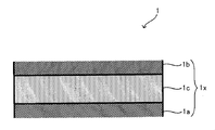
- FIG. 2 is a cross-sectional view illustrating a laminated body 1.
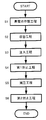
- FIG. It is a flowchart explaining the manufacturing method of the battery of this invention. It is sectional drawing explaining an injection
- FIG. 5 is a diagram for explaining a conventional battery manufacturing method.
- a laminate 1 having a positive electrode layer, a solid electrolyte layer, and a negative electrode layer is conventionally used as a laminate film 2.
- S91 the inside of the laminate film 2 is depressurized and the outlet 96x of the gas discharge path 96 is sealed with the sealing material 7 (S92), and then the laminate film 2 is placed in the exterior battery case 94 (S93). After injecting the fluid 5 into the case 94, the inlet 8x of the fluid injection path 8 was sealed with the sealing material 9 (S94).
- the present inventor has arranged the outlet of the gas discharge passage through which the gas discharged from the inside of the laminated film 2 flows outside to the outside of the outer battery case 4, so that the laminated film It has been found that it is possible to simultaneously perform decompression in 2 and injection of the fluid 5 into the outer battery case 4.
- decompressing the laminate film 2 and injecting the fluid 5 at the same time first, an amount of fluid exceeding the pressure required for pressurizing the battery is injected into the exterior of the laminate film 2 and into the exterior battery case 4.
- the inlet of the fluid is closed, so that the volume energy density and weight are reduced. It has been found that the laminated body 1 accommodated in the laminate film 2 can be uniformly pressed while improving the energy density.
- the present invention has been made based on such knowledge.
- the battery of the present invention is a lithium ion secondary battery (solid battery) using a solid electrolyte layer
- the form shown below is an illustration of this invention and this invention is not limited to the form shown below.
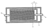
- FIG. 1 is a cross-sectional view for explaining a battery 10 of the present invention
- FIG. 2 is a cross-sectional view for explaining a laminate 1 provided in the battery 10.
- a part of the laminate 1 is shown in an enlarged manner.
- the battery 10 includes a stacked body 1 and a unit cell 3 including a unit cell case 2 that houses the stacked body, and an exterior battery case 4 that houses the unit cell 3.
- the fluid 5 is filled in the outside of the unit cell case 2 and the inside of the exterior battery case 4.
- the unit cell case 2 is connected to a gas discharge path 6 used when the gas in the unit cell case 2 is discharged to the outside, and one end of the gas discharge path 6 which is a sealing port of the unit cell case 2 is connected to the unit cell case 2.
- the outer battery case 4 is located outside.
- One end of the gas discharge path 6 located outside the outer battery case 4 (hereinafter referred to as “the outlet of the gas discharge path 6”) is sealed with a sealing material 7.
- the outer battery case 4 is connected to a fluid injection path 8 used when the fluid 5 is injected into the outer side of the unit cell case 2 and the inner side of the outer battery case 4, and is positioned outside the outer battery case 4.
- One end of the fluid injection path 8 (hereinafter referred to as “inlet of the fluid injection path 8”) is sealed with a sealing material 9.
- the laminate 1 includes an electrode body 1x having a positive electrode layer 1a, a negative electrode layer 1b, and a solid electrolyte layer 1c sandwiched between the positive electrode layer 1a and the negative electrode layer 1b.
- the positive electrode layer 1a is connected to a positive electrode terminal (not shown) via a positive electrode current collector (not shown), and the negative electrode layer 1b is connected to a negative electrode terminal (not shown) via a negative electrode current collector (not shown).
- One end of each of the negative electrode terminal and the negative electrode terminal is located outside the outer battery case 4.
- the laminated body 1 includes one or two or more electrode bodies 1x. When the laminated body 1 includes two or more electrode bodies 1x, 1x,..., The adjacent electrode bodies 1x, 1x are electrically Connected in series or in parallel.
- the battery 10 configured in this way can be manufactured through the following steps, for example.
- the laminated body 1 is first produced through the process of arrange
- the unit cell 3 is connected to the outer battery to which the fluid injection path 8 is connected. Housed in case 4.
- the fluid 5 is filled outside the laminate film 2 and inside the outer battery case 4 with the outlet of the gas discharge path 6 opened.
- the laminate film 2 can be pressurized with the fluid 5, and the gas remaining in the laminate film 2 is removed from the outlet of the gas discharge path 6.
- the battery 10 can be manufactured through the above steps.
- the laminate 1 may have a sheet-like form formed by laminating a sheet-like positive electrode layer 1a, a solid electrolyte layer 1c, and a negative electrode layer 1b.
- stacking the solid electrolyte layer 1c and the negative electrode layer 1b in the cylinder shape may be sufficient.
- the outlet of the gas discharge path 6 when the fluid 5 is injected into the outer side of the laminate film 2 and the inner side of the outer battery case 4, By opening the outlet, the laminate film 2 can be easily pressurized using the fluid 5.
- the gas remaining in the laminate film 2 can be discharged to the outside of the outer battery case 4. That is, the decompression in the laminate film 2 and the injection of the fluid 5 can be performed simultaneously.
- the gas etc. which exist outside the exterior battery case 4 flow into the inside of the laminate film 2 by sealing the outlet of the gas discharge path 6.
- the unit cell 3 can be uniformly pressurized by the fluid 5 filled outside the laminate film 2 and inside the outer battery case 4. Therefore, according to this invention, the battery 10 which can pressurize the unit cell 3 uniformly can be provided.
- the positive electrode active material to be contained in the positive electrode layer 1a a known positive electrode active material that can be contained in the positive electrode layer of the lithium ion secondary battery can be appropriately used.
- a positive electrode active material a layered compound such as lithium cobaltate (LiCoO 2 ) can be exemplified.
- the well-known solid electrolyte which can be contained in the positive electrode layer of a lithium ion secondary battery can be suitably contained in the positive electrode layer 1a.
- Examples thereof include a sulfide solid electrolyte produced in the above manner.
- the positive electrode layer 1a may contain a binder that binds the positive electrode active material and the solid electrolyte and a conductive material that improves conductivity.
- Examples of the binder that can be contained in the positive electrode layer 1a include butylene rubber, and examples of the conductive material that can be contained in the positive electrode layer 1a include carbon black.
- the known solvent which can be used when preparing the slurry used at the time of preparation of the positive electrode layer of a lithium ion secondary battery can be used suitably at the time of preparation of the positive electrode layer 1a. As such a solvent, heptane and the like can be exemplified.
- the negative electrode active material contained in the negative electrode layer 1b a known negative electrode active material that can be contained in the negative electrode layer of the lithium ion secondary battery can be appropriately used.
- a negative electrode active material include graphite.
- the negative electrode layer 1b can contain a solid electrolyte, and can appropriately contain a known solid electrolyte that can be contained in the negative electrode layer of the lithium ion secondary battery. Examples of such a solid electrolyte include the solid electrolyte that can be contained in the positive electrode layer 1a.
- the negative electrode layer 1b may contain a binder that binds the negative electrode active material and the solid electrolyte or a conductive material that improves conductivity.
- binder and conductive material that can be contained in the negative electrode layer 1b examples include the binder and conductive material that can be contained in the positive electrode layer 1a.
- said solvent etc. which can be used at the time of preparation of the positive electrode layer 1a can be used suitably at the time of preparation of the negative electrode layer 1b.
- examples of the solid electrolyte contained in the solid electrolyte layer 1c include the solid electrolytes that can be contained in the positive electrode layer 1a.
- the said solvent etc. which can be used at the time of preparation of the positive electrode layer 1a can be used suitably at the time of preparation of the solid electrolyte layer 1c.
- the positive electrode current collector and the negative electrode current collector, as well as the positive electrode terminal and the negative electrode terminal are known positive electrodes and negative electrode current collectors that can be used as the positive electrode terminal and the negative electrode terminal of the lithium ion secondary battery.
- It can be made of a conductive material.
- a conductive material include one or more elements selected from the group consisting of Cu, Ni, Al, V, Au, Pt, Mg, Fe, Ti, Co, Cr, Zn, Ge, and In. Examples of the metal material to be included can be given.
- the unit cell case 2 (laminate film 2) is a film that can withstand the environment during use of the lithium ion secondary battery, has a property of not allowing gas and liquid to permeate, and can be sealed. It can use without being specifically limited.
- the constituent material of such a film include resin films such as polyethylene, polyvinyl fluoride, and polyvinylidene chloride, and metal deposited films obtained by depositing a metal such as aluminum on these surfaces.
- the outer battery case 4 is not particularly limited as long as the outer battery case 4 is made of a material that can withstand the environment during operation of the battery 10 and the pressure of the fluid 5.
- the exterior battery case 4 can be made of metal such as aluminum or stainless steel, for example.
- the fluid 5 in addition to an incombustible gas typified by carbon dioxide or the like, an inert gas typified by helium, nitrogen, argon or the like can be used. In addition, dry air can be used as the fluid 5. However, it is preferable to use the nonflammable gas or the inert gas from the viewpoint of making the battery easy to improve the safety.
- the pressure of the fluid 5 that pressurizes the unit cell 3 can be, for example, about 1 to 200 atm.
- the material of the gas discharge path 6 and the fluid injection path 8 is not particularly limited as long as the gas discharge path 6 and the fluid injection path 8 are made of a material that can withstand the pressure of the fluid 5.
- a known pipe formed of a resin reinforced by embedding a braided metal wire can be appropriately used.
- sealing material 7 a known substance capable of closing the outlet of the gas discharge path 6 is appropriately used so that gas existing outside the outer battery case 4 does not flow into the laminate film 2. It can.
- a known substance include known metal foils represented by aluminum foil and the like, thermosetting resins such as epoxy resins, and the like.
- the sealing material 9 is made of a known substance that can block the inlet of the fluid injection path 8 so that the fluid 5 filled inside the outer battery case 4 does not leak outside the outer battery case 4. It can be used as appropriate.
- a known substance include known metal foils represented by aluminum foil and the like, thermosetting resins such as epoxy resins, and the like.
- gas is exemplified as the fluid 5, but the fluid 5 in the present invention is not limited to gas.
- the fluid 5 may be a known liquid, and a solid may be used together with a gas or a liquid.
- FIG. 3 is a flow diagram for explaining a method for producing a battery of the present invention
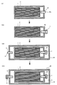
- FIG. 4 is a cross-sectional view for explaining an injection process.
- the case where the battery 10 is manufactured by the battery manufacturing method of the present invention will be described with reference to FIGS. 1 to 4.
- the battery manufacturing method of the present invention includes a unit cell manufacturing step (S1), a housing step (S2), an injection step (S3), a first sealing step (S4), It has a decompression step (S5) and a second sealing step (S6).
- the battery 10 can be manufactured through these steps.
- the unit cell manufacturing step (hereinafter referred to as “S1”) is a step of manufacturing the unit cell 3.
- S1 can be divided roughly into the process of producing the laminated body 1, and the process of accommodating the laminated body 1 in the laminate film 2 to which the gas exhaust path 6 was connected.
- the laminate 1 for example, through a process of applying a positive electrode composition prepared by dispersing at least a positive electrode active material and a solid electrolyte in a solvent to the surface of the positive electrode current collector,
- the positive electrode layer 1a is formed on the surface.
- the negative electrode layer 1b is formed on the surface of a negative electrode collector through the process of apply
- the solid electrolyte layer 1c is the positive electrode layer 1a and the negative electrode layer 1b.
- the negative electrode layer 1b formed on the surface of the negative electrode current collector is disposed on the solid electrolyte layer 1c formed on the surface of the positive electrode layer 1a so as to be sandwiched between the layers.
- the laminated body 1 is a cylindrical form, for example, after giving compressive force from the both ends in the thickness direction, the cylindrical body is wound into a cylindrical body, and then the end faces of the cylindrical body are Through the process of joining, the laminated body 1 having a cylindrical shape can be produced.
- the gas discharge path 6 is formed while not accommodating all of the end of the negative electrode current collector connected to the negative electrode terminal and the end of the positive electrode current collector connected to the positive electrode terminal.
- the laminate 1 is wrapped with a laminate film 2 to which are connected.
- the gas discharge path 6 can be joined to the laminate film 2 using a known adhesive or the like.
- the laminate 1 and the laminate 1 are subjected to a process such as heating and heat-sealing the laminate film 2 (outer edge of the laminate film 2) positioned around the laminate 1.
- a unit cell 3 having a laminate film 2 wrapping the laminate 1 can be produced.
- the housing step (hereinafter referred to as “S2”) is made in S1 while the outlet 6x of the gas discharge path 6 corresponding to the sealing port of the unit cell case 2 is disposed outside the outer battery case 4.
- the unit cell 3 is housed in the outer battery case 4.
- S2 is a process shown below. be able to. First, the positive electrode terminal and the positive electrode current collector whose end are located on the outside of the casing are connected, and the negative electrode terminal and the negative electrode current collector whose end are located on the outer side of the casing are connected.
- the unit cell 3 is accommodated in the casing through the opening of the casing. Thereafter, the gas exhaust path 6 is passed through a hole for the gas exhaust path 6 provided in the lid so that the outlet 6x of the gas exhaust path 6 is disposed outside the outer battery case 4, and the opening of the housing is opened. Close with a lid. After the opening of the housing is closed with the lid in this way, the housing and the lid are joined to each other, the positive terminal hole and the negative terminal hole provided in the housing, and the gas exhaust provided in the lid The hole for the road 6 is closed.
- the unit cell 3 can be accommodated in the exterior battery case 4 by S2 of such a form.
- FIG. 4 shows a cross section of the unit cell 3, the outer battery case 4, the gas discharge path 6, and the fluid injection path 8 when S3 is performed. As shown in FIG. 4, S3 is performed in a state where the outlet 6x of the gas discharge path 6 is opened.
- the amount of gas discharged from the outlet 6x of the gas discharge path 6 can be adjusted by adjusting the pressure of the fluid 5 injected in S3. More specifically, the amount of gas discharged from the outlet 6x of the gas discharge path 6 is increased by increasing the pressure of the fluid 5 injected in S3, that is, the amount of gas remaining in the laminate film 2. Can be reduced.
- the first sealing step (hereinafter sometimes referred to as “S4”) is a step of sealing the outlet 6x of the gas discharge path 6 with the sealing material 7 after the start of S3.
- the method for sealing the outlet 6x of the gas discharge path 6 is not particularly limited, and a known method can be used.
- the decompression step (hereinafter sometimes referred to as “S5”) is a step of reducing the pressure of the fluid 5 injected into the outside of the laminate film 2 and the inside of the exterior battery case 4 after the above S4.
- the amount of gas present in the laminate film 2 can be reduced by increasing the pressure of the fluid 5 injected into the outer battery case 4 in S3.
- the pressure of the fluid 5 injected in S3 can be maintained as it is.
- the laminate film 2 and the exterior battery case 4 are It is necessary to have pressure resistance that can withstand pressure. In order to increase the pressure resistance of the laminate film 2 and the outer battery case 4, it is necessary to take measures such as increasing the thickness thereof.
- the volume energy density and weight energy density of the battery are reduced.
- Cheap In order to obtain a battery having an increased volume energy density or weight energy density, it is effective to reduce the thickness of the laminate film 2 or the outer battery case 4. However, it is effective to reduce the pressure of the fluid 5 injected in S ⁇ b> 3 after S ⁇ b> 4 in order to make the unit cell 3 capable of being uniformly pressurized over a long period of time. From this viewpoint, in the battery manufacturing method of the present invention shown in FIG. 3, S5 is performed after S4.
- the second sealing step (hereinafter sometimes referred to as “S6”) is a step of sealing the inlet 8x of the fluid injection path 8 with the sealing material 9 after S5.
- the method for sealing the inlet 8x of the fluid injection path 8 is not particularly limited, and a known method can be used. By sealing the inlet 8x of the fluid injection path 8, it is possible to maintain a state where the unit cell 3 is uniformly pressurized by the fluid 5.
- the battery 10 capable of uniformly pressing the unit cell 3 can be manufactured. Therefore, according to this invention, the manufacturing method of a battery which can manufacture the battery which can pressurize a unit cell uniformly can be provided.
- the method for manufacturing a battery of the present invention a mode having a pressure reducing step after S3 (more specifically, after S4) has been exemplified, but the method for manufacturing a battery of the present invention is limited to this mode.
- the pressure reducing process is performed after the injection process (for example, after the first sealing process). It is preferable to have a form having
- the manufacturing method of the battery of this invention is not limited to the said form.
- a first sealing step for sealing the sealing port of the unit cell case after the start of the injection step, and a second sealing step for sealing the assembled battery case after the first sealing step is preferable.
- the battery of the present invention may be configured such that ions other than lithium ions move between the positive electrode layer and the negative electrode layer, and the method for manufacturing a battery of the present invention moves ions other than lithium ions. It is also possible to use a method for manufacturing a battery. Examples of such ions include sodium ions, potassium ions, magnesium ions, calcium ions, and the like. In the case where ions other than lithium ions move, the positive electrode active material, the solid electrolyte, and the negative electrode active material may be appropriately selected according to the moving ions.
- the battery of the present invention may be a battery having an electrolyte layer using an electrolytic solution
- the battery manufacturing method of the present invention may be a method of manufacturing a battery having an electrolyte layer using an electrolytic solution. It is.
- the battery of the present invention may be a so-called primary battery, and the battery manufacturing method of the present invention may be a method of manufacturing a primary battery.
Landscapes
- Chemical & Material Sciences (AREA)
- Chemical Kinetics & Catalysis (AREA)
- Electrochemistry (AREA)
- General Chemical & Material Sciences (AREA)
- Engineering & Computer Science (AREA)
- Manufacturing & Machinery (AREA)
- Secondary Cells (AREA)
- Gas Exhaust Devices For Batteries (AREA)
- Battery Mounting, Suspending (AREA)
- Primary Cells (AREA)
Abstract
Priority Applications (4)
| Application Number | Priority Date | Filing Date | Title |
|---|---|---|---|
| CN201180003881.7A CN102906898B (zh) | 2011-05-25 | 2011-05-25 | 电池及其制造方法 |
| US13/395,507 US20140162115A1 (en) | 2011-05-25 | 2011-05-25 | Battery and method for manufacturing the same |
| PCT/JP2011/061949 WO2012160661A1 (fr) | 2011-05-25 | 2011-05-25 | Accumulateur et son procédé de fabrication |
| JP2011542610A JP5382134B2 (ja) | 2011-05-25 | 2011-05-25 | 電池及びその製造方法 |
Applications Claiming Priority (1)
| Application Number | Priority Date | Filing Date | Title |
|---|---|---|---|
| PCT/JP2011/061949 WO2012160661A1 (fr) | 2011-05-25 | 2011-05-25 | Accumulateur et son procédé de fabrication |
Publications (1)
| Publication Number | Publication Date |
|---|---|
| WO2012160661A1 true WO2012160661A1 (fr) | 2012-11-29 |
Family
ID=47216764
Family Applications (1)
| Application Number | Title | Priority Date | Filing Date |
|---|---|---|---|
| PCT/JP2011/061949 Ceased WO2012160661A1 (fr) | 2011-05-25 | 2011-05-25 | Accumulateur et son procédé de fabrication |
Country Status (4)
| Country | Link |
|---|---|
| US (1) | US20140162115A1 (fr) |
| JP (1) | JP5382134B2 (fr) |
| CN (1) | CN102906898B (fr) |
| WO (1) | WO2012160661A1 (fr) |
Cited By (5)
| Publication number | Priority date | Publication date | Assignee | Title |
|---|---|---|---|---|
| JP2022513762A (ja) * | 2018-12-11 | 2022-02-09 | テラワット テクノロジー インコーポレイテッド | 固体電池のための油圧式等方圧プレスプロセス |
| JP2022067369A (ja) * | 2020-10-20 | 2022-05-06 | プライムプラネットエナジー&ソリューションズ株式会社 | 非水電解液二次電池用電池ケースおよびその利用 |
| JP2023510555A (ja) * | 2020-01-13 | 2023-03-14 | ビーワイディー カンパニー リミテッド | 電池、電池モジュール、電池パック及び電気自動車 |
| JP2023102760A (ja) * | 2022-01-12 | 2023-07-25 | ハナ テクノロジー カンパニー リミテッド | 全固体用二次電池高温加圧システム及び方法 |
| JP2025067065A (ja) * | 2023-10-12 | 2025-04-24 | トヨタ自動車株式会社 | ラミネート電池 |
Families Citing this family (4)
| Publication number | Priority date | Publication date | Assignee | Title |
|---|---|---|---|---|
| CA3109523A1 (fr) * | 2018-08-30 | 2020-03-05 | Hydro-Quebec | Batterie rechargeable avec electrolyte liquide ionique et pression d'electrode |
| CN110828745B (zh) * | 2020-01-13 | 2020-07-10 | 比亚迪股份有限公司 | 一种电池、电池模组、电池包和电动车 |
| EP4213259A1 (fr) * | 2022-01-12 | 2023-07-19 | Hana Technology Co., Ltd. | Système et procédé de mise sous pression à haute température d'une batterie secondaire entièrement solide |
| KR20230125553A (ko) * | 2022-02-21 | 2023-08-29 | 주식회사 엘지에너지솔루션 | 전지 셀 가압 장치 및 이를 포함하는 전지 셀 충방전 장치 |
Citations (3)
| Publication number | Priority date | Publication date | Assignee | Title |
|---|---|---|---|---|
| JPH07220753A (ja) * | 1994-01-31 | 1995-08-18 | Sony Corp | 組電池構造体 |
| JPH10214638A (ja) * | 1997-01-30 | 1998-08-11 | Hitachi Ltd | リチウム二次電池 |
| JP2008147010A (ja) * | 2006-12-08 | 2008-06-26 | Nissan Motor Co Ltd | 電力供給装置およびその制御方法 |
Family Cites Families (13)
| Publication number | Priority date | Publication date | Assignee | Title |
|---|---|---|---|---|
| DE19837909C2 (de) * | 1998-08-20 | 2001-05-17 | Implex Hear Tech Ag | Schutzvorrichtung für eine mehrfach nachladbare elektrochemische Batterie |
| JP3791841B2 (ja) * | 2002-08-29 | 2006-06-28 | 三菱化学株式会社 | 形状可変性包装体の漏れ検査方法、それを用いた電池の検査方法および電池の製造方法 |
| KR100560158B1 (ko) * | 2003-09-29 | 2006-03-16 | 주식회사 코캄 | 고 안전성 리튬 이차 전지 및 그 제조방법 |
| WO2008099602A1 (fr) * | 2007-02-16 | 2008-08-21 | Panasonic Corporation | Unité de stockage en énergie électrique |
| CN101222071A (zh) * | 2007-03-22 | 2008-07-16 | 胡远明 | 钠硫蓄电池 |
| US7967025B2 (en) * | 2007-08-03 | 2011-06-28 | Scg (Thailand) Co., Ltd. | Overfill protection device (OPD) |
| JP2010108788A (ja) * | 2008-10-30 | 2010-05-13 | Sanyo Electric Co Ltd | バッテリシステム |
| JP5509684B2 (ja) * | 2009-06-03 | 2014-06-04 | ソニー株式会社 | 電池パック |
| CN101710629B (zh) * | 2009-11-03 | 2012-05-30 | 赛恩斯能源科技有限公司 | 电池组充电方法 |
| JP5649811B2 (ja) * | 2009-11-09 | 2015-01-07 | 三洋電機株式会社 | 車両用電源装置及びこれを備える車両並びに車両用電源装置の製造方法 |
| JP5257471B2 (ja) * | 2010-12-28 | 2013-08-07 | トヨタ自動車株式会社 | 電池 |
| JP2012195143A (ja) * | 2011-03-16 | 2012-10-11 | Toyota Motor Corp | 電池システム |
| JP2012221580A (ja) * | 2011-04-04 | 2012-11-12 | Toyota Motor Corp | 固体電池 |
-
2011
- 2011-05-25 CN CN201180003881.7A patent/CN102906898B/zh not_active Expired - Fee Related
- 2011-05-25 US US13/395,507 patent/US20140162115A1/en not_active Abandoned
- 2011-05-25 WO PCT/JP2011/061949 patent/WO2012160661A1/fr not_active Ceased
- 2011-05-25 JP JP2011542610A patent/JP5382134B2/ja not_active Expired - Fee Related
Patent Citations (3)
| Publication number | Priority date | Publication date | Assignee | Title |
|---|---|---|---|---|
| JPH07220753A (ja) * | 1994-01-31 | 1995-08-18 | Sony Corp | 組電池構造体 |
| JPH10214638A (ja) * | 1997-01-30 | 1998-08-11 | Hitachi Ltd | リチウム二次電池 |
| JP2008147010A (ja) * | 2006-12-08 | 2008-06-26 | Nissan Motor Co Ltd | 電力供給装置およびその制御方法 |
Cited By (9)
| Publication number | Priority date | Publication date | Assignee | Title |
|---|---|---|---|---|
| JP2022513762A (ja) * | 2018-12-11 | 2022-02-09 | テラワット テクノロジー インコーポレイテッド | 固体電池のための油圧式等方圧プレスプロセス |
| JP7570697B2 (ja) | 2018-12-11 | 2024-10-22 | テラワット テクノロジー インコーポレイテッド | 固体電池のための油圧式等方圧プレスプロセス |
| JP2023510555A (ja) * | 2020-01-13 | 2023-03-14 | ビーワイディー カンパニー リミテッド | 電池、電池モジュール、電池パック及び電気自動車 |
| JP7833401B2 (ja) | 2020-01-13 | 2026-03-19 | ビーワイディー カンパニー リミテッド | 電池、電池モジュール、電池パック及び電気自動車 |
| JP2022067369A (ja) * | 2020-10-20 | 2022-05-06 | プライムプラネットエナジー&ソリューションズ株式会社 | 非水電解液二次電池用電池ケースおよびその利用 |
| JP7266564B2 (ja) | 2020-10-20 | 2023-04-28 | プライムプラネットエナジー&ソリューションズ株式会社 | 非水電解液二次電池用電池ケースおよびその利用 |
| JP2023102760A (ja) * | 2022-01-12 | 2023-07-25 | ハナ テクノロジー カンパニー リミテッド | 全固体用二次電池高温加圧システム及び方法 |
| JP7467807B2 (ja) | 2022-01-12 | 2024-04-16 | ハナ テクノロジー カンパニー リミテッド | 全固体用二次電池高温加圧システム及び方法 |
| JP2025067065A (ja) * | 2023-10-12 | 2025-04-24 | トヨタ自動車株式会社 | ラミネート電池 |
Also Published As
| Publication number | Publication date |
|---|---|
| JPWO2012160661A1 (ja) | 2014-07-31 |
| CN102906898B (zh) | 2015-09-09 |
| JP5382134B2 (ja) | 2014-01-08 |
| CN102906898A (zh) | 2013-01-30 |
| US20140162115A1 (en) | 2014-06-12 |
Similar Documents
| Publication | Publication Date | Title |
|---|---|---|
| JP5382134B2 (ja) | 電池及びその製造方法 | |
| US11942654B2 (en) | Dual electrolyte electrochemical cells, systems, and methods of manufacturing the same | |
| CN108428815B (zh) | 层叠型全固体电池的制造方法 | |
| US9818996B2 (en) | Solid battery and method for manufacturing solid battery | |
| JP5610057B2 (ja) | 固体電池 | |
| CN104934649B (zh) | 固体电池及其制造方法以及组电池及其制造方法 | |
| TWI496335B (zh) | 階梯狀結構之電池單元 | |
| CN103959507A (zh) | 双极电池总成 | |
| CN102842732A (zh) | 二次电池及其生产方法 | |
| US10516150B2 (en) | Method for producing an electrochemical bundle for a metal-ion accumulator comprising folding or coiling the foil ends around themselves | |
| WO2015008585A1 (fr) | Procédé de production de cellule | |
| JP2013093216A (ja) | 電池 | |
| WO2013021432A1 (fr) | Batterie à l'état solide et procédé pour la produire | |
| JP7209660B2 (ja) | 電池の製造方法および電池 | |
| US20130157090A1 (en) | Secondary battery, and method for manufacturing secondary battery | |
| JP2002231196A (ja) | 薄形電池の製造方法 | |
| JP2021163665A (ja) | 二次電池及び二次電池製造方法 | |
| JP2003217671A (ja) | 密閉型電池の製造方法と密閉型電池のシール性評価方法 | |
| JP2013065451A (ja) | 電池 | |
| JP2012248294A (ja) | 電池 | |
| JP5545237B2 (ja) | 固体電池 | |
| WO2021230040A1 (fr) | Cellule stratifiée, module de batterie et procédé de fabrication de cellule stratifiée | |
| JP7503040B2 (ja) | 二次電池の製造方法 | |
| JP7692499B2 (ja) | 二次電池の製造方法 | |
| WO2019087668A1 (fr) | Suspension épaisse de séparateur, électrode de batterie rechargeable et son procédé de fabrication, et batterie rechargeable |
Legal Events
| Date | Code | Title | Description |
|---|---|---|---|
| WWE | Wipo information: entry into national phase |
Ref document number: 201180003881.7 Country of ref document: CN |
|
| ENP | Entry into the national phase |
Ref document number: 2011542610 Country of ref document: JP Kind code of ref document: A |
|
| WWE | Wipo information: entry into national phase |
Ref document number: 13395507 Country of ref document: US |
|
| 121 | Ep: the epo has been informed by wipo that ep was designated in this application |
Ref document number: 11866154 Country of ref document: EP Kind code of ref document: A1 |
|
| NENP | Non-entry into the national phase |
Ref country code: DE |
|
| 122 | Ep: pct application non-entry in european phase |
Ref document number: 11866154 Country of ref document: EP Kind code of ref document: A1 |