WO2012157231A1 - 基板の交換装置 - Google Patents
基板の交換装置 Download PDFInfo
- Publication number
- WO2012157231A1 WO2012157231A1 PCT/JP2012/003082 JP2012003082W WO2012157231A1 WO 2012157231 A1 WO2012157231 A1 WO 2012157231A1 JP 2012003082 W JP2012003082 W JP 2012003082W WO 2012157231 A1 WO2012157231 A1 WO 2012157231A1
- Authority
- WO
- WIPO (PCT)
- Prior art keywords
- substrate
- holding
- unloading
- guide
- carry
- Prior art date
Links
Images


Classifications
-
- H—ELECTRICITY
- H01—ELECTRIC ELEMENTS
- H01L—SEMICONDUCTOR DEVICES NOT COVERED BY CLASS H10
- H01L21/00—Processes or apparatus adapted for the manufacture or treatment of semiconductor or solid state devices or of parts thereof
- H01L21/67—Apparatus specially adapted for handling semiconductor or electric solid state devices during manufacture or treatment thereof; Apparatus specially adapted for handling wafers during manufacture or treatment of semiconductor or electric solid state devices or components ; Apparatus not specifically provided for elsewhere
- H01L21/677—Apparatus specially adapted for handling semiconductor or electric solid state devices during manufacture or treatment thereof; Apparatus specially adapted for handling wafers during manufacture or treatment of semiconductor or electric solid state devices or components ; Apparatus not specifically provided for elsewhere for conveying, e.g. between different workstations
- H01L21/67763—Apparatus specially adapted for handling semiconductor or electric solid state devices during manufacture or treatment thereof; Apparatus specially adapted for handling wafers during manufacture or treatment of semiconductor or electric solid state devices or components ; Apparatus not specifically provided for elsewhere for conveying, e.g. between different workstations the wafers being stored in a carrier, involving loading and unloading
- H01L21/67778—Apparatus specially adapted for handling semiconductor or electric solid state devices during manufacture or treatment thereof; Apparatus specially adapted for handling wafers during manufacture or treatment of semiconductor or electric solid state devices or components ; Apparatus not specifically provided for elsewhere for conveying, e.g. between different workstations the wafers being stored in a carrier, involving loading and unloading involving loading and unloading of wafers
- H01L21/67781—Batch transfer of wafers
-
- H—ELECTRICITY
- H01—ELECTRIC ELEMENTS
- H01L—SEMICONDUCTOR DEVICES NOT COVERED BY CLASS H10
- H01L21/00—Processes or apparatus adapted for the manufacture or treatment of semiconductor or solid state devices or of parts thereof
- H01L21/67—Apparatus specially adapted for handling semiconductor or electric solid state devices during manufacture or treatment thereof; Apparatus specially adapted for handling wafers during manufacture or treatment of semiconductor or electric solid state devices or components ; Apparatus not specifically provided for elsewhere
- H01L21/683—Apparatus specially adapted for handling semiconductor or electric solid state devices during manufacture or treatment thereof; Apparatus specially adapted for handling wafers during manufacture or treatment of semiconductor or electric solid state devices or components ; Apparatus not specifically provided for elsewhere for supporting or gripping
- H01L21/687—Apparatus specially adapted for handling semiconductor or electric solid state devices during manufacture or treatment thereof; Apparatus specially adapted for handling wafers during manufacture or treatment of semiconductor or electric solid state devices or components ; Apparatus not specifically provided for elsewhere for supporting or gripping using mechanical means, e.g. chucks, clamps or pinches
- H01L21/68714—Apparatus specially adapted for handling semiconductor or electric solid state devices during manufacture or treatment thereof; Apparatus specially adapted for handling wafers during manufacture or treatment of semiconductor or electric solid state devices or components ; Apparatus not specifically provided for elsewhere for supporting or gripping using mechanical means, e.g. chucks, clamps or pinches the wafers being placed on a susceptor, stage or support
- H01L21/68742—Apparatus specially adapted for handling semiconductor or electric solid state devices during manufacture or treatment thereof; Apparatus specially adapted for handling wafers during manufacture or treatment of semiconductor or electric solid state devices or components ; Apparatus not specifically provided for elsewhere for supporting or gripping using mechanical means, e.g. chucks, clamps or pinches the wafers being placed on a susceptor, stage or support characterised by a lifting arrangement, e.g. lift pins
-
- H—ELECTRICITY
- H01—ELECTRIC ELEMENTS
- H01L—SEMICONDUCTOR DEVICES NOT COVERED BY CLASS H10
- H01L21/00—Processes or apparatus adapted for the manufacture or treatment of semiconductor or solid state devices or of parts thereof
- H01L21/02—Manufacture or treatment of semiconductor devices or of parts thereof
- H01L21/027—Making masks on semiconductor bodies for further photolithographic processing not provided for in group H01L21/18 or H01L21/34
-
- H—ELECTRICITY
- H01—ELECTRIC ELEMENTS
- H01L—SEMICONDUCTOR DEVICES NOT COVERED BY CLASS H10
- H01L21/00—Processes or apparatus adapted for the manufacture or treatment of semiconductor or solid state devices or of parts thereof
- H01L21/67—Apparatus specially adapted for handling semiconductor or electric solid state devices during manufacture or treatment thereof; Apparatus specially adapted for handling wafers during manufacture or treatment of semiconductor or electric solid state devices or components ; Apparatus not specifically provided for elsewhere
- H01L21/677—Apparatus specially adapted for handling semiconductor or electric solid state devices during manufacture or treatment thereof; Apparatus specially adapted for handling wafers during manufacture or treatment of semiconductor or electric solid state devices or components ; Apparatus not specifically provided for elsewhere for conveying, e.g. between different workstations
- H01L21/67739—Apparatus specially adapted for handling semiconductor or electric solid state devices during manufacture or treatment thereof; Apparatus specially adapted for handling wafers during manufacture or treatment of semiconductor or electric solid state devices or components ; Apparatus not specifically provided for elsewhere for conveying, e.g. between different workstations into and out of processing chamber
- H01L21/67748—Apparatus specially adapted for handling semiconductor or electric solid state devices during manufacture or treatment thereof; Apparatus specially adapted for handling wafers during manufacture or treatment of semiconductor or electric solid state devices or components ; Apparatus not specifically provided for elsewhere for conveying, e.g. between different workstations into and out of processing chamber horizontal transfer of a single workpiece
-
- H—ELECTRICITY
- H01—ELECTRIC ELEMENTS
- H01L—SEMICONDUCTOR DEVICES NOT COVERED BY CLASS H10
- H01L21/00—Processes or apparatus adapted for the manufacture or treatment of semiconductor or solid state devices or of parts thereof
- H01L21/67—Apparatus specially adapted for handling semiconductor or electric solid state devices during manufacture or treatment thereof; Apparatus specially adapted for handling wafers during manufacture or treatment of semiconductor or electric solid state devices or components ; Apparatus not specifically provided for elsewhere
- H01L21/677—Apparatus specially adapted for handling semiconductor or electric solid state devices during manufacture or treatment thereof; Apparatus specially adapted for handling wafers during manufacture or treatment of semiconductor or electric solid state devices or components ; Apparatus not specifically provided for elsewhere for conveying, e.g. between different workstations
- H01L21/67784—Apparatus specially adapted for handling semiconductor or electric solid state devices during manufacture or treatment thereof; Apparatus specially adapted for handling wafers during manufacture or treatment of semiconductor or electric solid state devices or components ; Apparatus not specifically provided for elsewhere for conveying, e.g. between different workstations using air tracks
Definitions
- the present invention relates to an object exchange system, an object exchange method, an object carry-out method, an object holding apparatus, an exposure apparatus, a flat panel display manufacturing method, and a device manufacturing method, and more specifically, an object holding apparatus.
- the present invention relates to an exposure apparatus including the object holding apparatus or the object exchange system, a scanning exposure apparatus, a method for manufacturing a flat panel display using the exposure apparatus, and a device manufacturing method using the exposure apparatus.
- a lithography process for manufacturing an electronic device such as a liquid crystal display element, a semiconductor element (such as an integrated circuit), a mask or reticle (hereinafter collectively referred to as “mask”), a glass plate or a wafer (hereinafter referred to as “mask”).
- Step-and-scan exposure in which the pattern formed on the mask is transferred onto the substrate using an energy beam while the substrate is collectively moved along a predetermined scanning direction (scanning direction).
- An apparatus a so-called scanning stepper (also called a scanner)) or the like is used.
- the substrate is unloaded from the substrate stage, and another substrate is transferred onto the substrate stage, thereby a plurality of substrates. Are continuously exposed. Therefore, it is preferable to quickly carry out the substrate from the substrate stage when performing the exposure process on a plurality of substrates continuously.
- the present invention is an object exchange system for exchanging an object placed on an object holding member included in an object holding device, wherein the object A carry-in device that conveys an object to be loaded above the holding member, and a direction along the object placement surface from above the object holding member to place the object to be carried placed on the object placement surface of the object holding member
- An unloading device for unloading an object receiving device that is provided in the object holding device and receives the object to be loaded from the loading device, and an unloading device that is provided in the object holding device and is unloaded by the unloading device.
- a guide member that defines a guide surface that guides an object.
- the object to be carried out when the object to be carried out is carried out from the object holding member, it is guided by the guide member of the object holding device and carried out along the object placement surface of the object holding member. There is no need to position a member for recovering the object from the object holding member above the object holding member. Accordingly, the object can be quickly carried out. Further, a space sufficient to position the carry-in device may be provided above the object holding member.
- an object exchanging method for exchanging an object placed on an object holding member of an object holding device, wherein the object to be carried is conveyed above the object holding member. And using the object receiving device provided in the object holding device, receiving the object to be carried conveyed above the object holding member, and placing the object on the object placement surface of the object holding member The object to be carried out is guided on a guide surface defined by a guide member included in the object holding device, and is carried out of the object holding device from the object holding member in a direction along the object placement surface. Is a first object exchange method.
- the present invention is an object carrying-out method for carrying out an object placed on an object holding member included in an object holding device from the object holding member, the object holding holding the object Moving the device from above the object holding member toward an object carrying-out position for carrying out the object, and carrying out the object from above the object holding member before the object holding device reaches the object carrying-out position. Starting an unloading operation.
- the object unloading operation is started before the object holding device reaches the object unloading position, the object can be quickly unloaded from the object holding member.
- a fourth aspect of the present invention when the object carrying-out method according to the third aspect of the invention starts the carrying-out operation, and before the object holding device reaches the object carrying-out position, Waiting an object at a predetermined standby position, carrying out the object from the object holding device in a state where the object holding device is located at the object carry-out position, and moving the another object located at the standby position. Carrying on the object holding device.
- the present invention provides an object exchange method for exchanging an object placed on an object holding member of an object holding device, and transports an object to be carried above the object holding member.
- the object receiving device provided in the object holding device, receiving the object to be carried conveyed above the object holding member, and placing the object on the object placement surface of the object holding member.
- the object to be carried out is guided on a guide surface defined by a guide member included in the object holding device, and the object placement surface is placed on the object holding member using the object carry-out device included in the object holding device.
- a third object exchanging method including unloading in a direction along the line.
- the present invention has an object placement surface on which a carried object is placed, and an object holding member capable of holding the object placed on the object placement surface; And an unloading device that unloads the object held by the object holding member from the object holding member to the outside.
- the object holding device includes the carry-out device, the object carry-out operation can be performed at an arbitrary timing. Accordingly, it is possible to quickly carry out the object from the object holding device.
- the present invention is provided in the object holding device according to the sixth aspect of the present invention, a loading device that conveys an object to be loaded above the object holding member, and the object holding device.
- An object receiving device that receives the object to be carried in from the carry-in device, and a guide member that is provided in the object holding device and that defines a guide surface that guides the object to be carried out carried out by the carry-out device.
- a second object exchange system is provided in the object holding device according to the sixth aspect of the present invention, a loading device that conveys an object to be loaded above the object holding member, and the object holding device.
- the present invention relates to an object holding device according to the sixth aspect of the present invention, a first object exchange system according to the first aspect of the present invention, and a seventh aspect of the present invention.
- a first exposure apparatus comprising: any one of a second object exchange system; and a pattern forming apparatus that forms a predetermined pattern on the object held by the object holding apparatus using an energy beam.
- the present invention is a scanning type exposure apparatus that moves an object in the scanning direction with respect to an energy beam during exposure, and a first direction orthogonal to the scanning direction within a predetermined two-dimensional plane.
- a first movable body movable to the first movable body, a second movable body movable on the first movable body in a second direction parallel to the scanning direction and movable in the first direction together with the first movable body,
- Object holding provided to hold the object, disposed above the second moving body, and guided in a direction parallel to the predetermined two-dimensional plane integrally with the object by the movement of the second moving body
- a second exposure apparatus comprising: an apparatus; and a carry-out device that is provided on the first moving body and drives the object in a predetermined carry-out direction with respect to the object holding device.
- the unloading device for unloading the object since the unloading device for unloading the object is provided in the first moving body that moves in the direction orthogonal to the scanning direction, the inertial mass of the second moving body that moves in the scanning direction does not increase.
- the position of the object can be controlled with high accuracy during scanning exposure.
- the object is exposed using the first exposure apparatus according to the eighth aspect of the present invention or the second exposure apparatus according to the ninth aspect of the present invention. And developing the exposed object.
- the object is exposed using the first exposure apparatus according to the eighth aspect of the present invention or the second exposure apparatus according to the ninth aspect of the present invention. And developing the exposed object.
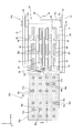
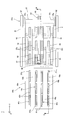
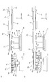
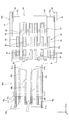
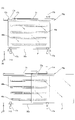
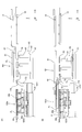
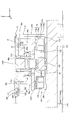
- FIG. 2 is a plan view of a substrate stage (substrate holder), a substrate carry-in device, and a substrate carry-out device that the liquid crystal exposure apparatus of FIG. 1 has.
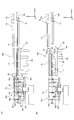
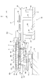
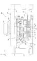
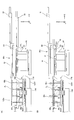
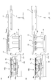
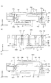
- FIG. FIG. 3 is a cross-sectional view taken along line AA of the substrate stage of FIG. 2.
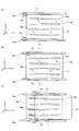
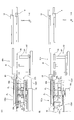
- FIGS. 4A and 4B are views (No. 1 and No. 2) for explaining the substrate replacement operation in the first embodiment.
- FIGS. 5A and 5B are views (No. 3 and No. 4) for explaining the substrate replacement operation in the first embodiment.
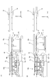
- FIGS. 6A and 6B are views (No. 5 and No. 6) for explaining the substrate replacement operation in the first embodiment.
- FIGS. 7A and 7B are views (No. 7 and No. 8) for explaining the substrate replacement operation in the first embodiment.
- FIGS. 8A and 8B are views (No. 9 and No. 10) for explaining the substrate replacement operation in the first embodiment.
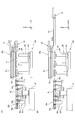
- It is a top view of the substrate stage (substrate holder), substrate carrying-in device, and substrate carrying-out device concerning a 2nd embodiment.
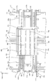
- FIG. 10 is a sectional view taken along line BB in FIG. 9. It is a figure which shows schematically the structure of the liquid-crystal exposure apparatus of 3rd Embodiment.
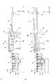
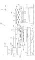
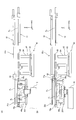
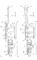
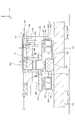
- FIG. 12 is a plan view of a substrate stage (substrate holder), a substrate carry-in device, and a port unit included in the liquid crystal exposure apparatus of FIG. 11.
- FIG. 12 is a plan view of a substrate stage (substrate holder), a substrate carry-in device, and a port unit included in the liquid crystal exposure apparatus of FIG. 11.
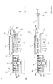
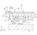
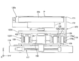
- FIG. 13 is a cross-sectional view of the substrate stage of FIG. 12 (cross-sectional view taken along the line CC of FIG. 12).
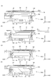
- FIGS. 14A and 14B are views (No. 1 and No. 2) for explaining the substrate replacement operation in the third embodiment.
- FIG. 15A and FIG. 15B are views (No. 3 and No. 4) for explaining the substrate replacement operation in the third embodiment.
- FIGS. 16A and 16B are views (No. 5 and No. 6) for explaining the substrate replacement operation in the third embodiment.
- FIGS. 17A and 17B are views (No. 7 and No. 8) for explaining the substrate replacement operation in the third embodiment.
- FIGS. 18A and 18B are views (No. 9 and No. 10) for explaining the substrate replacement operation in the third embodiment.
- FIG. 20A to 20C are views (No. 1 to No. 3) for explaining the operation of the substrate when the substrate is carried out according to the third embodiment. It is a top view of a substrate stage (substrate holder) concerning a 4th embodiment, a substrate carrying-in device, and a port part.
- FIG. 22 is a cross-sectional view of the substrate stage (substrate holder), substrate carry-in device, and port portion of FIG. 21.
- FIGS. 25A to 25C are views (No. 1 to No. 3) for explaining the substrate replacement operation in the sixth embodiment.
- FIGS. 26A to 26C are views (No. 1 to No. 3) for explaining the substrate replacement operation in the first modification.
- FIGS. 27A to 27C are views (No. 4 to No. 6) for explaining the substrate replacement operation in the first modified example.
- FIGS. 29A and 29B are views (No. 1 and No. 2) for explaining the substrate replacement operation in the third modification.
- FIGS. 30A and 30B are diagrams (No. 3 and No. 4) for explaining the substrate replacement operation in the third modified example. It is a figure which shows schematically the structure of the liquid crystal exposure apparatus which concerns on 7th Embodiment.
- FIG. 32 is a plan view of a substrate stage device included in the liquid crystal exposure apparatus of FIG. 31. It is the side view which looked at the substrate stage apparatus of FIG. 32 from the + Y side.
- FIG. 34 is a cross-sectional view of the substrate stage apparatus of FIG. 33 taken along the line EE.
- FIG. 36A and FIG. 36B are views (No. 1 and No. 2) for explaining the substrate replacement operation in the seventh embodiment.
- FIGS. 37A and 37B are views (No. 3 and No. 4) for explaining the substrate replacement operation in the seventh embodiment.
- FIGS. 38A and 38B are views (No. 5 and No. 6) for explaining the substrate replacement operation in the seventh embodiment.
- FIGS. 39A and 39B are views (No. 7 and No. 8) for explaining the substrate replacement operation in the seventh embodiment.
- FIGS. 40A and 40B are views (No. 9 and No. 10) for explaining the substrate replacement operation in the seventh embodiment.
- FIGS. 41A and 41B are views (No. 11 and No. 12) for explaining the substrate replacement operation in the seventh embodiment. It is a top view of the substrate stage which concerns on 8th Embodiment, Comprising: It is a figure which shows the state before board
- FIG. 43 is a cross-sectional view of the substrate stage of FIG. 42. It is a top view of the substrate stage which concerns on 8th Embodiment, Comprising: It is a figure which shows the state at the time of board
- FIG. 45 is a cross-sectional view of the substrate stage of FIG. 44. It is a figure which shows the substrate stage which concerns on a 4th modification.
- FIG. 48A is a sectional view taken along line FF in FIG. 47
- FIG. 48B is a sectional view taken along line GG in FIG. 48A
- FIG. 48C is a fifth modified example. It is a figure for demonstrating operation
- 49A and 49B are views (No. 1 and No. 2) showing the internal structure of the substrate lift apparatus of FIG. 50 (A) to 50 (D) are views (Nos. 1 to 4) for explaining the loading and unloading operations of the substrate in the substrate stage according to the fifth modification.
- 51A and 51B are views (No. 1 and No. 2) showing a substrate lift device according to a sixth modification. It is a figure which shows the substrate stage apparatus which concerns on a 7th modification. It is a figure which shows the substrate stage apparatus which concerns on the 8th modification.
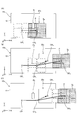
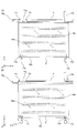
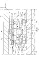
- FIG. 1 schematically shows the configuration of the liquid crystal exposure apparatus 10a of the first embodiment.
- the liquid crystal exposure apparatus 10a is a projection exposure apparatus that uses a rectangular (square) glass substrate P (hereinafter simply referred to as a substrate P) used for a liquid crystal display device (flat panel display) or the like as an exposure target.
- a substrate P rectangular glass substrate P
- a liquid crystal display device flat panel display
- the liquid crystal exposure apparatus 10a holds an illumination system IOP, a mask stage MST that holds a mask M, a projection optical system PL, and a substrate P on which a surface (a surface facing + Z side in FIG. 1) is coated with a resist (sensitive agent).
- a substrate stage device PSTa a substrate carry-in device 80a, a port unit 90 for transferring a substrate to and from an external device, and a control system thereof.
- the direction in which the mask M and the substrate P are relatively scanned with respect to the projection optical system PL at the time of exposure is defined as the X-axis direction
- the direction orthogonal to the X-axis in the horizontal plane is defined as the Y-axis direction, X-axis, and Y-axis.
- the direction orthogonal to the axis is defined as the Z-axis direction
- the rotation directions around the X-axis, Y-axis, and Z-axis are described as the ⁇ x, ⁇ y, and ⁇ z directions, respectively.
- description will be made assuming that the positions in the X-axis, Y-axis, and Z-axis directions are the X position, the Y position, and the Z position, respectively.
- the illumination system IOP is configured similarly to the illumination system disclosed in, for example, US Pat. No. 6,552,775. That is, the illumination system IOP emits light emitted from a light source (not shown) (for example, a mercury lamp) through exposure mirrors (not shown), dichroic mirrors, shutters, wavelength selection filters, various lenses, and the like. Irradiation light) is applied to the mask M as IL.
- a light source for example, a mercury lamp
- Irradiation light is applied to the mask M as IL.
- the illumination light IL for example, light such as i-line (wavelength 365 nm), g-line (wavelength 436 nm), h-line (wavelength 405 nm), or the combined light of the i-line, g-line, and h-line is used.
- a mask M having a circuit pattern or the like formed on its pattern surface is held by suction, for example, by vacuum suction.
- the mask stage MST is mounted on a lens barrel surface plate 16 which is a part of the apparatus body (body), and has a predetermined length in the scanning direction (X-axis direction) by a mask stage drive system (not shown) including a linear motor, for example. While being driven by a stroke, it is slightly driven as appropriate in the Y-axis direction and the ⁇ z direction. Position information (including rotation information in the ⁇ z direction) of the mask stage MST in the XY plane is measured by a mask interferometer system including a laser interferometer (not shown).
- the projection optical system PL is disposed below the mask stage MST and supported by the lens barrel surface plate 16.
- the projection optical system PL is configured similarly to the projection optical system disclosed in, for example, US Pat. No. 6,552,775. That is, the projection optical system PL includes a plurality of projection optical systems in which the projection areas of the pattern image of the mask M are arranged in a staggered pattern, and has a single rectangular image field whose longitudinal direction is the Y-axis direction. It functions in the same way as the optical system (so-called multi-lens projection optical system).
- a bilateral telecentric equal magnification system that forms an erect image is used.
- the illumination light IL that has passed through the mask M causes the circuit of the mask M in the illumination area to pass through the projection optical system PL.
- a projected image (partial upright image) of the pattern is formed in the irradiation region (exposure region) of the illumination light IL conjugate to the illumination region on the substrate P.
- the pattern formed on the mask M is transferred to the shot area. That is, in this embodiment, the pattern of the mask M is generated on the substrate P by the illumination system IOP and the projection optical system PL, and the pattern is formed on the substrate P by exposure of the sensitive layer (resist layer) on the substrate P by the illumination light IL. Is formed.
- the substrate stage apparatus PSTa includes a surface plate 12 and a substrate stage 20 a disposed above the surface plate 12.
- the surface plate 12 is composed of a rectangular plate-like member in plan view (viewed from the + Z side), and the upper surface thereof is finished with a very high flatness.
- the surface plate 12 is mounted on a substrate stage frame 13 which is a part of the apparatus main body.
- the apparatus body including the substrate stage mount 13 is mounted on a vibration isolator 14 installed on the floor 11 of the clean room, whereby the mask stage MST, the projection optical system PL, etc. vibrate with respect to the floor 11. Separated.
- the substrate stage 20a is mounted on the X coarse movement stage 23X and the X coarse movement stage 23X, and together with the X coarse movement stage 23X, constitutes a so-called gantry-type XY two-axis stage device, the Y coarse movement stage 23Y and the Y coarse movement stage 23Y on the + Z side.
- Fine movement stage 21 disposed on (upper), substrate holder 30a for holding substrate P, weight canceling device 26 for supporting fine movement stage 21 on the surface plate 12 from below, and a plurality for separating substrate P from substrate holder 30a
- Substrate lift device 46a (not shown in FIG. 1, refer to FIG. 3).
- the X coarse movement stage 23X is formed of a rectangular member having a longitudinal direction in the Y-axis direction in a plan view, and a long hole-like opening (not shown) having a longitudinal direction in the Y-axis direction is formed at the center thereof. Yes.
- the X coarse movement stage 23X is mounted on a guide member (not shown) that extends in the X-axis direction and is installed on the floor 11 separately from the apparatus main body. For example, during a scanning operation during exposure, during a substrate replacement operation, etc. Are driven with a predetermined stroke in the X-axis direction by an X stage drive system including a linear motor.
- the Y coarse movement stage 23Y is made of a rectangular member in plan view, and an opening (not shown) is formed at the center thereof.
- the Y coarse movement stage 23Y is mounted on the X coarse movement stage 23X via a Y linear guide device 25.
- the Y coarse movement is performed by a Y stage drive system including a linear motor. It is driven with a predetermined stroke on the stage 23X in the Y-axis direction.
- the Y coarse movement stage 23Y is moved in the X-axis direction integrally with the X coarse movement stage 23X by the action of the Y linear guide device 25.
- the fine movement stage 21 is composed of a rectangular parallelepiped member having a substantially square shape in plan view.
- the fine movement stage 21 is controlled by a fine movement stage drive system including a plurality of voice coil motors (or linear motors) including a stator fixed to the Y coarse movement stage 23Y and a mover fixed to the fine movement stage 21.
- the moving stage 23Y is slightly driven in directions of six degrees of freedom (X axis, Y axis, Z axis, ⁇ x, ⁇ y, ⁇ z directions).
- a plurality of X voice coil motors 29x which overlap in the depth direction in FIG.
- a plurality of Y voice coil motors (not shown) and a plurality of Z voice coil motors 29z (for example, arranged at positions corresponding to the four corners of the fine movement stage 21) for finely driving the fine movement stage 21 in the Z-axis direction are included. .
- the fine movement stage 21 is guided to the Y coarse movement stage 23Y via the plurality of voice coil motors, so that the fine movement stage 21 and the Y coarse movement stage 23Y are along the XY plane in the X axis direction and / or the Y axis direction. Move with a predetermined stroke.
- the positional information of the fine movement stage 21 in the XY plane is obtained by using a movable mirror (an X movable mirror 22x having a reflective surface orthogonal to the X axis and a reflective surface orthogonal to the Y axis) fixed to the fine movement stage 21 via a mirror base 24.
- An unillustrated interferometer (an X interferometer that measures the X position of the fine movement stage 21 using an X moving mirror 22x) and a Y moving mirror And a Y interferometer that measures the Y position of fine movement stage 21).
- the configurations of the fine movement stage drive system and the substrate interferometer system are disclosed in, for example, US Patent Application Publication No. 2010/0018950.
- the fine movement stage 21 has a plurality of holes 21a that are open to the upper surface (+ Z surface) and the lower surface ( ⁇ Z surface) (through the Z-axis direction). It is formed at a position corresponding to each substrate lift device 46a.
- the mirror base 24 has a hole 24a corresponding to the substrate lift device 46a.
- the substrate holder 30a is formed of a rectangular parallelepiped member having a rectangular shape in plan view with the X-axis direction as a longitudinal direction, and is fixed on the upper surface of the fine movement stage 21. A plurality of holes (not shown) are formed on the upper surface of the substrate holder 30a.
- the substrate holder 30a can be selectively connected to a vacuum device and a compressor (each not shown) provided outside the substrate stage 20a, and the substrate P (not shown in FIG. 3; not shown) by the vacuum device. Reference) is adsorbed and held, and the pressurized gas supplied from the compressor is ejected, whereby the substrate P can be floated through a minute clearance. Note that the suction and ejection of the gas may be performed using a common hole, or a dedicated hole may be used for each.
- a plurality of holes 31a that open (penetrate in the Z-axis direction) on the upper surface (+ Z surface) and the lower surface ( ⁇ Z surface) correspond to each of a plurality of substrate lift devices 46a described later. Formed in position. Further, as can be seen from FIGS. 2 and 3, a notch 32 that opens to the + Z side and the + X side is formed at the + X side end of the upper surface of the substrate holder 30a and at the center in the Y-axis direction. ing.
- the weight canceling device 26 is composed of a single columnar member extending in the Z-axis direction (also referred to as a core column), and a fine movement stage via a device referred to as a leveling device 27.
- the center portion of 21 is supported from below.
- the weight cancellation device 26 is inserted into the opening of each of the X coarse movement stage 23X (not shown in FIG. 3; see FIG. 1) and the Y coarse movement stage 23Y.
- the weight canceling device 26 floats on the surface plate 12 through a small clearance via a plurality of air bearings 26a attached to the lower surface portion thereof.
- the weight cancellation device 26 is connected to the Y coarse movement stage 23Y via a plurality of coupling devices 26b at the center of gravity height position in the Z-axis direction, and is pulled by the Y coarse movement stage 23Y. It moves on the surface plate 12 in the Y-axis direction and / or the X-axis direction together with the moving stage 23Y.
- the weight canceling device 26 has, for example, an air spring (not shown), and the weight of the system including the fine movement stage 21, the leveling device 27, and the substrate holder 30a (vertically downward) by the upward force generated by the air spring. This reduces the load on the plurality of voice coil motors of the fine movement stage drive system.
- the leveling device 27 supports the fine movement stage 21 from below so as to be swingable (tilt operation) with respect to the XY plane.
- the leveling device 27 is supported in a non-contact manner from below on the weight cancellation device 26 via an air bearing (not shown).
- the amount of tilt information of the fine movement stage 21 with respect to the XY plane is obtained by using a target 26d attached to the weight cancellation device 26 by a plurality of Z sensors 26c attached to the lower surface of the fine movement stage 21.
- the detailed configuration and operation of the weight cancellation device 26 including the leveling device 27 and the coupling device 26b are disclosed in, for example, US Patent Application Publication No. 2010/0018950.
- Each of the plurality of substrate lift devices 46a is fixed to the upper surface of the Y coarse movement stage 23Y, the Z actuator 47, the position protruding from the upper surface (substrate mounting surface) of the substrate holder 30a to the + Z side by the Z actuator 47, and the substrate holder 30a.
- a lift pin 48a driven in the Z-axis (vertical) direction between the upper surface and the position retracted to the -Z side.
- the substrate lift device 46a includes lift pins 48a, and the vicinity of the + Z side end thereof is formed in the hole 21a formed in the fine movement stage 21 (or the hole 24a formed in the mirror base 24) and the substrate holder 30a. Is inserted into the hole 31a.
- a gap is set between the substrate lift device 46a and the wall surface defining the holes 21a, 24a, 31a so that the fine movement stage 21 does not come into contact with each other when the fine movement stage 21 is slightly driven on the Y coarse movement stage 23Y. ing.
- the plurality of substrate lift devices 46a can support the lower surface of the substrate P substantially evenly. In this way, they are spaced apart from each other at a predetermined interval.
- a plurality of (for example, four) substrate lift device rows each including a plurality of (for example, four) substrate lift devices 46a arranged at predetermined intervals in the Y-axis direction are provided at predetermined intervals in the X-axis direction. It is arranged.
- the substrate P is separated (lifted) from the substrate holder 30a by using, for example, 24 substrate lift devices 46a, but the number and arrangement of the substrate lift devices 46a are not limited thereto. It is not limited, and can be appropriately changed according to the size of the substrate P, for example.
- the type of the Z actuator 47 is not particularly limited, and for example, an air cylinder device, a feed screw device, a cam device, or the like can be used.
- the substrate carry-in device 80a is disposed above (+ Z side) a port unit 90 described later.
- the substrate carry-in device 80 a includes a pair of X travel guides 81, a pair of X slide members 82 provided corresponding to the pair of X travel guides 81, and a pair of X slide members 82.
- An arranged road hand 83 is provided.
- the pair of X traveling guides 81 are each composed of a member extending in the X-axis direction, and the longitudinal dimension thereof is set to be somewhat longer than the X-axis dimension of the substrate P.
- the pair of X traveling guides 81 are arranged in parallel to each other at a predetermined interval in the Y-axis direction (spacing slightly larger than the dimension of the substrate P in the Y-axis direction).
- Each of the pair of X slide members 82 is engaged with the corresponding X traveling guide 81 so as to be slidable in the X axis direction, and by an actuator (not shown) (for example, a feed screw device, a linear motor, a belt driving device, etc.). , And are driven synchronously with a predetermined stroke along the X travel guide 81.
- Loading hand 83 includes a base portion 83 1 is a parallel plate-like portion to the XY plane extending in the Y-axis direction, a plurality of (e.g. four) is a X-axis direction parallel to the plate-like portion to the XY plane extending and a support portion 83 2.
- Longitudinal (Y-axis direction) dimension of the base portion 83 1 is set somewhat shorter than the dimension in the Y-axis direction of the substrate P.
- a plurality of support portions 83 2 are disposed parallel to each other at predetermined intervals in the Y-axis direction, the ends of each of the + X side is integrally connected to the -X side end of the base portion 83 1.
- a base portion 83 1, and the plurality of support portions 83 2, are integrally formed by, for example, CFRP (Carbon Fiber Reinforced Plastics).
- the longitudinal direction (X-axis direction) dimension of the plurality of support portions 83 2 is set somewhat shorter than the dimension in the X-axis direction of the substrate P, the substrate P includes the -X side of the area of the base portion 83 1 by a plurality of support portions 83 2, is supported from below.
- the Z position of the road hand 83 is set to the ⁇ Z side with respect to the X travel guide 81 as shown in FIG.
- the plurality of support portions 83 2 each of the upper surfaces, the suction pads 84 of a plurality arranged in a predetermined interval in the X-axis direction (for example, three) are mounted.
- a vacuum device (not shown) is connected to the load hand 83, and the substrate P can be sucked and held using the plurality of suction pads 84.
- Loading hand 83, the base portion 83 1 of the + Y side end portion of the -Y side via an attachment member 83 3 + Y side are respectively connected to the X slide member 82 on the -Y side, a pair of X slide member
- the substrate P is moved between the region above the port portion 90 shown in FIG.
- the load hand 83 may be configured to move up and down with respect to the pair of X traveling guides 81 (or integrally with the pair of X traveling guides 81).
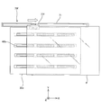
- the port unit 90 includes a gantry 91, a plurality of guide members 92, and a substrate carry-out device 93.
- the gantry 91 is installed on the floor 11 at a position on the + X side of the surface plate 12, and is housed in a chamber (not shown) together with the substrate stage device PSTa.
- Each of the plurality of guide members 92 is composed of a plate-like member parallel to the XY plane, and supports the substrate P from below.
- Each of the plurality of guide members 92 is synchronously driven in the Z-axis (vertical) direction by a Z actuator 94 fixed on the gantry 91.
- a plurality of minute holes are formed on the upper surface of the guide member 92, and pressurized gas (for example, air) is ejected from the holes to support the substrate P in a floating manner through a minute clearance. Be able to.
- the guide member 92 can also hold the substrate P by suction using the plurality of holes (or other holes).
- the plurality of guide members 92 are spaced apart from each other at a predetermined interval so that the lower surface of the substrate P can be supported almost evenly.
- a plurality (for example, four rows) of guide member rows composed of a plurality of (for example, three) guide members 92 arranged at predetermined intervals in the X-axis direction are arranged at predetermined intervals in the Y-axis direction.
- the port portion 90 of the first embodiment supports the substrate P from below using, for example, 12 guide members 92 in total.
- each of the plurality of guide members 92 is in a state where the load hand 83 of the substrate carry-in device 80a is positioned above the port portion 90 (a state where the load hand 83 is positioned at the stroke end on the + X side). It is arranged so as not to overlap the position for a plurality of support portions 83 2 and the Y-axis direction of the load hand 83. Accordingly, when the plurality of guide members 92 are driven in the + Z direction in synchronization with the load hand 83 positioned above the port portion 90, the plurality of guide members 92 are in contact with the load hand 83. no, so that it can pass between the support portions 83 2 adjacent to each other.
- the intervals in the Y-axis direction of the plurality of substrate lift devices 46a included in the substrate stage 20a are substantially the same as the intervals in the Y-axis direction of the plurality of guide members 92, and the load hand 83 is located above the substrate holder 30a. state but located, when a plurality of lift pins 48a is driven in the + Z direction, the plurality of lift pins 48a without contacting the load hand 83, so as to be able to pass between the supporting portion 83 2 adjacent to each other It has become.
- the substrate carry-out device 93 includes an X traveling guide 95, a plurality of Z actuators 96 for moving the X traveling guide 95 up and down, and an X slide that moves on the X traveling guide 95 with a predetermined stroke in the X axis direction.
- a suction pad 98 attached to the member 97 and the X slide member 97 is provided.
- the X traveling guide 95 is composed of a member extending in the X-axis direction, and, as shown in FIG. 2, among the plurality of (for example, four rows) guide member rows, between the second row and the third row. Has been placed.
- two Z actuators 96 are provided apart from each other in the X-axis direction.
- the X slide member 97 is engaged with the X travel guide 95 so as to be slidable in the X-axis direction, and is driven by an actuator (not shown) (for example, a feed screw device, a linear motor, a belt drive device, etc.). Are driven at a predetermined stroke (a stroke approximately equal to the dimension of the substrate P in the X-axis direction).
- the suction pad 98 is made of a plate-like member parallel to the XY plane, and a vacuum suction hole is formed on the upper surface (the surface facing the + Z side).
- the X traveling guide 95 is driven by a plurality of Z actuators 96, whereby the X slide member 97 and the suction pad 98 are moved (vertically moved) in the Z-axis direction.
- the mask M is loaded onto the mask stage MST by a mask loader (not shown) under the control of a main controller (not shown).
- the substrate loading device 80a loads the substrate P onto the substrate holder 30a.
- alignment measurement is performed by the main controller using an alignment detection system (not shown), and after the alignment measurement, a step-and-scan exposure operation is sequentially performed on a plurality of shot areas set on the substrate. Is done. Since this exposure operation is the same as a conventional step-and-scan exposure operation, a detailed description thereof will be omitted.
- the substrate on which the exposure processing has been completed is carried out of the substrate holder 30a, and another substrate to be exposed next is transferred to the substrate holder 30a, whereby the substrate on the substrate holder 30a is exchanged, and a plurality of substrates are exchanged. An exposure operation or the like is continuously performed on the substrate.
- the exchange operation of the substrate P on the substrate holder 30a in the liquid crystal exposure apparatus 10a (for convenience, the plurality of substrates P will be referred to as substrate P 0 , substrate P 1 , substrate P 2 , substrate P 3 ) will be described with reference to FIGS. This will be described with reference to FIG.
- the following board replacement operation is performed under the control of a main controller (not shown).
- the substrate holder 30a of the substrate stage 20a the substrate P 1 is held. Further, the loading hand 83 of the substrate carry-in device 80a, after the substrate P 1 is unloaded from the substrate holder 30a, and then the substrate P that is to be carried to the substrate holder 30a 2 (the next substrate P 2) is Is retained. In addition, the exposed substrate P 0 is held on the transfer hand 19 of the substrate carry-out robot installed outside the liquid crystal exposure apparatus 10a (see FIG. 1).
- the shape of the transfer hand 19 of the substrate carry-out robot and the transfer hand 18 of the substrate carry-in robot to be described later are substantially the same as the load hand 83 of the substrate carry-in device 80a, but the load hand 83 becomes the X travel guide 81.
- the transport hand 19 and the transport hand 18 are supported (cantilevered) by the robot arms 19a and 18a in the vicinity of the + X side end, and the robot arms 19a and 18a It moves in the X-axis direction by being controlled appropriately.
- the main control unit among the plurality of shot areas set on the substrate P 1, after exposure for the last shot area has been completed, from the lower side of the substrate stage 20a projection optical system PL (see FIG. 1), a constant The position is moved to a position adjacent to the port section 90 (hereinafter referred to as a board replacement position) on the board 12 in the vicinity of the end on the + X side.
- the substrate stage 20a is positioned with respect to the Y-axis direction so that the Y position of the notch 32 and the Y position of the substrate carry-out device 93 substantially coincide as shown in FIG.
- the substrate replacement position is a substrate unloading position (object unloading position) where the substrate P held by the substrate holder 30a (substrate stage 20a) is unloaded from the substrate holder 30a (substrate stage 20a) as described later. be able to.
- the load hand 83 is driven in the -X direction as shown in FIG. 2 is located above the substrate replacement position.
- the X slide member 97 is driven in the ⁇ X direction on the X travel guide 95, and the suction pad 98 is inserted into the notch 32 of the substrate holder 30a located at the substrate replacement position.
- the substrate carry-out device 93 a plurality of Z actuators 96, to a position where the upper surface of the suction pad 98 is in contact with the lower surface of the substrate P 1, X running guide 95 and X
- the slide member 97 is driven in the + Z direction (the substrate holder 30a may be driven in the ⁇ Z direction).
- Suction pad 98 sucks and holds the end portion of the + X side on the lower surface of the substrate P 1.
- the substrate stage 20a together with the suction holding of the substrate P 1 is released by the substrate holder 30a, pressurized gas is injected to the lower surface of the substrate P 1 from the upper surface of the substrate holder 30a.
- the Z positions of the plurality of guide members 92 are controlled such that the Z position of the upper surface thereof is substantially the same as the Z position of the upper surface of the substrate holder 30a.
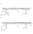
- the X slide member 97 is driven on the X travel guide 95 in the + X direction.
- the upper surface of the substrate P 1 is a substrate holder 30a sucked and held by the suction pad 98, and the + X direction along a plane parallel (guide surface) in the XY plane formed by the upper surface of the plurality of guide members 92
- it is carried out from the substrate holder 30a onto the plurality of guide members 92.
- pressurized gas is injected to the lower surface of the substrate P 1. This makes it possible to move the substrate P 1 high speed, low dust generation.
- the substrate carry-in device 80a When the substrate P 2 and load the hand 83 is spaced, as shown in FIG. 6 (B), the substrate carry-in device 80a, the load hand 83 is driven in the + X direction, it is retracted from above the substrate exchange position.
- the substrate carry-out device 93 In the substrate carry-out device 93, the X travel guide 95 and the X slide member 97 are driven in the ⁇ Z direction by the plurality of Z actuators 96. Thereby, a wide space is formed between the substrate carry-in device 80a and the substrate carry-out device 93. Further, a plurality of guide members 92 is also driven somewhat on the -Z side, the substrate P 1 is moved slightly in the -Z direction.
- the substrate P 0 is an external device that is placed on the conveying hand 19 of the substrate carry-out robot (e.g., coater developer device) while being conveyed, the conveying hand 18 of the substrate loading robot from an external device for the substrate P 2 Next come the substrate is conveyed P 3 that are to be carried to the substrate holder 30a.
- the substrate carry-out robot e.g., coater developer device
- the Z actuator 47 is synchronously controlled so that the lift pins 48a of each of the plurality of substrate lift devices 46a move in the ⁇ Z direction. 2 is placed on the upper surface of the substrate holder 30a.
- Z position of the lift pin 48a is controlled.
- Substrate P 2 is attracted to and held on the substrate holder 30a.
- transfer hand 18 of the substrate loading robot supporting the substrate P 3 is driven in the -X direction, between the pair of X running guide 81 of the substrate carry-in device 80a (see illustrated only one in FIG. 7 (A). FIG. 2) Inserted into.
- the conveyance hand 18 of the substrate loading robot and the load hand 83 of the substrate loading device 80a are arranged so as to overlap in the vertical direction.
- the transfer hand 19 of the substrate carry-out robot is driven in the ⁇ X direction and is inserted into the space between the load hand 83 and the substrate carry-out device 93.
- the transport hand 19 since the transport hand 19 has substantially the same shape as the load hand 83, it does not contact the guide member 92.
- the transfer hand 19 of the substrate carry-out robot and the load hand 83 of the substrate carry-in device 80 are arranged so as to overlap in the vertical direction.
- the substrate P 1 is delivered to the conveying hand 19 of the substrate carry-out robot.
- Transfer hand 19 supporting the substrate P 1, as shown in FIG. 7 (B), is driven in the + X direction, it conveys the substrate P 1 to an external device.
- the transport hand 19 drives the substrate unloading robot in the + Z direction to transfer the substrate P 1. You may receive it. Also, it may be performed to transfer the substrate P 1 by driving a plurality of guide members 92 and the substrate carry-out robot in the Z-direction, respectively.
- each of the plurality of guide members 92 After hands over the substrate P 1 to the conveying hand 19, each of the plurality of guide members 92, it is driven in synchronism with the + Z direction as shown in FIG. 8 (A). Each of the plurality of guide members 92 comes into contact with the lower surface of the substrate P 3 without contacting the load hand 83 and the transport hand 18, and is separated from the transport hand 18 by lifting the substrate P 3 .
- the transfer hand 18 of the substrate carry-in robot is driven in the + X direction and retreats from the area above the substrate carry-out device 93.
- each of the plurality of guide members 92 for supporting the substrate P 3 from below are driven in the -Z direction by the Z actuator 96.
- each of the plurality of guide members 92 while passing between the support portions 83 2 adjacent to each other in the loading hand 83, the substrate P 3 is supported from below on the supporting portion 83 2 of the load hand 83 (receiving Passed). This returns to the state shown in FIG.
- FIG. 7 (B) ⁇ FIG 8 (B), after Although the substrate stage 20a which holds the substrate P 2 are shown, the substrate P 2 adsorbed held (see FIG. 7 (A)), immediately substrate
- the alignment measurement and exposure processing may be started away from the exchange position.
- the upper surface of the substrate holder 30a is used as a guide surface for unloading the substrate P (the substrate P 1 in FIGS. 4A to 8B).
- the substrate carrying-out operation on the substrate holder 30a can be performed quickly. Further, when the substrate P is moved away from the substrate holder 30a for carrying out the substrate, the movement amount (rising amount) of the substrate P may be small. Accordingly, it is sufficient that there is a space in which the load hand 83 can be inserted above the substrate holder 30a of the substrate stage 20a in a state where the substrate stage 20a is positioned at the substrate exchange position.
- the substrate exchange system (including the substrate carry-in device 80a and the substrate carry-out device 93 using the upper surface of the substrate holder 30a as a part of the guide surface) of the first embodiment includes the substrate holder 30a and the lens barrel. Even when the space between the surface plate 16 (see FIG. 1) is narrow, it can be suitably used.
- the liquid crystal exposure apparatus according to the second embodiment is the same as the liquid crystal exposure apparatus 10a (see FIG. 1) of the first embodiment except for the configuration of the substrate holder 30b and the substrate lift device 46b. Only the points will be described, and elements having the same configuration and function as those of the first embodiment are denoted by the same reference numerals as those of the first embodiment, and description thereof will be omitted.
- the substrate P moves with the upper surface of the substrate holder 30a as a guide surface when the substrate is carried out (see FIGS. 5A and 5B), whereas the second embodiment.
- the difference is that the guide member 48b attached to the Z actuator 47 of each of the plurality of substrate lift devices 46b moves as a guide surface.
- X groove 31b 1 extending in the X-axis direction several (e.g. four) at predetermined intervals in the Y-axis direction are formed. Further, as shown in FIG. 10, through holes 31b 2 penetrating the substrate holder 30b in the vertical direction are formed on the bottom surface defining the X groove 31b 1 at predetermined intervals (for example, three) in the X axis direction. , in its through-hole 31b 2, a portion of the Z actuator 47 is inserted.
- Guide member 48b is (three for example) a plurality at predetermined intervals in the X-axis direction in one of the grooves 31b 1 are housed.
- the guide member 48b is composed of a plate-like member parallel to the XY plane.
- the Z actuator 47 causes the upper surface of the guide member 48b to protrude from the upper surface (substrate mounting surface) of the substrate holder 30b to the + Z side and the upper surface of the substrate holder 30b. It is driven in the Z-axis (vertical) direction between the position retracted to the Z side.
- a plurality of minute holes are formed on the upper surface of the guide member 48b.
- a pressurized gas for example, air
- the substrate P 1 can be levitated and supported. Further, the guide member 48b can also hold the substrate P by suction using the plurality of holes (or other holes).
- the plurality of holes or other holes.
- four X grooves 31b 1 are formed. However, the number of X grooves 31b 1 and the number and arrangement of the guide members 48b are not limited thereto. It can be appropriately changed according to the size of the.
- the suction and holding of the substrate P 1 by the substrate holder 30b is released.
- a plurality of guide members 48b are driven synchronously in the + Z direction, the lower surface of the substrate P 1 is separated from the upper surface of the substrate holder 30b.
- Suction pads 98 of the substrate carry-out device 93 is inserted between the upper and lower surfaces of the substrate P 1 of the substrate holder 30b.
- the substrate holder 30b of the second embodiment is not formed with the notch 32 unlike the substrate holder 30a of the first embodiment shown in FIG.
- the substrate P 2 is lowered to the plurality of guide members 48 b in place of the plurality of lift pins 48 a (see FIGS. 6A and 6B). Since it is the same as the first embodiment except that it is supported (adsorbed and held) from above (a plurality of guide members 48b also serve as a plurality of lift pins 48a), description thereof is omitted.
- FIGS. 11 to 20C a third embodiment will be described with reference to FIGS. 11 to 20C.
- the port portion 90 installed outside the substrate stage apparatus PSTa has the substrate carry-out device 93
- the liquid crystal exposure apparatus 10c according to the third embodiment is different in that the substrate stage 20c of the substrate stage apparatus PSTc has a substrate carry-out apparatus 70a.
- differences from the first embodiment will be mainly described, and elements having the same configurations and functions as those of the first embodiment will be described with respect to the first embodiment. The same reference numerals are given and description thereof is omitted.
- the liquid crystal exposure apparatus 10c of the third embodiment includes an illumination system IOP, a mask stage MST, a projection optical system PL, a substrate stage apparatus PSTc, a substrate carry-in apparatus 80c, a port unit 60, and a control system thereof.
- the substrate stage 20c of the substrate stage apparatus PSTc includes an X coarse movement stage 23X, a Y coarse movement stage 23Y, a fine movement stage 21, a substrate holder 30c, a weight cancellation device 26, and a plurality of substrate lift devices 46a (not shown in FIG. 11). See).
- the configuration of the substrate stage 20c is the same as that of the substrate stage 20a of the first embodiment (see FIG. 1 and the like) except that the substrate holder 30c has a substrate carry-out device 70a. Omitted.
- a plurality (for example, two) of X grooves 73x parallel to the X axis are formed at predetermined intervals in the Y axis direction on the upper surface (substrate mounting surface) of the substrate holder 30c.
- the X groove 73x opens on the side surfaces of the + X side and the ⁇ X side of the substrate holder 30c.
- a substrate carry-out device 70a is accommodated in each of the plurality of X grooves 73x.
- the substrate carry-out device 70a has an X travel guide 71 and a suction device 77a.
- the X traveling guide 71 is made of a member extending in the X-axis direction, and is fixed to the bottom surface that defines the X groove 73x as shown in FIG.
- the length in the longitudinal (X-axis) direction of the X traveling guide 71 is set longer than the dimension in the X-axis direction of the substrate holder 30c, and both end portions in the longitudinal direction protrude to the outside of the substrate holder 30c.
- the suction device 77a holds the suction pad 77a 1 for sucking and holding the lower surface of the substrate P (not shown in FIG. 13, see FIG. 11) and the suction pad 77a 1 in the vertical (Z-axis) direction on the X travel guide 71. and a Z actuator 77a 2 to be driven.
- the suction pad 77a 1 is made of a plate-like member parallel to the XY plane, and is connected to a vacuum device (not shown) installed outside the substrate stage 20c.
- the suction device 77a is slidably engaged with the X traveling guide 71 in the X axis direction, and is driven on the X traveling guide 71 with a predetermined stroke in the X axis direction.
- the type of drive device for driving the suction device 77a is not particularly limited.
- an X linear motor composed of a stator included in the X travel guide 71 and a mover included in the suction device 77a, or an X travel guide 71 is provided.
- a feed screw device including a feed screw having a nut and a nut of the suction device 77a can be used.
- a belt driving device that pulls the suction device 77a with a belt (or a rope) or the like may be used.
- the port unit 60 is installed on the + X side of the substrate stage apparatus PSTc, and is housed in a chamber (not shown) together with the substrate stage apparatus PSTc.
- the port unit 60 includes a gantry 61 and a substrate guide device 62.
- a plurality of substrate guide devices 62 are provided corresponding to the base 63, the plurality of Z actuators 64 mounted on the base 63, and the plurality of Z actuators 64, and driven in the vertical (Z-axis) direction by the corresponding Z actuator 64.
- the guide member 65 is provided.
- the base 63 is formed of a plate-like member having a rectangular shape in plan view parallel to the XY plane, and is fixed to the lower surface of the base 63 and a plurality of X linear guide members 66 fixed to the upper surface of the gantry 61. Are guided linearly in the X-axis direction by a plurality of X linear guide devices comprising X slide members 67 slidably engaged with each other.
- the base 63 is driven at a predetermined stroke in the X-axis direction by an X actuator (not shown) (for example, a feed screw device, a linear motor, etc.).
- X actuator for example, a feed screw device, a linear motor, etc.
- Z actuator 64 for example, a cam apparatus, a feed screw apparatus, an air cylinder etc. can be used.
- the plurality of Z actuators 64 are driven synchronously by a main controller (not shown).
- the guide member 65 is the same member as the guide member 92 (see FIG. 1 and the like) of the first embodiment, and can float and support the substrate P from below and hold the substrate P by suction.
- the arrangement of the plurality of Z actuators 64 and the plurality of guide members 65 included in the substrate guide device 62 will be described with reference to FIG.
- the Z actuator 64 is not shown hidden behind the guide member 65 (on the ⁇ Z side).
- illustrations of the gantry 61 and the base 63 are omitted.
- the plurality of guide members 65 are arranged such that the guide surface of the substrate P formed by the plurality of guide members 65 has a trapezoidal shape in plan view. More specifically, the substrate guide device 62 has, for example, three rows of guide members made up of a plurality of guide members 65 arranged at predetermined intervals in the Y-axis direction at predetermined intervals in the X-axis direction.
- the most-X side guide member row is configured by, for example, eight guide members 65.
- the middle guide member row of the three guide member rows is constituted by, for example, six guide members 65.
- the guide member row on the most + X side includes, for example, four guide members 65.
- the plurality of guide members 65 are arranged in a greater number in the ⁇ X side guide member row than in the + X side guide member row.
- the substrate P is moved downward in the Y-axis direction.
- the range that can be supported from the ⁇ X side (substrate stage 20c side) is wider than the + X side.
- the length (width) in the Y-axis direction of the most-X side (substrate stage 20a side) guide member row formed by the eight guide members 65 is the length (width) in the Y-axis direction of the substrate P. Longer than (for example, about 1.5 to 2 times).
- Each of the plurality of guide members 65 is in a state in which the load hand 83 of the substrate carry-in device 80c is positioned above the port portion 60 (see the guide member 92 (see FIG. 2) of the first embodiment) state) in which is positioned a loading hand 83 on the + X side of the stroke end, it is arranged so that they do not overlap positions for a plurality of support portions 83 2 and the Y-axis direction of the load hand 83.
- the shape, number, and arrangement of the plurality of guide members 65 are set such that the dimension in the Y-axis direction on the ⁇ X side of the guide surface defined by the plurality of guide members is larger than the dimension in the Y-axis direction of the substrate P. (If the guide surface is formed in a trapezoidal shape in plan view), the present invention is not limited to this, and can be changed as appropriate.
- the substrate carry-in device 80 c is arranged above the port portion 60 (+ Z side).
- Substrate carry-in device 80c of the third embodiment the spacing of the pair of X running guide 81 is wide, and the attachment member 83 3 is somewhat long for connection to a pair of X slide member 82 the load hand 83 Since the configuration is the same as that of the substrate carry-in device 80a (see FIG. 2) of the first embodiment, the description thereof is omitted here.
- the substrate P on the substrate holder 30c when the exposure operation or the like is continuously performed on the plurality of substrates P (for convenience, the plurality of substrates P is defined as the substrate P 0 , the substrate P 1 , the substrate P 2 , the substrate P 3). Will be described with reference to FIGS. 14A to 18B.
- the following board replacement operation is performed under the control of a main controller (not shown).
- the substrate stage 20c is shown in a cross-sectional view taken along the line DD of FIG. 12 in FIGS. 14A to 15A and FIGS. 16B to 18B. In FIG. 16B and FIG. 16A, a sectional view taken along the line CC of FIG.
- the substrate holder 30c of the substrate stage 20c the substrate P 1 is held. Further, the loading hand 83 of the substrate carry-in device 80c, after the substrate P 1 is unloaded from the substrate holder 30c, then the substrate P that is to be carried to the substrate holder 30c 2 (the next substrate P 2) is Is retained. In addition, the exposed substrate P 0 is held in the transfer hand 19 of the substrate transfer robot.
- the main control unit among the plurality of shot areas set on the substrate P 1, after exposure for the last shot area has been completed, as shown in FIG. 14 (B), the substrate stage 20c the projection optical system The substrate is moved to the substrate replacement position from below PL (see FIG. 11).
- the substrate stage 20c is in parallel with moving the substrate exchange position, the substrate carry-in device 80c, loading hand 83 is driven in the -X direction, thereby the substrate P 2 is positioned above the substrate exchange position.
- the base 63 is driven in the -X direction (direction approaching the substrate stage 20c) in order to narrow the gap (gap) between the most -X side guide member 65 and the substrate holder 30c.
- the Z positions of the plurality of guide members 65 on the base 63 are controlled so that the Z position of the upper surface thereof is substantially the same as the Z position of the upper surface of the substrate holder 30c.
- the main controller When the substrate stage 20c is located at the substrate exchange position, the main controller, as shown in FIG. 15 (A), together to release the suction holding the substrate P 1 by the substrate holder 30c, the pressure from the upper surface of the substrate holder 30c gas was allowed to ejected floating the substrate P 1. Further, for example, the suction pads 77a 1 (not shown in FIG. 15A, see FIG. 13) of the two substrate unloading devices 70a (one not shown in FIG. 15A) are driven in the + Z direction, and the substrate P The lower surface of 1 is held by suction.
- the suction device 77 a is driven in the + X direction on the X travel guide 71.
- the substrate P 1 sucked and held by the suction pad 77a 1 is aligned in the + X direction along a surface (guide surface) parallel to the XY plane formed by the upper surface of the substrate holder 30c and the upper surfaces of the plurality of guide members 65. It moves and is carried out to the port part 60 from the substrate holder 30c.
- pressurized gas is also ejected from the upper surfaces of the plurality of guide members 65. This makes it possible to move the substrate P 1 high speed, low dust generation.
- each of the plurality of substrate lift device 46a is controlled synchronously to move the lift pins 48a is in the + Z direction.
- each of the plurality of lift pins 48a passes between the supporting portion 83 2 of the loading hand 83 to press the lower surface of the substrate P 2 from below.
- the loading hand 83 suction holding of the substrate P 2 by the plurality of suction pads 84 is released.
- the substrate P 2 is separated from the load hand 83.
- the port portion 60 is driven to the substrate P 1 to a substrate guide device 62 which supports (base 63) + X direction (direction away from the substrate stage 20c).
- the substrate P 2 and load the hand 83 When the substrate P 2 and load the hand 83 is spaced, as shown in FIG. 16 (B), it is driven to load the hand 83 is the + X direction, and retreated from above the substrate exchange position, above the position of the port portion 60 Return. Furthermore, the port portion 60, a plurality of guide members 65 are driven somewhat on the -Z side, the substrate P 1 is moved slightly in the -Z direction. Further, the substrate P 0 that is placed on the conveying hand 19 of the substrate carry-out robot is transported to an external device, transfer hand 18 of the substrate loading robot comes to transporting the next substrate P 3 from the external device.
- each of the plurality of substrate lift device 46a is controlled synchronously so that the lift pins 48a is moved in the -Z direction, thereby the substrate P 2 is the substrate holder 30c is placed on the upper surface of (being separated from the lower surface of the lift pin 48a and the substrate P 2).
- Substrate P 2 is attracted to and held on the substrate holder 30c.
- the suction device 77 a located near the + X side end of the X travel guide 71 is in the ⁇ X direction. To return to a position on the vicinity of the ⁇ X side end of the X travel guide 71.
- the conveying hand 18 of the substrate loading robot supporting the substrate P 3 is driven in the -X direction, a pair of X running guide 81 of the substrate carry-in device 80c (FIG. 17 (A) In the not shown (See FIG. 12).
- the conveyance hand 18 of the substrate loading robot and the load hand 83 of the substrate loading device 80c are arranged so as to overlap each other in the vertical direction.
- transfer hand 19 of the substrate carry-out robot is driven in the -X direction, it is inserted into the lower substrate P 1.
- the transport hand 19 since the transport hand 19 has substantially the same shape as the load hand 83, it does not contact the guide member 65.
- the conveyance hand 19 of the substrate carry-out robot and the load hand 83 of the substrate carry-in device 80c are arranged so as to overlap in the vertical direction.
- the substrate P 1 is delivered to the conveying hand 19 of the substrate carry-out robot.
- Transfer hand 19 supporting the substrate P 1, as shown in FIG. 17 (B), is driven in the + X direction, it conveys the substrate P 1 to an external device.
- each of the plurality of guide members 65 are driven in synchronism with the + Z direction as shown in FIG. 18 (A).
- Each of the plurality of guide members 65 faces the lower surface of the substrate P 3 without contacting the load hand 83 and the transport hand 18, and is separated from the transport hand 18 by lifting the substrate P 3 .
- the substrate P 3 is attracted and held by the plurality of guide members 65.
- the transfer hand 18 of the substrate loading robot is driven in the + X direction and retreats from the area above the port unit 60.
- each of the plurality of guide members 65 for supporting the substrate P 3 from below are driven synchronously in the -Z direction.
- the substrate P 3 is supported from below on the supporting portion 83 2 of the load hand 83.
- the substrate P 3 is passed to the load hand 83 from the guide member 65, the state (but shown in FIG. 14 (A), the substrate P 0 is the substrate P 1, the substrate P 1 is the substrate P 2, a substrate the P 2 is the substrate P 3, back to are replaced respectively).
- the same effect as that of the first embodiment can be obtained.
- the substrate stage 20c has the substrate carry-out device 70a, the exposure process to the final shot area is completed before the substrate stage 20c reaches the substrate exchange position, that is, the substrate.
- the unloading operation of the substrate P can be started in parallel with the movement. Therefore, the cycle time for exchanging the substrate on the substrate holder 30c can be shortened, and the number of substrates P processed per unit time can be increased.
- the shot area where the exposure process is performed last is the + Y side of the substrate P in order to reduce the total movement amount of the substrate P (substrate stage 20c). Or on the -Y side. Accordingly, the substrate stage 20c after the exposure processing for the last shot region is completed moves in the X-axis direction when moving to the substrate exchange position, and also moves in the Y-axis direction (oblique with respect to the X-axis). Move in the direction of On the other hand, in the third embodiment, as shown in FIG. 19, among the plurality of guide members 65, the Y of the guide member row including, for example, eight guide members 65 arranged on the most ⁇ X side.
- the dimension in the axial direction is set to be longer than the dimension in the Y-axis direction of the substrate P, even when the substrate stage 20c moves in an oblique direction with respect to the X-axis, the substrate holder 30c of the substrate P The portion protruding from the + X side end is supported from below by the guide member 65. Thereby, the board
- 20A to 20C illustration of the substrate carry-out device 70a, the port unit 60 (see FIG. 12 respectively), etc. is omitted.
- 20A to 20C the irradiation area (exposure area) is described with the same reference numerals as those of the projection optical system PL (see FIG. 11) for convenience.
- the last shot area is a shot area S 6 set on the + Y side and the + X side of the substrate P. is there.
- the center of the substrate P before the start of the exposure operation for the shot areas S 6 is located at the position CP 1, the center of the substrate P when the exposure operation is completed, located at position CP 2.
- the substrate P is unloaded when the substrate P is unloaded. Since it moves parallel to the X-axis direction, the Y-position control of the substrate stage 20c is performed so that the center in the Y-axis direction of the most -X side guide member row and the center in the Y-axis direction of the substrate P substantially coincide with each other. In this case, the center of the substrate holder 30c passes through the position CP 1 ⁇ CP 2 ⁇ CP 4 (position CP 4 is the substrate replacement position) in FIG. It is necessary to perform position control.
- the + X side end of the substrate P is supported by the guide member 65 (see FIG. 19) regardless of the Y position of the substrate stage 20c.
- the substrate P can be carried out in parallel with the movement, and the center of the substrate P Can be carried out so that the substrate P passes through the position CP 1 ⁇ CP 2 ⁇ CP 3 in FIG. 20B (the center of the substrate stage 20c is CP 1 ⁇ CP 2 ⁇ CP 4 ). Go through the order). Therefore, the carrying-out operation of the substrate P can be performed quickly.
- the substrate stage 20c is positioned at the substrate exchange position, the substrate P moves in parallel to the X axis as shown in FIG.
- the substrate P moves with the upper surface of the substrate holder 30c as a guide surface when the substrate is unloaded (see FIGS. 15A and 15B), whereas the book shown in FIG.
- the substrate P is unloaded along the guide surface formed by the plurality of guide members 48b (see FIG. 22).
- the configuration of the substrate carry-out device 70a is the same as that of the third embodiment. Further, as shown in FIG. 22, since the configuration of the substrate lift device 46b including the guide member 48b is the same as that of the second embodiment, description thereof is omitted here.
- the substrate holder 30d can be reduced in weight.
- the substrate holders 30c and 30d (see FIGS. 12 and 21 respectively) have the substrate carry-out device 70a.
- FIG. the substrate stage 20e has a substrate carry-out device 70a outside the substrate holder 30e and on each of the + Y side and the ⁇ Y side of the substrate holder 30e.
- the configuration of each of the two substrate carry-out devices 70a is the same as that in the third embodiment.
- the amount of protrusion (protrusion) of the substrate P from the + Y side and ⁇ Y side ends of the substrate holder 30e is set larger than that in the third and fourth embodiments.
- One substrate carry-out device 70a is disposed below the portion of the substrate P protruding from the substrate holder 30e to the + Y side, and the other substrate carry-out device 70a is disposed on the ⁇ Y side from the substrate holder 30e of the substrate P. It is arranged below the protruding part.
- each of the two substrate carry-out devices 70a is provided via a support member fixed to the upper surface of the Y coarse movement stage 23Y (see FIG. 11) disposed below the substrate holder 30e.
- the Y coarse movement stage 23Y is attached. That is, for example, each of the two substrate carry-out devices 70a is arranged separately from the substrate holder 30e.
- each of the two substrate carry-out devices 70a is arranged outside the substrate holder 30e, so that a groove for accommodating the substrate carry-out device 70a must be formed in the substrate holder 30e. Therefore, a decrease in rigidity of the substrate holder 30e can be suppressed. Further, since the substrate P can be sucked and held in a wider area, the flatness of the substrate P can be improved. Moreover, since the substrate holder 30e can be reduced in weight and the reaction force when driving the suction device 77a does not act on the substrate holder 30e, the position controllability of the substrate holder 30e (substrate P) is improved. Moreover, since the board
- FIGS. 24 to 25C a sixth embodiment will be described with reference to FIGS. 24 to 25C.
- the configuration of the substrate carry-out device 70a is the same as that in the third embodiment.
- the configuration of the device 70d is different. Since the portion excluding the configuration of the substrate carry-out device 70d is the same as that of the fifth embodiment, only differences will be described below, and elements having the same configuration and function as those of the fifth embodiment will be described below.
- the same reference numerals as those in the fifth embodiment (or the third and fourth embodiments) are attached, and the description thereof is omitted.
- the substrate is placed on each of the + Y side and the ⁇ Y side of the substrate holder 30e as in the fifth embodiment (see FIG. 23).
- the carry-out device 70d is arranged separately from the substrate holder 30e.
- the substrate carry-out device 70d is movable on the support member 28 fixed on the upper surface of the Y coarse movement stage 23Y from below, and on the X travel guide 71 with a predetermined stroke in the X-axis direction.
- a Y linear guide device 78 and a suction device 77d mounted on the X travel guide 71 via the Y linear guide device 78 are provided.
- Adsorber 77d includes a suction pad for attracting and holding the lower surface of the substrate P 1.
- the Y linear guide device 78 has a Y actuator (not shown) so that the suction device 77d can be driven with a predetermined stroke in the Y-axis direction with respect to the X travel guide 71. Further, the Z position on the lower surface of the suction device 77d is located slightly on the + Z side from the Z position on the upper surface of the substrate holder 30e.
- the types of the X actuator that drives the Y linear guide device 78 in the X-axis direction and the Y actuator that drives the suction device 77d in the Y-axis direction are not particularly limited. For example, a feed screw device, a linear motor, or the like is used. be able to. Unlike the first to fifth embodiments, the suction device 77d does not have a Z actuator that drives the suction pad in the Z-axis direction.
- the substrate P (substrate P 1 in FIG. 24) is lifted from the upper surface of the substrate holder 30e, and then, as shown in FIG. 25B, for example, 2
- the suction device 77d of each of the two substrate carry-out devices 70d is driven in a direction approaching the substrate holder 30e (see the arrow in FIG. 25B).
- the inserted (see FIG. 24 to the lower surface of the substrate P of the suction device 77d is the substrate holder 30e.
- the upper surface of the lower surface and the substrate holder 30e adsorption device 77d is the substrate P 1 Inserted between).
- the plurality of guide members 48b are lowered in the substrate holder 30e, thereby allowing the substrate P to be sucked and held by the suction device 77d.
- each of the two suction devices 77d that suck and hold the substrate P is driven to the + X side in synchronization as shown in FIG.
- substrate P is carried out toward the port part not shown from the board
- exchange operation between the substrate P 1 and the load hand 83 over the placed in another (next) the substrate P 2 on the substrate holder 30e shown in FIG. 24 is the same as the above second embodiment thereof Description is omitted.
- the suction device 77d can move in the Y-axis direction, the substrate P does not need to protrude greatly from both ends of the substrate holder 30e in the Y-axis direction, and the substrate P can be reduced in size.
- the suction device 77d is movable in the Y-axis direction with respect to the X travel guide 71, but is not limited to this, for example, FIG.
- the suction device 77d may be previously attached to the substrate holder 30e side from the X travel guide 71 (the substrate unloading apparatus 70e). Does not include a Y actuator that drives the suction device 77d in the Y-axis direction with respect to the X travel guide 71). In this case, as shown in FIG.
- the suction device 77d is positioned on the ⁇ X side of the substrate P, and the substrate P is placed after the exposure is completed.
- the substrate P After being lifted from the substrate holder 30e using the plurality of guide members 48b, it is inserted between the substrate holder 30e and the substrate P by being driven in the + X direction as shown in FIG. Thereafter, the substrate P is lowered, and the suction device 77d sucks and holds the substrate P and is driven in the + X direction as shown in FIG. Thereby, the board
- the suction device 77d is positioned on the + X side of the substrate P as shown in FIG. Then, when the exposure processing of the substrate P is completed and the substrate P is lifted from the substrate holder 30e by the plurality of guide members 48b for the unloading operation, the suction device 77d has the substrate as shown in FIG. It passes below P and returns to the initial position (position on the ⁇ X side of substrate P) shown in FIG. Then, as shown in FIG. 27C, the processing after FIG. 26B is repeated. According to the first modification, the structure and control of the substrate carry-out device 70e can be simplified.
- the substrate carry-out device 70d is disposed on both sides (+ Y side and ⁇ Y side) of the substrate holder 30e, but FIG. 28 (hereinafter referred to as a second modification).
- the substrate carry-out device 70f may be disposed only on one side (+ Y side or -Y side) of the substrate holder 30e.
- the suction holding surface of the suction pad that the suction device 77f has is held by the suction device 77a of the third to sixth embodiments (see, for example, FIG. 12) so that the substrate P can be sucked and held with a stronger suction holding force. Should be set widely.
- the suction device 77f may be movable in the Y-axis direction with respect to the X travel guide 71 as in the sixth embodiment, or from the X travel guide 71 as in the first modification. You may fix in the state protruded to the substrate holder 30e side.
- the suction pad is driven in the Z-axis direction or the Y-axis direction with respect to the substrate P so that the lower surface of the substrate P can be sucked.
- the present invention is not limited to this, and as shown in FIGS. 29A to 30B (hereinafter referred to as the third modification), the substrate P is moved with respect to the suction device 77g. May be.
- the substrate carry-out device 70g is arranged on the + Y side of the substrate holder 30e (the suction device 77g cannot move in the Y-axis direction).
- two positioning devices 17a are arranged apart from each other in the X-axis direction on the ⁇ Y side of the substrate holder 30e, and for example, one positioning device 17b is arranged on the + Y side of the substrate holder 30e.
- Each of the plurality of positioning devices 17a and 17b is mounted on a Y coarse movement stage 23Y (see FIG. 11) via a support member (not shown), and is disposed at substantially the same Z position as the substrate P (accordingly, X travel). It does not conflict with the guide 71).
- the positioning devices 17a and 17b have an actuator such as an air cylinder, for example, and press the end of the substrate P to control the position of the substrate P.
- the substrate P is moved in the + Y direction by two positioning devices 17a, for example, as shown in FIG. 29B in a state where the exposed substrate P is levitated and supported by the plurality of guide members 48b. Driven by. At this time, excessive movement due to inertia in the + Y direction of the substrate P is suppressed by the movement preventing pin 17c and the positioning device 17b attached to the suction device 77g.
- a plurality of notches 17d are formed on the upper surface of the substrate holder 30e to prevent conflict with the positioning device 17a.
- the positioning devices 17a and 17b are retracted from the substrate P as shown in FIG. As shown in B), the substrate P is sucked and held by the sucking device 77g and carried out of the substrate holder 30e.
- the substrate P moves relative to the substrate carry-out device 70g, the amount of protrusion of the substrate P from the substrate holder 30e can be reduced in advance.
- the substrate stages 20a to 20f of the first to sixth embodiments have a configuration in which the Y coarse movement stage 23Y is mounted on the X coarse movement stage 23X.
- the seventh embodiment shown in FIG. The substrate stage 120a of the liquid crystal exposure apparatus 100 is different in that the X coarse movement stage 123X is mounted on the Y coarse movement stage 123Y (the upper coarse movement stage moves in the scanning direction).
- the substrate carry-out device 170 is provided on the Y coarse movement stage 123Y (lower coarse movement stage).
- the apparatus main body 130 includes a lens barrel base plate 131, a pair of side columns 132, and a substrate stage mount 133.
- the lens barrel surface plate 131 is composed of a plate-like member arranged in parallel to the XY plane, and supports the projection optical system PL, the mask stage MST, and the like.
- the pair of side columns 132 are spaced apart in the Y-axis direction, and support the vicinity of the + Y side end and the vicinity of the ⁇ Y side end of the lens barrel base plate 131 from below.
- the substrate stage base 133 is composed of a member extending in the Y-axis direction, and as shown in FIGS.
- the + Y side column 132 is, for example, near the end of the + Y side of the two substrate stage platforms 133
- the ⁇ Y side column 132 is, for example, the ⁇ Y side of the two substrate stage platforms 133 It is mounted on the vicinity of the end of each.
- the vicinity of the end in the longitudinal direction of the substrate stage base 133 is supported from below by a vibration isolator 134 installed on the floor 11 of the clean room.
- the apparatus main body 130 and projection optical system PL, mask stage MST, etc.
- the substrate stage apparatus 200 includes a pair of base frames 114, an auxiliary base frame 115, and a substrate stage 120a as shown in FIG.
- One base frame 114 is on the + X side of the + X side substrate stage frame 133, the other base frame 114 is on the -X side of the -X side substrate stage frame 133, and the auxiliary base frame 115 is a pair of substrate stages. Between the pedestals 133, the substrate stage pedestals 133 are arranged at a predetermined distance (in a non-contact state).
- the pair of base frames 114 and auxiliary base frames 115 are each composed of a plate-like member parallel to the YZ plane extending in the Y-axis direction, and the height position (Z position) can be adjusted via a plurality of adjuster devices on the floor 11. Is installed. As shown in FIG.
- a mechanical Y linear guide device (single-axis guide device) extending in the Y-axis direction is provided on the upper end surfaces (+ Z side end portions) of the pair of base frames 114 and the auxiliary base frame 115, respectively.
- the Y linear guide 116a which is an element of the above is fixed.
- the substrate stage 120a includes a Y coarse movement stage 123Y, an X coarse movement stage 123X, a fine movement stage 21, a substrate holder 30b, a plurality of substrate lift devices 46b, a Y step surface plate 150, a weight cancellation device 26, and a substrate.
- a carry-out device 170 is included.
- Y coarse movement stage 123Y is mounted on a pair of base frames 114 and auxiliary base frame 115 as shown in FIG. As shown in FIG. 32, the Y coarse movement stage 123Y has a pair of X beams 125.
- Each of the pair of X beams 125 includes a member having a rectangular YZ section extending in the X-axis direction, and is arranged in parallel to each other at a predetermined interval in the Y-axis direction.
- the pair of X beams 125 are connected to each other by a Y carriage 126 in the vicinity of the + X side and ⁇ X side ends.
- the Y carriage 126 is composed of a plate-like member parallel to the XY plane extending in the Y-axis direction, and a pair of X beams 125 are mounted on the upper surface thereof. Further, as shown in FIG. 33, the pair of X beams 125 are connected at the center in the longitudinal direction by an auxiliary carriage 126a.
- a plurality of Y slide members 116b constituting the Y linear guide device 116 together with the Y linear guide 116a are provided on the lower surface of the Y carriage 126 and the lower surface of the auxiliary carriage 126a (FIG. 33). (It overlaps in the depth direction of the paper).
- the Y slide member 116b is slidably engaged with the corresponding Y linear guide 116a with low friction, and the Y coarse movement stage 123Y has a low friction on the pair of base frames 114 and the auxiliary base frame 115 with the Y axis. It can move in a direction with a predetermined stroke.
- the Z position of the lower surface of the pair of X beams 125 is set to the + Z side with respect to the upper surface of the pair of substrate stage stands 133, and the Y coarse movement stage 123Y is moved from the pair of substrate stage stands 133 (that is, the apparatus main body 130). Vibrationally separated.
- the Y coarse movement stage 123Y is driven in the Y-axis direction by a pair of Y feed screw devices 117 as shown in FIG.
- Each of the pair of Y feed screw devices 117 includes a screw shaft 117a that is driven to rotate by a motor attached to the outer surface of the base frame 114, and a nut having a plurality of circulating balls (not shown) attached to the Y carriage 126. 117b.
- the type of Y actuator for driving the Y coarse movement stage 123Y (the pair of X beams 125) in the Y-axis direction is not limited to the ball screw device, and may be, for example, a linear motor, a belt driving device, or the like. . Further, a Y actuator having the same configuration (or another type) as that of the Y feed screw device 117 may be disposed on the auxiliary base frame 115. Moreover, the Y feed screw device 117 may be one.
- an X linear guide 127a which is an element of a mechanical uniaxial guide device extending in the X-axis direction, is provided on each upper surface of the pair of X beams 125 at a predetermined interval in the Y-axis direction.
- a magnet unit 128a (X stator) including a plurality of permanent magnets arranged at predetermined intervals in the X-axis direction in the upper surface of each of the pair of X beams 125 and in a region between the pair of X linear guides 127a. Is fixed.
- the X coarse movement stage 123X is made of a plate member having a rectangular shape in plan view, and an opening is formed at the center thereof.
- An X slide member 127b that constitutes the X linear guide device 127 together with the X linear guide 127a is fixed to the lower surface of the X coarse movement stage 123X.
- four X slide members 127b are provided at predetermined intervals in the X-axis direction for each X linear guide 127a (see FIG. 33).
- the X slide member 127b is slidably engaged with the corresponding X linear guide 127a with low friction, and the X coarse movement stage 123X has a predetermined stroke in the X axis direction with low friction on the pair of X beams 125.
- the lower surface of the X coarse movement stage 123X is opposed to each of the pair of magnet units 128a via a predetermined clearance, and drives the X coarse movement stage together with the pair of magnet units 128a with a predetermined stroke in the X-axis direction.
- a pair of coil units 128b (X movers) constituting the pair of X linear motors 128 are fixed.
- the relative movement of the X coarse movement stage 123X in the Y axis direction with respect to the Y coarse movement stage 123Y is restricted by the X linear guide device 127, and moves in the Y axis direction integrally with the Y coarse movement stage 123Y. That is, the X coarse movement stage 123X and the Y coarse movement stage 123Y constitute a gantry-type two-axis stage device.
- the Y position information of the Y coarse movement stage 123Y and the X position information of the X coarse movement stage 123X are obtained by a linear encoder system (not shown).
- fine movement stage 21 (including the drive system and the measurement system) is the same as that of the first embodiment (including a plurality of voice coil motors 29x, 29y, and 29z) as shown in FIGS. (This includes a substrate interferometer system using a fine movement stage drive system and an X moving mirror 22x and a Y moving mirror 22y), and the description thereof is omitted here.
- X groove 31b 1 are opened at both ends of the substrate holder 30b, may not be opened.
- the configuration of the plurality of substrate lift devices 46b is substantially the same as that of the second embodiment, and the description thereof is omitted here.
- a plurality of (for example, four) substrate lift devices 46b are arranged at predetermined intervals in the X-axis direction, and the guide member 48b is shown in FIG. as shown, in response to one of the X grooves 31b 1, for example, four (in total, for example, 16 units) are accommodated.
- the Y-step surface plate 150 is composed of a member having a rectangular YZ section extending in the X-axis direction, and a pair of X-beams 125 are separated from each other by a predetermined distance (in a non-contact state). It is inserted between the X beams 125.
- the dimension in the longitudinal direction of the Y-step surface plate 150 is set slightly longer than the movement stroke of the fine movement stage 21 in the X-axis direction.
- the upper surface of the Y-step surface plate 150 is finished with very high flatness. As shown in FIG.
- the Y step surface plate 150 includes a plurality of Y linear guides 135 a fixed to the upper surfaces of the pair of substrate stage mounts 133 and a plurality of Y step surface plates 150 fixed to the lower surface of the Y step surface plate 150.
- a plurality of Y linear guide devices 135 constituted by the slide members 135b are guided linearly with a predetermined stroke on the pair of substrate stage platforms 133 in the Y-axis direction.
- the Y-step surface plate 150 is mechanically applied to a pair of X beams 125 via a pair of flexure devices 151 in the vicinity of the + X side and ⁇ X side ends. It is connected to. Thereby, the Y-step surface plate 150 and the Y coarse movement stage 123Y move integrally in the Y-axis direction.
- the flexure device 151 includes, for example, a thin strip-shaped steel plate arranged in parallel to the XY plane, and a sliding device (for example, a ball joint or a hinge device) provided at both ends of the steel plate. Is installed between the Y-step surface plate 150 and the X-beam 125 via a sliding device.
- the flexure device 151 has lower rigidity in the other five degrees of freedom directions (X, Z, ⁇ x, ⁇ y, ⁇ z directions) compared to the rigidity in the Y-axis direction.
- the Y coarse movement stage 123Y is vibrationally separated. Note that the Y position of the Y step surface plate 150 may be controlled independently of the Y coarse movement stage 123Y by an actuator such as a linear motor or a feed screw device.
- the weight canceling device 26 is in a non-contact state on the Y-step surface plate 150 via a plurality of air bearings 26a attached to the lower surface thereof. Since it is mounted, the dimension in the Z-axis direction is shorter than that in the first embodiment.
- the weight cancellation device 26 is mechanically connected to the X coarse movement stage 123X via a plurality of flexure devices 26b. When the weight cancellation device 26 moves together with the X coarse movement stage 123X in the X-axis direction, the Y step constant is determined. Move on the board 150.
- the weight cancellation device 26 moves in the Y axis direction integrally with the X coarse movement stage 123X
- the weight cancellation device 26 moves in the Y axis direction integrally with the Y coarse movement stage 123Y and the Y step surface plate 150.
- the Y-step surface plate 150 does not fall off.
- the substrate carry-out device 170 directs the substrate P placed on the substrate holder 30b to the outside of the substrate stage device 200 described later (in this embodiment, the substrate guide device 62 of the port unit 60 described later (see FIG. 35)). It is an apparatus to carry out, and is attached to the outer surface (surface facing the + Y side) of the + Y side X beam 125 of the pair of X beams 125.
- the substrate carry-out device 170 is a pair of X that linearly guides the suction pad 171 that sucks and holds the lower surface of the substrate P to be carried out, the support member 172 that supports the suction pad, and the support member 172 (and the suction pad 171) in the X-axis direction.
- FIG. 34 is a cross-sectional view taken along the line EE of FIG. 33, and is shown with the suction pad 171 and the support member 172 positioned at the stroke end on the ⁇ X side for the purpose of explaining the configuration of the substrate carry-out device 170. Has been.
- the suction pad 171 is made of a member having an inverted L-shaped YZ section, and a portion parallel to the XY plane is a plan view with the X-axis direction as the longitudinal direction, as shown in FIG. It consists of a rectangular plate-shaped member.
- the suction pad 171 is connected to a vacuum device (not shown) installed outside, and the upper surface of a portion parallel to the XY plane functions as a substrate suction surface portion.
- the support member 172 is composed of a plate-like member parallel to the XZ plane extending in the Z-axis direction, and a suction pad 171 is attached in the vicinity of its upper end (+ Z side end). .
- the support member 172 has a structure in which the rigidity in the X-axis direction is higher than the rigidity in the Y-axis direction.
- the support member 172 is formed such that a portion on the + Z side is bent slightly toward the + X side with respect to the center portion in the Z-axis direction, and an upper end portion of the support member 172 is + X side of a lower end portion ( ⁇ Z side end portion). (That is, protrudes to the port 60 (not shown in FIG. 33; see FIG. 35) side). Further, as shown in FIG.
- the substrate holder 30b is positioned between the support member 172 and the substrate holder 30b in the state where the support member 172 and the substrate holder 30b are adjacent to each other with respect to the X coarse movement stage 123X.
- the clearances are set so that they do not contact each other even if they are slightly driven in the direction and / or the ⁇ z direction.
- the suction pad 171 is connected to the support member 172 in the vicinity of the + Y side end, whereby the ⁇ Y side end from the surface of the support member 172 facing the ⁇ Y side (substrate holder 30b).
- the Y position of the end portion on the ⁇ Y side is located on the ⁇ Y side with respect to the end portion on the + Y side of the substrate holder 30b. That is, when the substrate stage 120a is viewed from the + Z side, the suction pad 171 is positioned above the substrate holder 30b (overlaps in the Z-axis direction), depending on the X position of the substrate holder 30b.
- the suction pad 171 has a lower Z position that is higher than a Z position on the upper surface of the substrate holder 30b (the Z position of the substrate holder 30b changes within a very small range.
- the support member 172 supports the substrate holder 30b so that it is positioned higher than the Z position on the upper surface of the substrate holder 30b. Accordingly, the suction pad 171 can be inserted between the substrate P and the substrate holder 30b in a state where the substrate P is driven up (lifted) from the upper surface of the substrate holder 30b by the plurality of substrate lift devices 46b. It is like that.
- One surface near the lower end of the support member 172 faces the outer surface of the X beam 125 on the + Y side.
- two (a pair) X linear guides 173a extending in the X axis direction are fixed to the outer surface of the + Y side X beam 125 at a predetermined interval in the Z axis direction.
- the length of the pair of X linear guides 173a (dimension in the X axis direction) is set to almost half of the X beam 125 (or about the same as the length of the substrate P in the X axis direction). It is arranged in a region on the + X side (port portion 60 (not shown in FIG. 33; see FIG.
- one surface of the support member 172 (the surface facing the X beam 125) includes a rolling element (not shown) (for example, a circulating ball) and is mechanically slidably engaged with the X linear guide 173a.
- a rolling element for example, a circulating ball
- two X sliders 173b are fixed to one X linear guide 173a at predetermined intervals in the X-axis direction.
- An X linear guide device 173 for linearly guiding the support member 172 (and the suction pad 171) in the X-axis direction is configured by the X linear guide 173a and, for example, two X sliders 173b corresponding to the X linear guide 173a. Has been.
- a magnet unit 174a including a plurality of permanent magnets arranged at a predetermined interval in the X-axis direction is fixed between the pair of X linear guides 173a.
- a coil unit 174b including a coil is fixed to one surface of the support member 172 (the surface facing the X beam 125) facing the magnet unit 174a at a predetermined interval.
- An X linear motor 174 for driving the support member 172 (and the suction pad 171) in the X-axis direction by the magnet unit 174a (X stator) and the coil unit 174b (X mover) corresponding to the magnet unit 174a. Is configured.
- the actuator for driving the support member 172 (and the suction pad 171) in the X-axis direction is not limited to this.
- a ball screw (feed screw) device for example, a ball screw (feed screw) device, a traction device using a rope (or belt, etc.), etc.
- Other uniaxial actuators may be used.
- stoppers 175 for mechanically defining the movable range of the support member 172 are fixed on the outer surface of the X beam 125 on the + Y side and in the vicinity of both ends of the magnet unit 174a.
- the plurality of Z actuators 47 are arranged such that the upper surface of the guide member 48b of each of the plurality of substrate lift devices 46b is located on the + Z side with respect to the upper surface of the substrate holder 30b. Be controlled.
- the suction pad 171 sucks and holds the lower surface of the substrate P in the vicinity of the ⁇ X side and + Y side end portions (corner portions), and the support member 172 is driven by the X linear motor 174 in this state.
- the substrate P moves in the + X direction on the substrate holder 30 b and is carried out to the port unit 60.
- pressurized gas is ejected from the plurality of guide members 48b to the lower surface of the substrate P, and the substrate P is supported in a floating manner.
- the substrate P moves on the substrate holder 30b with low friction.
- the X position of the suction pad 171 when the support member 172 is positioned at the stroke end on the + X side is the stroke of the X coarse movement stage 123X on the + X side.
- the shape (bending amount) of the support member 172 is set so as to be on the + X side of the substrate holder 30b when positioned at the end.
- the suction pad 171 can be retracted outside the movable range of the X coarse movement stage 123X while the exposure processing for the substrate P is performed.
- the intermediate portion of the support member 172 is bent, but if the suction pad 171 can be retracted outside the movable range in the X-axis direction of the substrate holder 30b, the support member 172 has a
- the shape is not limited to this.
- the configurations of the substrate carry-in device 80c and the port unit 60 (including the substrate guide device 62) shown in FIG. 35 are the same as those in the third embodiment, and a description thereof will be omitted here.
- the exchange operation of the substrate P on the substrate holder 30b in the liquid crystal exposure apparatus 100 (for convenience, the plurality of substrates P will be referred to as substrate P 1 , substrate P 2 , substrate P 3 ) will be described with reference to FIGS. ).
- the following board replacement operation is performed under the control of a main controller (not shown).
- the substrate holder 30b is shown in a sectional view and includes a plurality of voice coil motors and the like, and a part of the substrate stage 120a is shown. Is omitted.
- the substrate holder 30b of the substrate stage 120a the substrate P 1 is held.
- the load hand 83 holds a substrate P 2 (next substrate P 2 ) to be held next by the substrate holder 30 b after the substrate P 1 is unloaded from the substrate holder 30 b.
- the main control unit among the plurality of shot areas set on the substrate P 1, after exposure for the last shot area has been completed, as shown in FIG. 36 (B), the substrate from the exposure end position stage 120a To move to the substrate exchange position.
- the support member 172 of the substrate carry-out device 170 is positioned at the stroke end on the + X side, and the suction pad 171 is retracted outside the movable range in the X-axis direction of the substrate P. ing. Therefore, for unloading the substrate P 1, X coarse movement stage 123X (and substrate holder 30b) is also moved in the X-axis direction, not in contact with the substrate P 1 and the suction pad 171. In parallel with this, the load hand 83 is driven in the -X direction, thereby the substrate P 2 is positioned above the substrate exchange position. Further, in the port portion 60, the substrate guide device 62 is driven in a direction approaching the substrate stage 120a.
- the main controller As shown in FIG. 37 (A), together to release the suction holding of the substrate P 1 by the substrate holder 30b, control multiple substrate lift device 46b Then, the guide member 48b is driven up. Thus, a gap is formed between the lower surface of the substrate P 1, and the upper surface of the substrate holder 30b. Then, as shown in FIG. 37 (B), between the support member 172 of the substrate carry-out device 170 is driven in the -X direction, thereby the lower surface of the suction pad 171 is the substrate P 1, and the upper surface of the substrate holder 30b passes through the gap, the end of the -X side and + Y side of the substrate P 1 (corner) is located below the vicinity.
- a plurality of guide members 48b are driven downward, the lower surface of the substrate P 1 is sucked and held by the suction pad 171. Further, a plurality of guide members 48b floats supporting the substrate P 1 by ejecting the pressurized gas to the lower surface of the substrate P 1. At this time, the plurality of guide members 48b of the substrate stage 120a and the plurality of guide members 65 of the port portion 60 are controlled so that the Z positions of the upper surfaces thereof are substantially the same.
- the supporting member 172 of the substrate carry-out device 170 is driven in the + X direction, thereby, the suction pads 171 substrate P 1 sucked and held by the plurality of guide members 48b, And moves in the + X direction along a plane (guide surface) parallel to the XY plane formed by the upper surfaces of the plurality of guide members 65, and is carried out from the substrate holder 30 b to the port unit 60.
- pressurized gas is injected to the substrate P 1. This makes it possible to move the substrate P 1 fast and with low dust generation.
- a plurality of guide members 48b are driven upward to press the lower surface of the substrate P 2 from below.
- suction holding of the substrate P 2 is released, thereby, the substrate P 2 is separated from the load hand 83.
- may pass is lowered loading hand 83 receives the substrate P 2 to a plurality of guide members 48b.
- the substrate P 2 is adsorbed on the substrate holder 30b, the alignment operation, X coarse movement stage 123X in order to perform an exposure operation the port portion 60 about the substrate P 2 Driven in a direction away from Furthermore, the port portion 60, the substrate P 1 is recovered from the port portion 60 by the conveying hand 19 of the substrate carry-out robot, it is conveyed to an external device (not shown). Further, the plurality of guide members 65 are driven up. Transfer hand 18 of the substrate loading robot holds the substrate P 3.
- FIG. 40 (B) As transfer hand 18 of the substrate loading robot transports the substrate P 3 above the plurality of guide members 65, shown in FIG. 41 (A), the substrate P 3 is transferred to a plurality of guide members 65. Thereafter, as shown in FIG. 41 (B), a plurality of guide members 65 is driven downward, the substrate P 3 is placed on the loading hand 83 (returns to the state shown in FIG. 36 (A)). At this time, alignment (alignment) with respect to the load hand 83 may be performed in a state where the substrate P 3 is floated on the plurality of guide members 65. The alignment is performed, for example, by pressing the substrate P 3 at a plurality of positions on the end while detecting the end (edge) position of the substrate P 3 with an edge sensor or a camera.
- the substrate carry-out device 170 is attached to the Y coarse movement stage 123Y that is stationary during the scanning operation in the substrate stage 120a, The position control of the stage 123X is not affected, and the X position of the substrate P can be controlled with high accuracy during the scanning operation.
- the substrate stage 120a has a structure in which the X coarse movement stage 123X and the fine movement stage 21 are mounted on the Y coarse movement stage 123Y having the substrate carry-out device 170 (a structure in which the Y coarse movement stage 123Y is at the bottom).
- the maintenance of the substrate carry-out device 170 is also easy.
- the substrate carry-out device 170 since the substrate carry-out device 170 only moves the suction pad 171 (and the support member 172) in the X-axis (one-axis) direction, the configuration and control are simple. For example, the cost is lower than that of an articulated robot arm. is there. Further, since the substrate carry-out device 170 can retract the suction pad 171 to the outside of the movable range in the X-axis direction of the substrate P, the height position between the suction pad 171 and the substrate P (or substrate holder 30b) ( Even if the Z position is the same, it is possible to prevent contact with each other.
- the substrate stage 120a has the substrate carry-out device 170, only the substrate carry-in device 80c for carrying the substrate P to the substrate stage 120a may be disposed in the port unit 60. That is, in the seventh embodiment, only the load hand 83 of the substrate carry-in device 80c is positioned above the substrate stage 120a positioned at the substrate replacement position during the replacement operation of the substrate held on the substrate stage 120a.
- the substrate holder 30b and the lens barrel surface plate are provided. Even if the space between the substrate 131 and the substrate 131 is narrow, the substrate P can be easily exchanged.
- the substrate carry-out operation from the substrate stage 120a can be performed regardless of the position (X position and / or Y position) of the substrate stage 120a. Accordingly, as in the third embodiment, the substrate P is unloaded after the exposure of the final shot area is completed and before the substrate stage 120a reaches the substrate exchange position (including during the movement of the substrate stage 120a). Can start. Further, since the guide surface of the substrate P formed by the plurality of guide members 65 is set wider than the substrate P in the port portion 60, the substrate stage 120a is aligned with the substrate guide device 62 in the Y-axis direction. (The unloading operation may be started while the substrate holder 30b is moving obliquely with respect to the X axis). Therefore, the cycle time for substrate replacement can be shortened.
- the Z actuator 47 for moving the guide member 48b up and down is mounted on the X coarse movement stage 123X, the Z actuator is temporarily incorporated in the fine movement stage 21 (or the substrate holder 30b).
- the fine movement stage 21 can be made thinner and lighter, and a Z actuator having a long stroke in the Z-axis direction can be used. Therefore, the guide member 48b can be driven with a long stroke.
- the substrate stage 120b according to the eighth embodiment is different from the seventh embodiment in the configuration of a substrate holder 30a, a substrate lift device 46a (not shown in FIG. 42, see FIG. 43), and a substrate carry-out device 270.
- members having the same configurations and functions as those of the seventh embodiment are denoted by the same reference numerals as those of the seventh embodiment (or common at the end), and description thereof is omitted.
- the substrate holder 30a of the substrate stage 120b according to the eighth embodiment has a point that the number of holes 31a for the lift pins 48a is small and a notch 133 described later is formed. Except for this, since it is the same as that of the first embodiment, the same reference numerals as those of the substrate holder 30a of the first embodiment are given here for the sake of convenience, and description thereof is omitted. Further, as can be seen from FIGS. 42 and 43, in the eighth embodiment, a total of 16 substrate lift devices 46a are provided.
- the substrate stage 120b has a substrate slide device 180 for sliding the substrate P placed on the substrate holder 30a in the Y-axis direction with respect to the substrate holder 30a.
- a substrate slide device 180 for sliding the substrate P placed on the substrate holder 30a in the Y-axis direction with respect to the substrate holder 30a.
- two substrate slide devices 180 are arranged at predetermined intervals in the X-axis direction.
- the number and arrangement of the substrate slide devices 180 are not limited to this and can be changed as appropriate.
- a notch 133 is formed at a position corresponding to the substrate slide device 180, as shown in FIG.
- the notch 133 is formed so as to open on the upper surface side and the ⁇ Y side surface side of the substrate holder 30a.
- the substrate slide device 180 includes a base 181, a Y linear guide 182, a Y slide member 183, and a pressing pin 184.
- the base 181 is formed of a flat plate-like member having a rectangular shape in plan view extending in the Y-axis direction.
- the + Y side end side is inserted into the notch 133, and the ⁇ Y side end side is the substrate holder 30a. Projecting from the ⁇ Y side end to the ⁇ Y side (outside).
- the lower surface of the base 181 is fixed to the substrate holder 30a.
- the Y linear guide 182 is fixed to the upper surface of the base 181.
- the Y slide member 183 is mechanically engaged with the Y linear guide 182 so as to be slidable.
- the pressing pin 184 is formed of a columnar member extending in the Z-axis direction, and is fixed to the Y slide member 183.
- the Z position of the end portion on the + Z side of the pressing pin 184 is set to the + Z side with respect to the upper surface of the substrate holder 30a.
- the substrate slide device 180 includes a Y actuator (not shown) for driving the pressing pin 184 in the Y-axis direction.
- the pressing pin 184 contacts the substrate P outside the substrate holder 30a shown in FIG. It is driven between a position not to be cut and a position where a part shown in FIG. 45 is accommodated in the notch 133.
- the substrate carry-out device 270 includes a support member 172 attached to the X beam 125 on the + Y side via a pair of X linear guide devices 173 in the X axis direction by an X linear motor 174. It is driven with a predetermined stroke.
- the suction pad 271 of the seventh embodiment is formed in an inverted L-shaped YZ cross section, and the substrate suction surface portion protrudes from the ⁇ Y side side surface of the support member 172 to the ⁇ Y side. While the Y position partially overlaps with the substrate holder 30b, as can be seen from FIGS. 42 and 43, the substrate suction surface portion of the suction pad 271 of the eighth embodiment is placed on the substrate holder 30a.
- the Z position of the upper surface (suction surface) of the suction pad 271 is set somewhat on the ⁇ Z side (downward) from the upper surface (substrate mounting surface) of the substrate holder 30a.
- the suction pad 271 is outside the movable range in the X-axis direction of the substrate P (substrate holder 30b) (specifically, during the exposure process for the substrate P).
- the suction pad 271 moves the substrate holder 30a even during the exposure process for the substrate P, as shown in FIG. Arranged within the possible range. Even in this case, the substrate P and the suction pad 271 do not contact when the substrate P (and the substrate holder 30a) moves in the X-axis direction (see FIG. 43).
- the pressing pin 184 of the substrate slide device 180 is also positioned at the ⁇ Y side stroke end so as not to contact the substrate P.
- the substrate P is unloaded as shown in FIG. 45 in a state where the pressurized gas is ejected from the substrate holder 30a to the lower surface of the substrate P and the substrate P is floated.
- the pressing pin 184 of the substrate slide device 180 is driven to the + Y side, so that the + Y side end of the substrate P protrudes from the + Y side end of the substrate holder 30a by a predetermined amount to the + Y side.
- the fine movement stage 21 and the substrate holder 30a are lowered by the Z voice coil motor 29z (or by reducing the pressure in the air spring (not shown) of the weight cancellation device 26).
- the substrate lift device 46a is used only when receiving the substrate P from the substrate carry-in device 80c (not shown in FIG. 45; see FIG. 35), and is not used for carrying out the substrate P. .
- the suction pad 271 is driven in the + X direction, whereby the substrate P is moved to the port portion 60 (not shown in FIG. 44; see FIG. 35) along the upper surface of the substrate holder 30a. It is carried out.
- the suction pad 271 is not necessary to keep the suction pad 271 on the outside of the movable range of the substrate P in the X-axis direction, so that the substrate P can be quickly carried out after the exposure process is completed. The operation can be started. Therefore, the cycle time for substrate replacement can be shortened.
- the case where the substrate holder 30a is driven downward to bring the substrate P and the suction pad 271 into contact with each other has been described.
- the present invention is not limited to this, and the suction pad 271 is moved up and down on the substrate carry-out device 270.
- a driving device that drives in the direction may be provided, and the suction pad 271 may be driven to bring the substrate P and the suction pad 271 into contact with each other.
- the substrate slide device 180 may be provided on the fine movement stage 21 or the X coarse movement stage 123X.
- the suction pad 171 of the substrate carry-out device 170 is previously removed from the support member 172 so that it can be inserted between the substrate P and the substrate holder 30b.
- protruding and arranged to the substrate holder 30b side for example, like a substrate stage 120c according to a fourth modification shown in FIG. 46, via a Y driving device 375 that drives the suction pad 371 in the Y-axis direction.
- the suction pad 371 is retracted from the substrate P when mounted on the support member 172 and exposure processing or the like is performed on the substrate P, and is inserted between the substrate P and the substrate holder 30b only when the substrate P is unloaded. Also good.
- the suction pad 171 is moved to the substrate P.
- the substrate carry-out device 370 shown in FIG. 46 the substrate P is placed on the substrate holder 30b. Then, the suction pad 371 can be moved to a position where the vicinity of the end on the ⁇ X side and the + Y side of the substrate P can be sucked. Therefore, the time required for carrying out the substrate can be shortened.
- the configuration of the substrate lift device for lifting the substrate P from the substrate holder 30b is not limited to that of the seventh embodiment.
- the fifth plurality of substrate lift device 140 in which the substrate stage 120d has according to a modification of each, X-axis direction on the upper surface of the base member 141 is accommodated in the X groove 31b 1, the base member 141 shown in FIG. 47
- a pair of Z actuators 143 (not shown in FIG. 47; not shown in FIG. 47) that drive (vertically move) a plurality of (for example, six) porous members 142 and the base member 141 attached to each other at predetermined intervals. See).
- the base member 141 is composed of a rod-like member extending in the X-axis direction, and the longitudinal dimension thereof is approximately the same as the longitudinal dimension of the substrate P (not shown in FIG. 47; see FIG. 50B) (this fifth example). (It is somewhat shorter in the modified example).
- X groove 31b the number of 1, and X groove 31b 1 is a substrate holder 30b of the + X side and -X side of that it does not open at the the end portion 7
- the same reference numerals as those in the seventh embodiment are used.
- leg portions 144 extending in the Z-axis direction are fixed to the lower surface of the base member 141 and in the vicinity of both ends in the longitudinal direction of the base member 141.
- a pair of through holes 31b 2 penetrating the substrate holder 30b in the vertical direction are formed on the bottom surface defining the X groove 31b 1 , and a leg portion 144 is inserted into each of the pair of through holes 31b 2 .
- Between the wall and the base member 141 defining the X grooves 31b 1, and between the through-hole 31b 2 wall and legs 144 defining the each fine movement stage 21 is finely driven relative to the X coarse movement stage 123X
- the clearance is set so as not to contact each other.
- the pair of Z actuators 143 are fixed to the upper surface of the X coarse movement stage 123X and corresponding to the pair of legs 144, respectively.
- An air cylinder or the like can be used as the Z actuator 143.
- a stay 145 made of an L-shaped member is fixed in the vicinity of the Z actuator 143 on the upper surface of the X coarse movement stage 123X.
- the base member 141 is operated by a Z linear guide device including a Z linear guide 146 fixed to the leg portion 144 and a Z slide member 147 attached to the stay 145. It is guided straight in the Z-axis direction (vertical direction) with respect to the X coarse movement stage 123X.
- the base member 141 is formed hollow as shown in FIG. 49 (A), and a plurality of holes are formed on the upper surface.
- the porous member 142 (not shown in FIG. 49A, see FIG. 47) is attached so as to close the plurality of holes.
- Pressurized gas is supplied to the base member 141 from the outside of the substrate holder 30b (not shown in FIG. 49A, see FIG. 47) via the piping member 148, and the plurality of pores and the porous member are provided. Pressurized gas is ejected to the lower surface of the substrate P through the member 142.
- the piping member 148 may be formed such that one leg 144 is formed hollow, communicated with the base member 141, and connected to the one leg 144.
- the base member 141 may be connected to one end in the longitudinal direction.
- the porous member 142 may not be attached to the base member 141. That is, the surface of the base member does not form an air bearing using a porous throttle, but may be a surface diaphragm or orifice diaphragm formed by drilling holes or grooves, or an air bearing (integral molding process) combining these.
- the load hand 83 of the substrate carry-in device 80c transports the substrate P above the substrate holder 30b in a state where the base member 141 is driven upward (substrate P).
- the base member 141 may be driven upward after being conveyed above the substrate holder 30b), and then, as shown in FIG. 50B, the load hand 83 is driven downward and the + X direction (substrate holder By driving in a direction away from 30b (the base member 141 may be further lifted without driving the load hand 83 downward), the substrate P is transferred to the substrate lift device 140. Thereafter, as shown in FIG.
- the base member 141 is driven downward, and the substrate P is placed on the upper surface of the substrate holder 30b. Further, when the substrate P is unloaded, as shown in FIG. 50D, the base member 141 is driven up, and the substrate P is moved away from the upper surface of the substrate holder 30b to move from the porous member 142 to the lower surface of the substrate P. Pressurized gas is ejected. Thereafter, the substrate P is unloaded by the substrate unloading device 170 (not shown in FIG. 50D, see FIG. 33, etc.).
- the configuration of the apparatus is simple (as opposed to the seventh embodiment described above).
- a decrease in rigidity of fine movement stage 21 can be suppressed.
- the Z actuator 143 cannot be disposed below the fine movement stage 21 (for example, when the weight cancellation device 26 is large), it can be suitably used.
- the present invention is not limited to this.
- the two Z actuators 143 A plurality of base members 141 may be driven together.
- the substrate lift device 140 according to the fifth modification can be applied to a substrate stage device that does not have a substrate carry-out device (for example, when the substrate carry-out device is provided on the port side). It is.
- the tension coil spring 149 has an intermediate portion inserted into a through hole 31c formed in the substrate holder 30b, and the other end connected to a stay 145 (that is, the X coarse movement stage 123X).
- FIG. 51B when the base member 141 is driven up, the vicinity of both ends of the base member 141 is centered around the connection between the base member 141 and the leg 144. As a result, a moment is applied such that the end of the base member 141 falls downward. Thereby, the bending by the dead weight of the center part of the longitudinal direction of the base member 141 is suppressed.
- FIG. 52 shows a substrate stage 120e according to a seventh modification.
- the X beam 425 is formed with a narrower width (height direction dimension is longer than the width direction dimension) compared to the seventh embodiment (see FIG. 31 and the like), and the X coarse movement stage 123X
- a magnet unit 128a constituting an X linear motor 128 for driving the X beam 425 is fixed to both side surfaces of the X beam 425.
- a pair of X carriages 129 are fixed to the lower surface of the X coarse movement stage 123 ⁇ / b> X corresponding to the pair of X beams 425.
- the X carriage 129 is made of a member having an inverted U-shaped YZ cross section, and a corresponding X beam 425 is inserted between a pair of opposing surfaces.
- a coil unit 128b is fixed to the pair of facing surfaces of the X carriage 129 so as to face the magnet unit 128a.
- the support member 172 that supports the suction pad 171 is fixed to the Y coarse movement stage 123Y and fixed to the vicinity of the lower end of the support member 172 so as to face the fixed portion 176b. It is driven with a predetermined stroke in the X-axis direction by an X drive unit 176 including a movable portion 176a.
- the Y carriage 126 and the auxiliary carriage 126a (not shown in FIG. 52; refer to FIG. 33) that connect the vicinity of the + X side end portions of the pair of X beams 425 are connected to the + Y side X beam 425. It protrudes to the + Y side from the side surface on the + Y side.
- the fixed portion 176a is made of a member extending in the X-axis direction, and is laid on the vicinity of the + Y side end portions of the Y carriage 126 and the auxiliary carriage 126a.
- the X drive unit 176 is an element for driving the support member 172 with a predetermined stroke in the X-axis direction (for example, a stator and a mover of an X linear motor, a guide member and a slide of an X linear guide device) Member).
- a predetermined stroke in the X-axis direction for example, a stator and a mover of an X linear motor, a guide member and a slide of an X linear guide device
- the support member 172 is driven in the X-axis direction with a stroke equivalent to the length of the substrate P in the X-axis direction.
- the fixing portion 176b of the X drive unit 176 may be fixed to the X carriage 129.
- the substrate lift device for separating the substrate P from the substrate holder 30b is not shown in order to avoid complication of the drawings, but the substrate lift device according to the seventh embodiment is omitted. Any of 46b (see FIG. 33), the substrate lift device 46a according to the eighth embodiment (see FIG. 43), and the substrate lift device 140 according to the fifth modification (see FIG. 48) may be used.
- each of the substrate carry-out devices 170 to 570 has an outer surface (Y rough surface) of the X beam 125 on the + Y side.
- the number and arrangement of the substrate carry-out devices 170 to 570 are not limited to this, and for example, on the outer surface of the X beam on the + Y side at a predetermined interval in the X-axis direction.
- a plurality of (for example, two) support members 172 and suction pads 171 may be disposed, and a plurality of different locations separated from each other in the X-axis direction of the substrate P may be held.
- the substrate carry-out devices 170 to 570 are additionally attached to the X beam 125 on the ⁇ Y side, and in addition to the vicinity of the + Y side end of the substrate P, the vicinity of the ⁇ Y side end (or the ⁇ Y side end). (Only in the vicinity of the part) may be held.
- the substrate P is unloaded to the port unit 60 using only the substrate unloading devices 70a to 570 included in the substrate stages 20c to 120f.
- a substrate carry-out device is arranged, and the substrate P is held while the substrate P is carried out from the substrate holders 30a and 30b by a predetermined amount (for example, about half of the above and the eighth embodiment). You can go. In this case, the stroke of the suction pads 77a 1 to 371 on the substrate stage 20c to 120f side in the X-axis direction can be shortened.
- the transfer (loading and unloading) of the substrate P performed between each of the substrate stages 20c to 120f and the port unit 60 is, for example, US Pat. No. 6,559,928. You may carry out using the board
- the plurality of substrate lift devices 46a and 46b are disposed on the Y coarse movement stage 23Y or the X coarse movement stage 123X.
- the present invention is not limited to this, and the substrate holder 30a, 30b or may be built in the fine movement stage 21.
- the fifth modification is used instead of the plurality of substrate lift devices 46b.
- a substrate lift device 140 may be used.
- a plurality of lift pins 48a are provided as in the substrate lift device 140 according to the fifth modification.
- a substrate lift device attached to one base member 141 may be used.
- the lower surface of the substrate P is sucked and held by the suction pad.
- the apparatus for holding the substrate P is not limited to this.
- the substrate P is mechanically held. It may be a clamping device for gripping.
- the device for driving the substrate is not limited to the device that moves in the Y-axis direction as in the suction device.
- a roller that can contact the outer peripheral surface of the substrate is used. The substrate may be sent out from the substrate holder by rotating the roller.
- the illumination light may be ultraviolet light such as ArF excimer laser light (wavelength 193 nm), KrF excimer laser light (wavelength 248 nm), or vacuum ultraviolet light such as F 2 laser light (wavelength 157 nm).
- a single wavelength laser beam oscillated from a DFB semiconductor laser or a fiber laser is amplified by a fiber amplifier doped with, for example, erbium (or both erbium and ytterbium).
- harmonics converted into ultraviolet light using a nonlinear optical crystal may be used.
- a solid laser (wavelength: 355 nm, 266 nm) or the like may be used.
- the projection optical system PL is a multi-lens projection optical system including a plurality of projection optical units. Not limited to this, it may be one or more.
- the projection optical system is not limited to a multi-lens type projection optical system, and may be a projection optical system using an Offner type large mirror, for example.
- the projection optical system PL has an equal magnification is described.
- the present invention is not limited to this, and the projection optical system may be either a reduction system or an enlargement system.
- a light transmissive mask in which a predetermined light shielding pattern (or phase pattern / dimming pattern) is formed on a light transmissive mask substrate is used.
- an electronic mask (variable) that forms a transmission pattern, a reflection pattern, or a light emission pattern based on electronic data of a pattern to be exposed.
- a variable shaping mask using a DMD Digital Micro-mirror Device which is a kind of non-light-emitting image display element (also called a spatial light modulator) may be used.
- an exposure apparatus that exposes a substrate having a size (including at least one of an outer diameter, a diagonal length, and one side) of 500 mm or more, for example, a large substrate for a flat panel display such as a liquid crystal display element. It is particularly effective to apply to this.
- the exposure apparatus can also be applied to a step-and-repeat type exposure apparatus and a step-and-stitch type exposure apparatus.
- the object carried out by the carry-out apparatus is not limited to the substrate that is the object to be exposed, and may be a pattern holder (original) such as a mask.
- the use of the exposure apparatus is not limited to a liquid crystal exposure apparatus that transfers a liquid crystal display element pattern onto a square glass plate.
- an exposure apparatus for semiconductor manufacturing, a thin film magnetic head, a micromachine, and a DNA chip The present invention can also be widely applied to an exposure apparatus for manufacturing the above.
- an exposure apparatus for manufacturing not only microdevices such as semiconductor elements but also masks or reticles used in optical exposure apparatuses, EUV exposure apparatuses, X-ray exposure apparatuses, electron beam exposure apparatuses, etc., glass substrates, silicon wafers, etc.
- the present invention can also be applied to an exposure apparatus that transfers a circuit pattern.
- the object to be exposed is not limited to the glass plate, and may be another object such as a wafer, a ceramic substrate, a film member, or mask blanks.
- the thickness of the substrate is not particularly limited, and includes, for example, a film-like (flexible sheet-like member).
- the exposure method described above is executed using the exposure apparatus of the above-described embodiment, and a device pattern is formed on the glass substrate. Therefore, a highly integrated device can be manufactured with high productivity. .
- the object exchange system and method of the present invention are suitable for exchanging an object held by an object holding device.
- the object carrying-out method of the present invention is suitable for carrying out an object from the object holding device.
- the object holding device of the present invention is suitable for carrying out an object.
- the exposure apparatus of the present invention is suitable for exposing an object.
- the manufacturing method of the flat panel display of this invention is suitable for manufacture of a flat panel display.
- the device manufacturing method of the present invention is suitable for manufacturing micro devices.
Abstract
基板ステージ(20a)は、基板ホルダ(30a)から加圧気体を噴出して基板(P1)を浮上させ、基板搬出装置(93)は、基板ホルダ(30a)の上面(基板載置面)をガイド面として基板(P1)を水平面に沿って移動させることにより基板ホルダ(30a)から搬出する。次に露光予定の別の基板(P2)は、基板(P1)の搬出動作が行われる際、基板ホルダ(30a)の上方に待機しており、基板(P1)の搬出動作完了後に基板ステージ(20a)が有する数の基板リフト装置(46a)に受け渡される。
Description
本発明は、物体交換システム、物体交換方法、物体搬出方法、物体保持装置、露光装置、フラットパネルディスプレイの製造方法、及びデバイス製造方法に係り、更に詳しくは、物体保持装置に保持される物体の交換を行う物体交換システム及び方法、物体を物体保持装置から搬出する物体搬出方法、前記物体搬出方法を含む物体の交換方法、物体を保持する物体保持装置、前記物体保持装置を含む物体交換システム、前記物体保持装置又は前記物体交換システムを含む露光装置、走査型の露光装置、前記露光装置を用いたフラットパネルディスプレイの製造方法、及び前記露光装置を用いたデバイス製造方法に関する。
従来、液晶表示素子、半導体素子(集積回路等)等の電子デバイス(マイクロデバイス)を製造するリソグラフィ工程では、マスク又はレチクル(以下、「マスク」と総称する)と、ガラスプレート又はウエハ(以下、「基板」と総称する)とを所定の走査方向(スキャン方向)に沿って同期移動させつつ、マスクに形成されたパターンをエネルギビームを用いて基板上に転写するステップ・アンド・スキャン方式の露光装置(いわゆるスキャニング・ステッパ(スキャナとも呼ばれる))などが用いられている。
この種の露光装置としては、露光対象の基板を基板搬送装置を用いて基板ステージに対して搬入及び搬出するものが知られている(例えば、特許文献1参照)。
ここで、露光装置では、基板ステージに保持された基板への露光処理が終了すると、その基板は基板ステージ上から搬出され、基板ステージ上には別の基板が搬送されることにより、複数の基板に対して連続して露光処理が行われる。従って、複数の基板に対して連続して露光処理を行う際には、基板ステージから基板の搬出を迅速に行うことが好ましい。
本発明は、上述の事情の下でなされたもので、第1の観点からすると、物体保持装置が有する物体保持部材上に載置された物体の交換を行う物体交換システムであって、前記物体保持部材の上方に搬入対象の物体を搬送する搬入装置と、前記物体保持部材の物体載置面に載置された搬出対象の物体を前記物体保持部材上から前記物体載置面に沿った方向に搬出する搬出装置と、前記物体保持装置に設けられ、前記搬入対象の物体を前記搬入装置から受け取る物体受け取り装置と、前記物体保持装置に設けられ、前記搬出装置によって搬出される前記搬出対象の物体をガイドするガイド面を規定するガイド部材と、を備える第1の物体交換システムである。
これによれば、搬出対象の物体は、物体保持部材上から搬出される際、物体保持装置が有するガイド部材にガイドされ、物体保持部材の物体載置面に沿って搬出されるので、例えば、物体を物体保持部材から回収するための部材を物体保持部材の上方に位置させる必要がない。従って、物体の搬出動作を迅速に行うことができる。また、物体保持部材の上方には、搬入装置を位置させることができるだけのスペースを設ければ良い。
本発明は、第2の観点からすると、物体保持装置が有する物体保持部材上に載置された物体を交換する物体交換方法であって、前記物体保持部材の上方に搬入対象の物体を搬送することと、前記物体保持装置に設けられた物体受け取り装置を用いて、前記物体保持部材の上方に搬送された前記搬入対象の物体を受け取ることと、前記物体保持部材の物体載置面に載置された搬出対象の物体を、前記物体保持装置が有するガイド部材によって規定されるガイド面にガイドさせ、前記物体保持部材上から前記物体載置面に沿った方向に前記物体保持装置外から搬出することと、を含む第1の物体交換方法である。
本発明は、第3の観点からすると、物体保持装置が有する物体保持部材上に載置された物体を該物体保持部材上から搬出する物体搬出方法であって、前記物体を保持した前記物体保持装置を、前記物体保持部材上から前記物体を搬出する物体搬出位置に向けて移動させることと、前記物体保持装置が前記物体搬出位置に到達する前に、前記物体を前記物体保持部材上から搬出する搬出動作を開始することと、を含む物体搬出方法である。
これによれば、物体保持装置が物体搬出位置に到達する前に物体の搬出動作が開始されるので、物体の物体保持部材上からの搬出を迅速に行うことができる。
本発明は、第4の観点からすると、本発明の第3の観点にかかる物体搬出方法によって前記搬出動作を開始することと、前記物体保持装置が前記物体搬出位置に到達する前に、別の物体を所定の待機位置に待機させることと、前記物体保持装置が前記物体搬出位置に位置した状態で前記物体を前記物体保持装置から搬出することと、前記待機位置に位置する前記別の物体を前記物体保持装置上に搬入することと、を含む第2の物体交換方法である。
本発明は、第5の観点からすると、物体保持装置が有する物体保持部材上に載置された物体の交換を行う物体交換方法であって、前記物体保持部材の上方に搬入対象の物体を搬送することと、前記物体保持装置に設けられた物体受け取り装置を用いて、前記物体保持部材の上方に搬送された前記搬入対象の物体を受け取ることと、前記物体保持部材の物体載置面に載置された搬出対象の物体を、前記物体保持装置が有するガイド部材によって規定されるガイド面にガイドさせ、前記物体保持装置が有する物体搬出装置を用いて前記物体保持部材上から前記物体載置面に沿った方向に搬出することと、を含む第3の物体交換方法である。
本発明は、第6の観点からすると、搬入された物体が載置される物体載置面を有し、前記物体載置面上に載置された前記物体を保持可能な物体保持部材と、前記物体保持部材が保持する前記物体を前記物体保持部材上から外部に搬出する搬出装置と、を備える物体保持装置である。
これによれば、物体保持装置が搬出装置を備えているので、物体の搬出動作を任意のタイミングで行うことができる。従って、物体の物体保持装置からの搬出を迅速に行うことができる。
本発明は、第7の観点からすると、本発明の第6の観点にかかる物体保持装置と、前記物体保持部材の上方に搬入対象の物体を搬送する搬入装置と、前記物体保持装置に設けられ、前記搬入対象の物体を前記搬入装置から受け取る物体受け取り装置と、前記物体保持装置に設けられ、前記搬出装置によって搬出される搬出対象の物体をガイドするガイド面を規定するガイド部材と、を備える第2の物体交換システムである。
本発明は、第8の観点からすると、本発明の第6の観点にかかる物体保持装置、本発明の第1の観点にかかる第1の物体交換システム、及び本発明の第7の観点にかかる第2の物体交換システムのいずれかと、前記物体保持装置に保持された前記物体に対してエネルギビームを用いて所定のパターンを形成するパターン形成装置と、を備える第1の露光装置である。
本発明は、第9の観点からすると、露光時にエネルギビームに対して物体を走査方向に移動させる走査型の露光装置であって、所定の二次元平面内で前記走査方向に直交する第1方向に移動可能な第1移動体と、前記第1移動体上で前記走査方向に平行な第2方向に移動可能かつ前記第1移動体と共に前記第1方向に移動可能な第2移動体と、前記物体を保持可能に設けられ、前記第2移動体の上方に配置され、前記第2移動体の移動により前記物体と一体的に前記所定の二次元平面に平行な方向に誘導される物体保持装置と、前記第1移動体に設けられ、前記物体保持装置に対して前記物体を所定の搬出方向に駆動する搬出装置と、を備える第2の露光装置である。
これによれば、物体を搬出する搬出装置が走査方向に直交する方向に移動する第1移動体に設けられているので、走査方向に移動する第2移動体の慣性質量が増加せず、特に走査露光時において高精度で物体の位置制御が可能となる。
本発明は、第10の観点からすると、本発明の第8の観点にかかる第1の露光装置、又は本発明の第9の観点にかかる第2の露光装置を用いて前記物体を露光することと、露光された前記物体を現像することと、を含むフラットパネルディスプレイの製造方法である。
本発明は、第11の観点からすると、本発明の第8の観点にかかる第1の露光装置、又は本発明の第9の観点にかかる第2の露光装置を用いて前記物体を露光することと、露光された前記物体を現像することと、を含むデバイス製造方法である。
《第1の実施形態》
以下、第1の実施形態について、図1~図8(B)を用いて説明する。
以下、第1の実施形態について、図1~図8(B)を用いて説明する。
図1には、第1の実施形態の液晶露光装置10aの構成が概略的に示されている。液晶露光装置10aは、例えば液晶表示装置(フラットパネルディスプレイ)などに用いられる矩形(角型)のガラス基板P(以下、単に基板Pと称する)を露光対象物とする投影露光装置である。
液晶露光装置10aは、照明系IOP、マスクMを保持するマスクステージMST、投影光学系PL、表面(図1で+Z側を向いた面)にレジスト(感応剤)が塗布された基板Pを保持する基板ステージ装置PSTa、基板搬入装置80a、外部装置との間で基板の受け渡しを行うポート部90、及びこれらの制御系等を含む。以下においては、露光時にマスクMと基板Pとが投影光学系PLに対してそれぞれ相対走査される方向をX軸方向とし、水平面内でX軸に直交する方向をY軸方向、X軸及びY軸に直交する方向をZ軸方向とし、X軸、Y軸、及びZ軸回りの回転方向をそれぞれθx、θy、及びθz方向として説明を行う。また、X軸、Y軸、及びZ軸方向に関する位置をそれぞれX位置、Y位置、及びZ位置として説明を行う。
照明系IOPは、例えば米国特許第6,552,775号明細書などに開示される照明系と同様に構成されている。すなわち、照明系IOPは、図示しない光源(例えば、水銀ランプ)から射出された光を、それぞれ図示しない反射鏡、ダイクロイックミラー、シャッター、波長選択フィルタ、各種レンズなどを介して、露光用照明光(照明光)ILとしてマスクMに照射する。照明光ILとしては、例えばi線(波長365nm)、g線(波長436nm)、h線(波長405nm)などの光(あるいは、上記i線、g線、h線の合成光)が用いられる。
マスクステージMSTには、回路パターンなどがそのパターン面に形成されたマスクMが、例えば真空吸着により吸着保持されている。マスクステージMSTは、装置本体(ボディ)の一部である鏡筒定盤16上に搭載され、例えばリニアモータを含むマスクステージ駆動系(不図示)により走査方向(X軸方向)に所定の長ストロークで駆動されるとともに、Y軸方向、及びθz方向に適宜微少駆動される。マスクステージMSTのXY平面内の位置情報(θz方向の回転情報を含む)は、不図示のレーザ干渉計を含むマスク干渉計システムにより計測される。
投影光学系PLは、マスクステージMSTの下方に配置され、鏡筒定盤16に支持されている。投影光学系PLは、例えば米国特許第6,552,775号明細書に開示された投影光学系と同様に構成されている。すなわち、投影光学系PLは、マスクMのパターン像の投影領域が千鳥状に配置された複数の投影光学系を含み、Y軸方向を長手方向とする長方形状の単一のイメージフィールドを持つ投影光学系と同等に機能する(いわゆるマルチレンズ投影光学系)。本実施形態では、複数の投影光学系それぞれとしては、例えば両側テレセントリックな等倍系で正立正像を形成するものが用いられている。
このため、照明系IOPからの照明光ILによってマスクM上の照明領域が照明されると、マスクMを通過した照明光ILにより、投影光学系PLを介してその照明領域内のマスクMの回路パターンの投影像(部分正立像)が、基板P上の照明領域に共役な照明光ILの照射領域(露光領域)に形成される。そして、マスクステージMSTと基板ステージ装置PSTaとの同期駆動によって、照明領域(照明光IL)に対してマスクMを走査方向に相対移動させるとともに、露光領域(照明光IL)に対して基板Pを走査方向に相対移動させることで、基板P上の1つのショット領域の走査露光が行われ、そのショット領域にマスクMに形成されたパターンが転写される。すなわち、本実施形態では照明系IOP及び投影光学系PLによって基板P上にマスクMのパターンが生成され、照明光ILによる基板P上の感応層(レジスト層)の露光によって基板P上にそのパターンが形成される。
基板ステージ装置PSTaは、定盤12、及び定盤12の上方に配置された基板ステージ20aを備えている。
定盤12は、平面視で(+Z側から見て)矩形の板状部材から成り、その上面は、平面度が非常に高く仕上げられている。定盤12は、装置本体の一部である基板ステージ架台13上に搭載されている。基板ステージ架台13を含み、装置本体は、クリーンルームの床11上に設置された防振装置14上に搭載されており、これにより上記マスクステージMST、投影光学系PLなどが床11に対して振動的に分離される。
基板ステージ20aは、X粗動ステージ23X、X粗動ステージ23X上に搭載されX粗動ステージ23Xと共にいわゆるガントリ式XY2軸ステージ装置を構成するY粗動ステージ23Y、Y粗動ステージ23Yの+Z側(上方)に配置された微動ステージ21、基板Pを保持する基板ホルダ30a、定盤12上で微動ステージ21を下方から支持する重量キャンセル装置26、基板Pを基板ホルダ30aから離間させるための複数の基板リフト装置46a(図1では不図示。図3参照)などを備えている。
X粗動ステージ23Xは、平面視でY軸方向を長手方向とする矩形の部材から成り、その中央部にY軸方向を長手方向とする長孔状の開口部(不図示)が形成されている。X粗動ステージ23Xは、床11上に装置本体と分離して設置されたX軸方向に延びる不図示のガイド部材上に搭載されており、例えば露光時のスキャン動作時、基板交換動作時などにリニアモータなどを含むXステージ駆動系によりX軸方向に所定のストロークで駆動される。
Y粗動ステージ23Yは、平面視矩形の部材から成り、その中央部に開口部(不図示)が形成されている。Y粗動ステージ23Yは、X粗動ステージ23X上にYリニアガイド装置25を介して搭載されており、例えば露光時のYステップ動作時などにリニアモータなどを含むYステージ駆動系によりX粗動ステージ23X上でY軸方向に所定のストロークで駆動される。また、Y粗動ステージ23Yは、Yリニアガイド装置25の作用により、X粗動ステージ23Xと一体的にX軸方向に移動する。
微動ステージ21は、平面視ほぼ正方形の高さの低い直方体状の部材から成る。微動ステージ21は、Y粗動ステージ23Yに固定された固定子と、微動ステージ21に固定された可動子とから成る複数のボイスコイルモータ(あるいはリニアモータ)を含む微動ステージ駆動系により、Y粗動ステージ23Yに対して6自由度方向(X軸、Y軸、Z軸、θx、θy、θz方向)に微少駆動される。複数のボイスコイルモータには、微動ステージ21をX軸方向に微少駆動する複数(図1では紙面奥行き方向に重なっている)のXボイスコイルモータ29x、微動ステージ21をY軸方向に微少駆動する複数のYボイスコイルモータ(不図示)、微動ステージ21をZ軸方向に微少駆動する複数(例えば微動ステージ21の四隅部に対応する位置に配置されている)のZボイスコイルモータ29zが含まれる。
また、微動ステージ21は、上記複数のボイスコイルモータを介してY粗動ステージ23Yに誘導されることにより、Y粗動ステージ23Yと共にX軸方向、及び/又はY軸方向にXY平面に沿って所定のストロークで移動する。微動ステージ21のXY平面内の位置情報は、微動ステージ21にミラーベース24を介して固定された移動鏡(X軸に直交する反射面を有するX移動鏡22xと、Y軸に直交する反射面を有するY移動鏡(不図示))に測長ビームを照射する不図示の干渉計(X移動鏡22xを用いて微動ステージ21のX位置を計測するX干渉計と、Y移動鏡を用いて微動ステージ21のY位置を計測するY干渉計とを含む)を含む基板干渉計システムにより求められる。微動ステージ駆動系、及び基板干渉計システムの構成については、例えば米国特許出願公開第2010/0018950号明細書に開示されている。
また、図3に示されるように、微動ステージ21には、その上面(+Z面)及び下面(-Z面)に開口する(Z軸方向に貫通する)複数の孔部21aが後述する複数の基板リフト装置46aそれぞれに対応する位置に形成されている。また、ミラーベース24にも同様に、基板リフト装置46aに対応する孔部24aが形成されている。
基板ホルダ30aは、X軸方向を長手方向とする平面視矩形の高さの低い直方体状の部材から成り、微動ステージ21の上面上に固定されている。基板ホルダ30aの上面には、不図示の孔部が複数形成されている。基板ホルダ30aは、基板ステージ20aの外部に設けられたバキューム装置、及びコンプレッサ(それぞれ不図示)に選択的に接続可能となっており、上記バキューム装置により基板P(図3では不図示。図1参照)を吸着保持すること、及び上記コンプレッサから供給される加圧気体を噴出することにより基板Pを微少なクリアランスを介して浮上させることができるようになっている。なお、気体の吸引及び噴出は、共通の孔部を用いて行っても良いし、それぞれ専用の孔部を使用しても良い。
また、基板ホルダ30aには、その上面(+Z面)及び下面(-Z面)に開口する(Z軸方向に貫通する)複数の孔部31aが後述する複数の基板リフト装置46aそれぞれに対応する位置に形成されている。さらに、図2及び図3から分かるように、基板ホルダ30aの上面における+X側の端部であって、Y軸方向に関する中央部には、+Z側及び+X側に開口した切り欠き32が形成されている。
図3に示されるように、重量キャンセル装置26は、Z軸方向に延びる一本の柱状の部材から成り(心柱とも称される)、レベリング装置27と称される装置を介して、微動ステージ21の中央部を下方から支持している。重量キャンセル装置26は、X粗動ステージ23X(図3では不図示。図1参照)、及びY粗動ステージ23Yそれぞれの開口部内に挿入されている。重量キャンセル装置26は、その下面部に取り付けられた複数のエアベアリング26aを介して定盤12上に微少なクリアランスを介して浮上している。重量キャンセル装置26は、そのZ軸方向に関する重心高さ位置で複数の連結装置26bを介してY粗動ステージ23Yに接続されており、Y粗動ステージ23Yに牽引されることにより、そのY粗動ステージ23Yと共にY軸方向、及び/又はX軸方向に定盤12上を移動する。
重量キャンセル装置26は、例えば不図示の空気ばねを有しており、空気ばねが発生する鉛直方向上向きの力により、微動ステージ21、レベリング装置27,基板ホルダ30aを含む系の重量(鉛直方向下向きの力)をキャンセルし、これにより微動ステージ駆動系が有する複数のボイスコイルモータの負荷を軽減する。レベリング装置27は、微動ステージ21をXY平面に対して揺動(チルト動作)可能に下方から支持している。レベリング装置27は、不図示のエアベアリングを介して重量キャンセル装置26に下方から非接触支持されている。微動ステージ21のXY平面に対する傾斜量情報は、微動ステージ21の下面に取り付けられた複数のZセンサ26cにより、重量キャンセル装置26に取り付けられたターゲット26dを用いて求められる。レベリング装置27、連結装置26bを含み、重量キャンセル装置26の詳細な構成、及び動作については、例えば米国特許出願公開第2010/0018950号明細書に開示されている。
複数の基板リフト装置46aそれぞれは、Y粗動ステージ23Yの上面に固定されZアクチュエータ47と、Zアクチュエータ47により基板ホルダ30aの上面(基板載置面)から+Z側に突き出した位置と基板ホルダ30aの上面より-Z側に引っ込んだ位置との間でZ軸(上下)方向に駆動されるリフトピン48aとを有する。基板リフト装置46aは、リフトピン48aを含み、その+Z側の端部近傍が、微動ステージ21に形成された孔部21a(あるいはミラーベース24に形成された孔部24a)、及び基板ホルダ30aに形成された孔部31a内に挿入されている。基板リフト装置46aと孔部21a、24a、31aを規定する壁面との間には、微動ステージ21がY粗動ステージ23Y上に対して微少駆動される際に互いに接触しない程度の隙間が設定されている。
複数の基板リフト装置46aは、図2に示されるように(ただし図2ではリフトピン48aのみが図示され、Zアクチュエータ47(図3参照)は不図示)、基板Pの下面をほぼ均等に支持できるように、所定間隔で互いに離間して配置されている。本第1の実施形態では、Y軸方向に所定間隔で配列された複数(例えば4台)の基板リフト装置46aから成る基板リフト装置列が、X軸方向に所定間隔で複数(例えば6列)配列されている。なお、本第1の実施形態では、合計で、例えば24台の基板リフト装置46aを用いて基板Pを基板ホルダ30aから離間させる(持ち上げる)が、基板リフト装置46aの台数及び配置は、これに限られず、例えば基板Pの大きさなどに応じて適宜変更が可能である。また、Zアクチュエータ47の種類も、特に限定されず、例えばエアシリンダ装置、送りねじ装置、カム装置などを用いることができる。
図1に戻り、基板搬入装置80aは、後述するポート部90の上方(+Z側)に配置されている。基板搬入装置80aは、図2に示されるように、一対のX走行ガイド81、一対のX走行ガイド81に対応して設けられた一対のXスライド部材82、及び一対のXスライド部材82間に配置されたロードハンド83を備えている。
一対のX走行ガイド81は、それぞれX軸方向に延びる部材から成り、その長手方向寸法は、基板PのX軸方向寸法よりも幾分長く設定されている。一対のX走行ガイド81は、Y軸方向に所定間隔(基板PのY軸方向寸法よりも幾分広い間隔)で互いに平行に配置されている。一対のXスライド部材82それぞれは、対応するX走行ガイド81に対してX軸方向にスライド可能に係合しており、不図示のアクチュエータ(例えば送りねじ装置、リニアモータ、ベルト駆動装置など)により、X走行ガイド81に沿って所定のストロークで同期駆動される。
ロードハンド83は、Y軸方向に延びるXY平面に平行な板状の部分であるベース部831と、X軸方向に延びるXY平面に平行な板状の部分である複数(例えば4本)の支持部832とを有している。ベース部831の長手方向(Y軸方向)寸法は、基板PのY軸方向に関する寸法よりも幾分短く設定されている。複数の支持部832は、Y軸方向に所定間隔で互いに平行に配置され、それぞれの+X側の端部がベース部831の-X側の端部に一体的に接続されている。ベース部831と、複数の支持部832とは、例えばCFRP(Carbon Fiber Reinforced Plastics)などにより一体的に成形されている。複数の支持部832の長手方向(X軸方向)寸法は、基板PのX軸方向に関する寸法よりも幾分短く設定されており、基板Pは、ベース部831の-X側の領域と複数の支持部832とにより、下方から支持される。ロードハンド83のZ位置は、図1に示されるように、X走行ガイド81よりも-Z側に設定されている。
図2に戻り、複数の支持部832それぞれの上面には、X軸方向に所定間隔で配列された複数(例えば3つ)の吸着パッド84が取り付けられている。ロードハンド83には、不図示のバキューム装置が接続されており、上記複数の吸着パッド84を用いて基板Pを吸着保持することができる。ロードハンド83は、ベース部831の+Y側、-Y側の端部が取付部材833を介して+Y側、-Y側のXスライド部材82にそれぞれ接続されており、一対のXスライド部材82がX軸方向に同期駆動されることにより、図1に示されるポート部90の上方の領域と、定盤12の+X側の端部近傍の上方の領域との間で、基板PをXY平面に平行に、X軸方向に所定のストロークで移動させることができる。なお、基板搬入装置80aにおいて、ロードハンド83は、一対のX走行ガイド81に対して(あるいは一対のX走行ガイド81と一体的に)上下動可能に構成されていても良い。
図1に戻り、ポート部90は、架台91、複数のガイド部材92、及び基板搬出装置93を有している。架台91は、床11上であって、定盤12の+X側の位置に設置され、基板ステージ装置PSTaと共に、不図示のチャンバー内に収容されている。
複数のガイド部材92それぞれは、XY平面に平行な板状部材から成り、基板Pを下方から支持する。複数のガイド部材92それぞれは、架台91上に固定されたZアクチュエータ94により、Z軸(上下)方向に同期駆動される。ガイド部材92の上面には、不図示の微少な孔部が複数形成されており、その孔部から加圧気体(例えば、空気)を噴出し、微少なクリアランスを介して基板Pを浮上支持することができるようになっている。また、ガイド部材92は、上記複数の孔部(あるいは別の孔部)を用いて基板Pを吸着保持することができるようにもなっている。
複数のガイド部材92は、図2に示されるように、基板Pの下面をほぼ均等に支持できるように、所定間隔で互いに離間して配置されている。本第1の実施形態では、X軸方向に所定間隔で配列された複数(例えば3台)のガイド部材92から成るガイド部材列が、Y軸方向に所定間隔で複数(例えば4列)配列されている。このように、本第1の実施形態のポート部90は、合計で、例えば12台のガイド部材92を用いて基板Pを下方から支持する。
ここで、複数のガイド部材92それぞれは、上記基板搬入装置80aのロードハンド83をポート部90の上方に位置させた状態(ロードハンド83を+X側のストロークエンドに位置させた状態)で、そのロードハンド83の複数の支持部832とY軸方向に関する位置が重ならないように配置されている。これにより、ロードハンド83がポート部90の上方に位置した状態で、複数のガイド部材92が同期して+Z方向に駆動された場合、その複数のガイド部材92は、ロードハンド83に接触することなく、互いに隣接する支持部832間を通過することができるようになっている。また、前述した基板ステージ20aが有する複数の基板リフト装置46aのY軸方向に関する間隔は、上記複数のガイド部材92のY軸方向に関する間隔とほぼ同じであり、基板ホルダ30aの上方にロードハンド83が位置した状態で、複数のリフトピン48aが+Z方向に駆動された場合、その複数のリフトピン48aは、ロードハンド83に接触することなく、互いに隣接する支持部832間を通過することができるようになっている。
図1に戻り、基板搬出装置93は、X走行ガイド95、X走行ガイド95を上下動させるための複数のZアクチュエータ96、X走行ガイド95上をX軸方向に所定のストロークで移動するXスライド部材97、及びXスライド部材97に取り付けられた吸着パッド98を備えている。
X走行ガイド95は、X軸方向に延びる部材から成り、図2に示されるように、上記複数(例えば4列)のガイド部材列のうち、第2列目と第3列目との間に配置されている。図1に戻り、Zアクチュエータ96は、X軸方向に離間して、例えば2台設けられている。Xスライド部材97は、X走行ガイド95に対してX軸方向にスライド可能に係合しており、不図示のアクチュエータ(例えば送りねじ装置、リニアモータ、ベルト駆動装置など)により、X走行ガイド95に沿って所定のストローク(基板PのX軸方向寸法と同程度のストローク)で駆動される。吸着パッド98は、XY平面に平行な板状の部材から成り、その上面(+Z側を向いた面)に真空吸着用の孔部が形成されている。基板搬出装置93では、X走行ガイド95が複数のZアクチュエータ96により駆動されることにより、Xスライド部材97、及び吸着パッド98がZ軸方向に移動(上下動)するようになっている。
上述のようにして構成された液晶露光装置10a(図1参照)では、不図示の主制御装置の管理の下、不図示のマスクローダによって、マスクステージMST上へのマスクMのロードが行われるとともに、基板搬入装置80aによって、基板ホルダ30a上への基板Pのロードが行なわれる。その後、主制御装置により、不図示のアライメント検出系を用いてアライメント計測が実行され、そのアライメント計測の終了後、基板上に設定された複数のショット領域に逐次ステップ・アンド・スキャン方式の露光動作が行なわれる。なお、この露光動作は従来から行われているステップ・アンド・スキャン方式の露光動作と同様であるので、その詳細な説明は省略するものとする。そして、露光処理が終了した基板が基板ホルダ30aから搬出されるとともに、次に露光される別の基板が基板ホルダ30aに搬送されることにより、基板ホルダ30a上の基板の交換が行われ、複数の基板に対し、露光動作などが連続して行われる。
以下、液晶露光装置10aにおける基板ホルダ30a上の基板P(便宜上、複数の基板Pを基板P0、基板P1、基板P2、基板P3と称する)の交換動作について図4(A)~図8(B)を用いて説明する。以下の基板交換動作は、不図示の主制御装置の管理の下に行われる。
図4(A)において、基板ステージ20aの基板ホルダ30aには、基板P1が保持されている。また、基板搬入装置80aのロードハンド83には、基板P1が基板ホルダ30aから搬出された後、次に基板ホルダ30aに対して搬入される予定の基板P2(次の基板P2)が保持されている。また、液晶露光装置10a(図1参照)の外部に設置された基板搬出ロボットの搬送ハンド19には、露光済みの基板P0が保持されている。ここで、基板搬出ロボットの搬送ハンド19、及び後述する基板搬入ロボットの搬送ハンド18の形状は、上記基板搬入装置80aのロードハンド83と概ね同じであるが、ロードハンド83がX走行ガイド81に沿ってX軸方向に移動するのに対し、搬送ハンド19及び搬送ハンド18は、それぞれ+X側の端部近傍がロボットアーム19a、18aにより支持(片持ち支持)され、そのロボットアーム19a、18aが適宜制御されることにより、X軸方向に移動する。
主制御装置は、基板P1上に設定された複数のショット領域のうち、最後のショット領域に対する露光処理が終了した後、基板ステージ20aを投影光学系PL(図1参照)の下方から、定盤12上の+X側の端部近傍上であって、ポート部90に隣接する位置(以下、基板交換位置と称する)に移動させる。基板交換位置において、基板ステージ20aは、図2に示されるように、切り欠き32のY位置と基板搬出装置93のY位置がほぼ一致するようにY軸方向に関して位置決めされる。なお、基板交換位置は、後述するように基板ホルダ30a(基板ステージ20a)に保持された基板Pを、基板ホルダ30a(基板ステージ20a)上から搬出する基板搬出位置(物体搬出位置)と換言することができる。
また、基板ステージ20aが基板交換位置に移動するのと並行して、基板搬入装置80aでは、図4(B)に示されるように、ロードハンド83が-X方向に駆動され、これにより基板P2が基板交換位置の上方に位置する。また、基板搬出装置93では、Xスライド部材97がX走行ガイド95上を-X方向に駆動され、吸着パッド98が基板交換位置に位置した基板ホルダ30aの切り欠き32内に挿入される。
この後、図5(A)に示されるように、基板搬出装置93において、複数のZアクチュエータ96により、吸着パッド98の上面が基板P1の下面に接触する位置まで、X走行ガイド95及びXスライド部材97が+Z方向に駆動される(基板ホルダ30aを-Z方向に駆動しても良い)。吸着パッド98は、基板P1の下面における+X側の端部近傍を吸着保持する。また、基板ステージ20aでは、基板ホルダ30aによる基板P1の吸着保持が解除されるとともに、基板ホルダ30aの上面から加圧気体が基板P1の下面に対して噴出される。また、複数のガイド部材92は、その上面のZ位置が基板ホルダ30aの上面のZ位置とほぼ同じとなるように、そのZ位置が制御される。
次いで、図5(B)に示されるように、基板搬出装置93において、Xスライド部材97がX走行ガイド95上を+X方向に駆動される。これにより、吸着パッド98に吸着保持された基板P1が基板ホルダ30aの上面、及び複数のガイド部材92の上面により形成されるXY平面に平行な平面(ガイド面)に沿って+X方向に移動し、基板ホルダ30aから複数のガイド部材92上に搬出される。この際、複数のガイド部材92の上面からも、基板P1の下面に対して加圧気体が噴出される。これにより、基板P1を高速、低発塵で移動させることができる。
基板P1の搬出が終了すると、図6(A)に示されるように、基板ステージ20aにおいて、複数の基板リフト装置46aそれぞれのリフトピン48aが+Z方向に移動するようにZアクチュエータ47が同期制御され、複数のリフトピン48aそれぞれがロードハンド83の支持部832間を通過して、基板P2の下面を下方から押圧する。また、ロードハンド83では、複数の吸着パッド84による基板P2の吸着保持が解除される。これにより、基板P2がロードハンド83から離間する。
基板P2とロードハンド83とが離間すると、図6(B)に示されるように、基板搬入装置80aにおいて、ロードハンド83が+X方向に駆動され、基板交換位置の上方から退避する。また、基板搬出装置93では、複数のZアクチュエータ96によりX走行ガイド95及びXスライド部材97が-Z方向に駆動される。これにより、基板搬入装置80aと基板搬出装置93との間に広い空間が形成される。また、複数のガイド部材92も幾分-Z側に駆動され、基板P1が幾分-Z方向に移動する。また、基板搬出ロボットの搬送ハンド19上に載置された基板P0が外部装置(例えば、コータ・デベロッパ装置)に搬送されるとともに、基板搬入ロボットの搬送ハンド18が外部装置から基板P2の次に基板ホルダ30aに対して搬入される予定の基板P3を搬送してくる。
この後、図7(A)に示されるように、基板ステージ20aにおいて、複数の基板リフト装置46aそれぞれのリフトピン48aが-Z方向に移動するようにZアクチュエータ47が同期制御され、これにより基板P2が基板ホルダ30aの上面上に載置される。この際、リフトピン48aと基板P2の下面とが離間するように、リフトピン48aのZ位置が制御される。基板P2は、基板ホルダ30aに吸着保持される。また、基板P3を支持した基板搬入ロボットの搬送ハンド18が-X方向に駆動され、基板搬入装置80aの一対のX走行ガイド81(図7(A)では一方のみ図示。図2参照)間に挿入される。これにより、基板搬入ロボットの搬送ハンド18と基板搬入装置80aのロードハンド83とが、上下方向に重なって配置される。また、基板搬出ロボットの搬送ハンド19が-X方向に駆動され、ロードハンド83と基板搬出装置93との間の空間に挿入される。前述のように、搬送ハンド19は、ロードハンド83とほぼ同じ形状であるため、ガイド部材92と接触しない。これにより、基板搬出ロボットの搬送ハンド19と基板搬入装置80のロードハンド83とが、上下方向に重なって配置される。
この後、複数のガイド部材92それぞれが-Z方向に駆動されることにより、基板P1が基板搬出ロボットの搬送ハンド19に受け渡される。基板P1を支持した搬送ハンド19は、図7(B)に示されるように、+X方向に駆動され、基板P1を外部装置に向けて搬送する。なお、複数のガイド部材92を-Z方向に駆動して基板P1を基板搬出ロボットの搬送ハンド19に受け渡す替わりに、基板搬出ロボットを+Z方向に駆動して基板P1を搬送ハンド19が受け取っても良い。また、複数のガイド部材92と基板搬出ロボットとをそれぞれZ方向に駆動して基板P1の受け渡しを行っても良い。
基板P1を搬送ハンド19に受け渡した後、複数のガイド部材92それぞれは、図8(A)に示されるように同期して+Z方向に駆動される。複数のガイド部材92それぞれは、ロードハンド83及び搬送ハンド18に接触することなくその上面が基板P3の下面に接触し、その基板P3を持ち上げることにより搬送ハンド18から離間させる。
この後、図8(B)に示されるように、基板搬入ロボットの搬送ハンド18が+X方向に駆動され、基板搬出装置93の上方の領域から退避する。そして、基板P3を下方から支持する複数のガイド部材92それぞれがZアクチュエータ96により-Z方向に駆動される。この際、複数のガイド部材92それぞれがロードハンド83の互いに隣接する支持部832間を通過するのに対し、基板P3は、ロードハンド83の支持部832に下方から支持される(受け渡される)。これにより、図4(A)に示される状態(ただし、基板P0が基板P1に、基板P1が基板P2に、基板P2が基板P3に、それぞれ置き換わっている)に戻る。なお、図7(B)~図8(B)では、基板P2を保持した基板ステージ20aが図示されているが、基板P2を吸着保持(図7(A)参照)した後、直ちに基板交換位置から離れてアライメント計測、露光処理が開始されても良い。
以上説明したように、本第1の実施形態によれば、基板P(図4(A)~図8(B)では、基板P1)の搬出に基板ホルダ30aの上面をガイド面として用いるので、迅速に基板ホルダ30a上の基板搬出動作を行うことができる。また、基板搬出のために基板Pを基板ホルダ30aから離間させる際、その基板Pの移動量(上昇量)は、わずかで良い。従って、基板交換位置に基板ステージ20aが位置した状態で、その基板ステージ20aの基板ホルダ30aの上方には、ロードハンド83が挿入可能な空間があれば足りる。このように、本第1の実施形態の基板交換システム(基板搬入装置80aと、基板ホルダ30aの上面をガイド面の一部として用いる基板搬出装置93とを含む)は、基板ホルダ30aと鏡筒定盤16(図1参照)との間の空間が狭い場合であっても、好適に使用することができる。
《第2の実施形態》
次に第2の実施形態について図9及び図10を用いて説明する。本第2の実施形態に係る液晶露光装置は、基板ホルダ30b、及び基板リフト装置46bの構成を除き、上記第1の実施形態の液晶露光装置10a(図1参照)と同じなので、以下、相違点についてのみ説明し、上記第1の実施形態と同じ構成及び機能を有する要素については、上記第1の実施形態と同じ符号を付してその説明を省略する。
次に第2の実施形態について図9及び図10を用いて説明する。本第2の実施形態に係る液晶露光装置は、基板ホルダ30b、及び基板リフト装置46bの構成を除き、上記第1の実施形態の液晶露光装置10a(図1参照)と同じなので、以下、相違点についてのみ説明し、上記第1の実施形態と同じ構成及び機能を有する要素については、上記第1の実施形態と同じ符号を付してその説明を省略する。
上記第1の実施形態において、基板Pは、基板搬出時に基板ホルダ30aの上面をガイド面として移動した(図5(A)及び図5(B)参照)のに対し、本第2の実施形態では、図10に示されるように、複数の基板リフト装置46bそれぞれのZアクチュエータ47に取り付けられたガイド部材48bをガイド面として移動する点が異なる。
図9に示されるように、基板ホルダ30bの上面には、X軸方向に延びるX溝31b1がY軸方向に所定間隔で複数(例えば4本)形成されている。また、X溝31b1を規定する底面には、図10に示されるように、基板ホルダ30bを上下方向に貫通する貫通孔31b2がX軸方向に所定間隔(例えば3つ)形成されており、その貫通孔31b2には、Zアクチュエータ47の一部が挿通されている。
ガイド部材48bは、ひとつの溝31b1内にX軸方向に所定間隔で複数(例えば3つ)収容されている。ガイド部材48bは、XY平面に平行な板状部材から成り、Zアクチュエータ47により、その上面が基板ホルダ30bの上面(基板載置面)から+Z側に突き出した位置と基板ホルダ30bの上面より-Z側に引っ込んだ位置との間でZ軸(上下)方向に駆動される。ガイド部材48bの上面には、不図示の微少な孔部が複数形成されており、その孔部から加圧気体(例えば、空気)を噴出し、微少なクリアランスを介して基板P(図10では基板P1)を浮上支持することができるようになっている。また、ガイド部材48bは、上記複数の孔部(あるいは別の孔部)を用いて基板Pを吸着保持することができるようにもなっている。なお、本第2の実施形態では、X溝31b1が、例えば4本形成されているが、X溝31b1の数、及びガイド部材48bの数、配置などはこれに限定されず、例えば基板の大きさなどに応じて適宜変更可能である。
本第2の実施形態では、図10に示されるように、搬出対象の基板P(図10では基板P1)の搬出時において、基板ホルダ30bによる基板P1の吸着保持が解除された状態で複数のガイド部材48bが+Z方向に同期駆動されることにより、基板P1の下面が基板ホルダ30bの上面から離間する。基板搬出装置93の吸着パッド98は、基板ホルダ30bの上面と基板P1の下面との間に挿入される。なお、本第2の実施形態の基板ホルダ30bには、図2に示される上記第1の実施形態の基板ホルダ30aのように切り欠き32が形成されていない。
図10に戻り、基板ホルダ30bの上面と基板P1の下面との間に吸着パッド98が挿入されると、複数の基板リフト装置46bでは、ガイド部材48bが微少量-Z方向に駆動され、これにより基板P1の下面が吸着パッド98に吸着保持される。そして、複数のガイド部材48bから基板P1の下面に対して加圧気体が噴出され、基板P1が浮上した状態でXスライド部材97が+X方向に駆動されることにより、基板P1が基板ステージ20bのガイド部材48b上からポート部90のガイド部材92上に受け渡される。なお、次の基板P2の基板ホルダ30bへの搬入動作に関しては、基板P2が複数のリフトピン48a(図6(A)及び図6(B)参照)に換えて複数のガイド部材48bに下方から支持(吸着保持)される点を除き、上記第1の実施形態と同じなので(複数のガイド部材48bが複数のリフトピン48aの機能を兼ねる)、その説明を省略する。
以上説明した第2の実施形態では、上記第1の実施形態で得られる効果に加え、基板ホルダ30bに吸着パッド98を挿入するための切り欠きを形成する必要がないので、基板ホルダ30b上に載置される基板Pの撓みを抑制できる。また、吸着パッド98により基板Pを吸着保持させる際に吸着パッド98をZ軸方向に駆動する必要がない(上記第1の実施形態では図5(A)参照)ので、ポート部90の制御を簡単にできる。さらに、基板ホルダ30bの上面から基板Pを浮上させるための加圧気体を噴出する必要がないので、上記加圧気体を供給するための配管などが不要であり、基板ホルダ30bを軽量化できる。
《第3の実施形態》
次に第3の実施形態について図11~図20(C)を用いて説明する。上記第1の実施形態では、図1に示されるように、基板ステージ装置PSTaの外部に設置されたポート部90が基板搬出装置93を有していたのに対し、図11に示され本第3の実施形態に係る液晶露光装置10cでは、基板ステージ装置PSTcの基板ステージ20cが基板搬出装置70aを有している点が異なる。以下、本第3の実施形態では、主に上記第1の実施形態との相違点について説明し、上記第1の実施形態と同じ構成及び機能を有する要素については、上記第1の実施形態と同じ符号を付してその説明を省略する。
次に第3の実施形態について図11~図20(C)を用いて説明する。上記第1の実施形態では、図1に示されるように、基板ステージ装置PSTaの外部に設置されたポート部90が基板搬出装置93を有していたのに対し、図11に示され本第3の実施形態に係る液晶露光装置10cでは、基板ステージ装置PSTcの基板ステージ20cが基板搬出装置70aを有している点が異なる。以下、本第3の実施形態では、主に上記第1の実施形態との相違点について説明し、上記第1の実施形態と同じ構成及び機能を有する要素については、上記第1の実施形態と同じ符号を付してその説明を省略する。
本第3の実施形態の液晶露光装置10cは、照明系IOP、マスクステージMST、投影光学系PL、基板ステージ装置PSTc、基板搬入装置80c、ポート部60、及びこれらの制御系等を含む。基板ステージ装置PSTcの基板ステージ20cは、X粗動ステージ23X、Y粗動ステージ23Y、微動ステージ21、基板ホルダ30c、重量キャンセル装置26、複数の基板リフト装置46a(図11では不図示。図13参照)を備えている。なお、基板ホルダ30cが基板搬出装置70aを有している点を除き、基板ステージ20cの構成は、上記第1の実施形態の基板ステージ20a(図1など参照)と同じなので、ここでは説明を省略する。
図12に示されるように、基板ホルダ30cの上面(基板載置面)には、X軸に平行なX溝73xがY軸方向に所定の間隔で複数(例えば2本)形成されている。X溝73xは、基板ホルダ30cの+X側及び-X側それぞれの側面に開口している。
複数のX溝73xそれぞれには、基板搬出装置70aが収容されている。基板搬出装置70aは、X走行ガイド71、及び吸着装置77aを有している。X走行ガイド71は、X軸方向に延びる部材から成り、図13に示されるように、X溝73xを規定する底面に固定されている。X走行ガイド71の長手(X軸)方向の寸法は、基板ホルダ30cのX軸方向の寸法よりも長く設定されており、その長手方向の両端部それぞれが基板ホルダ30cの外側に突き出している。吸着装置77aは、基板P(図13では不図示。図11参照)の下面を吸着保持するための吸着パッド77a1、及びX走行ガイド71上で吸着パッド77a1を上下(Z軸)方向に駆動するZアクチュエータ77a2を有している。吸着パッド77a1は、XY平面に平行な板状の部材から成り、基板ステージ20cの外部に設置された不図示のバキューム装置に接続されている。
吸着装置77aは、X走行ガイド71に対してX軸方向にスライド可能に係合しており、X走行ガイド71上でX軸方向に所定のストロークで駆動される。吸着装置77aを駆動するための駆動装置の種類は、特に限定されないが、例えばX走行ガイド71が有する固定子と、吸着装置77aが有する可動子とから成るXリニアモータ、あるいはX走行ガイド71が有する送りねじと、吸着装置77aが有するナットとから成る送りねじ装置などを用いることができる。また、吸着装置77aをベルト(あるいはロープ)などで牽引するベルト駆動装置を用いても良い。
ポート部60は、図11に示されるように、基板ステージ装置PSTcの+X側に設置され、基板ステージ装置PSTcと共に、不図示のチャンバー内に収容されている。ポート部60は、架台61、及び基板ガイド装置62を有している。
基板ガイド装置62は、ベース63、ベース63上に搭載された複数のZアクチュエータ64、複数のZアクチュエータ64それぞれに対応して複数設けられ、対応するZアクチュエータ64により上下(Z軸)方向に駆動されるガイド部材65を有する。ベース63は、XY平面に平行な平面視矩形の板状の部材から成り、架台61の上面に固定された複数のXリニアガイド部材66と、ベース63の下面に固定され、Xリニアガイド部材66にスライド自在に係合するXスライド部材67とから成る複数のXリニアガイド装置によりX軸方向に直進案内されている。また、ベース63は、図示しないXアクチュエータ(例えば送りねじ装置、リニアモータなど)によりX軸方向に所定のストロークで駆動される。Zアクチュエータ64の種類は、特に限定されないが、例えばカム装置、送りねじ装置、エアシリンダなどを用いることができる。複数のZアクチュエータ64は、不図示の主制御装置により同期駆動される。ガイド部材65は、上記第1の実施形態のガイド部材92(図1など参照)と同じ部材であり、基板Pを下方から浮上支持すること、及び基板Pを吸着保持することができる。
ここで、基板ガイド装置62が有する複数のZアクチュエータ64、及び複数のガイド部材65の配置について図12を用いて説明する。なお、図12では、Zアクチュエータ64は、ガイド部材65の下方(-Z側)に隠れて不図示となっている。また図12では、架台61、ベース63などの図示が省略されている。
複数のガイド部材65は、該複数のガイド部材65により形成される基板Pのガイド面が平面視で台形状となるように配置されている。具体的に説明すると、基板ガイド装置62は、Y軸方向に所定間隔で配列された複数のガイド部材65から成るガイド部材列を、X軸方向に所定間隔で、例えば3列有している。そして、最も-X側のガイド部材列は、例えば8台のガイド部材65により構成されている。また、3列のガイド部材列のうちの中間のガイド部材列は、例えば6台のガイド部材65により構成されている。また、最も+X側のガイド部材列は、例えば4台のガイド部材65により構成されている。このように、複数のガイド部材65は、-X側のガイド部材列ほど+X側のガイド部材列に比べて数が多く配置されており、基板ガイド装置62では、Y軸方向に関して基板Pを下方から支持できる範囲が+X側に比べて-X側(基板ステージ20c側)の方が広くなっている。そして、例えば8台のガイド部材65により構成される最も-X側(基板ステージ20a側)のガイド部材列のY軸方向に関する長さ(幅)は、基板PのY軸方向に関する長さ(幅)よりも長く(例えば、1.5~2倍程度に)設定されている。
また、複数のガイド部材65それぞれは、上記第1の実施形態のガイド部材92(図2参照)と同様に、上記基板搬入装置80cのロードハンド83をポート部60の上方に位置させた状態(ロードハンド83を+X側のストロークエンドに位置させた状態)で、そのロードハンド83の複数の支持部832とY軸方向に関する位置が重ならないように配置されている。なお、複数のガイド部材65の形状、数、配置は、その複数のガイド部材によって規定されるガイド面の-X側のY軸方向に関する寸法が基板PのY軸方向に関する寸法より大きく設定されれば(ガイド面が平面視台形状に形成されれば)これに限られず、適宜変更が可能である。
基板搬入装置80cは、図11に示されるように、ポート部60の上方(+Z側)に配置さている。本第3の実施形態の基板搬入装置80cは、一対のX走行ガイド81の間隔が広いこと、及びロードハンド83を一対のXスライド部材82に接続するための取付部材833が幾分長いことを除き、上記第1の実施形態の基板搬入装置80a(図2参照)と同じ構成であるので、ここでは説明を省略する。
以下、複数の基板Pに対して露光動作などが連続して行われる際の基板ホルダ30c上の基板P(便宜上、複数の基板Pを基板P0、基板P1、基板P2、基板P3と称する)の交換動作について図14(A)~図18(B)を用いて説明する。以下の基板交換動作は、不図示の主制御装置の管理の下に行われる。なお、理解を容易にするため、基板ステージ20cは、図14(A)~図15(A)、図16(B)~図18(B)において図12のD-D線断面図、図15(B)、図16(A)において図12のC-C線断面図がそれぞれ示されている。
図14(A)において、基板ステージ20cの基板ホルダ30cには、基板P1が保持されている。また、基板搬入装置80cのロードハンド83には、基板P1が基板ホルダ30cから搬出された後、次に基板ホルダ30cに対して搬入される予定の基板P2(次の基板P2)が保持されている。また、基板搬出ロボットの搬送ハンド19には、露光済みの基板P0が保持されている。
主制御装置は、基板P1上に設定された複数のショット領域のうち、最後のショット領域に対する露光処理が終了した後、図14(B)に示されるように、基板ステージ20cを投影光学系PL(図11参照)の下方から基板交換位置に移動させる。
また、基板ステージ20cが基板交換位置に移動するのと並行して、基板搬入装置80cでは、ロードハンド83が-X方向に駆動され、これにより基板P2が基板交換位置の上方に位置する。また、ポート部60では、最も-X側のガイド部材65と基板ホルダ30cとの間隔(隙間)を狭くするために、ベース63が-X方向(基板ステージ20cに接近する方向)に駆動される。ベース63上の複数のガイド部材65は、その上面のZ位置が基板ホルダ30cの上面のZ位置とほぼ同じとなるように、そのZ位置が制御される。
基板ステージ20cが基板交換位置に位置すると、主制御装置は、図15(A)に示されるように、基板ホルダ30cによる基板P1の吸着保持を解除させるとともに、基板ホルダ30cの上面から加圧気体を噴出させて基板P1を浮上させる。また、例えば2つの基板搬出装置70a(一方は図15(A)では不図示)それぞれの吸着パッド77a1(図15(A)では不図示。図13参照)が+Z方向に駆動され、基板P1の下面を吸着保持する。
この後、図15(B)に示されるように、吸着装置77aがX走行ガイド71上で+X方向に駆動される。これにより、吸着パッド77a1に吸着保持された基板P1が基板ホルダ30cの上面、及び複数のガイド部材65の上面により形成されるXY平面に平行な面(ガイド面)に沿って+X方向に移動し、基板ホルダ30cからポート部60に搬出される。この際、複数のガイド部材65の上面からも、加圧気体が噴出される。これにより、基板P1を高速、低発塵で移動させることができる。
基板P1の搬出が終了すると、図16(A)に示されるように、基板ステージ20cにおいて、リフトピン48aが+Z方向に移動するように複数の基板リフト装置46aそれぞれが同期制御される。この際、複数のリフトピン48aそれぞれは、ロードハンド83の支持部832間を通過して基板P2の下面を下方から押圧する。また、ロードハンド83では、複数の吸着パッド84による基板P2の吸着保持が解除される。これにより、基板P2がロードハンド83から離間する。また、ポート部60では、基板P1を支持した基板ガイド装置62(ベース63)が+X方向(基板ステージ20cから離間する方向)に駆動される。
基板P2とロードハンド83とが離間すると、図16(B)に示されるように、ロードハンド83が+X方向に駆動され、基板交換位置の上方から退避し、ポート部60の上方の位置に復帰する。また、ポート部60では、複数のガイド部材65が幾分-Z側に駆動され、基板P1が幾分-Z方向に移動する。また、基板搬出ロボットの搬送ハンド19上に載置された基板P0が外部装置に搬送されるとともに、基板搬入ロボットの搬送ハンド18が外部装置から次の基板P3を搬送してくる。
この後、図17(A)に示されるように、基板ステージ20cにおいて、リフトピン48aが-Z方向に移動するように複数の基板リフト装置46aそれぞれが同期制御され、これにより基板P2が基板ホルダ30cの上面上に載置される(リフトピン48aと基板P2の下面とは離間される)。基板P2は、基板ホルダ30cに吸着保持される。また、上記基板P2の吸着保持動作と並行して、基板搬出装置70aでは、X走行ガイド71の+X側の端部近傍上に位置した吸着装置77a(それぞれ図12参照)が、-X方向に駆動され、X走行ガイド71の-X側の端部近傍上の位置に復帰する。
また、ポート部60の上空では、基板P3を支持した基板搬入ロボットの搬送ハンド18が-X方向に駆動され、基板搬入装置80cの一対のX走行ガイド81(図17(A)では不図示。図12参照)間に挿入される。これにより、基板搬入ロボットの搬送ハンド18と基板搬入装置80cのロードハンド83とが、上下方向に重なって配置される。また、基板搬出ロボットの搬送ハンド19が-X方向に駆動され、基板P1の下方に挿入される。前述のように、搬送ハンド19は、ロードハンド83とほぼ同じ形状であるため、ガイド部材65と接触しない。これにより、基板搬出ロボットの搬送ハンド19と基板搬入装置80cのロードハンド83とが、上下方向に重なって配置される。
この後、複数のガイド部材65それぞれが-Z方向に駆動されることにより、基板P1が基板搬出ロボットの搬送ハンド19に受け渡される。基板P1を支持した搬送ハンド19は、図17(B)に示されるように、+X方向に駆動され、基板P1を外部装置に向けて搬送する。
露光済みの基板P1を基板搬出ロボットの搬送ハンド19に受け渡した後、複数のガイド部材65それぞれは、図18(A)に示されるように同期して+Z方向に駆動される。複数のガイド部材65それぞれは、ロードハンド83及び搬送ハンド18それぞれに接触することなくその上面が基板P3の下面に対向し、その基板P3を持ち上げることにより搬送ハンド18から離間させる。この際、基板P3は、複数のガイド部材65に吸着保持される。
この後、図18(B)に示されるように、基板搬入ロボットの搬送ハンド18が+X方向に駆動され、ポート部60の上方の領域から退避する。そして、基板P3を下方から支持する複数のガイド部材65それぞれが-Z方向に同期駆動される。この際、複数のガイド部材65それぞれがロードハンド83の互いに隣接する支持部832間を通過するのに対し、基板P3は、ロードハンド83の支持部832に下方から支持される。これにより、基板P3がガイド部材65からロードハンド83に受け渡され、図14(A)に示される状態(ただし、基板P0が基板P1に、基板P1が基板P2に、基板P2が基板P3に、それぞれ置き換わっている)に戻る。
本第3の実施形態の液晶露光装置10cでも、上記第1の実施形態と同様の効果を得ることができる。また、本第3の実施形態では、基板ステージ20cが基板搬出装置70aを有しているので、基板ステージ20cが基板交換位置に到達する前、すなわち最終ショット領域への露光処理が終了し、基板交換位置に移動する際、その移動と並行して基板Pの搬出動作を開始することができる。従って、基板ホルダ30c上の基板の交換のサイクルタイムを短縮することができ、単位時間当たりの基板Pの処理枚数を増やすことができる。
また、例えば基板Pに複数のショット領域が設定されている場合、通常、最後に露光処理が行われるショット領域は、基板P(基板ステージ20c)の総移動量を減らすため、基板Pの+Y側、あるいは-Y側に設定される。従って、最後のショット領域への露光処理が終了した後の基板ステージ20cは、基板交換位置に移動する際にX軸方向へ移動すると共に、Y軸方向へも移動する(X軸に対して斜めの方向に移動する)。これに対し、本第3の実施形態では、図19に示されるように、複数のガイド部材65のうち、最も-X側に配置された、例えば8つのガイド部材65から成るガイド部材列のY軸方向に関する寸法が、基板PのY軸方向に関する寸法より長く設定されているため、基板ステージ20cがX軸に対して斜めの方向に移動する場合であっても、基板Pの基板ホルダ30cの+X側の端部から突き出した部分がガイド部材65により下方から支持される。これにより、基板Pをより迅速に搬出することができる。
以下、図20(A)~図20(C)を用いて具体的に説明する。なお、図20(A)~図20(C)では、基板搬出装置70a、ポート部60(それぞれ図12参照)などの図示が省略されている。また、図20(A)~図20(C)において、照射領域(露光領域)に便宜上、投影光学系PL(図11参照)と同じ符号を付して説明する。
図20(A)に示されるように、基板P上には、例えば6つのショット領域が設定され、そのうち最後のショット領域は、基板Pの+Y側かつ+X側に設定されたショット領域S6である。また、ショット領域S6に対する露光動作の開始前の基板Pの中心は、位置CP1に位置し、その露光動作が終了したときの基板Pの中心は、位置CP2に位置する。
ここで、仮に最も-X側のガイド部材列(図19参照)のY軸方向に関する寸法が基板PのY軸方向に関する寸法と同程度であると仮定した場合、基板Pの搬出時に基板PがX軸方向に平行に移動することから、上記最も-X側のガイド部材列のY軸方向に関する中心と、基板PのY軸方向に関する中心とが概ね一致するように基板ステージ20cのY位置制御を行わなければならず、この場合、基板ホルダ30cの中心が図20(B)の位置CP1→CP2→CP4(位置CP4は基板交換位置)の順を通るように基板ステージ20cの位置制御を行う必要がある。
これに対し、本第3の実施形態では、基板ステージ20cのY位置によらず基板Pの+X側の端部がガイド部材65(図19参照)に支持されるので、基板ステージ20cが最終ショット領域の露光処理が終了したときの位置(位置CP2)から基板交換位置(位置CP4)に移動する際、その移動と並行して基板Pの搬出動作を行うことができ、基板Pの中心が図20(B)の位置CP1→CP2→CP3の順を通るように基板Pの搬出動作を行うことがができる(基板ステージ20cの中心は、CP1→CP2→CP4の順を通る)。従って、基板Pの搬出動作を迅速に行うことができる。基板ステージ20cが基板交換位置に位置した後は、基板Pは、図20(C)に示されるようにX軸に平行に移動する。
《第4の実施形態》
次に第4の実施形態について図21及び図22を用いて説明する。本第4の実施形態に係る液晶露光装置は、基板ホルダ30dの構成を除き、上記第3の実施形態の液晶露光装置10c(図11参照)と同じなので、以下、相違点についてのみ説明し、上記第3の実施形態と同じ構成及び機能を有する要素については、上記第3の実施形態と同じ符号を付してその説明を省略する。
次に第4の実施形態について図21及び図22を用いて説明する。本第4の実施形態に係る液晶露光装置は、基板ホルダ30dの構成を除き、上記第3の実施形態の液晶露光装置10c(図11参照)と同じなので、以下、相違点についてのみ説明し、上記第3の実施形態と同じ構成及び機能を有する要素については、上記第3の実施形態と同じ符号を付してその説明を省略する。
上記第3の実施形態において、基板搬出時に基板Pは、基板ホルダ30cの上面をガイド面として移動した(図15(A)及び図15(B)参照)のに対し、図21に示される本第4の実施形態では、上記第2の実施形態(図9参照)と同様に、複数のガイド部材48bにより形成されるガイド面に沿って基板Pの搬出が行われる(図22参照)点が異なる。なお、基板搬出装置70aの構成は、上記第3の実施形態と同じである。また、図22に示されるように、ガイド部材48bを含み、基板リフト装置46bの構成は、上記第2の実施形態と同じであるので、ここでは説明を省略する。本第4の実施形態によれば、基板ホルダ30dの上面に基板Pを浮上させるための加圧気体を噴出する孔部を形成する必要がない。また、基板ホルダ30d内に気体噴出用の配管などを配置する必要がないので、基板ホルダ30dを軽量化できる。
《第5の実施形態》
次に第5の実施形態について図23を用いて説明する。上記第3及び第4の実施形態では、基板ホルダ30c、30d(それぞれ図12、図21参照)が基板搬出装置70aを有していたのに対し、本第5の実施形態では、図23に示されるように、基板ステージ20eは、基板ホルダ30eの外部であって、基板ホルダ30eの+Y側、及び-Y側それぞれに基板搬出装置70aを有している。例えば2つの基板搬出装置70aそれぞれの構成は、上記第3の実施形態と同じである。また、基板搬出装置70aの配置を除く部分については、上記第4の実施形態と同じなので、以下、相違点についてのみ説明し、上記第3及び第4の実施形態と同じ構成、機能を有する要素については、上記第3、及び第4の実施形態と同じ符号を付してその説明を省略する。
次に第5の実施形態について図23を用いて説明する。上記第3及び第4の実施形態では、基板ホルダ30c、30d(それぞれ図12、図21参照)が基板搬出装置70aを有していたのに対し、本第5の実施形態では、図23に示されるように、基板ステージ20eは、基板ホルダ30eの外部であって、基板ホルダ30eの+Y側、及び-Y側それぞれに基板搬出装置70aを有している。例えば2つの基板搬出装置70aそれぞれの構成は、上記第3の実施形態と同じである。また、基板搬出装置70aの配置を除く部分については、上記第4の実施形態と同じなので、以下、相違点についてのみ説明し、上記第3及び第4の実施形態と同じ構成、機能を有する要素については、上記第3、及び第4の実施形態と同じ符号を付してその説明を省略する。
本第5の実施形態では、基板ホルダ30eの+Y側、及び-Y側それぞれの端部からの基板Pの突き出し(はみ出し)量が上記第3及び第4の実施形態よりも大きく設定されており、一方の基板搬出装置70aは、基板Pのうち、基板ホルダ30eから+Y側にはみ出した部分の下方に配置され、他方の基板搬出装置70aは、基板Pのうち、基板ホルダ30eから-Y側にはみ出した部分の下方に配置されている。なお、図23では不図示であるが、例えば2つの基板搬出装置70aそれぞれは、基板ホルダ30eの下方に配置されたY粗動ステージ23Y(図11参照)の上面に固定された支持部材を介してY粗動ステージ23Yに取り付けられている。すなわち、例えば2つの基板搬出装置70aそれぞれは、基板ホルダ30eから分離して配置されている。
本第5の実施形態では、例えば2台の基板搬出装置70aそれぞれが、基板ホルダ30eの外部に配置されているので、基板ホルダ30eに基板搬出装置70aを収容するための溝などを形成する必要がなく、基板ホルダ30eの剛性低下を抑制できる。また、より広い面積で基板Pを吸着保持できるため、基板Pの平坦度を向上できる。また、基板ホルダ30eを軽量化でき、かつ吸着装置77aを駆動する際の反力が基板ホルダ30eに作用しないので、基板ホルダ30e(基板P)の位置制御性が向上する。また、基板搬出装置70aは、基板ホルダ30eの外部に配置されているため、メンテナンス性にも優れる。
《第6の実施形態》
次に第6の実施形態について図24~図25(C)を用いて説明する。上記第5の実施形態(図23参照)では、基板搬出装置70aの構成が上記第3の実施形態と同じであったのに対し、図24に示される本第6の実施形態では、基板搬出装置70dの構成が異なる。なお、基板搬出装置70dの構成を除く部分については、上記第5の実施形態と同じなので、以下、相違点についてのみ説明し、上記第5の実施形態と同じ構成、機能を有する要素については、上記第5の実施形態(あるいは第3及び第4の実施形態)と同じ符号を付してその説明を省略する。
次に第6の実施形態について図24~図25(C)を用いて説明する。上記第5の実施形態(図23参照)では、基板搬出装置70aの構成が上記第3の実施形態と同じであったのに対し、図24に示される本第6の実施形態では、基板搬出装置70dの構成が異なる。なお、基板搬出装置70dの構成を除く部分については、上記第5の実施形態と同じなので、以下、相違点についてのみ説明し、上記第5の実施形態と同じ構成、機能を有する要素については、上記第5の実施形態(あるいは第3及び第4の実施形態)と同じ符号を付してその説明を省略する。
本第6の実施形態に係る基板ステージ20fでは、図24に示されるように、上記第5の実施形態(図23参照)と同様に、基板ホルダ30eの+Y側、及び-Y側それぞれに基板搬出装置70dが基板ホルダ30eと分離して配置されている。基板搬出装置70dは、Y粗動ステージ23Yの上面上に固定された支持部材28に下方から支持されたX走行ガイド71と、X走行ガイド71上をX軸方向に所定のストロークで移動可能なYリニアガイド装置78と、Yリニアガイド装置78を介してX走行ガイド71上に搭載された吸着装置77dとを備えている。吸着装置77dは、基板P1の下面を吸着保持する吸着パッドを含む。Yリニアガイド装置78は、不図示のYアクチュエータを有しており、吸着装置77dをX走行ガイド71に対してY軸方向に所定のストロークで駆動することができるようになっている。また、吸着装置77dの下面のZ位置は、基板ホルダ30eの上面のZ位置よりも幾分+Z側に位置している。なお、Yリニアガイド装置78をX軸方向に駆動するXアクチュエータ、及び吸着装置77dをY軸方向に駆動するYアクチュエータの種類は、それぞれ特に限定されず、例えば送りねじ装置、リニアモータなどを用いることができる。また、吸着装置77dは、上記第1~第5の実施形態と異なり吸着パッドをZ軸方向に駆動するZアクチュエータを有しない。
本第6の実施形態では、図25(A)に示される基板ホルダ30e上に基板Pが載置された状態から、基板ホルダ30eに内蔵された複数のガイド部材48bにより(あるいは微動ステージ21(図24参照)が-Z方向に駆動されることにより)基板P(図24では基板P1)が基板ホルダ30eの上面から持ち上げられ、次いで、図25(B)に示されるように、例えば2つの基板搬出装置70dそれぞれの吸着装置77dが基板ホルダ30eに近づく方向に駆動される(図25(B)の矢印参照)。これにより、吸着装置77dが基板ホルダ30eの上面と基板Pの下面との間に挿入される(図24参照。ただし、図24では、吸着装置77dが基板P1の下面と基板ホルダ30eの上面との間に挿入される)。
この後、基板ホルダ30eにおいて、複数のガイド部材48bが降下され、これにより吸着装置77dによる基板Pの吸着保持が可能となる。基板Pを吸着保持した、例えば2つの吸着装置77dそれぞれは、図25(C)に示されるように、同期して+X側に駆動される。これにより、基板Pが基板ホルダ30e上から不図示のポート部に向けて搬出される。なお、図24に示される基板ホルダ30e上の基板P1とロードハンド83上に載置された別の(次の)基板P2との交換動作は、上記第2の実施形態と同じなのでその説明を省略する。本第6の実施形態によれば、吸着装置77dがY軸方向に移動できるので、基板ホルダ30eのY軸方向の両端部から基板Pを大きくはみ出させる必要がなく、基板Pを小型化できる。
なお、上記第3~第6の実施形態の構成は、適宜変更が可能である。例えば、上記第6の実施形態の基板搬出装置70dにおいて、吸着装置77dは、X走行ガイド71に対してY軸方向に移動可能となっていたが、これに限られず、例えば図26(A)~図27(C)に示される第1の変形例に係る基板搬出装置70eのように、吸着装置77dが予めX走行ガイド71から基板ホルダ30e側に付き出していても良い(基板搬出装置70eは、吸着装置77dをX走行ガイド71に対してY軸方向に駆動するYアクチュエータを備えない)。この場合、図26(A)に示されるように、基板Pが基板ホルダ30e上に載置された状態で、吸着装置77dは、基板Pの-X側に位置され、露光終了後に基板Pが複数のガイド部材48bを用いて基板ホルダ30eから持ち上げられた後、図26(B)に示されるように+X方向に駆動されることにより、基板ホルダ30eと基板Pとの間に挿入される。この後、基板Pが降下され、吸着装置77dは、その基板Pを吸着保持すると共に、その状態で、図26(C)に示されるように+X方向に駆動される。これにより、基板Pが基板ホルダ30eから搬出される。また、基板Pの搬出後、別の基板Pに露光処理が行われている最中、吸着装置77dは、図27(A)に示されるようにその基板Pの+X側に位置される。そして、その基板Pの露光処理が終了し、基板Pが搬出動作のために複数のガイド部材48bにより基板ホルダ30eから持ち上げられると、吸着装置77dは、図27(B)に示されるように基板Pの下方を通過して上記図26(A)に示される初期位置(基板Pの-X側の位置)に復帰する。そして図27(C)に示されるように上記図26(B)以降の処理が繰り返される。第1の変形例によれば、基板搬出装置70eの構造、及び制御を簡単にすることができる。
また、上記第6の実施形態の基板ステージ20fにおいて、基板搬出装置70dは、基板ホルダ30eの両側(+Y側、及び-Y側)に配置されたが、図28(以下、第2の変形例と称する)に示されるように、基板搬出装置70fが基板ホルダ30eの片側(+Y側、又は-Y側)にのみ配置されても良い。この場合、より強い吸着保持力で基板Pを吸着保持できるように、吸着装置77fが有する吸着パッドの吸着保持面を上記第3~第6の実施形態の吸着装置77a(例えば図12参照)よりも広く設定すると良い。また、この場合、吸着装置77fは、上記第6の実施形態のようにX走行ガイド71に対してY軸方向に移動可能でも良いし、上記第1の変形例のようにX走行ガイド71から基板ホルダ30e側に突き出した状態で固定されても良い。
また、上記第3~第6の実施形態の基板搬出装置は、基板Pに対して吸着パッドがZ軸方向、あるいはY軸方向に駆動されることにより、その基板Pの下面を吸着可能な位置に位置されたが、これに限られず、図29(A)~図30(B)(以下、第3の変形例と称する)に示されるように、基板Pを吸着装置77gに対して移動させても良い。図29(A)に示されるように、基板搬出装置70gは、基板ホルダ30eの+Y側に配置されている(吸着装置77gは、Y軸方向に移動不可)。また、基板ホルダ30eの-Y側には、例えば2つの位置決め装置17aがX軸方向に離間して配置され、基板ホルダ30eの+Y側には、例えばひとつの位置決め装置17bが配置されている。複数の位置決め装置17a、17bそれぞれは、不図示の支持部材を介してY粗動ステージ23Y(図11参照)上に搭載され、基板Pとほぼ同じZ位置に配置されている(従って、X走行ガイド71に抵触しない)。位置決め装置17a、17bは、例えばエアシリンダなどのアクチュエータを有し、基板Pの端部を押圧して基板Pの位置を制御する。
本第3の変形例では、露光済みの基板Pが複数のガイド部材48bに浮上支持された状態で、図29(B)に示されるように、例えば2つの位置決め装置17aにより基板Pが+Y方向に駆動される。この際、吸着装置77gに取り付けられた移動防止ピン17cと位置決め装置17bとにより、基板Pの+Y方向への慣性による過度の移動が抑制される。また、基板ホルダ30eの上面には、位置決め装置17aとの抵触を防止するための複数の切り欠き17dが形成されている。吸着装置77gによる基板Pの吸着保持が可能な位置に基板Pが位置決めされると、図30(A)に示されるように位置決め装置17a、17bが基板Pから退避し、この後、図30(B)に示されるように、基板Pが吸着装置77gにより吸着保持され、基板ホルダ30eから搬出される。本第3の変形例では、基板Pが基板搬出装置70gに対して移動するので、基板Pの基板ホルダ30eからのはみ出し量を予め少なくできる。
《第7の実施形態》
次に第7の実施形態について図31~図41を用いて説明する。上記第1~第6の実施形態の基板ステージ20a~20fは、X粗動ステージ23X上にY粗動ステージ23Yが搭載される構成であったが、図31に示される本第7の実施形態に係る液晶露光装置100の基板ステージ120aでは、Y粗動ステージ123Y上にX粗動ステージ123Xが搭載されている(上側の粗動ステージがスキャン方向に移動する)点が異なる。また、基板搬出装置170は、Y粗動ステージ123Y(下側の粗動ステージ)に設けられている。以下、本第7の実施形態では、上記第1~第6の実施形態との相違点についてのみ説明し、上記第1~第6の実施形態と同じ構成及び機能を有する要素については、上記第1~第6の実施形態と同じ符号を付してその説明を省略する。
次に第7の実施形態について図31~図41を用いて説明する。上記第1~第6の実施形態の基板ステージ20a~20fは、X粗動ステージ23X上にY粗動ステージ23Yが搭載される構成であったが、図31に示される本第7の実施形態に係る液晶露光装置100の基板ステージ120aでは、Y粗動ステージ123Y上にX粗動ステージ123Xが搭載されている(上側の粗動ステージがスキャン方向に移動する)点が異なる。また、基板搬出装置170は、Y粗動ステージ123Y(下側の粗動ステージ)に設けられている。以下、本第7の実施形態では、上記第1~第6の実施形態との相違点についてのみ説明し、上記第1~第6の実施形態と同じ構成及び機能を有する要素については、上記第1~第6の実施形態と同じ符号を付してその説明を省略する。
本第7の実施形態において、図31に示されるように、装置本体130は、鏡筒定盤131、一対のサイドコラム132、基板ステージ架台133を有している。鏡筒定盤131は、XY平面に平行に配置された板状の部材から成り、投影光学系PL、マスクステージMSTなどを支持している。一対のサイドコラム132は、Y軸方向に離間して配置され、鏡筒定盤131の+Y側の端部近傍、及び-Y側の端部近傍をそれぞれ下方から支持している。基板ステージ架台133は、Y軸方向に延びる部材から成り、図32及び図33から分かるように、X軸方向に離間して、例えば2つ設けられている。図31に戻り、+Y側のサイドコラム132は、例えば2つの基板ステージ架台133の+Y側の端部近傍上に、-Y側のサイドコラム132は、例えば2つの基板ステージ架台133の-Y側の端部近傍上にそれぞれ搭載されている。基板ステージ架台133は、その長手方向の端部近傍が、クリーンルームの床11上に設置された防振装置134により下方から支持されている。これにより、装置本体130(及び投影光学系PL、マスクステージMSTなど)が、床11から振動的に分離される。
基板ステージ装置200は、図33に示されるように、一対のベースフレーム114、補助ベースフレーム115、及び基板ステージ120aを備えている。
一方のベースフレーム114は、+X側の基板ステージ架台133の+X側に、他方のベースフレーム114は、-X側の基板ステージ架台133の-X側に、補助ベースフレーム115は、一対の基板ステージ架台133の間に、それぞれ基板ステージ架台133に所定距離隔てて(非接触状態で)配置されている。一対のベースフレーム114及び補助ベースフレーム115は、それぞれY軸方向に延びるYZ平面に平行な板状部材から成り、複数のアジャスタ装置を介して高さ位置(Z位置)が調整可能に床11上に設置されている。一対のベースフレーム114、及び補助ベースフレーム115それぞれの上端面(+Z側の端部)には、図32に示されるように、Y軸方向に延びる機械的なYリニアガイド装置(一軸ガイド装置)の要素であるYリニアガイド116aが固定されている。
図31に戻り、基板ステージ120aは、Y粗動ステージ123Y、X粗動ステージ123X、微動ステージ21、基板ホルダ30b、複数の基板リフト装置46b、Yステップ定盤150、重量キャンセル装置26、及び基板搬出装置170を有している。
Y粗動ステージ123Yは、図33に示されるように、一対のベースフレーム114、及び補助ベースフレーム115上に搭載されている。Y粗動ステージ123Yは、図32に示されるように、一対のXビーム125を有している。一対のXビーム125それぞれは、X軸方向に延びるYZ断面が矩形の部材から成り、Y軸方向に所定間隔で互いに平行に配置されている。一対のXビーム125は、+X側及び-X側の端部近傍それぞれにおいて、Yキャリッジ126により互いに接続されている。Yキャリッジ126は、Y軸方向に延びるXY平面に平行な板状部材から成り、その上面上に一対のXビーム125が搭載されている。また、一対のXビーム125は、図33に示されるように、その長手方向の中央部が補助キャリッジ126aにより接続されている。
また、図31及び図33から分かるように、Yキャリッジ126の下面、及び補助キャリッジ126aの下面には、上記Yリニアガイド116aと共にYリニアガイド装置116を構成するYスライド部材116bが複数(図33では紙面奥行き方向に重なっている)固定されている。Yスライド部材116bは、対応するYリニアガイド116aに低摩擦でスライド自在に係合しており、Y粗動ステージ123Yは、一対のベースフレーム114、及び補助ベースフレーム115上を低摩擦でY軸方向に所定のストロークで移動可能となっている。一対のXビーム125の下面のZ位置は、一対の基板ステージ架台133の上面よりも+Z側に設定されており、Y粗動ステージ123Yは、一対の基板ステージ架台133(すなわち装置本体130)から振動的に分離されている。
Y粗動ステージ123Yは、図32に示されるように、一対のY送りねじ装置117によりY軸方向に駆動される。一対のY送りねじ装置117それぞれは、ベースフレーム114の外側面に取り付けられたモータにより回転駆動されるねじ軸117aと、Yキャリッジ126に取り付けられた複数の循環式ボール(不図示)を有するナット117bとを含む。なお、Y粗動ステージ123Y(一対のXビーム125)をY軸方向に駆動するためのYアクチュエータの種類は、上記ボールねじ装置に限らず、例えばリニアモータ、ベルト駆動装置などであっても良い。また、補助ベースフレーム115に上記Y送りねじ装置117と同様な構成の(あるいは別種の)Yアクチュエータを配置しても良い。また、Y送りねじ装置117はひとつでも良い。
一対のXビーム125それぞれの上面には、図34に示されるように、X軸方向に延びる機械的な一軸ガイド装置の要素であるXリニアガイド127aが、Y軸方向に所定間隔でひとつのXビーム125につき、例えば2本、互いに平行に固定されている。また、一対のXビーム125それぞれの上面であって、一対のXリニアガイド127a間の領域には、X軸方向に所定間隔で配列された複数の永久磁石を含む磁石ユニット128a(X固定子)が固定されている。
X粗動ステージ123Xは、平面視矩形の板状部材から成り、その中央部に開口部が形成されている。X粗動ステージ123Xの下面には、上記Xリニアガイド127aと共にXリニアガイド装置127を構成するXスライド部材127bが固定されている。Xスライド部材127bは、一本のXリニアガイド127aにつき、X軸方向に所定間隔で、例えば4個設けられている(図33参照)。Xスライド部材127bは、対応するXリニアガイド127aに低摩擦でスライド自在に係合しており、X粗動ステージ123Xは、一対のXビーム125上を低摩擦でX軸方向に所定のストロークで移動可能となっている。また、X粗動ステージ123Xの下面には、一対の磁石ユニット128aそれぞれに所定のクリアランスを介して対向し、一対の磁石ユニット128aと共にX粗動ステージをX軸方向に所定のストロークで駆動するための一対のXリニアモータ128を構成する一対のコイルユニット128b(X可動子)が固定されている。
X粗動ステージ123Xは、Xリニアガイド装置127によりY粗動ステージ123Yに対するY軸方向への相対移動が制限されており、Y粗動ステージ123Yと一体的にY軸方向に移動する。すなわち、X粗動ステージ123Xは、Y粗動ステージ123Yと共に、ガントリ式の2軸ステージ装置を構成している。Y粗動ステージ123YのY位置情報、及びX粗動ステージ123XのX位置情報は、それぞれ不図示のリニアエンコーダシステムにより求められる。また、微動ステージ21(駆動系及び計測系を含む)の構成は、図33及び図34に示されるように、上記第1の実施形態と同じ(複数のボイスコイルモータ29x、29y、29zを含む微動ステージ駆動系、及びX移動鏡22x、Y移動鏡22yを用いた基板干渉計システムを含む)であるので、ここでは説明を省略する。
また、基板ホルダ30bの構成は、上記第2の実施形態と実質的に同じであるので、ここでは説明を省略する。なお、本第7の実施形態では、X溝31b1が基板ホルダ30bの両端に開口しているが、開口していなくても良い。また、複数の基板リフト装置46bの構成も、上記第2の実施形態と実質的に同じであるので、ここでは説明を省略する。ただし、本第7の実施形態において、基板リフト装置46bは、図33に示されるように、X軸方向に所定間隔で複数(例えば4台)配置されており、ガイド部材48bは、図32に示されるように、ひとつのX溝31b1に対応して、例えば4台(合計で、例えば16台)収容されている。
Yステップ定盤150は、図32に示されるように、X軸方向に伸びるYZ断面矩形の部材から成り、一対のXビーム125それぞれに所定距離隔てた状態で(非接触状態で)、一対のXビーム125間に挿入されている。Yステップ定盤150の長手方向の寸法は、微動ステージ21のX軸方向に関する移動ストロークよりも幾分長めに設定されている。Yステップ定盤150の上面は、平面度が非常に高く仕上げられている。Yステップ定盤150は、図34に示されるように、一対の基板ステージ架台133それぞれの上面に固定された複数のYリニアガイド135aと、Yステップ定盤150の下面に固定された複数のYスライド部材135bとにより構成される複数のYリニアガイド装置135により、一対の基板ステージ架台133上でY軸方向に所定のストロークで直進案内される。
Yステップ定盤150は、図32に示されるように、+X側、及び-X側の端部近傍それぞれにおいて、一対のフレクシャ装置151と称される装置を介して一対のXビーム125に機械的に連結されている。これにより、Yステップ定盤150とY粗動ステージ123Yとは、一体的にY軸方向に移動する。フレクシャ装置151は、例えばXY平面に平行に配置された厚さの薄い帯状の鋼板と、その鋼板の両端部に設けられた滑節装置(例えばボールジョイント、又はヒンジ装置)とを含み、上記鋼板が滑節装置を介してYステップ定盤150、及びXビーム125間に架設されている。従って、フレクシャ装置151は、Y軸方向の剛性に比べて他の5自由度方向(X,Z,θx、θy、θz方向)の剛性が低く、上記5自由度方向に関してYステップ定盤150とY粗動ステージ123Yとが振動的に分離される。なお、Yステップ定盤150のY位置は、例えばリニアモータ、送りねじ装置などのアクチュエータによりY粗動ステージ123Yと独立して制御しても良い。
重量キャンセル装置26(レベリング装置27を含む)の構成は、上記第1の実施形態と実質的に同じであるので、ここでは説明を省略する。ただし、本第7の実施形態において、重量キャンセル装置26は、図34に示されるように、その下面に取り付けられた複数のエアベアリング26aを介して、Yステップ定盤150上に非接触状態で搭載されているため、Z軸方向の寸法が上記第1の実施形態に比べて短くなっている。重量キャンセル装置26は、複数のフレクシャ装置26bを介してX粗動ステージ123Xに機械的に接続されており、X粗動ステージ123Xと一体的にX軸方向に移動する際には、Yステップ定盤150上を移動する。これに対し、重量キャンセル装置26は、X粗動ステージ123Xと一体的にY軸方向に移動する際には、Y粗動ステージ123Y、及びYステップ定盤150と一体的にY軸方向に移動するのでYステップ定盤150上から脱落することがない。
基板搬出装置170は、基板ホルダ30b上に載置された基板Pを後述する基板ステージ装置200の外部(本実施形態では後述するポート部60の基板ガイド装置62(図35参照))に向けて搬出する装置であり、一対のXビーム125のうち、+Y側のXビーム125の外側面(+Y側を向いた面)に取り付けられている。基板搬出装置170は、搬出対象の基板Pの下面を吸着保持する吸着パッド171、吸着パッドを支持する支持部材172、支持部材172(及び吸着パッド171)をX軸方向に直進案内する一対のXリニアガイド装置173、支持部材172(及び吸着パッド171)をX軸方向に駆動するためのXリニアモータ174を有している。なお、図34は、図33のE-E線断面図であるが、基板搬出装置170の構成の説明のため、吸着パッド171及び支持部材172が-X側のストロークエンドに位置した状態で示されている。
吸着パッド171は、図34に示されるように、YZ断面逆L字状の部材から成り、XY平面に平行な部分は、図32に示されるように、X軸方向を長手方向とする平面視矩形の板状の部材から成る。吸着パッド171は、外部に設置された不図示のバキューム装置に接続されており、上記XY平面に平行な部分の上面が基板吸着面部として機能する。支持部材172は、図33に示されるように、Z軸方向に延びるXZ平面に平行な板状の部材から成り、その上端部(+Z側の端部)近傍に吸着パッド171が取り付けられている。支持部材172は、Y軸方向の剛性よりもX軸方向の剛性が高い構造になっている。支持部材172は、Z軸方向に関する中央部よりも幾分+Z側の部分が+X側に向けて曲がって形成されており、その上端部が下端部(-Z側の端部)よりも+X側(すなわちポート部60(図33では不図示。図35参照)側)に突き出している。また、支持部材172と基板ホルダ30bとの間には、図34に示されるように、支持部材172と基板ホルダ30bとが隣接した状態で基板ホルダ30bがX粗動ステージ123Xに対してY軸方向、及び/又はθz方向に微少駆動された場合であっても互いに接触しない程度のクリアランスが設定されている。
ここで、吸着パッド171は、+Y側の端部近傍が支持部材172に接続されることにより-Y側の端部が支持部材172の-Y側を向いた面から-Y側(基板ホルダ30b側)に突き出して配置されており、その-Y側の端部のY位置は基板ホルダ30bの+Y側の端部よりも-Y側に位置している。すなわち、基板ステージ120aを+Z側から見た場合、基板ホルダ30bのX位置にもよるが、吸着パッド171は、基板ホルダ30bの上方に位置する(Z軸方向に重なる)。また、吸着パッド171は、その下面のZ位置が基板ホルダ30bの上面のZ位置よりも高く位置するように(基板ホルダ30bのZ位置が微少範囲で変化するので、例えば基板ホルダ30bをZ軸方向に関する中立位置に位置させた状態で基板ホルダ30bの上面のZ位置よりも高く位置するように)支持部材172に支持されている。これにより、基板Pが複数の基板リフト装置46bにより基板ホルダ30bの上面から上昇駆動された(持ち上げられた)状態で、吸着パッド171を基板Pと基板ホルダ30bとの間に挿入することができるようになっている。
支持部材172の下端部近傍の一面は、+Y側のXビーム125の外側面に対向している。これに対し、+Y側のXビーム125の外側面には、図33に示されるように、X軸方向に延びるXリニアガイド173aがZ軸方向に所定間隔で、例えば2本(一対)固定されている。一対のXリニアガイド173aは、その長さ(X軸方向の寸法)がXビーム125のほぼ半分(あるいは基板PのX軸方向に関する長さと同程度)に設定され、Xビーム125のX軸方向に関する中央部よりも+X側(ポート部60(図33では不図示。図35参照)側)の領域に配置されている。また、支持部材172の一面(Xビーム125に対する対向面)には、不図示の転動体(例えば循環式のボールなど)を含み、Xリニアガイド173aに対して機械的にスライド自在に係合するXスライダ173bが、一本のXリニアガイド173aに対して、例えば2つX軸方向所定間隔で固定されている。上記Xリニアガイド173aと、そのXリニアガイド173aに対応する、例えば2つのXスライダ173bにより、支持部材172(及び吸着パッド171)をX軸方向に直進案内するためのXリニアガイド装置173が構成されている。
また、上記一対のXリニアガイド173aの間には、X軸方向に所定間隔で配列された複数の永久磁石を含む磁石ユニット174aが固定されている。これに対し、支持部材172の一面(Xビーム125に対する対向面)には、コイルを含むコイルユニット174bが磁石ユニット174aに所定間隔で対向して固定されている。上記磁石ユニット174a(X固定子)と、その磁石ユニット174aに対応するコイルユニット174b(X可動子)により、支持部材172(及び吸着パッド171)をX軸方向に駆動するためのXリニアモータ174が構成されている。なお、支持部材172(及び吸着パッド171)をX軸方向に駆動するためのアクチュエータとしては、これに限られず、例えばボールねじ(送りねじ)装置、ロープ(あるいはベルトなど)を用いた牽引装置など、他の一軸アクチュエータを用いても良い。また、+Y側のXビーム125の外側面であって、磁石ユニット174aの両端部近傍それぞれには、支持部材172の移動可能範囲を機械的に規定するストッッパ175が固定されている。
基板ステージ120aでは、基板Pの搬出動作を行う際、複数の基板リフト装置46bそれぞれのガイド部材48bの上面がZ位置が基板ホルダ30bの上面よりも+Z側となるように複数のZアクチュエータ47が制御される。そして、基板搬出装置170では、吸着パッド171が基板Pの-X側かつ+Y側の端部(角部)近傍における下面を吸着保持し、その状態で支持部材172がXリニアモータ174に駆動されることにより、基板Pが基板ホルダ30b上を+X方向に移動してポート部60に搬出される。この際、複数のガイド部材48bそれぞれからは、基板Pの下面に対して加圧気体が噴出され、基板Pが浮上支持される。これにより、基板Pが低摩擦で基板ホルダ30b上を移動する。
ここで、基板搬出装置170では、図33に示されるように、支持部材172を+X側のストロークエンドに位置させたときの吸着パッド171のX位置が、X粗動ステージ123Xを+X側のストロークエンドに位置させたときの基板ホルダ30bのよりも+X側となるように、支持部材172の形状(曲がり量)が設定されている。これにより、基板Pに対する露光処理などが行われている間、吸着パッド171をX粗動ステージ123Xの移動可能範囲の外側に退避させておくことができる。なお、本実施形態では、支持部材172の中間部が曲げて形成されているが、吸着パッド171を基板ホルダ30bのX軸方向に関する移動可能範囲の外側に退避させることができれば、支持部材172の形状はこれに限られない。
図35に示される基板搬入装置80c、及びポート部60(基板ガイド装置62を含む)の構成は、上記第3の実施形態と同じなので、ここでは説明を省略する。
以下、液晶露光装置100における基板ホルダ30b上の基板P(便宜上、複数の基板Pを基板P1、基板P2、基板P3と称する)の交換動作について図36(A)~図41(B)を用いて説明する。以下の基板交換動作は、不図示の主制御装置の管理の下に行われる。なお、図36(A)~図41(B)では、理解を容易にするため、基板ホルダ30bが断面図で示されるとともに、複数のボイスコイルモータなどを含み、基板ステージ120aの一部の図示が省略されている。
図36(A)において、基板ステージ120aの基板ホルダ30bには、基板P1が保持されている。また、ロードハンド83には、基板P1が基板ホルダ30bから搬出された後、次に基板ホルダ30bに保持される予定の基板P2(次の基板P2)が保持されている。
主制御装置は、基板P1上に設定された複数のショット領域のうち、最後のショット領域に対する露光処理が終了した後、図36(B)に示されるように、露光終了位置から基板ステージ120aを制御して基板交換位置に移動させる。上記露光処理が行われている最中、基板搬出装置170の支持部材172は、+X側のストロークエンドに位置され、吸着パッド171は、基板PのX軸方向に関する移動可能範囲の外側に退避している。従って、基板P1の搬出のために、X粗動ステージ123X(及び基板ホルダ30b)がX軸方向に移動しても、基板P1と吸着パッド171とが接触しない。また、これと並行して、ロードハンド83が-X方向に駆動され、これにより基板P2が基板交換位置の上方に位置する。さらに、ポート部60では、基板ガイド装置62が基板ステージ120aに接近する方向に駆動される。
基板ステージ120aが基板交換位置に到達すると、主制御装置は、図37(A)に示されるように、基板ホルダ30bによる基板P1の吸着保持を解除させるとともに、複数の基板リフト装置46bを制御して、ガイド部材48bを上昇駆動する。これにより、基板P1の下面と、基板ホルダ30bの上面との間に隙間が形成される。次いで、図37(B)に示されるように、基板搬出装置170の支持部材172が-X方向に駆動され、これにより吸着パッド171が基板P1の下面と、基板ホルダ30bの上面との間の隙間を通過し、基板P1の-X側かつ+Y側の端部(角部)近傍の下方に位置される。この後、複数のガイド部材48bが下降駆動され、基板P1の下面が吸着パッド171に吸着保持される。また、複数のガイド部材48bは、基板P1の下面に対して加圧気体を噴出して基板P1を浮上支持する。このとき、基板ステージ120aの複数のガイド部材48bとポート部60の複数のガイド部材65とは、互いの上面のZ位置がほぼ同じとなるように制御される。
この後、図38(A)に示されるように、基板搬出装置170の支持部材172が+X方向に駆動され、これにより、吸着パッド171に吸着保持された基板P1が複数のガイド部材48b、及び複数のガイド部材65の上面により形成されるXY平面に平行な面(ガイド面)に沿って+X方向に移動し、基板ホルダ30bからポート部60に搬出される。この際、複数のガイド部材65の上面からも、基板P1に対して加圧気体が噴出される。これにより、基板P1を高速、且つ低発塵で移動させることができる。
基板P1が基板ホルダ30b上から複数のガイド部材65上に受け渡されると、図38(B)に示されるように、吸着パッド171による基板P1の吸着保持が解除されるとともに、複数のガイド部材65からの加圧気体の噴出が停止される。これにより、基板P1が複数のガイド部材65上に載置され、次いで基板P1を支持した基板ガイド装置62が+X方向に駆動される。なお、基板搬出装置170が図38(B)に示される位置に位置する基板ガイド装置62上にまで基板P1を搬送することができれば、基板ガイド装置62を予め基板ステージ120a側に移動させておく必要はない(移動不可でも良い)。また、基板ステージ120aでは、複数のガイド部材48bが上昇駆動され、基板P2の下面を下方から押圧する。ロードハンド83では、基板P2の吸着保持が解除され、これにより、基板P2がロードハンド83から離間する。なお、ロードハンド83を降下させて基板P2を複数のガイド部材48bに受け渡しても良い。
基板P2とロードハンド83とが離間すると、図39(A)に示されるように、ロードハンド83が+X方向に駆動され、基板交換位置の上方から退避し、基板ガイド装置62の上方の位置に復帰する。また、ポート部60では、複数のガイド部材65が幾分下降駆動される。次いで、図39(B)に示されるように、基板ステージ120aにおいて、複数のガイド部材48bが下降駆動され、基板P2が基板ホルダ30b上に載置される。また、ポート部60では、基板搬出ロボットの搬送ハンド19が基板P1の下方に挿入される。
この後、図40(A)に示されるように、基板ホルダ30bに基板P2が吸着保持され、その基板P2に関するアライメント動作、露光動作などを行うためにX粗動ステージ123Xがポート部60から離間する方向に駆動される。また、ポート部60では、基板P1が基板搬出ロボットの搬送ハンド19によりポート部60から回収され、不図示の外部装置に搬送される。また、複数のガイド部材65が上昇駆動される。基板搬入ロボットの搬送ハンド18は、基板P3を保持している。
この後、図40(B)に示されるように、基板搬入ロボットの搬送ハンド18が基板P3を複数のガイド部材65の上方に搬送し、図41(A)に示されるように、基板P3を複数のガイド部材65に受け渡す。この後、図41(B)に示されるように、複数のガイド部材65が下降駆動され、基板P3がロードハンド83に載置される(図36(A)に示される状態に戻る)。この際、基板P3を複数のガイド部材65上で浮上させた状態でロードハンド83に対する位置合わせ(アライメント)を行なっても良い。上記アライメントは、例えば基板P3を端部(エッジ)位置をエッジセンサ、あるいはカメラ等で検出しつつ、基板P3を端部の複数個所を押圧することによって行なう。
以上説明したように、本第7の実施形態によれば、基板搬出装置170が基板ステージ120aのうち、スキャン動作時には静止状態とされるY粗動ステージ123Yに取り付けられているので、X粗動ステージ123Xの位置制御に影響がなく、スキャン動作時に基板PのX位置を高精度で制御できる。また、基板ステージ120aは、基板搬出装置170を有するY粗動ステージ123Y上にX粗動ステージ123X、及び微動ステージ21が搭載される構造(Y粗動ステージ123Yが一番下になる構造)なので、基板搬出装置170のメンテナンスも容易である。また、基板搬出装置170は、吸着パッド171(及び支持部材172)をX軸(1軸)方向に移動させるのみなので、構成、及び制御が簡単であり、例えば多関節ロボットアームに比べ低コストである。また、基板搬出装置170は、吸着パッド171を基板PのX軸方向に関する移動可能範囲の外側に退避させることができるので、吸着パッド171と基板P(あるいは基板ホルダ30b)との高さ位置(Z位置)が同じであっても、互いに接触することを防止できる。
また、基板ステージ120aが基板搬出装置170を有しているので、ポート部60には、基板Pを基板ステージ120aに搬送するための基板搬入装置80cのみを配置すれば良い。すなわち、本第7の実施形態では、基板ステージ120aに保持される基板の交換動作時において、基板交換位置に位置した基板ステージ120aの上方には基板搬入装置80cのロードハンド83のみを位置させるだけで良く、仮に基板搬出用ロボットアームと、基板搬入用ロボットアームとを有する公知の基板交換装置をポート部60に設ける場合に比べ、図34に示されるように、基板ホルダ30bと鏡筒定盤131との間のスペースが狭い場合であっても容易に基板Pの交換動作を行うことができる。
また、基板ステージ120aが基板搬出装置170を有しているので、基板ステージ120aの位置(X位置、及び/又はY位置)に関わらず基板ステージ120aからの基板搬出動作を行うことができる。従って、上記第3の実施形態と同様に、最終ショット領域の露光終了後であって、基板ステージ120aが基板交換位置に到達する前(基板ステージ120aの移動中を含む)に基板Pの搬出動作を開始することができる。また、ポート部60において、複数のガイド部材65により形成される基板Pのガイド面が基板Pよりも広幅に設定されているので、基板ステージ120aを基板ガイド装置62とのY軸方向の位置あわせを厳密に行う必要がない(基板ホルダ30bがX軸に対して斜めに移動している際中に搬出動作を開始しても良い)。従って、基板交換のサイクルタイムを短縮できる。
また、基板リフト装置46bにおいて、ガイド部材48bを上下動させるためのZアクチュエータ47がX粗動ステージ123Xに搭載されているので、仮に微動ステージ21(あるいは基板ホルダ30b)内にZアクチュエータを内蔵する場合に比べ、微動ステージ21を薄型化、軽量化することができ、且つZ軸方向のストロークが長いZアクチュエータを用いることができるので、ガイド部材48bを長ストロークで駆動することができる。
《第8の実施形態》
次に第8の実施形態について図42~図45を用いて説明する。第8の実施形態に係る基板ステージ120bは、基板ホルダ30a、基板リフト装置46a(図42では不図示。図43参照)、及び基板搬出装置270の構成が上記第7の実施形態と異なる。以下、上記第7の実施形態と同様の構成、及び機能を有する部材については、上記第7の実施形態と同じ(又は末尾の共通な)符号を用いてその説明を省略する。
次に第8の実施形態について図42~図45を用いて説明する。第8の実施形態に係る基板ステージ120bは、基板ホルダ30a、基板リフト装置46a(図42では不図示。図43参照)、及び基板搬出装置270の構成が上記第7の実施形態と異なる。以下、上記第7の実施形態と同様の構成、及び機能を有する部材については、上記第7の実施形態と同じ(又は末尾の共通な)符号を用いてその説明を省略する。
図42に示されるように、第8の実施形態に係る基板ステージ120bの基板ホルダ30aは、リフトピン48a用の孔部31aの数が少ない点、及び後述する切り欠き133が形成されて入る点を除き、上記第1の実施形態と同じであるので、ここでは便宜上第1の実施形態の基板ホルダ30aと同じ符号を付して説明を省略する。また、図42及び図43から分かるように、本第8の実施形態において、基板リフト装置46aは、合計で16台設けられている。
基板ステージ120bは、基板ホルダ30a上に載置された基板Pを基板ホルダ30aに対してY軸方向にスライドさせるための基板スライド装置180を有している。基板スライド装置180は、図42に示されるように、X軸方向に所定間隔で、例えば2つ配置されている。ただし、基板スライド装置180の数、及び配置はこれに限られず適宜変更可能である。
基板ホルダ30aには、図43に示されるように、基板スライド装置180に対応する位置に切り欠き133が形成されている。切り欠き133は、基板ホルダ30aの上面側及び-Y側の側面側に開口して形成されている。
基板スライド装置180は、ベース181、Yリニアガイド182、Yスライド部材183、及び押圧ピン184を備えている。ベース181は、Y軸方向に延びる平面視矩形の平板状の部材から成り、その+Y側の端部側が、上記切り欠き133内に挿入されるとともに、-Y側の端部側が基板ホルダ30aの-Y側の端部から-Y側(外側)に突き出している。ベース181は、その下面が基板ホルダ30aに固定されている。Yリニアガイド182は、ベース181の上面に固定されている。Yスライド部材183は、Yリニアガイド182にスライド自在に機械的に係合している。押圧ピン184は、Z軸方向に延びる円柱状の部材から成り、Yスライド部材183に固定されている。押圧ピン184の+Z側の端部のZ位置は、基板ホルダ30aの上面よりも+Z側に設定されている。基板スライド装置180は、押圧ピン184をY軸方向に駆動するための不図示のYアクチュエータを備えており、押圧ピン184は、図43に示される基板ホルダ30aの外側であって基板Pに接触しない位置と、図45に示される一部が切り欠き133内に収容される位置との間で駆動される。
基板搬出装置270は、上記第7の実施形態と同様に、+Y側のXビーム125に一対のXリニアガイド装置173を介して取り付けられた支持部材172が、Xリニアモータ174によりX軸方向に所定のストロークで駆動される。上記第7の実施形態の吸着パッド271は、図34に示されるように、YZ断面逆L字状に形成され、基板吸着面部が支持部材172の-Y側の側面から-Y側に突き出し、そのY位置が基板ホルダ30bと一部重複しているのに対し、図42及び図43から分かるように、本第8の実施形態の吸着パッド271の基板吸着面部は、基板ホルダ30a上に基板Pが載置された状態でX軸方向に移動してもその基板Pに接触しないように基板ホルダ30aの外側(+Y側)に配置されている。また、吸着パッド271の上面(吸着面)のZ位置は、基板ホルダ30aの上面(基板載置面)よりも幾分-Z側(下方)に設定されている。
また、上記第7の実施形態では、図32に示されるように、基板Pに対する露光処理時に、吸着パッド271が基板P(基板ホルダ30b)のX軸方向に関する移動可能範囲の外側(具体的には+X側の外側)で待機するのに対し、本第8の実施形態では、図42に示されるように、基板Pに対する露光処理時であっても、吸着パッド271は、基板ホルダ30aの移動可能範囲内に配置される。この場合であっても、基板P(及び基板ホルダ30a)がX軸方向に移動する際に基板Pと吸着パッド271とが接触しない(図43参照)。また、基板スライド装置180の押圧ピン184も、基板Pと接触しないように、-Y側のストロークエンドに位置される。
基板ステージ120bにおいて、基板Pの搬出は、図45に示されるように、基板ホルダ30aから基板Pの下面に対して加圧気体が噴出され、基板Pが浮上した状態で行われる。基板ステージ120bでは、基板スライド装置180の押圧ピン184が+Y側に駆動され、これにより、基板Pの+Y側の端部が基板ホルダ30aの+Y側の端部から+Y側に所定量突き出す。次いで、Zボイスコイルモータ29zにより(あるいは、重量キャンセル装置26が有する空気ばね(不図示)内が減圧されることにより)微動ステージ21及び基板ホルダ30aが降下する。これにより、基板Pは、基板ホルダ30a上で浮上したまま降下して+Y側かつ-X側の端部近傍が、予め基板Pの下方に位置していた吸着パッド271に吸着保持される。なお、本第8の実施形態では、基板リフト装置46aは、基板搬入装置80c(図45では不図示。図35参照)から基板Pを受け取る際にのみ用いられ、基板P搬出には用いられない。
この後、図44に示されるように、吸着パッド271が+X方向に駆動されることにより、基板Pが基板ホルダ30aの上面に沿ってポート部60(図44では不図示。図35参照)に搬出される。
以上説明した第8の実施形態によれば、吸着パッド271を基板PのX軸方向に関する移動可能範囲の外側に待機させておく必要がないので、露光処理の終了後、迅速に基板Pの搬出動作を開始することができる。従って、基板交換のサイクルタイムを短縮できる。なお、本第8の実施形態では、基板Pと吸着パッド271とを接触させるために基板ホルダ30aを下降駆動させる場合を説明したが、これに限られず、基板搬出装置270に吸着パッド271を上下方向に駆動する駆動装置を設け、吸着パッド271を駆動することにより、基板Pと吸着パッド271とを接触させても良い。また、基板スライド装置180は、微動ステージ21、あるいはX粗動ステージ123X上に設けられても良い。
なお、上記第7及び第8の実施形態の構成は、適宜変更が可能である。例えば、上記第7の実施形態において、図34に示されるように、基板搬出装置170の吸着パッド171は、基板Pと基板ホルダ30bとの間に挿入可能となるように、予め支持部材172から基板ホルダ30b側に突き出して配置されているが、例えば図46に示される第4の変形例に係る基板ステージ120cのように、吸着パッド371をY軸方向に駆動するY駆動装置375を介して支持部材172上に搭載し、基板Pに対する露光処理などを行う際には吸着パッド371を基板Pから退避させるとともに、基板Pの搬出時にのみ、基板Pと基板ホルダ30bとの間に挿入させても良い。上記第7の実施形態では、基板Pをポート部に受け渡す際、図37(B)に示されるように、基板Pを基板ホルダ30bの上面から離間させた後、吸着パッド171を基板Pと基板ホルダ30bとの間を通過させて基板Pを吸着可能な位置に移動させる必要があるが、図46に示される基板搬出装置370では、基板Pが基板ホルダ30b上に載置された状態で、吸着パッド371を基板Pの-X側かつ+Y側の端部近傍を吸着可能な位置に移動させることができる。従って、基板搬出に要する時間を短縮できる。
また、基板Pを基板ホルダ30b上から持ち上げるための基板リフト装置の構成は、上記第7の実施形態のものに限られない。例えば、図47に示される第5の変形例に係る基板ステージ120dが有する複数の基板リフト装置140それぞれは、X溝31b1内に収容されたベース部材141、ベース部材141の上面にX軸方向に所定間隔で取り付けられた複数(例えば6つ)の多孔質部材142、ベース部材141をZ軸方向に駆動(上下動)させる一対のZアクチュエータ143(図47では不図示。図48(A)参照)を備える。ベース部材141は、X軸方向に延びる棒状の部材から成り、長手方向寸法は、基板P(図47では不図示。図50(B)参照)の長手方向寸法と同程度に(本第5の変形例では幾分短く)設定されている。
基板リフト装置140は、図48(B)に示されるように、Y軸方向に所定間隔(基板ホルダ30bに形成された複数のX溝31b1に対応する間隔)で、例えば5台設けられている。なお、本第5の変形例の基板ホルダ30bは、X溝31b1の数、及びX溝31b1が基板ホルダ30bの+X側及び-X側の端部に開口していない点が上記第7の実施形態と異なるが、便宜上、上記第7の実施形態と同じ符号を用いる。
図48(A)に示されるように、ベース部材141の下面であって、ベース部材141の長手方向の両端部近傍それぞれには、Z軸方向に延びる脚部144が固定されている。上記X溝31b1を規定する底面には、基板ホルダ30bを上下方向に貫通する貫通孔31b2が一対形成されており、該一対の貫通孔31b2それぞれに脚部144が挿通されている。X溝31b1を規定する壁面とベース部材141との間、及び貫通孔31b2を規定する壁面と脚部144との間には、それぞれ微動ステージ21がX粗動ステージ123Xに対して微少駆動される際に互いに接触しない程度の隙間が設定されている。
一対のZアクチュエータ143は、X粗動ステージ123Xの上面であって、上記一対の脚部144それぞれに対応する部位に固定されている。Zアクチュエータ143としては、エアシリンダなどを用いることができる。X粗動ステージ123Xの上面におけるZアクチュエータ143の近傍には、L字状の部材から成るステー145が固定されている。ベース部材141は、脚部144に固定されたZリニアガイド146と、ステー145に取り付けられたZスライド部材147とから成るZリニアガイド装置の作用により、図48(C)に示されるように、X粗動ステージ123Xに対してZ軸方向(上下方向)に直進案内される。
ここで、ベース部材141は、図49(A)に示されるように中空に形成されており、上面に複数の孔部が形成されている。多孔質部材142(図49(A)では不図示。図47参照)は、該複数の孔部を塞ぐように取り付けられている。ベース部材141には、基板ホルダ30b(図49(A)では不図示。図47参照)の外部から配管部材148を介して加圧気体が供給されており、上記複数の孔部、及び多孔質部材142を介して加圧気体が基板Pの下面に対して噴出される。なお、配管部材148は、図49(A)に示されるように、一方の脚部144を中空に形成するとともベース部材141と連通させ、該一方の脚部144に接続しても良いし、図49(B)に示されるように、ベース部材141の長手方向の一端部に接続しても良い。なお、ベース部材141には多孔質部材142を取り付けなくても良い。つまり、ベース部材の表面は多孔質絞りによるエアベアリングを形成するのではなく、穴や溝加工による表面絞りやオリフィス絞り、これらを組み合わせた複合絞りのエアベアリング(一体成形加工)としても良い。
基板ステージ120dでは、図50(A)に示されるように、ベース部材141が上昇駆動された状態で、基板搬入装置80cのロードハンド83が基板Pを基板ホルダ30bの上方に搬送し(基板Pが基板ホルダ30bの上方に搬送された後にベース部材141を上昇駆動しても良い)、次いで、図50(B)に示されるように、ロードハンド83が下降駆動されると共に+X方向(基板ホルダ30bから離間する方向)に駆動されることにより(ロードハンド83を下降駆動せずにベース部材141を更に上昇駆動しても良い)、基板Pが基板リフト装置140に受け渡される。この後、図50(C)に示されるように、ベース部材141が下降駆動され、基板Pが基板ホルダ30bの上面上に載置される。また、基板Pの搬出時には、図50(D)に示されるように、ベース部材141が上昇駆動され、基板Pが基板ホルダ30bの上面から離間した状態で多孔質部材142から基板Pの下面に加圧気体が噴出される。以下、基板搬出装置170(図50(D)では不図示。図33など参照)により基板Pが搬出される。
本第5の変形例によれば、ひとつのベース部材141に対して加圧気体供給用の配管をひとつ接続すれば良いので、装置の構成が簡単である(これに対し、上記第7の実施形態(図34参照)では複数の基板リフト装置46bそれぞれのガイド部材48bに対して個別に加圧気体供給用の配管を接続する必要がある)。また、微動ステージ21に貫通孔を形成する必要がないので、微動ステージ21の剛性低下を抑制できる。また、微動ステージ21の下方にZアクチュエータ143を配置することができないような場合(例えば、重量キャンセル装置26が大型である場合)であっても、好適に用いることができる。なお、本第5の変形例では、ひとつのベース部材141につき、X軸方向に離間した、例えば2つのZアクチュエータ143が設けられたが、これに限られず、該例えば2つのZアクチュエータ143により、複数のベース部材141をまとめて駆動しても良い。また、本第5の変形例に係る基板リフト装置140は、基板搬出装置を有していない基板ステージ装置(例えば、基板搬出装置がポート部側に設けられているような場合)にも適用可能である。
また、上記第5の変形例において、図51(A)に示される第6の変形例のように、ベース部材141の両端部近傍であって、脚部144よりも更に外側(端部側)に引っ張りコイルばね149の一端を接続しても良い。引っ張りコイルばね149は、中間部が基板ホルダ30bに形成された貫通孔31cに挿入され、他端がステー145(すなわちX粗動ステージ123X)に接続されている。これにより、図51(B)に示されるように、ベース部材141を上昇駆動したときに、該ベース部材141の両端部近傍それぞれには、ベース部材141と脚部144との接続部近傍を中心として、ベース部材141の端部が下方に下がるようなモーメントが作用する。これにより、ベース部材141の長手方向中央部の自重による撓みが抑制される。
また、基板Pを基板ホルダ30b上から搬出する基板搬出装置170の構成も適宜変更可能である。図52には、第7の変形例に係る基板ステージ120eが示されている。基板ステージ120eでは、Xビーム425が上記第7の実施形態(図31など参照)に比べて狭幅(高さ方向寸法が幅方向寸法よりも長い)に形成されており、X粗動ステージ123Xを駆動するためのXリニアモータ128を構成する磁石ユニット128aがXビーム425の両側面に固定されている。また、X粗動ステージ123Xの下面には、一対のXビーム425に対応して一対のXキャリッジ129が固定されている。Xキャリッジ129は、YZ断面逆U字状の部材から成り、一対の対向面間に対応するXビーム425が挿入されている。Xキャリッジ129の一対の対向面には、磁石ユニット128aに対向してコイルユニット128bが固定されている。
基板搬出装置470において、吸着パッド171を支持する支持部材172は、Y粗動ステージ123Yに固定された固定部176bと、支持部材172の下端部近傍に上記固定部176bに対向して固定された可動部176aとを含むX駆動ユニット176によりX軸方向に所定のストロークで駆動される。基板ステージ120eにおいて、一対のXビーム425の+X側の端部近傍を相互に接続するYキャリッジ126、及び補助キャリッジ126a(図52では不図示。図33参照)は、+Y側のXビーム425の+Y側の側面よりも+Y側に突き出している。固定部176aは、X軸方向に延びる部材から成り、Yキャリッジ126、及び補助キャリッジ126aそれぞれの+Y側の端部近傍上に架設されている。不図示であるが、X駆動ユニット176は、支持部材172をX軸方向に所定のストロークで駆動するための要素(例えばXリニアモータの固定子及び可動子、Xリニアガイド装置のガイド部材及びスライド部材)を含む。これにより、上記第7の実施形態と同様に、支持部材172が基板PのX軸方向に関する長さと同等のストロークでX軸方向に駆動される。なお、図53に示される第8の変形例に係る基板ステージ120fのように、基板搬出装置570は、X駆動ユニット176の固定部176bがXキャリッジ129に固定されても良い。
なお、上記基板ステージ120e、120fにおいて、基板Pを基板ホルダ30bから離間させる基板リフト装置は、図面の錯綜を避けるために図示が省略されているが、上記第7の実施形態に係る基板リフト装置46b(図33参照)、上記第8の実施形態に係る基板リフト装置46a(図43参照)、上記第5の変形例に係る基板リフト装置140(図48参照)のいずれを用いても良い。
なお、液晶露光装置の構成は、上記第1~第8の実施形態(第1~第8の変形例を含む。以下同じ)に記載したものに限らず、適宜変更が可能である。例えば、上記第7及び第8の実施形態(上記第4~第8の変形例も含む。以下同じ)において、基板搬出装置170~570それぞれは、+Y側のXビーム125の外側面(Y粗動ステージ123Yの一方の側面)にひとつ取り付けられたが、基板搬出装置170~570の数、及び配置は、これに限られず、例えば+Y側のXビームの外側面にX軸方向に所定間隔で支持部材172及び吸着パッド171を複数(例えば2つ)配置し、それぞれ基板PのX軸方向に離間した互いに異なる複数箇所を保持しても良い。また、基板搬出装置170~570を、-Y側のXビーム125にも追加的に取り付け、基板Pの+Y側の端部近傍と併せて-Y側の端部近傍(あるいは-Y側の端部近傍のみ)を保持するようにしても良い。
また、上記第3~第8の実施形態では、基板ステージ20c~120fが有する基板搬出装置70a~570のみを用いて基板Pをポート部60に搬出したが、例えば、これと併せてポート部60にも基板搬出装置を配置し、基板ホルダ30a、30bから基板Pが所定量(例えば上記及び第8の実施形態の半分程度)搬出された状態でその基板Pを保持して基板Pの搬出を行っても良い。この場合、基板ステージ20c~120f側の吸着パッド77a1~371のX軸方向に関するストロークを短くすることができる。
また、上記第3~第8の実施形態において、基板ステージ20c~120fそれぞれとポート部60との間で行われる基板Pの受け渡し(搬入及び搬出)は、例えば米国特許第6,559,928号明細書に開示されるような基板Pを下方から支持する基板支持部材を用いて行っても良い。この場合であっても基板搬出装置70a~570を用いて基板支持部材を駆動することにより基板Pを上記第3~第8の実施形態と同様に基板ステージ20c~120fから搬出できる。また、上記第3~第8の実施形態の基板搬出装置70a~570は、基板Pを真空吸着により保持したが、これに限らず、その他の保持(例えば機械的な保持)方式により保持しても良い。
また、上記第1~8の実施形態において、複数の基板リフト装置46a、46bは、Y粗動ステージ23Y、あるいはX粗動ステージ123X上に配置されたが、これに限られず、基板ホルダ30a、30b、あるいは微動ステージ21内に内蔵されても良い。
また、上記第2、及び第4~6の実施形態(第1~第3の変形例を含む)に係る基板ステージおいて、複数の基板リフト装置46bに換えて、上記第5の変形例に係る基板リフト装置140を用いても良い。また、上記第1、及び第3の実施形態に係る基板ステージおいて、複数の基板リフト装置46aに換えて、複数のリフトピン48aが、上記第5の変形例に係る基板リフト装置140のようにひとつのベース部材141に取り付けられた基板リフト装置を用いても良い。
また、上記第1~第8の実施形態において、基板Pは、その下面が吸着パッドに吸着保持されたが、基板Pを保持するための装置はこれに限らず、例えば基板Pを機械的に把持するクランプ装置などであっても良い。また、上記第3~第8の実施形態において、基板を駆動する装置としては、上記吸着装置のようにY軸方向に移動するものに限られず、例えば基板に外周面が当接可能なローラを設け、そのローラを回転させることにより基板を基板ホルダ上から送り出しても良い。
また、照明光は、ArFエキシマレーザ光(波長193nm)、KrFエキシマレーザ光(波長248nm)などの紫外光や、F2レーザ光(波長157nm)などの真空紫外光であっても良い。また、照明光としては、例えばDFB半導体レーザ又はファイバーレーザから発振される赤外域、又は可視域の単一波長レーザ光を、例えばエルビウム(又はエルビウムとイッテルビウムの両方)がドープされたファイバーアンプで増幅し、非線形光学結晶を用いて紫外光に波長変換した高調波を用いても良い。また、固体レーザ(波長:355nm、266nm)などを使用しても良い。
また、上記第1及び第2の実施形態では、投影光学系PLが、複数本の投影光学ユニットを備えたマルチレンズ方式の投影光学系である場合について説明したが、投影光学ユニットの本数はこれに限らず、1本以上あれば良い。また、マルチレンズ方式の投影光学系に限らず、例えばオフナー型の大型ミラーを用いた投影光学系などであっても良い。また、上記実施形態では投影光学系PLとして、投影倍率が等倍のものを用いる場合について説明したが、これに限らず、投影光学系は縮小系及び拡大系のいずれでも良い。
なお、上記第1及び第2の実施形態においては、光透過性のマスク基板上に所定の遮光パターン(又は位相パターン・減光パターン)を形成した光透過型マスクを用いたが、このマスクに代えて、例えば米国特許第6,778,257号明細書に開示されているように、露光すべきパターンの電子データに基づいて、透過パターン又は反射パターン、あるいは発光パターンを形成する電子マスク(可変成形マスク)、例えば、非発光型画像表示素子(空間光変調器とも呼ばれる)の一種であるDMD(Digital Micro-mirror Device)を用いる可変成形マスクを用いても良い。
なお、露光装置としては、サイズ(外径、対角線の長さ、一辺の少なくとも1つを含む)が500mm以上の基板、例えば液晶表示素子などのフラットパネルディスプレイ用の大型基板を露光する露光装置に対して適用することが特に有効である。
また、露光装置としては、ステップ・アンド・リピート方式の露光装置、ステップ・アンド・スティッチ方式の露光装置にも適用することができる。また、露光装置において、搬出装置により搬出される物体は、露光対象物体である基板などに限られず、マスクなどのパターン保持体(原版)であっても良い。
また、露光装置の用途としては、角型のガラスプレートに液晶表示素子パターンを転写する液晶用の露光装置に限定されることなく、例えば半導体製造用の露光装置、薄膜磁気ヘッド、マイクロマシン及びDNAチップなどを製造するための露光装置にも広く適用できる。また、半導体素子などのマイクロデバイスだけでなく、光露光装置、EUV露光装置、X線露光装置、及び電子線露光装置などで使用されるマスク又はレチクルを製造するために、ガラス基板又はシリコンウエハなどに回路パターンを転写する露光装置にも本発明を適用できる。なお、露光対象となる物体はガラスプレートに限られるものでなく、例えばウエハ、セラミック基板、フィルム部材、あるいはマスクブランクスなど、他の物体でも良い。また、露光対象物がフラットパネルディスプレイ用の基板である場合、その基板の厚さは特に限定されず、例えばフィルム状(可撓性を有するシート状の部材)のものも含まれる。
液晶表示素子(あるいは半導体素子)などの電子デバイスは、デバイスの機能・性能設計を行うステップ、この設計ステップに基づいたマスク(あるいはレチクル)を製作するステップ、ガラス基板(あるいはウエハ)を製作するステップ、上述した各実施形態の露光装置、及びその露光方法によりマスク(レチクル)のパターンをガラス基板に転写するリソグラフィステップ、露光されたガラス基板を現像する現像ステップ、レジストが残存している部分以外の部分の露出部材をエッチングにより取り去るエッチングステップ、エッチングが済んで不要となったレジストを取り除くレジスト除去ステップ、デバイス組み立てステップ、検査ステップ等を経て製造される。この場合、リソグラフィステップで、上記実施形態の露光装置を用いて前述の露光方法が実行され、ガラス基板上にデバイスパターンが形成されるので、高集積度のデバイスを生産性良く製造することができる。
なお、これまでの説明で引用した露光装置などに関する米国特許出願公開明細書及び米国特許明細書の開示を援用して本明細書の記載の一部とする。
以上説明したように、本発明の物体交換システム及び方法は、物体保持装置に保持される物体の交換を行うのに適している。また、本発明の物体搬出方法は、物体保持装置から物体を搬出するのに適している。また、本発明の物体保持装置は、物体を搬出するのに適している。また、本発明の露光装置は、物体を露光するのに適している。また、本発明のフラットパネルディスプレイの製造方法は、フラットパネルディスプレイの製造に適している。また、本発明のデバイス製造方法は、マイクロデバイスの製造に適している。
Claims (72)
- 物体保持装置が有する物体保持部材上に載置された物体の交換を行う物体交換システムであって、
前記物体保持部材の上方に搬入対象の物体を搬送する搬入装置と、
前記物体保持部材の物体載置面に載置された搬出対象の物体を前記物体保持部材上から前記物体載置面に沿った方向に搬出する搬出装置と、
前記物体保持装置に設けられ、前記搬入対象の物体を前記搬入装置から受け取る物体受け取り装置と、
前記物体保持装置に設けられ、前記搬出装置によって搬出される前記搬出対象の物体をガイドするガイド面を規定するガイド部材と、を備える物体交換システム。 - 前記搬出対象の物体は、前記物体保持部材を前記ガイド部材とし、前記物体載置面を前記ガイド面として移動される請求項1に記載の物体交換システム。
- 前記搬出装置は、前記搬出対象の物体の一部を保持する搬出保持部材を含み、
前記物体保持部材には、前記搬出保持部材が挿入される開口部が前記物体載置面に形成される請求項2に記載の物体交換システム。 - 前記ガイド部材は、前記物体受け取り装置に設けられ、
前記搬入対象の物体は、前記搬入装置から前記ガイド部材に受け渡される請求項1に記載の物体交換システム。 - 前記ガイド部材は、前記物体載置面から付き出した突出位置と、前記物体保持部材内に収容された収容位置との間を移動可能に設けられ、
前記搬出対象の物体は、前記突出位置に位置された前記ガイド部材上を移動する請求項4に記載の物体交換システム。 - 前記ガイド部材は、前記搬出対象の物体を非接触支持する請求項1~5のいずれか一項に記載の物体交換システム。
- 前記搬出装置は、搬出対象の物体を前記物体載置面に平行な二次元平面に沿って移動させる請求項1~6のいずれか一項に記載の物体交換システム。
- 前記搬入装置は、前記物体載置面に平行な二次元平面に沿って移動させ、
前記物体受け取り装置は、前記二次元平面に直交する方向に移動可能な可動部材を有し、該可動部材を用いて前記搬入対象の物体を前記搬入装置から受け取る請求項1~7のいずれか一項に記載の物体交換システム。 - 前記搬入装置は、前記搬入対象の物体を支持する支持部材を有し、
前記支持部材には、前記搬入対象の物体の搬入時における移動方向前側に開口した切り欠きが形成され、前記搬入対象の物体の受け渡し時に前記切り欠き内に前記可動部材が挿入される請求項8に記載の物体交換システム。 - 前記搬入装置は、前記支持部材の移動を案内する案内部材を、前記二次元平面に平行な平面内で前記支持部材の移動方向に直交する方向に関して前記支持部材の一側及び他側それぞれに有する請求項9に記載の物体交換システム。
- 前記物体搬入装置の支持部材に外部装置から前記搬入対象の物体を受け渡すための受け渡し部材が、前記支持部材の一側及び他側に配置された前記案内部材間に挿入される請求項10に記載の物体交換システム。
- 前記物体保持装置は、前記物体載置面に平行な二次元平面に沿って所定のストロークで誘導する誘導装置を含み、
前記物体受け取り装置は、前記誘導装置に設けられる請求項1~11のいずれか一項に記載の物体交換システム。 - 前記搬入装置から前記物体受け取り装置への前記搬入対象の物体の受け渡しが行われる際の前記物体保持装置の位置と、前記搬出装置による前記搬出対象の物体の搬出が行われる際の前記物体保持装置の位置とが同じである請求項1~12のいずれか一項に記載の物体交換システム。
- 物体保持装置が有する物体保持部材上に載置された物体を交換する物体交換方法であって、
前記物体保持部材の上方に搬入対象の物体を搬送することと、
前記物体保持装置に設けられた物体受け取り装置を用いて、前記物体保持部材の上方に搬送された前記搬入対象の物体を受け取ることと、
前記物体保持部材の物体載置面に載置された搬出対象の物体を、前記物体保持装置が有するガイド部材によって規定されるガイド面にガイドさせ、前記物体保持部材上から前記物体載置面に沿った方向に前記物体保持装置外から搬出することと、を含む物体交換方法。 - 前記搬出することでは、前記物体保持部材を前記ガイド部材とし、前記物体載置面を前記ガイド面として前記搬出対象の物体を移動させる請求項14に記載の物体交換方法。
- 前記ガイド部材は、前記物体受け取り装置に設けられ、
前記受け取ることでは、前記搬入対象の物体を前記搬入装置から前記ガイド部材に受け取る請求項14に記載の物体交換方法。 - 前記物体受け取り装置が前記搬入対象の物体の受け取る際の前記物体保持装置の位置と、前記搬出対象の物体が搬出される際の前記物体保持装置の位置とが同じである請求項14~16のいずれか一項に記載の物体交換方法。
- 物体保持装置が有する物体保持部材上に載置された物体を該物体保持部材上から搬出する物体搬出方法であって、
前記物体を保持した前記物体保持装置を、前記物体保持部材上から前記物体を搬出する物体搬出位置に向けて移動させることと、
前記物体保持装置が前記物体搬出位置に到達する前に、前記物体を前記物体保持部材上から搬出する搬出動作を開始することと、を含む物体搬出方法。 - 前記搬出動作を開始することでは、前記物体保持装置が有する搬出装置を用いて前記物体を前記物体保持部材に対して移動させる請求項18に記載の物体搬出方法。
- 前記物体の前記物体保持部材からの搬出は、前記物体保持部材の物体載置面に載置された前記物体を、前記物体保持装置が有するガイド部材によって規定されるガイド面にガイドさせ前記物体保持部材上から前記物体載置面に沿った方向に移動させることにより行う請求項18又は19に記載の物体搬出方法。
- 前記物体は、前記物体搬出位置において第1の方向に移動されることにより前記物体保持装置から搬出され、
前記搬出動作は、前記物体保持装置の前記第1の方向に交差する第2の方向への移動と並行して行われる請求項18~20のいずれか一項に記載の物体搬出方法。 - 請求項18~21のいずれか一項に記載の物体搬出方法によって前記搬出動作を開始することと、
前記物体保持装置が前記物体搬出位置に到達する前に、別の物体を所定の待機位置に待機させることと、
前記物体保持装置が前記物体搬出位置に位置した状態で前記物体を前記物体保持装置から搬出することと、
前記待機位置に位置する前記別の物体を前記物体保持装置上に搬入することと、を含む物体保持装置上の物体交換方法。 - 前記搬出することでは、前記物体を前記物体載置面に平行な二次元平面に沿って移動させ、
前記搬入することでは、前記別の物体を前記二次元平面に直交する方向に移動させる請求項22に記載の物体交換方法。 - 前記別の物体を搬入することでは、前記物体保持装置に設けられた物体受け取り装置を用いて前記別の物体を受け取る請求項22又は23に記載の物体交換方法。
- 物体保持装置が有する物体保持部材上に載置された物体の交換を行う物体交換方法であって、
前記物体保持部材の上方に搬入対象の物体を搬送することと、
前記物体保持装置に設けられた物体受け取り装置を用いて、前記物体保持部材の上方に搬送された前記搬入対象の物体を受け取ることと、
前記物体保持部材の物体載置面に載置された搬出対象の物体を、前記物体保持装置が有するガイド部材によって規定されるガイド面にガイドさせ、前記物体保持装置が有する物体搬出装置を用いて前記物体保持部材上から前記物体載置面に沿った方向に搬出することと、を含む物体交換方法。 - 前記搬出対象の物体を保持した物体保持装置を、前記物体保持部材上から前記物体を搬出する物体搬出位置に向けて移動させることを更に含み、
前記搬出することでは、前記物体保持装置が前記物体搬出位置に到達する前に、前記物体を前記物体保持部材上から搬出する搬出動作を開始する請求項25に記載の物体交換方法。 - 前記搬出することでは、前記物体保持部材を前記ガイド部材とし、前記物体載置面を前記ガイド面として前記搬出対象の物体を移動させる請求項25又は26に記載の物体交換方法。
- 前記ガイド部材は、前記物体受け取り装置に設けられ、
前記搬入することでは、前記搬入対象の物体が前記ガイド部材に受け渡される請求項25又は26に記載の物体交換方法。 - 搬入された物体が載置される物体載置面を有し、前記物体載置面上に載置された前記物体を保持可能な物体保持部材と、
前記物体保持部材が保持する前記物体を前記物体保持部材上から外部に搬出する搬出装置と、を備える物体保持装置。 - 前記物体保持部材の前記物体載置面には、凹部が形成され、
前記搬出装置は、前記凹部内に収容される請求項29に記載の物体保持装置。 - 前記搬出装置は、前記物体保持部材の外側に配置される請求項30に記載の物体保持装置。
- 前記物体保持部材を所定の二次元平面に沿って所定のストロークで誘導する誘導装置を更に備え、
前記搬出装置は、前記誘導装置に設けられる請求項31に記載の物体保持装置。 - 前記搬出装置は、複数設けられる請求項29~32のいずれか一項に記載の物体保持装置。
- 前記搬出装置は、前記物体を保持する保持装置を有し、
前記保持装置は、前記物体を保持可能な位置と、前記物体から離間した位置との間を前記物体に対して相対移動可能に設けられる請求項29~33のいずれか一項に記載の物体保持装置。 - 前記保持装置は、前記物体の表面に平行な方向、及び前記物体の表面に直交する方向の少なくとも一方に相対移動可能である請求項34に記載の物体保持装置。
- 前記物体保持部材は、前記物体に所定の処理が行われる物体処理位置と、前記物体の搬出が行われる物体搬出位置との間で移動可能に設けられ、
前記搬出装置は、前記物体保持部材が前記物体搬出位置に到達する前に、前記物体を前記物体保持部材上から搬出する搬出動作を開始する請求項29~35のいずれか一項に記載の物体保持装置。 - 請求項29~36のいずれか一項に記載の物体保持装置と、
前記物体保持部材の上方に搬入対象の物体を搬送する搬入装置と、
前記物体保持装置に設けられ、前記搬入対象の物体を前記搬入装置から受け取る物体受け取り装置と、
前記物体保持装置に設けられ、前記搬出装置によって搬出される搬出対象の物体をガイドするガイド面を規定するガイド部材と、を備える物体交換システム。 - 前記搬出対象の物体は、前記物体保持装置の前記物体保持部材を前記ガイド部材とし、該物体保持部材の前記物体載置面を前記ガイド面として移動する請求項37に記載の物体交換システム。
- 前記ガイド部材は、前記物体受け取り装置に設けられ、
前記搬入対象の物体は、前記搬入装置から前記ガイド部材に受け渡される請求項37に記載の物体交換システム。 - 前記ガイド部材は、前記物体載置面から付き出した突出位置と、前記物体保持部材内に収容された収容位置との間を移動可能に設けられ、
前記搬出対象の物体は、前記突出位置に位置された前記ガイド部材上を移動する請求項39に記載の物体交換システム。 - 前記ガイド部材は、前記搬出対象の物体を非接触支持する請求項37~40のいずれか一項に記載の物体交換システム。
- 前記搬出装置は、前記搬出対象の物体を前記物体載置面に平行な二次元平面に沿って移動させる請求項37~41のいずれか一項に記載の物体交換システム。
- 前記搬入装置は、前記搬入対象の物体を前記物体載置面に平行な二次元平面に沿って移動させ、
前記物体受け取り装置は、前記二次元平面に直交する方向に移動可能な可動部材を有し、該可動部材を用いて前記搬入対象の物体を前記搬入装置から受け取る請求項37~42のいずれか一項に記載の物体交換システム。 - 前記搬入装置は、前記搬入対象の物体を支持する支持部材を有し、
前記支持部材には、前記搬入対象の物体の搬入時における移動方向前側に開口した切り欠きが形成され、前記搬入対象の物体の受け渡し時に前記切り欠き内に前記可動部材が挿入される請求項43に記載の物体交換システム。 - 前記搬入装置は、前記支持部材の移動を案内する案内部材を、前記二次元平面に平行な平面内で前記支持部材の移動方向に直交する方向に関して前記支持部材の一側及び他側それぞれに有する請求項44に記載の物体交換システム。
- 前記物体搬入装置の支持部材に外部装置から前記搬入対象の物体を受け渡すための受け渡し部材が、前記支持部材の一側及び他側に配置された前記案内部材間に挿入される請求項45に記載の物体交換システム。
- 前記物体保持部材を所定の二次元平面に沿って所定のストロークで誘導する誘導装置を更に備え、
前記物体受け取り装置は、前記誘導装置に設けられる請求項37~46のいずれか一項に記載の物体交換システム。 - 前記搬出装置により搬出される前記搬出対象の物体を前記ガイド部材と共にガイドし、前記物体保持装置から搬出された前記搬出対象の物体を受け取る搬出用受け取り部材を更に備え、
前記搬出用受け取り部材は、前記物体の幅よりも広幅に設定されたガイド面を有する請求項37~47のいずれか一項に記載の物体交換システム。 - 前記搬入装置から前記物体受け取り装置への前記搬入対象の物体の受け渡しが行われる際の前記物体保持装置の位置と、前記搬出装置による前記搬出対象の物体の搬出が行われる際の前記物体保持装置の位置とが同じである請求項37~48のいずれか一項に記載の物体交換システム。
- 請求項29~36のいずれか一項に記載の物体保持装置と、
前記物体保持装置に保持された前記物体に対してエネルギビームを用いて所定のパターンを形成するパターン形成装置と、を備える露光装置。 - 請求項1~13、37~49のいずれか一項に記載の物体交換システムと、
前記物体保持装置に保持された前記物体に対してエネルギビームを用いて所定のパターンを形成するパターン形成装置と、を備える露光装置。 - 露光時にエネルギビームに対して物体を走査方向に移動させる走査型の露光装置であって、
所定の二次元平面内で前記走査方向に直交する第1方向に移動可能な第1移動体と、
前記第1移動体上で前記走査方向に平行な第2方向に移動可能かつ前記第1移動体と共に前記第1方向に移動可能な第2移動体と、
前記物体を保持可能に設けられ、前記第2移動体の上方に配置され、前記第2移動体の移動により前記物体と一体的に前記所定の二次元平面に平行な方向に誘導される物体保持装置と、
前記第1移動体に設けられ、前記物体保持装置に対して前記物体を所定の搬出方向に駆動する搬出装置と、を備える露光装置。 - 前記搬出方向は、前記第2方向である請求項52に記載の露光装置。
- 前記搬出装置は、前記物体を保持する保持部材と、前記保持部材を前記第2方向に駆動する駆動装置とを備える請求項53に記載の露光装置。
- 前記駆動装置は、前記第2方向に関して、前記第2移動体の前記第1移動体上における移動可能範囲と重複する位置と前記移動可能範囲の外側の位置との間で前記保持部材を駆動する請求項54に記載の露光装置。
- 前記保持部材は、少なくとも露光時に前記移動可能範囲の外側に位置される請求項55に記載の露光装置。
- 前記物体を前記物体保持装置から離間する方向に駆動する物体駆動装置を更に備え、
前記保持部材は、前記物体駆動装置により駆動された前記物体と前記物体保持装置との間に挿入される請求項56に記載の露光装置。 - 前記物体駆動装置は、前記第2方向に沿って延び、前記物体を下方から支持可能な第1部材と、前記第1方向に関して前記物体保持装置の中央部よりも一側、及び他側の領域それぞれに設けられ、前記第1部材を前記二次元平面に交差する方向に駆動する複数の第2部材と、を含む請求項56に記載の露光装置。
- 前記物体駆動装置は、前記物体を前記物体保持装置から離間させた状態で該物体を下方から非接触支持し、
前記搬出装置は、前記物体駆動装置により非接触支持された前記物体を前記第2方向に駆動する請求項57又は58に記載の露光装置。 - 前記物体駆動装置は、前記物体に対向する面から気体を噴出して前記物体を浮上させる請求項59に記載の露光装置。
- 前記搬出装置は、前記保持部材を前記二次元平面内で前記物体保持装置に接近又は離間する方向に駆動する保持部材駆動装置を更に備える請求項57~60のいずれか一項に記載の露光装置。
- 前記物体を前記物体保持装置に対して前記第2方向に交差する方向に駆動する物体駆動装置を更に備え、
前記保持部材は、前記物体のうち、前記物体駆動装置に駆動されることにより前記物体保持装置から突き出した部分を保持する請求項54に記載の露光装置。 - 前記物体保持装置は、前記物体が搬出方向に駆動される際に、前記物体に対向する面から気体を噴出して前記物体を浮上させる請求項62に記載の露光装置。
- 前記保持部材は、前記物体を吸着保持する請求項54~63のいずれか一項に記載の露光装置。
- 前記物体保持装置を前記第2移動体に対して6自由度方向に微少駆動する微少駆動系を更に備える請求項52~64のいずれか一項に記載の露光装置。
- 前記物体保持装置と一体的に前記所定の二次元平面に平行に移動可能に設けられ、前記物体保持装置の中央部を下方から非接触に支持する支持装置を更に備える請求項52~65のいずれか一項に記載の露光装置。
- 前記第2方向に延び、前記支持装置を下方から支持し、前記支持装置が前記第2方向に移動する際のガイド面を規定するガイド部材を更に備え、
前記ガイド部材は、前記支持装置を下方から支持した状態で前記支持装置と共に前記第1方向に移動する請求項66に記載の露光装置。 - 前記第2移動体は、露光終了後に前記物体を露光終了位置から該物体と別の物体との交換が行われる交換位置に向けて誘導し、
前記搬出装置は、前記物体が前記交換位置に到達する前に物体の搬出動作を開始する請求項52~67のいずれか一項に記載の露光装置。 - 前記物体は、フラットパネルディスプレイ装置に用いられる基板である請求項50~68のいずれか一項に記載の露光装置。
- 前記基板は、少なくとも一辺の長さ、又は対角長が500mm以上である請求項69に記載の露光装置。
- 請求項69又は70に記載の露光装置を用いて前記物体を露光することと、
露光された前記物体を現像することと、を含むフラットパネルディスプレイの製造方法。 - 請求項50~68のいずれか一項に記載の露光装置を用いて前記物体を露光することと、
露光された前記物体を現像することと、を含むデバイス製造方法。
Priority Applications (4)
| Application Number | Priority Date | Filing Date | Title |
|---|---|---|---|
| CN201810026949.7A CN108231642B (zh) | 2011-05-13 | 2012-05-11 | 基板的更换装置 |
| KR1020197024242A KR102193251B1 (ko) | 2011-05-13 | 2012-05-11 | 기판의 교환 장치 |
| CN201280023704.XA CN103534787B (zh) | 2011-05-13 | 2012-05-11 | 基板的更换装置 |
| KR1020137032936A KR102014553B1 (ko) | 2011-05-13 | 2012-05-11 | 기판의 교환 장치 |
Applications Claiming Priority (8)
| Application Number | Priority Date | Filing Date | Title |
|---|---|---|---|
| JP2011-107802 | 2011-05-13 | ||
| JP2011107810 | 2011-05-13 | ||
| JP2011107802A JP5741927B2 (ja) | 2011-05-13 | 2011-05-13 | 物体搬出方法、物体交換方法、物体保持装置、物体交換システム、露光装置、フラットパネルディスプレイの製造方法、及びデバイス製造方法 |
| JP2011-107810 | 2011-05-13 | ||
| JP2011-107796 | 2011-05-13 | ||
| JP2011107796A JP5741926B2 (ja) | 2011-05-13 | 2011-05-13 | 物体交換システム、露光装置、フラットパネルディスプレイの製造方法、デバイス製造方法、及び物体交換方法 |
| JP2012085484A JP5843161B2 (ja) | 2011-05-13 | 2012-04-04 | 露光装置、フラットパネルディスプレイの製造方法、及びデバイス製造方法 |
| JP2012-085484 | 2012-04-04 |
Publications (1)
| Publication Number | Publication Date |
|---|---|
| WO2012157231A1 true WO2012157231A1 (ja) | 2012-11-22 |
Family
ID=47176583
Family Applications (1)
| Application Number | Title | Priority Date | Filing Date |
|---|---|---|---|
| PCT/JP2012/003082 WO2012157231A1 (ja) | 2011-05-13 | 2012-05-11 | 基板の交換装置 |
Country Status (2)
| Country | Link |
|---|---|
| CN (1) | CN108231642B (ja) |
| WO (1) | WO2012157231A1 (ja) |
Cited By (1)
| Publication number | Priority date | Publication date | Assignee | Title |
|---|---|---|---|---|
| US20140293257A1 (en) * | 2013-04-01 | 2014-10-02 | Samsung Display Co., Ltd. | Substrate holding apparatus and method |
Citations (5)
| Publication number | Priority date | Publication date | Assignee | Title |
|---|---|---|---|---|
| JP2005274711A (ja) * | 2004-03-23 | 2005-10-06 | Pentax Corp | 描画装置の基板の搬送機構 |
| JP2006179571A (ja) * | 2004-12-21 | 2006-07-06 | Dainippon Screen Mfg Co Ltd | 基板載置装置 |
| JP2007158005A (ja) * | 2005-12-05 | 2007-06-21 | Tokyo Electron Ltd | 基板搬送装置及び基板処理装置 |
| JP2008166348A (ja) * | 2006-12-27 | 2008-07-17 | Olympus Corp | 基板搬送装置 |
| JP2011233776A (ja) * | 2010-04-28 | 2011-11-17 | Nikon Corp | 物体搬送装置、物体支持装置、物体搬送システム、露光装置、デバイス製造方法、フラットパネルディスプレイの製造方法、及び物体搬送方法 |
Family Cites Families (5)
| Publication number | Priority date | Publication date | Assignee | Title |
|---|---|---|---|---|
| EP1063186A1 (en) * | 1997-12-03 | 2000-12-27 | Nikon Corporation | Substrate transferring device and method |
| TWI226303B (en) * | 2002-04-18 | 2005-01-11 | Olympus Corp | Substrate carrying device |
| KR100951337B1 (ko) * | 2002-05-23 | 2010-04-08 | 캐논 아네르바 가부시키가이샤 | 기판처리장치 및 처리방법 |
| US8699001B2 (en) * | 2009-08-20 | 2014-04-15 | Nikon Corporation | Object moving apparatus, object processing apparatus, exposure apparatus, object inspecting apparatus and device manufacturing method |
| US20110141448A1 (en) * | 2009-11-27 | 2011-06-16 | Nikon Corporation | Substrate carrier device, substrate carrying method, substrate supporting member, substrate holding device, exposure apparatus, exposure method and device manufacturing method |
-
2012
- 2012-05-11 WO PCT/JP2012/003082 patent/WO2012157231A1/ja active Application Filing
- 2012-05-11 CN CN201810026949.7A patent/CN108231642B/zh active Active
Patent Citations (5)
| Publication number | Priority date | Publication date | Assignee | Title |
|---|---|---|---|---|
| JP2005274711A (ja) * | 2004-03-23 | 2005-10-06 | Pentax Corp | 描画装置の基板の搬送機構 |
| JP2006179571A (ja) * | 2004-12-21 | 2006-07-06 | Dainippon Screen Mfg Co Ltd | 基板載置装置 |
| JP2007158005A (ja) * | 2005-12-05 | 2007-06-21 | Tokyo Electron Ltd | 基板搬送装置及び基板処理装置 |
| JP2008166348A (ja) * | 2006-12-27 | 2008-07-17 | Olympus Corp | 基板搬送装置 |
| JP2011233776A (ja) * | 2010-04-28 | 2011-11-17 | Nikon Corp | 物体搬送装置、物体支持装置、物体搬送システム、露光装置、デバイス製造方法、フラットパネルディスプレイの製造方法、及び物体搬送方法 |
Cited By (2)
| Publication number | Priority date | Publication date | Assignee | Title |
|---|---|---|---|---|
| US20140293257A1 (en) * | 2013-04-01 | 2014-10-02 | Samsung Display Co., Ltd. | Substrate holding apparatus and method |
| US9519228B2 (en) * | 2013-04-01 | 2016-12-13 | Samsung Display Co., Ltd. | Substrate holding apparatus and method |
Also Published As
| Publication number | Publication date |
|---|---|
| CN108231642B (zh) | 2023-05-02 |
| CN108231642A (zh) | 2018-06-29 |
Similar Documents
| Publication | Publication Date | Title |
|---|---|---|
| JP6409897B2 (ja) | 物体搬送装置、露光装置、フラットパネルディスプレイの製造方法、デバイス製造方法、物体搬送方法、及び露光方法 | |
| JP6708222B2 (ja) | 露光装置、フラットパネルディスプレイの製造方法、並びにデバイス製造方法 | |
| JP6465415B2 (ja) | 露光装置、フラットパネルディスプレイの製造方法、デバイス製造方法、及び露光方法 | |
| TWI789689B (zh) | 曝光裝置、平面顯示器之製造方法、及元件製造方法 | |
| CN109791370B (zh) | 曝光装置、平板显示器的制造方法、元件制造方法、及曝光方法 | |
| JP5741834B2 (ja) | 物体の搬出方法、物体の交換方法、物体保持装置、露光装置、フラットパネルディスプレイの製造方法、及びデバイス製造方法 | |
| KR102193251B1 (ko) | 기판의 교환 장치 | |
| JP2013524259A (ja) | 露光装置、物体の交換方法、露光方法、及びデバイス製造方法 | |
| KR102216809B1 (ko) | 물체 교환 방법, 물체 교환 시스템, 노광 장치, 플랫 패널 디스플레이의 제조 방법, 및 디바이스 제조 방법 | |
| JP2013051237A (ja) | 物体処理装置、フラットパネルディスプレイの製造方法、デバイス製造方法、物体搬送装置、及び物体の搬入方法 | |
| JP5741927B2 (ja) | 物体搬出方法、物体交換方法、物体保持装置、物体交換システム、露光装置、フラットパネルディスプレイの製造方法、及びデバイス製造方法 | |
| JP2013219068A (ja) | 物体駆動システム、露光装置、フラットパネルディスプレイの製造方法、デバイス製造方法、及び物体の駆動方法 | |
| JP5741926B2 (ja) | 物体交換システム、露光装置、フラットパネルディスプレイの製造方法、デバイス製造方法、及び物体交換方法 | |
| JP2011100917A (ja) | 基板受け渡し装置、露光装置、デバイス製造方法、及び基板受け渡し方法 | |
| WO2012157231A1 (ja) | 基板の交換装置 | |
| JP6015984B2 (ja) | 物体搬出方法、物体交換方法、物体保持装置、物体交換システム、露光装置、フラットパネルディスプレイの製造方法、及びデバイス製造方法 | |
| JP6015983B2 (ja) | 物体交換システム、露光装置、フラットパネルディスプレイの製造方法及びデバイス製造方法 | |
| WO2018180969A1 (ja) | 物体交換装置、物体処理装置、フラットパネルディスプレイの製造方法、デバイス製造方法、物体交換方法、及び物体処理方法 | |
| JP2013050504A (ja) | 物体搬出システム、露光装置、フラットパネルディスプレイの製造方法、デバイス製造方法、及び物体の搬出方法 | |
| JP2014041178A (ja) | 移動体装置、露光装置、フラットパネルディスプレイの製造方法、及びデバイス製造方法 |
Legal Events
| Date | Code | Title | Description |
|---|---|---|---|
| 121 | Ep: the epo has been informed by wipo that ep was designated in this application |
Ref document number: 12785380 Country of ref document: EP Kind code of ref document: A1 |
|
| NENP | Non-entry into the national phase |
Ref country code: DE |
|
| ENP | Entry into the national phase |
Ref document number: 20137032936 Country of ref document: KR Kind code of ref document: A |
|
| 122 | Ep: pct application non-entry in european phase |
Ref document number: 12785380 Country of ref document: EP Kind code of ref document: A1 |