WO2012153651A1 - 建設機械のバケットツース組立体、およびこれを備えたバケット - Google Patents
建設機械のバケットツース組立体、およびこれを備えたバケット Download PDFInfo
- Publication number
- WO2012153651A1 WO2012153651A1 PCT/JP2012/061260 JP2012061260W WO2012153651A1 WO 2012153651 A1 WO2012153651 A1 WO 2012153651A1 JP 2012061260 W JP2012061260 W JP 2012061260W WO 2012153651 A1 WO2012153651 A1 WO 2012153651A1
- Authority
- WO
- WIPO (PCT)
- Prior art keywords
- locking member
- adapter
- bucket
- bucket tooth
- hole
- Prior art date
- Legal status (The legal status is an assumption and is not a legal conclusion. Google has not performed a legal analysis and makes no representation as to the accuracy of the status listed.)
- Ceased
Links
Images



Classifications
-
- E—FIXED CONSTRUCTIONS
- E02—HYDRAULIC ENGINEERING; FOUNDATIONS; SOIL SHIFTING
- E02F—DREDGING; SOIL-SHIFTING
- E02F9/00—Component parts of dredgers or soil-shifting machines, not restricted to one of the kinds covered by groups E02F3/00 - E02F7/00
- E02F9/28—Small metalwork for digging elements, e.g. teeth scraper bits
- E02F9/2808—Teeth
- E02F9/2816—Mountings therefor
- E02F9/2833—Retaining means, e.g. pins
-
- E—FIXED CONSTRUCTIONS
- E02—HYDRAULIC ENGINEERING; FOUNDATIONS; SOIL SHIFTING
- E02F—DREDGING; SOIL-SHIFTING
- E02F9/00—Component parts of dredgers or soil-shifting machines, not restricted to one of the kinds covered by groups E02F3/00 - E02F7/00
- E02F9/28—Small metalwork for digging elements, e.g. teeth scraper bits
-
- E—FIXED CONSTRUCTIONS
- E02—HYDRAULIC ENGINEERING; FOUNDATIONS; SOIL SHIFTING
- E02F—DREDGING; SOIL-SHIFTING
- E02F9/00—Component parts of dredgers or soil-shifting machines, not restricted to one of the kinds covered by groups E02F3/00 - E02F7/00
- E02F9/28—Small metalwork for digging elements, e.g. teeth scraper bits
- E02F9/2808—Teeth
- E02F9/2816—Mountings therefor
- E02F9/2833—Retaining means, e.g. pins
- E02F9/2841—Retaining means, e.g. pins resilient
-
- E—FIXED CONSTRUCTIONS
- E02—HYDRAULIC ENGINEERING; FOUNDATIONS; SOIL SHIFTING
- E02F—DREDGING; SOIL-SHIFTING
- E02F9/00—Component parts of dredgers or soil-shifting machines, not restricted to one of the kinds covered by groups E02F3/00 - E02F7/00
- E02F9/28—Small metalwork for digging elements, e.g. teeth scraper bits
- E02F9/2891—Tools for assembling or disassembling
Definitions
- the present invention relates to a bucket tooth assembly (hereinafter referred to as a tooth assembly) replaceably mounted on the lower end portion of a bucket of a construction machine, and a bucket mounted with the bucket tooth assembly.
- a tooth assembly replaceably mounted on the lower end portion of a bucket of a construction machine, and a bucket mounted with the bucket tooth assembly.
- Various digging tools are attached to a work machine mounted on a work vehicle such as a hydraulic shovel.
- a work machine mounted on a hydraulic shovel
- a plurality of teeth are attached to a tip portion on the digging side so as to project from the tip portion. And, at the time of excavation, these teeth function as cutting edges to be penetrated into the object to be excavated to enhance the excavation power.
- the tooth attached to the tip end portion of the bucket on the digging side penetrates into a digging target at the time of drilling operation, so the degree of wear is remarkable as compared with other parts. For this reason, the tooth is exchangeably attached to the bucket, and is exchanged as needed, for example, in a drilling operation time of about 1000 hours. That is, since the tooth is frequently replaced, it is required to have high workability at the time of replacement work.
- Patent Document 1 discloses a structure in which such a tooth is combined with a mounting member to form a tooth assembly and attached to a bucket adapter. Specifically, in the mounting structure of the tooth assembly disclosed in the above-mentioned publication, the protrusion (bar) provided at the side end on the adapter side is inserted into the groove provided on the tooth assembly side, C The toothed assembly is secured to the adapter by rotating the letter lock member.
- the above-mentioned conventional tooth assembly mounting structure has the following problems. That is, in the mounting structure of the tooth assembly disclosed in the above publication, the projection (bar) provided on the adapter side is used to fix the tooth assembly. For this reason, when a large load is applied to the tooth at the time of operation or the like, the projection is likely to be deformed or broken, which may shorten the life of parts including the adapter. In that case, since the projection, that is, the adapter can not be replaced unlike the tooth assembly, troublesome repair is required.
- the groove is provided in the part which hits the path of the projection when fitting into the adapter in the tooth assembly, if the part is made the same thickness as other parts in order to secure strength, the result is As a result, the dimension becomes large in the width direction (the direction in which the protrusion protrudes). As described above, if the teeth are made wider than in the past, the width between the teeth becomes narrow, and the workability of attaching and detaching the teeth may be deteriorated.
- An object of the present invention is to improve the workability at the time of tooth replacement, and a bucket tooth assembly of a construction machine capable of securing a bucket tooth to an adapter with a simple configuration, and a construction machine bucket provided with the same. To provide.
- a bucket tooth assembly of a construction machine is a bucket tooth assembly that is exchangeably mounted to an adapter provided at the tip of the bucket of the construction machine, comprising: And a locking member.
- the bucket tooth has a hollow portion, an abutment surface, a side surface, and a through hole.
- a cavity is provided for inserting the adapter.
- the abutment surface abuts against the outer surface of the adapter so as to be within the cavity and receive the load applied during operation.
- the sides have a triangular shape on the outer surface of the tooth.
- the through hole has a central axis passing through to the adapter in a state provided on the side and attached to the adapter.
- the locking member is fitted in the through hole and has a rotation axis disposed along the central axis direction and a bottom portion provided at an end portion on the adapter side in the axial direction, with the rotation axis as a center
- an abutment surface of the bucket tooth for a load related to the bucket tooth during operation
- the bucket tooth is locked on the adapter side using a locking member inserted in the through hole formed in the bucket tooth .
- a locking member switches the locked state with respect to the adapter of a bucket tooth, and a non-locking state by rotating centering on a rotating shaft.
- the load applied during the operation includes, for example, a load generated in an excavation operation using a bucket tooth attached to a bucket. That is, a large load in the direction in which the bucket tooth is pushed into the adapter during such an operation is received by the surface where the adapter and the bucket tooth abut each other, and the locking member is in operation. The load is almost gone.
- the locking member can prevent the bucket tooth assembly from being detached from the adapter.
- the above-mentioned locking member includes, for example, one having a conical or cylindrical outer shape, and one having a substantially trapezoidal cross section obtained by cutting the upper part of the cone.
- a large load is not applied to the locking member by receiving a large load applied to the bucket tooth at the time of operation at the contact surface.
- the adapter side is not damaged or the like.
- the locking member can be easily switched between the locked state and the non-locked state of the bucket tooth assembly by rotating about the rotation axis. As a result, with the simple configuration, it is possible to obtain a bucket tooth assembly that can be easily attached to and detached from the adapter while avoiding shortening of the life of parts including the adapter.
- a bucket tooth assembly of a construction machine according to a second aspect of the present invention is the bucket tooth assembly of the construction machine according to the first aspect, wherein the locking member has a length of the side portion in a cross sectional view along the rotation axis. It is asymmetric on the left and right.
- the locking member for locking the bucket tooth with respect to the adapter has a shape in which the length of the side surface in a cross sectional view along the rotation axis is asymmetric on the left and right.
- the bottom of the locking member can be protruded or retracted from the through hole simply by rotating the locking member about the rotation axis.
- a bucket tooth assembly of a construction machine is the bucket tooth assembly of the construction machine according to the second aspect, wherein the locking member is a part of a frusto-conical formed by the rotation shaft.
- a part of the frusto-conical shape has a shape, and a cutting surface obliquely cut with respect to the rotation axis corresponds to the bottom of the locking member from the circumference of the bottom of the frusto-conical.
- the above-mentioned locking member a member having a shape obtained by cutting a part of a truncated cone is used. Thereby, in a state where the tooth is attached to the adapter, it is possible to prevent the locking member from falling off from the tooth. Then, with the simple structure, it is possible to easily switch between the locked state and the non-locked state only by rotating.
- a bucket tooth assembly of a construction machine is the bucket tooth assembly of the construction machine according to the third aspect, wherein the bucket tooth has an inner surface forming a cavity.
- the bottom of the locking member is flush with the inner surface in the first state.
- a bucket tooth assembly of a construction machine according to a fifth invention is a bucket tooth assembly of a construction machine according to any one of the first to fourth inventions, wherein the rotation shaft of the locking member is a bucket tooth Along the width direction of the blade, in a direction toward the tip of the bucket tooth outward from the cavity.
- the rotation shaft of the locking member to be rotated in a state of being inserted into the through hole of the bucket tooth assembly is arranged to be obliquely inclined in a direction away from the cavity portion with respect to the adapter.
- the bottom of the locking member can be protruded or retracted from the through hole simply by rotating the locking member about the rotation axis.
- a bucket tooth assembly of a construction machine is the bucket tooth assembly of the construction machine according to any one of the first through the fifth aspects, wherein the locking member is inserted into the through hole It has a tool insertion part in which a part of a tool used when making it rotate centering on a rotating shaft is inserted in the position exposed outside in the state.
- the tool insertion part in which the tool used when rotating a locking member is provided in the side exposed to the exterior in the locking member inserted in the through-hole of a bucket tooth assembly is provided.
- the locking member can be easily rotated by inserting the tool from the outside of the through hole.
- a bucket tooth assembly of a construction machine according to a seventh aspect of the present invention is the bucket tooth assembly of the construction machine according to any one of the first through the sixth aspects of the present invention, comprising: It further comprises a member.
- the detent member is used. Is provided.
- a C ring member fitted to the outer peripheral surface of the locking member, a bolt member inserted into the locking member, and the like are included as the rotation preventing member.
- the bucket of a construction machine is a bucket of a construction machine having a bucket tooth assembly mounted at its tip end, which is formed on the side with an adapter provided at the tip end and penetrates to the adapter
- a bucket tooth having a locking member capable of switching between a first state in which the through hole and the bottom hole are inserted into the through hole and the bottom portion being accommodated in the through hole and a second state in which the bottom portion protrudes from the through hole
- the assembly and a portion of the adapter opposite to the through hole of the bucket tooth assembly, forming a frusto-conical space with the through hole, the curved surface of the frusto-conical on the tip side of the bucket tooth assembly, bucket tooth Each has a surface corresponding to the bottom surface of the large diameter side of the frusto-conical on the rear end side of the assembly, and in the second state, the locking member is fitted to the bucket tooth assembly. It includes a recess to be engaged in dot and.
- the bucket tooth assembly can be easily attached.
- the disassembled perspective view which expanded the attachment part vicinity of the bucket tooth assembly of FIG. is an expanded sectional view showing the junction part of a bucket tooth assembly and an adapter.
- (B) is the top view which looked the locking member of (a) from the axial direction.
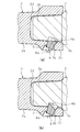
- (A) is an expanded sectional view showing switching a locked state and a non-locking state by rotating the locking member provided in the junctional part of a bucket tooth assembly and an adapter.
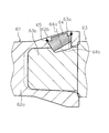
- A) is an expanded sectional view showing the composition around the locking member provided in the joined part of the bucket tooth assembly of the construction machine concerning other embodiments of the present invention.
- (B) is the expanded sectional view which changed the angle which looks at the latching member of (a) by 90 degrees.
- the expanded sectional view which shows the structure of the connection part of the bucket tooth assembly of the construction machine which concerns on other embodiment of this invention.
- the teeth (a bucket tooth assembly of a construction machine) 2 of the bucket 1 according to the present embodiment are provided at the tip of the lower surface (the upper right end in FIG. 1) which is the digging side of the bucket 1 as shown in FIG. It is attached to each of the plurality of adapters 3 and is replaced when worn by work.
- the bucket tooth assembly corresponds to the tooth 2 and is an assembly in which the locking member 4 is attached to the main body 2a described later. It can be attached as it is.
- the tooth 2 is a claw-like member attached to the tip of the digging portion of the bucket 1 for digging with the bucket 1 as shown in FIG. 2 and has a wedge-like outer shape which becomes thinner toward the tip doing. And as shown in FIG. 2, the tooth 2 has a main body (bucket tooth) 2a, a through hole 2b, a side wall 2c, an abutment surface 2d (see FIG. 3A), and a cavity V1. ,have.
- the main body portion 2a has an outer surface constituted by an upper surface 2e and a lower surface 2f which are substantially rectangular and connected at the tip, and substantially triangular side surfaces 2h and 2i between the upper surface 2e and the lower surface 2f, and a substantially rectangular rear end surface 2g. ing.
- the rear end face 2g has an opening and continues to the cavity V1.
- the space V1 is formed by the inner surface 2v inside the main body 2a.
- the cavity V1 is a concave space formed inside the main body 2a from the rear end face 2g of the tooth 2 toward the tip direction.
- This concave space has a wedge-like shape which becomes thinner toward the tip in the same manner as the outline of the tooth 2.
- An insertion portion 3b of an adapter 3 described later is inserted into the hollow portion V1.
- Side wall portion 2c forms both side surfaces of cavity portion V1 formed in main body portion 2a by a protruding portion on the rear end side of side surfaces 2h and 2i, and a through hole 2b described later on one side (side surface 2i) It is formed.
- the through hole 2b is provided in the side wall 2c, and has an opening 2k opened to the outside, and an insertion part 2j smaller in diameter than the opening 2k and into which a locking member 4 described later is inserted.
- the through hole 2b penetrates from the side surface 2i on one side of the main body 2a to the cavity V1, and extends outward from the cavity V1 side along the width direction of the tooth 2 (the BL direction in FIG. 3A).
- the teeth 2 are formed to be inclined in the direction approaching the tip.
- the locking member 4 mentioned later is inserted in this through-hole 2b.
- the insertion part 2j which the inserted locking member 4 fits is a space which has a shape of a part of frusto-conical which is a rotary body.
- the small diameter side of the space is on the side wall 2c side of the tooth 2, and the large diameter side is on the hollow portion V1 side.
- the rotation axis of the frusto-conical (the central axis of the insertion portion 2i of the through hole 2b; hereinafter referred to as the central axis of the through hole 2b) of the frusto-conical from the large diameter side to the small diameter side is the width direction of the tooth 2 (FIG. 3 (a It is disposed to be inclined from the BL direction of)) to the tip of the tooth 2.
- the through hole 2 b has an inner diameter larger than the outer diameter of the locking member 4 described later by the amount of play.
- the shape of the remaining portion outside the above-described frusto-conical insertion portion 2 j is the shape of the other portion of the frusto-conical.
- the contact surface 2d is a part of the inner surface 2v and is a V-shaped inner wall surface forming a cavity V1 inside the main body 2a, and a contact surface 3bb on the adapter 3 side described later Abuts against
- the state in which the contact surface 2 d of the tooth 2 is in contact with the contact surface 3 bb of the adapter 3 is the state in which the tooth 2 is inserted deepest into the adapter 3.
- this state is referred to as a contact state.
- Adapter 3 As shown in FIG. 1, a plurality of adapters 3 are provided at the lower end of the bucket 1, and the teeth 2 described above are attached to each of the adapters 3. And the adapter 3 has the recessed part 3a and the insertion part 3b, as shown in FIG.
- the recess 3 a is a bottomed groove, and is formed on one side surface (side wall 3 ba) of the insertion portion 3 b of the adapter 3.
- the recess 3a has the shape of the other part of the truncated cone, and when the tooth 2 is fitted to the adapter 3 in a contact state, a part of the substantially frusto-conical space of the through hole 2b of the tooth 2 (insertion part 2j) and continuously form one completed substantially frusto-conical shaped space.
- the bottom of the recess 3a is the large diameter side bottom surface of the completed substantially frusto-conical space, and the portion closest to the tooth rear end of the bottom of the recess 3a is generally located on the side wall 3ba of the adapter 3 . Therefore, the recess 3 a is constituted by a surface having a curved surface of a substantially truncated cone on the tip side of the tooth 2 and a flat surface of a substantially truncated cone on the rear end side of the tooth 2. Then, a part (bottom 4b) of the locking member 4 is inserted into or retracted from the recess 3a by rotating the locking member 4 inserted in the through hole 2b.
- the state in which the bottom 4 b of the locking member 4 is inserted into the recess 3 a means the locked state of the tooth 2.
- the state in which the bottom 4b of the locking member 4 retracts from within the recess 3a and the entire locking member 4 is contained within the through hole 2b means the non-locking state of the tooth 2.
- the insertion portion 3 b is formed in accordance with the shape of the cavity V 1 formed in the tooth 2, and is inserted into the cavity V 1 formed in the interior of the tooth 2.
- the abutment surface 3bb is an outer wall surface of the insertion portion 3b that abuts against the abutment surface 2d on the tooth 2 side in a state where the tooth 2 is attached. As described above, the contact surface 3bb receives the load applied to the tooth 2 during work by the surface on the adapter 3 side.
- the locking member 4 is a substantially frusto-conical member attached so that the tooth 2 does not come off the adapter 3 and, as shown in FIG. 2, from the side of the cavity V1 in the through hole 2a on the tooth 2 side Be inserted. Further, as shown in FIG. 3A, the locking member 4 has a locking member main body having a substantially frusto-conical shape, and a rotation shaft (a rotation shaft of the locking member) 4a of the locking member main body. It has a bottom part 4b and a tool insertion part 4c.
- the rotation shaft 4a of the locking member 4 and the central axis of the through hole 2b into which the locking member 4 is inserted are the same, and the locking member 4 is rotatable in the through hole 2b.
- the shape of the main body of the locking member 4 is, as shown in FIG. 4A, a completed frustoconical space formed by the through hole 2b of the tooth 2 and the recess 3a of the adapter 3 in an abutting state.
- the shape of the space on the side of the through hole 2b of the truncated frusto-conical space which is cut at the surface forming the cavity V1 of the tooth 2 and cut.
- the main body of the locking member 4 has a shape similar to the frusto-conical space in the through hole 2b of the tooth 2 by the amount of play, and substantially forms the shape of a part of the frusto-conical as described above Have.
- the most rear end portion of the cutting surface tooth 2 is approximately equal to the most rear end position of the frusto-conical space bottom.
- the rotation axis 4a of the main body of the locking member 4 is the same as the rotation axis of the frusto-conical space formed by the through hole 2b and the recess 3a.
- the rotation shaft 4a is a rotation center when rotating the locking member 4 in the through hole 2b using the tool T (see FIG. 2).
- the bottom 4b has a substantially frusto-conical engagement due to the difference in length of the outer peripheral surface (the generatrix) of the substantially frusto-conical outer shape in the sectional view of the locking member 4.
- the stopper 4 is formed obliquely with respect to the rotation shaft 4 a. Then, as described above, the bottom 4b of the locking member 4 is flush with the inner surface of the tooth forming the cavity V1 of the tooth 2 at a specific rotational position.
- the tool insertion portion 4c is provided on the surface orthogonal to the rotation shaft 4a of the portion extending from the small diameter side of the substantially frusto-conical shape in the locking member 4, and is disposed in the opening 2k of the through hole 2b There is.
- the tool insertion portion 4c is a groove into which the end portion Ta of a tool T (see FIG. 2) for manually rotating the locking member 4 is inserted, and the shape according to the shape of the end portion Ta of the tool T (A square in FIG. 3B) is formed.
- a groove is provided in a part of the outer periphery of the extended portion, and a C-ring 5 described later is wound around the groove.
- 3B is a view around the insertion hole 2b from the viewpoint A of FIG. 3A.
- the locking member 4 is unintentionally rotated due to vibration, impact or the like generated during the operation of the construction machine, except when the locking member 4 is manually rotated using the tool T.
- the C ring (rotation preventing member) 5 is provided to prevent the rotation of the locking member 4.
- the C ring 5 is a member in which an elastic member made of metal, resin, rubber or the like is formed in a U shape, and is in close contact with a groove provided on the outer peripheral surface of the locking member 4. Both ends of the C ring 5 are fixed to the side wall 2c.
- the locking member 4 is in close contact with the C ring 5 and is prevented from rotating from a predetermined position by friction.
- a part (bottom 4b) of the locking member 4 inserted in the through hole 2b of the tooth 2 is the adapter 3. It does not enter into the concave portion 3a on the side, and is accommodated in the through hole 2b (non-locking state). At this time, when the tooth 2 is not in the non-locking state when attached, the locking member 4 may be rotated using the tool T to form the non-locking state.
- the insertion portion 3 b of the adapter 3 can be inserted into the hollow portion V 1 of the tooth 2.
- the locking member 4 is rotated 180 degrees from the non-locking state using a tool T, as shown in FIG. As shown, the state is shifted to a state (locked state) in which a part (bottom 4b) of the locking member 4 has entered into the recess 3a on the adapter 3 side.
- the bottom 4b of the locking member 4 entering the recess 3a on the adapter 3 side moves the locking member integrally with the tooth 2 when a force is applied to the tooth 2 in a direction away from the adapter 3. A part of 4 is caught in the recess 3 a of the adapter 3. Thereby, the locked state in which the tooth 2 does not come off from the adapter 3 can be formed.
- the locking member 4 is configured not to be loaded.
- the adapter 3 and the locking member 4 are in contact with each other in the contact state of the tooth 2 and the adapter 3, but the load applied to the tooth 2 is received by the respective contact surfaces 2d and 3bb, There is no load on the locking member 4.
- the locking member 4 moves in a direction away from the adapter 3 and does not contact the adapter 3 It becomes. For this reason, similarly, no load is applied to the locking member 4 in the direction in which the tooth 2 is pushed into the adapter 3. Therefore, the locking member 4 only needs to have a function to lock the tooth 2 so that the tooth 2 does not come off the adapter 3. Therefore, the locking member 4 is prevented from being damaged by the load applied to the tooth 2 during work. it can.
- the rotation shaft 54a differs from the first embodiment in that a bolt (rotation preventing member) 55 is used to prevent rotation of the locking member 54 having a groove 54c formed on the outer peripheral surface by rotating around the center of the frame.
- the locking member 54 is rotated about the rotation shaft 54a. Then, the bottom 54 b of the locking member 54 can be taken in and out of the recess 53 a of the adapter 53. Then, in a state in which the main body 52a of the tooth 52 is locked to the adapter 53 by the locking member 54, in the bolt hole 52c formed on the side surface of the main body 52a in order to suppress the rotation of the locking member 54. Insert the bolt 55 into the.
- the tip of the bolt 55 gets into the groove 54 c formed in the outer peripheral surface of the locking member 54.
- the groove part 54c is provided in two places which oppose in the outer peripheral surface of the latching member 54. As shown in FIG.
- the distal end of the bolt 55 is inserted into the groove 54c, so that the locking member 54 can be prevented from rotating about the rotation shaft 54a.
- the recessed part 53a is provided in the left-right-both-sides surface of the adapter 53. As shown in FIG.
- the tooth 52 can be locked to the adapter 53 by the locking member 54. Therefore, the teeth 52 having different shapes can be attached, and parts can be shared.
- the substantially frusto-conical locking member 4 having the large-diameter portion on the adapter 3 side (insertion side) is rotated about the rotation shaft 4 a to obtain the locked state and the non-engaged state.
- the example has been described by switching to the stop state.
- the present invention is not limited to this.
- a locking member 64 may be used which is attached with the large diameter portion facing outward instead of the adapter 63 side.
- the substantially frusto-conical locking member 64 is passed through the rotation shaft 64a.
- the bottom portion 64b on the small diameter side can be taken in and out of the recess 63a on the adapter 63 side only by rotating in the hole 62b.
- a C ring (rotation preventing member) 65 is provided so that the locking member 64 does not rotate due to vibration or impact.
- the locked state of the tooth 62 with respect to the adapter 63 can be easily switched between the locked state and the non-locked state simply by rotating the locking member 64. Further, since the locking member 64 can be rotated from the large diameter side, a larger torque can be obtained with a smaller force.
- through holes for inserting the locking members may be provided on the left and right sides of the bucket tooth.
- the teeth can be locked to the adapter on both sides of the bucket tooth by forming recesses on the left and right sides on the adapter side as well.
- the recess on the adapter side may be a simple through hole penetrating the insertion portion, or may be a recess formed along the width direction of the insertion portion. In this case, although a part of the locking member and the recess are in line contact, it is possible to lock the tooth so as not to be separated from the adapter.
- the locked state can be formed between the surfaces, and the locking member can be formed. It is more preferable that the recessed part is formed according to the shape of a locking member like the said Embodiment 1, 2 in the point that generation
- the bucket tooth assembly of the construction machine according to the present invention has an effect that the bucket tooth can be fixed to the adapter with a simple configuration without shortening the life of the parts, and therefore, the mounting structure of various digging tools Is widely applicable.
Landscapes
- Engineering & Computer Science (AREA)
- Mining & Mineral Resources (AREA)
- Civil Engineering (AREA)
- General Engineering & Computer Science (AREA)
- Structural Engineering (AREA)
- Component Parts Of Construction Machinery (AREA)
Abstract
Description
具体的には、上記公報に開示されたツース組立体の取付け構造では、アダプタ側の側端部に設けられた突起部(バー)を、ツース組立体側に設けられた溝部内に挿入し、C字状のロック部材を回転させることで、アダプタに対してツース組立体を固定する。
すなわち、上記公報に開示されたツース組立体の取付構造では、アダプタ側に設けた突起部(バー)を用いてツース組立体を固定している。このため、作業時等においてツースに大きな負荷がかかった際に、突起部が変形・破損しやすく、アダプタを含む部品寿命が短くなってしまうおそれがある。その場合、突起部、すなわちアダプタは、ツース組立体と異なり交換できないため、面倒な補修が必要となる。
これにより、作業時にバケットツースに掛かる大きな負荷を当接面において受けることで、係止部材に大きな負荷が掛かることはない。また、アダプタ側には係止部材の底部が係止される凹部が形成されているだけであるため、アダプタ側が破損等することはない。さらに、係止部材は回転軸を中心に回転させることで、容易に、バケットツース組立体の係止状態と非係止状態とを切り換えることができる。
この結果、簡易な構成によって、アダプタを含む部品寿命の短縮化を回避しつつ、アダプタに対して容易に着脱することが可能なバケットツース組立体を得ることができる。
これにより、回転軸を中心として係止部材を回転させるだけで、係止部材の底部を貫通孔から突出させたり、引っ込めたりすることができる。この結果、係止部材を回転させるだけの操作で、容易にバケットツース組立体の係止状態と非係止状態とを切り換えることができる。
これにより、ツースがアダプタに装着された状態では、ツースから係止部材が脱落してしまうことを防止できる。そして、簡易な構造により、回転させるだけで、係止状態と非係止状態とを容易に切り換えることが可能となる。
これにより、係止部材を回転させて第1状態とするだけで、バケットツース組立体をアダプタに対して容易に着脱することができる。
これにより、回転軸を中心として係止部材を回転させるだけで、係止部材の底部を貫通孔から突出させたり、引っ込めたりすることができる。この結果、係止部材を回転させるだけの操作で、容易にバケットツース組立体の係止状態と非係止状態とを切り換えることができる。
これにより、貫通孔の外側から工具を挿入して、係止部材を容易に回転させることができる。
これにより、例えば、バケットを用いた作業中に生じる振動等によって係止部材が回転してしまうことを防止することができる。この結果、係止部材の意図しない回転によって、アダプタからバケットツース組立体が脱落してしまうことを確実に回避することができる。
本発明の一実施形態に係るツース(建設機械のバケットツース組立体)2およびその取付構造について、図1~図4(b)を用いて説明すれば以下の通りである。
ツース2は、図2に示すように、バケット1によって掘削を行うためにバケット1の掘削部分の先端に取り付けられた爪状の部材であって、先端に向かって薄くなるクサビ状の外形を有している。そして、ツース2は、図2に示すように、本体部(バケットツース)2aと、貫通孔2bと、側壁部2cと、当接面2d(図3(a)参照)と、空洞部V1と、を有している。
アダプタ3は、図1に示すように、バケット1の下面端部に複数設けられており、それぞれに対して、上述したツース2が取り付けられる。そして、アダプタ3は、図2に示すように、凹部3aと、挿入部3bと、を有している。
係止部材4は、ツース2がアダプタ3から脱落しないように取り付けられる略截頭円錐状の部材であって、図2に示すように、ツース2側の貫通孔2a内に空洞部V1側から挿入される。また、係止部材4は、図3(a)に示すように、略截頭円錐形状を持つ係止部材本体と、その係止部材本体の回転軸(係止部材の回転軸)4aと、底部4bと、工具挿入部4cと、を有している。
係止部材4の本体の形状は、図4(a)に示すように、当接状態でツース2の貫通孔2bとアダプタ3の凹部3aとにより形成される完成した截頭円錐状の空間を、ツース2の空洞部V1を形成する面で切断し、その切断された截頭円錐状空間の貫通孔2b側の空間の形状である。換言すると、係止部材4の本体は、ツース2の貫通孔2bにある截頭円錐の空間と遊び分だけ小さい相似の形状を有し、実質的に上述の截頭円錐の一部の形状を有する。切断面のツース2の最も後端にある部位は、截頭円錐状空間底部の最も後端の位置に略等しい。係止部材4の本体の回転軸4aは、貫通孔2bと凹部3aとによって形成される截頭円錐空間の回転軸と同一である。
底部4bは、図3(a)に示すように、係止部材4の断面視において略截頭円錐状の外形の外周面(母線)の長さが異なることで、略截頭円錐状の係止部材4における回転軸4aに対して斜めに形成されている。そして、上述のように、ある特定の回転位置において係止部材4の底部4bはツース2の空洞部V1を形成するツース内面と同一面となる。そして、この特定の回転位置から係止部材4を180度回転させると、係止部材4のツース2の最後端にあった部位が、ツース2の空洞部面からアダプタ凹部3aの底部のツース2の先端側の位置に移動し、係止部材4とアダプタ3とが係合する。これにより、回転軸4aを中心に係止部材4を回転させるだけで、係止部材4の一部(底部4b)が、アダプタ3側の凹部3a内に挿入した状態(係止状態)と、凹部3a内から退避した状態(非係止状態)とを切り換えることができる。
回避することができる。
本実施形態では、以上のような構成を備えており、アダプタ3に対するツース2の係止状態(第2状態)と非係止状態(第1状態)とを切り換えている。
次に、アダプタ3の挿入部3bがツース2の空洞部V1内へ挿入された状態において、工具Tを用いて係止部材4を非係止状態から180度回転させ、図4(b)に示すように、係止部材4の一部(底部4b)がアダプタ3側の凹部3a内に進入した状態(係止状態)へ移行させる。
本発明の他の実施形態に係る建設機械のツースについて、図5(a)および図5(b)を用いて説明すれば以下の通りである。
なお、図5(b)に示すように、アダプタ53の左右両側面に凹部53aが設けられていることが好ましい。
以上、本発明の一実施形態について説明したが、本発明は上記実施形態に限定されるものではなく、発明の要旨を逸脱しない範囲で種々の変更が可能である。
上記実施形態1,2では、アダプタ3側(挿入側)に径大部を有する略截頭円錐状の係止部材4を、回転軸4aを中心に回転させることで、係止状態と非係止状態とを切り換える例を挙げて説明した。しかし、本発明はこれに限定されるものではない。
この場合でも、上記実施形態と同様に、ツース62の本体部62aの内部へアダプタ63の挿入部63bを挿入した状態で、回転軸64aを中心に略截頭円錐状の係止部材64を貫通孔62b内において回転させるだけで、径小部側の底部64bを、アダプタ63側の凹部63a内に出し入れすることができる。そして、この係止部材64が振動や衝撃等で回転しないように、Cリング(回り止め部材)65を設けている。
上記実施形態1,2では、ツース2の本体部2aの一方の側面にだけ、係止部材4を挿入する貫通孔2bが設けられている例を挙げて説明した。しかし、本発明はこれに限定されるものではない。
上記実施形態では、アダプタ3側の凹部3aが、係止部材4の一部の形状に合わせて形成されている例を挙げて説明した。しかし、本発明はこれに限定されるものではない。
この場合には、係止部材の一部と凹部とは線で接触することになるものの、ツースをアダプタから離間しないように係止することは可能である。
2 ツース(建設機械のバケットツース組立体)
2a 本体部(バケットツース)
2b 貫通孔
2c 側壁部
2d 当接面
2e 上面
2f 下面
2g 後端面
2h,2i 側面
2j 挿入部
2k 開口部
2v 内面
3 アダプタ
3a 凹部
3b 挿入部
3ba 側壁部
3bb 当接面
4 係止部材
4a 回転軸(係止部材の回転軸、貫通孔の中心軸)
4b 底部
4c 工具挿入部
5 Cリング(回り止め部材)
52 ツース(建設機械のバケットツース)
52a 本体部(バケットツース)
52b 貫通孔
52c ボルト孔
53 アダプタ
53a 凹部
53b 挿入部
54 係止部材
54a 回転軸
54b 底部
54c 溝部
55 ボルト(回り止め部材)
62 ツース(建設機械のバケットツース)
62a 本体部(バケットツース)
62b 貫通孔
63 アダプタ
63a 凹部
63b 挿入部
64 係止部材
64a 回転軸
64b 底部
65 Cリング(回り止め部材)
T 工具
Ta 先端部
V1 空洞部
Claims (8)
- 建設機械のバケットの先端部に設けられたアダプタに対して交換可能な状態で装着されるバケットツース組立体であって、
前記アダプタを挿入するための空洞部と、前記空洞部内にあって作業中に掛かる負荷を受け止めるように前記アダプタの外面に対して当接する当接面と、前記ツースの外面において三角形の形状を有する側面と、前記側面に設けられ前記アダプタに対して装着された状態において前記アダプタまで相通し中心軸を有する貫通孔と、を有するバケットツースと、
前記貫通孔内に嵌合され、前記中心軸方向に沿って配置された回転軸と前記軸方向における前記アダプタ側の端部に設けられた底部とを有しており、前記回転軸を中心に回転させることで前記底部が前記貫通孔内に収まる第1状態と前記底部が前記アダプタ側の凹部に向けて突出する第2状態とを切り換える係止部材と、
を備えている建設機械のバケットツース組立体。 - 前記係止部材は、前記回転軸に沿った断面視において、側面部分の長さが左右で非対称となっている、
請求項1に記載の建設機械のバケットツース組立体。 - 前記係止部材は、前記回転軸によって形成される截頭円錐の一部の形状を有し、
前記截頭円錐の一部の形状は、前記截頭円錐の底面の周上から、前記回転軸に対して斜めに切断された切断面が前記係止部材の前記底部に相当する、
請求項1または2に記載の建設機械のバケットツース組立体。 - 前記バケットツースは、前記空洞部を形成する内面を有し、
前記係止部材の前記底部は、前記第1状態において前記内面と面一である、
請求項3に記載の建設機械のバケットツース組立体。 - 前記係止部材の前記回転軸は、前記バケットツースの幅方向に沿って、前記空洞部から外方に向かって前記バケットツースの先端に近づく方向に傾いて配置される、
請求項1または2に記載の建設機械のバケットツース組立体。 - 前記係止部材は、前記貫通孔に挿入された状態において外部に露出する位置に、前記回転軸を中心に回転させられる際に用いられる工具の一部が挿入される工具挿入部を、有している、
請求項1または2に記載の建設機械のバケットツース組立体。 - 前記係止部材の回転を抑止する回り止め部材をさらに備えている、
請求項1または2に記載の建設機械のバケットツース組立体。 - 先端部にバケットツース組立体が装着された建設機械のバケットであって、
前記先端部に設けられたアダプタと、
側面に形成されており前記アダプタまで挿通する貫通孔と、前記貫通孔に挿入され底部が前記貫通孔内に収まる第1状態と前記底部が前記貫通孔から突出する第2状態とを回転によって切り換え可能な係止部材と、を有し、前記アダプタに装着されるバケットツース組立体と、
前記アダプタにおける前記バケットツース組立体の前記貫通孔に相対する部位に設けられ、前記貫通孔とともに截頭円錐状の空間を形成し、前記バケットツース組立体の先端側に前記截頭円錐の曲面、前記バケットツース組立体の後端側に前記截頭円錐の大径側の底面、に相当する面をそれぞれ有するとともに、前記第2状態において前記係止部材が嵌入することで前記バケットツース組立体が前記バケットに係止される凹部と、
を備える建設機械のバケット。
Priority Applications (4)
| Application Number | Priority Date | Filing Date | Title |
|---|---|---|---|
| US13/818,770 US8997383B2 (en) | 2011-05-09 | 2012-04-26 | Construction-equipment bucket-tooth assembly and bucket provided to same |
| DE112012000171.0T DE112012000171B4 (de) | 2011-05-09 | 2012-04-26 | Löffelzahnordnung einer Bauausrüstung und an der Bauausrüstung vorgesehener Löffel |
| KR1020137004114A KR101477177B1 (ko) | 2011-05-09 | 2012-04-26 | 건설 기계의 버킷 투스 조립체, 및 이것을 구비한 버킷 |
| CN201280003442.0A CN103180524B (zh) | 2011-05-09 | 2012-04-26 | 建设机械的斗齿组装体及具备该组装体的铲斗 |
Applications Claiming Priority (2)
| Application Number | Priority Date | Filing Date | Title |
|---|---|---|---|
| JP2011104555A JP5504205B2 (ja) | 2011-05-09 | 2011-05-09 | 建設機械のバケットツース組立体、およびこれを備えたバケット |
| JP2011-104555 | 2011-05-09 |
Publications (1)
| Publication Number | Publication Date |
|---|---|
| WO2012153651A1 true WO2012153651A1 (ja) | 2012-11-15 |
Family
ID=47139135
Family Applications (1)
| Application Number | Title | Priority Date | Filing Date |
|---|---|---|---|
| PCT/JP2012/061260 Ceased WO2012153651A1 (ja) | 2011-05-09 | 2012-04-26 | 建設機械のバケットツース組立体、およびこれを備えたバケット |
Country Status (6)
| Country | Link |
|---|---|
| US (1) | US8997383B2 (ja) |
| JP (1) | JP5504205B2 (ja) |
| KR (1) | KR101477177B1 (ja) |
| CN (1) | CN103180524B (ja) |
| DE (1) | DE112012000171B4 (ja) |
| WO (1) | WO2012153651A1 (ja) |
Families Citing this family (9)
| Publication number | Priority date | Publication date | Assignee | Title |
|---|---|---|---|---|
| CN103958792B (zh) * | 2011-11-23 | 2017-12-26 | 埃斯科公司 | 磨损组件 |
| US9840825B2 (en) | 2013-08-28 | 2017-12-12 | Caterpillar Inc. | Implement end cutting-bit |
| US10106960B2 (en) | 2015-11-25 | 2018-10-23 | Caterpillar Inc. | Lock assembly for ground engaging tool |
| US20170328035A1 (en) * | 2016-05-12 | 2017-11-16 | Hensley Industries, Inc. | Connector systems in earth engaging wear member assemblies |
| US10508418B2 (en) | 2016-05-13 | 2019-12-17 | Hensley Industries, Inc. | Stabilizing features in a wear member assembly |
| USD918965S1 (en) | 2018-06-19 | 2021-05-11 | Hensley Industries, Inc. | Ground engaging wear member |
| US11371221B2 (en) * | 2019-04-24 | 2022-06-28 | Caterpillar Inc. | Ground engaging tool assembly with ground engaging tip |
| JP7160777B2 (ja) * | 2019-09-13 | 2022-10-25 | 株式会社小松製作所 | バケット用のツース取付構造、及びバケット用のツース |
| JP7164582B2 (ja) * | 2020-11-20 | 2022-11-01 | 株式会社樋口製作所 | バケット用ツース着脱構造及びそのバケット |
Citations (3)
| Publication number | Priority date | Publication date | Assignee | Title |
|---|---|---|---|---|
| JP2009013788A (ja) * | 2002-09-19 | 2009-01-22 | Esco Corp | 連結装置 |
| JP2010526953A (ja) * | 2007-05-10 | 2010-08-05 | エスコ・コーポレイション | 掘削装置のための磨耗アッセンブリ |
| JP2011511180A (ja) * | 2008-01-08 | 2011-04-07 | エスコ・コーポレイション | 土工ロール用先端部 |
Family Cites Families (7)
| Publication number | Priority date | Publication date | Assignee | Title |
|---|---|---|---|---|
| US5337495A (en) * | 1993-04-30 | 1994-08-16 | Pippins Sherlock K | Tooth assembly for excavating apparatus |
| US5718070A (en) * | 1995-11-13 | 1998-02-17 | Gh Hensley Industries, Inc. | Self-adjusting tooth/adapter connection system for material displacement apparatus |
| US5913605A (en) * | 1997-09-17 | 1999-06-22 | G. H. Hensley Industries, Inc. | Rotary lock system for wear runner assembly |
| JP2000104293A (ja) | 1998-09-30 | 2000-04-11 | Yutani Heavy Ind Ltd | 掘削用バケットのツース接合部構造 |
| US7762015B2 (en) | 2006-08-16 | 2010-07-27 | Caterpillar Inc | Ground engaging tool system |
| US8061064B2 (en) | 2007-05-10 | 2011-11-22 | Esco Corporation | Wear assembly for excavating equipment |
| JP5210415B2 (ja) * | 2011-05-09 | 2013-06-12 | 株式会社小松製作所 | 建設機械のバケットツース |
-
2011
- 2011-05-09 JP JP2011104555A patent/JP5504205B2/ja not_active Expired - Fee Related
-
2012
- 2012-04-26 KR KR1020137004114A patent/KR101477177B1/ko not_active Expired - Fee Related
- 2012-04-26 US US13/818,770 patent/US8997383B2/en not_active Expired - Fee Related
- 2012-04-26 CN CN201280003442.0A patent/CN103180524B/zh not_active Expired - Fee Related
- 2012-04-26 DE DE112012000171.0T patent/DE112012000171B4/de not_active Expired - Fee Related
- 2012-04-26 WO PCT/JP2012/061260 patent/WO2012153651A1/ja not_active Ceased
Patent Citations (3)
| Publication number | Priority date | Publication date | Assignee | Title |
|---|---|---|---|---|
| JP2009013788A (ja) * | 2002-09-19 | 2009-01-22 | Esco Corp | 連結装置 |
| JP2010526953A (ja) * | 2007-05-10 | 2010-08-05 | エスコ・コーポレイション | 掘削装置のための磨耗アッセンブリ |
| JP2011511180A (ja) * | 2008-01-08 | 2011-04-07 | エスコ・コーポレイション | 土工ロール用先端部 |
Also Published As
| Publication number | Publication date |
|---|---|
| US8997383B2 (en) | 2015-04-07 |
| CN103180524A (zh) | 2013-06-26 |
| KR101477177B1 (ko) | 2014-12-29 |
| DE112012000171T5 (de) | 2013-08-01 |
| US20130152433A1 (en) | 2013-06-20 |
| DE112012000171B4 (de) | 2015-01-22 |
| JP5504205B2 (ja) | 2014-05-28 |
| JP2012233378A (ja) | 2012-11-29 |
| CN103180524B (zh) | 2015-07-08 |
| KR20130069733A (ko) | 2013-06-26 |
Similar Documents
| Publication | Publication Date | Title |
|---|---|---|
| JP5504205B2 (ja) | 建設機械のバケットツース組立体、およびこれを備えたバケット | |
| JP5210415B2 (ja) | 建設機械のバケットツース | |
| KR102199939B1 (ko) | 지반 결합 도구용 리테이너 시스템 | |
| ES2930197T3 (es) | Conjunto de desgaste para excavadora | |
| AU2015241806B2 (en) | Drilling tool | |
| JP5055464B2 (ja) | 作業機および取付けピン組立て体 | |
| JP2019510145A (ja) | 土工用装備用摩耗アセンブリ | |
| KR20170015511A (ko) | 안내 및 체결 오목부를 구비한 결합 핀을 갖는 절삭 헤드를 포함하는 회전 절삭 공구 | |
| EP3227498B1 (en) | Ground engaging tool | |
| AU2016247934B2 (en) | Cap for removably attaching to a head of a fastener and tool retention system comprising a clamp and a wedge assembly including such a cap | |
| JP5954694B1 (ja) | 取付ピン組立体 | |
| JP5096861B2 (ja) | 作業機械の二部材連結構造 | |
| CN218060521U (zh) | 锁销组件和挖掘齿锁销固定系统 | |
| CN217267764U (zh) | 插拔方便的锁销组件及挖掘齿连接系统 | |
| JP2011246974A (ja) | 作業機および取付けピン組立て体 | |
| JP2008179991A (ja) | 足場用壁つなぎ取付ボルト | |
| JP4103595B2 (ja) | 掘削工具 | |
| JP2015036467A (ja) | 掘削工具及び揺動制御管 | |
| JP4751798B2 (ja) | オーガヘッド | |
| JP2018123477A (ja) | 掘削工具 | |
| JP3170770U (ja) | 攪拌兼掘削刃体 | |
| EA051363B1 (ru) | Взаимодействующий с грунтом изнашиваемый элемент для оборудования для земляных работ и взаимодействующий с грунтом изнашиваемый узел для оборудования для земляных работ | |
| HK1226459A1 (en) | Drilling tool |
Legal Events
| Date | Code | Title | Description |
|---|---|---|---|
| 121 | Ep: the epo has been informed by wipo that ep was designated in this application |
Ref document number: 12782379 Country of ref document: EP Kind code of ref document: A1 |
|
| ENP | Entry into the national phase |
Ref document number: 20137004114 Country of ref document: KR Kind code of ref document: A |
|
| WWE | Wipo information: entry into national phase |
Ref document number: 13818770 Country of ref document: US |
|
| WWE | Wipo information: entry into national phase |
Ref document number: 1120120001710 Country of ref document: DE Ref document number: 112012000171 Country of ref document: DE |
|
| 122 | Ep: pct application non-entry in european phase |
Ref document number: 12782379 Country of ref document: EP Kind code of ref document: A1 |